

Fisher NotchFlo DST CL300, NotchFlo DST CL600, NotchFlo DST CL1500, NotchFlo DST CL2500, NotchFlo DST CL900 Instruction Manual
Instruction Manual
D103211X012
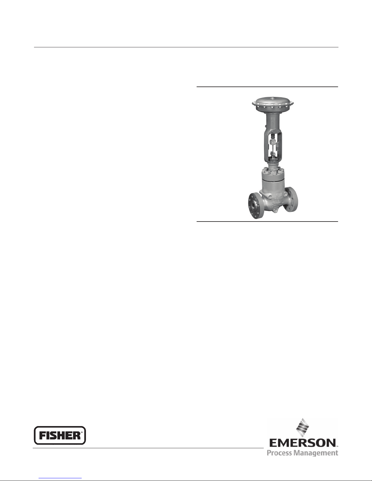
Fisherr NotchFlo™ DST Control Valve
NotchFlo DST Valve
March 2011
Contents
Introduction 1.................................
Scope of Manual 1.............................
Description 1.................................
Specifications 3...............................
Installation 4...................................
Maintenance 5.................................
Packing Maintenance 7.........................
Adding Packing Rings 9.....................
Replacing Packing 9........................
Trim Removal 12..............................
Valve Plug Maintenance 12......................
Lapping Seats 13..............................
Trim Replacement 14..........................
Parts Ordering 15...............................
Parts Kits 16...................................
Parts List 16...................................
Introduction
Figure 1. Fisher NotchFlo DST Control Valve
W9050
Scope of Manual
This instruction manual includes installation, maintenance, and parts information for the Fisher NotchFlo DST control
valve. Refer to separate manuals for instructions covering the actuator, positioner, and accessories.
Do not install, operate, or maintain NotchFlo DST valves without being fully trained and qualified in valve, actuator,
and accessory installation, operation, and maintenance. To avoid personal injury or property damage, it is important
to carefully read, understand, and follow all the contents of this manual, including all safety cautions and warnings. If
you have any questions about these instructions, contact your Emerson Process Management sales office before
proceeding.
Description
The NotchFlo DST globe (figure 1) and angle valves have metal seats, cage guiding, quick change trim, and
push‐down‐to‐close valve plug action. All available valve sizes and pressure ratings use balanced valve plugs with the
exception of CL900 and CL1500 (NPS 1 and 1‐1/2 valves) which use an unbalanced valve plug. To provide a seal
between the cage and a balanced valve plug, the balanced valve plugs use a pressure‐assisted spring‐loaded seal ring.
A properly sized NotchFlo DST valve with 3‐, 4‐, or 6‐stage dirty service anti‐cavitation trim (figure 2) offers excellent
control of high pressure drop liquids with entrained solids, while avoiding the damaging effects of cavitation and
erosive solids.
www.Fisher.com

NotchFlo DST Valve
March 2011
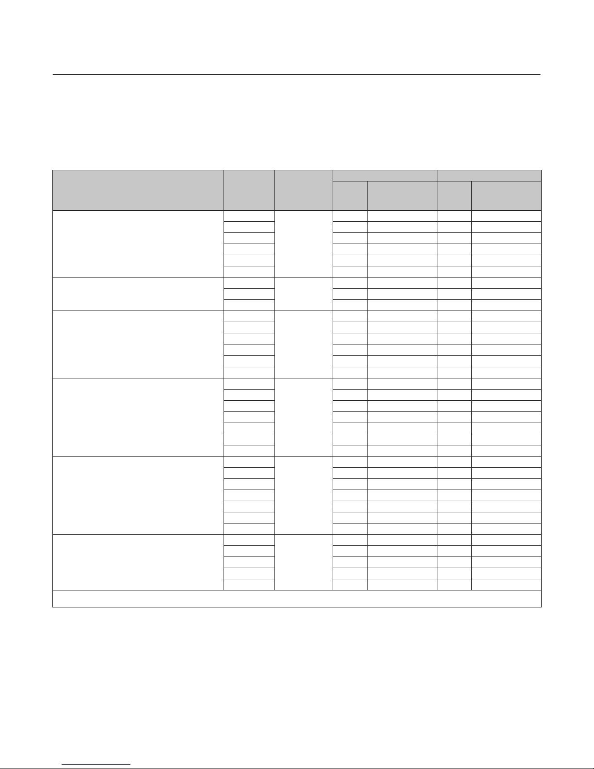
Table 1. Specifications
Instruction Manual
D103211X012
Available Valves
CL600 3‐Stage: Level C only
CL900 and CL1500 v NPS 4, 4‐Stage: Levels A, B, and
(1)
C
CL1500 w NPS 6, 4‐Stage: Level C only
CL2500 6‐Stage: Level C only
End Connection Styles and Ratings
(2)
Also see table 2
Shutoff Classification
Class V: [5x10
(0.0005 mL/min/psid/in) of water at service pressure
drop] per ANSI/FCI 70‐2 and IEC 60534‐4
Flow Characteristic
Linear
Flanged: Consistent with CL600, 900, 1500, and 2500
per ASME B16.34
Socket Welding: Consistent with CL600, 900, and
Flow Direction
Flow up
1500 per ASME B16.34
Buttwelding: Consistent with CL600, 900, 1500, and
2500 per ASME B16.34
1. Levels A, B, and C provide for varied pressure drops and capacity.
2. The pressure/temperature limits in this manual and any applicable standard or code limitation for valve should not be exceeded.
Approximate Weights
See table 2
Figure 2. Fisher NotchFlo DST Trim
12m3
/sec/bar/mm of port diameter
W8538-1
NotchFlo DST control valves utilize a high resistance, multi‐stage, axial flow path (or passage) where fluid flow is
parallel to the axis of the plug and cage.
Pressure reduction occurs throughout the length of the plug; thus individual stages aren't exposed to the full pressure
differential. Therefore, trim life is enhanced.
NotchFlo DST trim utilizes a series of notched flow restrictions and expansions to control the pressure drop of the
fluid. The amount of pressure drop per stage is controlled to prevent cavitation problems and minimize erosion issues.
Flow passage configuration provided by the multi‐stage plug and cage design make the NotchFlo DST valves
well‐suited for applications involving fluids with entrained particles. This is a potentially serious problem for other
anti‐cavitation valve designs which are subject to clogged flow passages.
Design of the trim allows for high rangeability.
2
Instruction Manual
D103211X012
Specifications
Specifications for NotchFlo DST valves are shown in table 1.
Table 2. Approximate Weights (Valve and Bonnet Assemblies)
VALVE DESIGN
3-Stage Globe Valves
4-Stage Globe Valves
3-Stage Angle Valves
4-Stage Angle Valves
4-Stage Cast Angle Valves
6-Stage Angle Valves
1. SWE available on NPS 1, 1-1/2, and 2 only.
2. Screwed end available on NPS 1 and 2 CL600 only.
VALVE SIZE,
NPS
1
2 40 30 90 70
3 70 50 155 110
4 120 80 265 175
6 275 230 610 510
8 510 445 1130 980
2
3 185 140 405 310
4 340 280 750 620
1
2 42 - - - 93 - - 3 86 - - - 190 - - 4 140 - - - 315 - - 6 300 - - - 660 - - 8 605 - - - 1340 - - 1
1-1/2 55 45 120 95
2 95 95 210 210
3 185 - - - 405 - - 4 285 - - - 625 - - 6 560 - - - 1230 - - -
8 1260 - - - 2770 - - -
1
1-1/2 43 35 95 77
2 75 57 165 126
3 148 118 326 260
4 243 200 536 441
6 523 443 1153 977
8 1062 920 2342 2029
1
2 180 170 405 375
3 500 473 1110 1043
4 465 433 1025 955
6 1060 1030 2330 2271
PRESSURE
RATING
CL600
CL900 and
CL1500
CL600
CL900 and
CL1500
CL900 and
CL1500
CL2500
NotchFlo DST Valve
KILOGRAMS POUNDS
Socket Weld
Flanged
20 15 45 35
95 85 210 185
20 - - - 44 - - -
50 40 110 90
40 32 88 71
64 67 140 148
Butt Weld,
Screwed
(1)
,
Flanged
(2)
Socket Weld
March 2011
Butt Weld,
(2)
Screwed
(1)
,
3

NotchFlo DST Valve
March 2011
Instruction Manual
D103211X012
Installation
WARNING
Always wear protective gloves, clothing, and eyewear when performing any installation operations to avoid personal
injury.
Personal injury or property damage caused by sudden release of pressure may result if the valve assembly is installed where
service conditions could exceed the limits given in table 1 or on the appropriate nameplates. To avoid such injury or
damage, provide a relief valve for over‐pressure protection as required by government or accepted industry codes and good
engineering practices.
Check with your process or safety engineer for any additional measures that must be taken to protect against process
media.
If installing into an existing application, also refer to the WARNING at the beginning of the Maintenance section in this
instruction manual.
WARNING
Some bonnet flanges have a tapped hole that was used to handle the bonnet during manufacture. Since this tapped hole
was not designed or intended to support the weight of the valve/bonnet assembly, do not use this tapped hole to lift the
valve assembly or personal injury may result from the assembly falling.
CAUTION
When ordered, the valve configuration and construction materials were selected to meet particular pressure, temperature,
pressure drop, and controlled fluid conditions. Since some body/trim material combinations are limited in their pressure
drop and temperature ranges, do not apply any other conditions to the valve without first checking with your Emerson
Process Management sales office.
1. Before installing the valve, inspect it to ensure that the valve body cavity is free of foreign material.
2. Clean out all pipelines to remove scale, welding slag, and other foreign materials before installing the valve.
3. Flow through the valve must be in the direction indicated by the flow arrow, which is cast on or attached to the
valve body.
4. Use accepted piping practices when installing the valve in the pipeline. For flanged valve bodies, use a suitable
gasket between the body and pipeline flanges.
5. Install a three‐valve bypass around the valve if continuous operation is required during maintenance.
6. If the actuator and valve body are shipped separately, refer to the actuator mounting procedure in the appropriate
actuator instruction manual.
4

Instruction Manual
D103211X012
NotchFlo DST Valve
March 2011
7. If the valve body was shipped without packing installed in the packing box, install the packing before putting the
valve body into service. Refer to instructions given in the Packing Maintenance procedure.
WARNING
Personal injury could result from packing leakage. Valve packing was tightened prior to shipment; however, the packing
might require some readjustment to meet specific service conditions. Check with your process or safety engineer for any
additional measures that must be taken to protect against process media.
Maintenance
Refer to figure 7 through 12.
Valve parts are subject to normal wear and must be inspected and replaced as necessary. Inspection and maintenance
frequency depends on the severity of service conditions. This section includes instructions for packing maintenance
and trim maintenance. All maintenance operations may be performed with the valve in the line.
WARNING
Avoid personal injury or damage to property from sudden release of pressure or uncontrolled process fluid. Before starting
disassembly:
D Do not remove the actuator from the valve while the valve is still pressurized.
D Always wear protective gloves, clothing, and eyewear when performing any maintenance operations to avoid personal
injury.
D Disconnect any operating lines providing air pressure, electric power, or a control signal to the actuator. Be sure the
actuator cannot suddenly open or close the valve.
D Use bypass valves or completely shut off the process to isolate the valve from process pressure. Relieve process pressure
on both sides of the valve. Drain the process media from both sides of the valve.
D Vent the power actuator loading pressure and relieve any actuator spring precompression.
D Use lock‐out procedures to be sure that the above measures stay in effect while you work on the equipment.
D The valve packing box may contain process fluids that are pressurized, even when the valve has been removed from the
pipeline. Process fluids may spray out under pressure when removing the packing hardware or packing rings, or when
loosening the packing box pipe plug.
D Check with your process or safety engineer for any additional measures that must be taken to protect against process
media.
5
NotchFlo DST Valve
March 2011
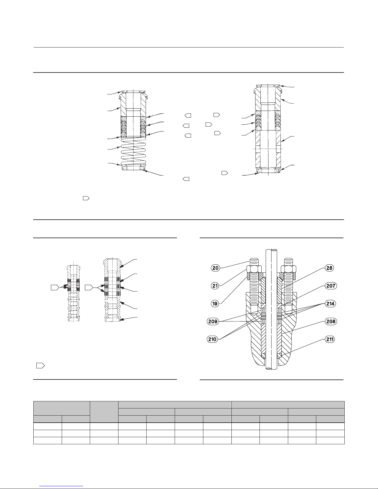
Figure 3. PTFE V‐Ring Packing Arrangements for Plain and Extension Bonnets
UPPER WIPER
(KEY 27)
PACKING
12A7837‐A
B1429‐5
FOLLOWER
(KEY 28)
WASHER
(KEY 25)
SPRING
(KEY 24)
PACKING BOX
RING (KEY 26)
FOR 316 SST
METAL PACKING BOX PARTS
NOTE:
1
AND LOWER WIPER ARE PART OF PACKING SET (KEY 22).
2 REQ'D FOR DOUBLE ARRANGEMENTS, EXCEPT LOWER WIPER.
MALE ADAPTOR, PACKING RING, FEMALE ADAPTOR,
FEMALE
ADAPTOR
PACKING
RING
MALE
ADAPTOR
LOWER
WIPER
1
1
1
1
SINGLE ARRANGEMENTS
FEMALE
1
ADAPTOR
1
PACKING RING
MALE
1
ADAPTOR
1
LOWER
WIPER
Instruction Manual
D103211X012
UPPER WIPER
(KEY 27)
PACKING
FOLLOWER (KEY 28)
SPACER (KEY 24)
PACKING BOX
RING (KEY 26)
FOR ALL OTHER METAL PACKING
BOX PART MATERIALS
Figure 4. Detail of Graphite Ribbon/Filament Packing
for Plain and Extension Bonnets
1
13A9775‐B
12.7 mm
(1/2 INCH)
STEM
1
13A9776‐B
19.1 & 25.4 mm
(3/4 & 1 INCH)
STEM
PACKING
FOLLOWER
(KEY 28)
GRAPHITE
RIBBON
PACKING RING
(KEY 23)
GRAPHITE
FILAMENT
PACKING RING
(KEY 23)
LANTERN
RING (KEY 24)
PACKING BOX
RING (KEY 26)
Figure 5. Detail of Graphite ULF Packing for Plain
Bonnets
SINGLE ARRANGEMENTS
NOTE:
1
0.102 mm (0.004 INCH) THICK SACRIFICIAL ZINC WASHERS;
USE ONLY ONE BELOW EACH GRAPHITE RIBBON RING.
39B9286‐A
SINGLE ARRANGEMENTS
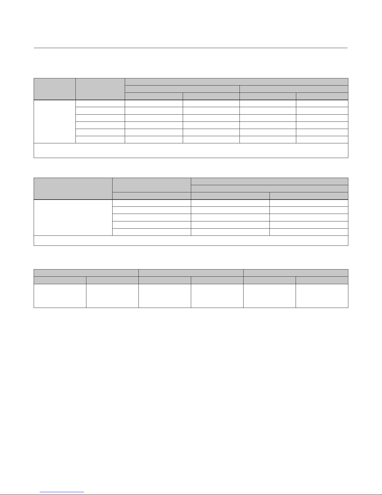
Table 3. CL600 Recommended Torque for Packing Flange Nuts (non live‐loaded)
VALVE STEM DIAMETER
mm Inches NSm LbfSin NSm LbfSin NSm LbfSin NSm LbfSin
PRESSURE
RATING
Minimum Torque Maximum Torque Minimum Torque Maximum Torque
12.7 1/2 CL600 9 81 14 122 4 39 7 58
19.1 3/4 CL600 21 182 31 274 10 87 15 131
25.4 1 CL600 35 310 53 466 17 149 25 223
GRAPHITE TYPE PACKING PTFE TYPE PACKING
6

Instruction Manual
D103211X012
NotchFlo DST Valve
March 2011
Table 4. CL900, 1500, and 2500 Recommended Torque for Packing Flange Nuts (non live‐loaded)
VALVE STEM
DIAMETER
mm Inches Min Max Min Max
12.7 1/2
19.1 3/4
25.4 1
31.8 1‐1/4 CL1500 68 102 50 75
PRESSURE RATING
CL900 12 18 9 13
CL1500 15 22 11 16
CL900 27 41 20 30
CL1500 34 50 25 37
CL900 42 62 31 46
CL1500 52 77 38 57
CL2500 61 91 45 67
NSm lbfSft
TORQUE
CAUTION
The NotchFlo DST valve uses spiral‐wound gaskets which are crushed to provide their seal. A spiral‐wound gasket should
never be reused. Whenever a gasket seal is disturbed by removing or shifting gasketed parts, a new gasket must be
installed upon reassembly. This is necessary to ensure a good gasket seal, since the used gasket will not seal properly.
The spiral‐wound gaskets are of special design. Failure to use genuine Fisher replacement parts may result in valve damage
and/or failure.
Packing Maintenance
Key numbers refer to figure 3 for PTFE V‐ring packing and to figure 4 and 5 for graphite ribbon/filament and graphite
ULF packing, unless otherwise indicated.
WARNING
To avoid personal injury or equipment damage resulting from packing leakage, inspect the valve plug stem and packing box
wall for nicks or scratches while performing the following procedures.
Use care to avoid damaging these surfaces.
For spring‐loaded single PTFE V‐ring packing, the spring (key 24) maintains a sealing force on the packing. If leakage is
noted around the packing follower (key 28), check to be sure the shoulder on the packing follower is touching the
bonnet. If the shoulder is not touching the bonnet, tighten the packing flange nuts (key 21, figure 7 through 12) until
the shoulder is against the bonnet. If leakage cannot be stopped in this manner, proceed to the Replacing Packing
procedure.
Table 5. Torque for Body‐to‐Bonnet Bolting Using Anti‐Seize Lubricant for CL600 Fisher NotchFlo DST Valves
VALVE
RATING
CL600
1. Determined from laboratory tests.
2. SA193‐B8M annealed.
3. SA193‐B8M strain hardened.
4. For other materials, contact your Emerson Process Management sales office for torques.
VALVE SIZE, NPS
1 122 90 61 45
2 91 67 43 32
3 163 120 84 62
4 258 190 149 110
6 740 550 ‐ ‐ ‐ ‐ ‐ ‐
8 550 405 ‐ ‐ ‐ ‐ ‐ ‐
SA193‐B7, SA193‐B8M Class 2
NSm LbfSft NSm LbfSft
BOLT TORQUES
(3)
(1, 4)
SA193‐B8M Class 1
(2)
7
NotchFlo DST Valve
March 2011
Instruction Manual
D103211X012
Table 6. Torque for Body‐to‐Bonnet Bolting Using Anti‐Seize Lubricant for CL900 and CL1500, Fisher NotchFlo DST
Valves
VALVE
RATING
CL900 & 1500
1. Determined from laboratory tests.
2. SA193‐B8M annealed.
3. SA193‐B8M strain hardened.
VALVE SIZE,
1 or 1‐1/2 258 190 149 110
BOLT TORQUES
NPS
2 373 275 237 175
3 712 525 509 375
4 942 695 705 520
6 2800 2070 ‐ ‐ ‐ ‐ ‐ ‐
8 2800 2070 ‐ ‐ ‐ ‐ ‐ ‐
SA193‐B7, SA193‐B8M Class 2
NSm LbfSft NSm LbfSft
(3)
(1)
SA193‐B8M Class 1
(2)
Table 7. Torque for Body‐to‐Bonnet Bolting Using Anti‐Seize Lubricant for CL2500 Fisher NotchFlo DST Valves
(1)
(2)
VALVE RATING
CL2500
1. Determined from laboratory tests.
2. SA193‐B8M strain hardened.
VALVE SIZE
NPS NSm lbfSft
1 390 290
2 740 550
3 2240 1650
4 2800 2070
6 2800 2070
BOLT TORQUES
SA193‐B7, SA193‐B8M Class 2
Table 8. Valve Stem Connection Torque and Hole Size for Pin
VALVE STEM DIAMETER TORQUE, MINIMUM TO MAXIMUM HOLE SIZE
mm Inches NSm LbfSft mm Inch
12.7
19.1
25.4
31.8
1/2
3/4
1
1‐1/4
81‐115
237‐339
420‐481
827‐908
60‐85
175‐250
310‐355
610‐670
3.20 ‐ 3.25
4.80 ‐ 4.88
6.38 ‐ 6.45
6.38 ‐ 6.45
0.126 ‐ 0.128
0.189 ‐ 0.192
0.251 ‐ 0.254
0.251 ‐ 0.254
If there is undesirable packing leakage with other than spring‐loaded PTFE V‐ring packing, first try to limit the leakage
and establish a stem seal by tightening the packing flange nuts (key 21, figure 7 through 12) to at least the minimum
recommended torque in table 3 or 4. However, do not exceed the maximum recommended torque in table 3 or 4. or
excessive friction may result. If leakage continues, replace the packing by following the numbered steps presented in
the Replacing Packing procedure.
If the packing is relatively new and tight on the valve plug stem, and if tightening the packing flange nuts does not
stop the leakage, it is possible that the stem is worn or nicked so that a seal cannot be made. The surface finish of a
new stem is critical for making a good packing seal. If the leakage comes from the outside diameter of the packing, it
is possible that the leakage is caused by nicks or scratches around the packing box wall. While replacing the packing
according to the Replacing Packing procedure, inspect the valve plug stem and packing box wall for nicks or scratches.
8
 Loading...