

Page 1

LP-Gas Regulators and Equipment
Application Guide
The industry leader for durability and quality.
Page 2

INTRODUCTION
LP-Gas Regulators and Equipment Application Guide
Welcome
The Emerson LP-Gas Regulator and Equipment Application
Guide is designed to guide you quickly and easily to Fisher®
brand products that solve your particular LP-gas pressure
control and equipment problems. In addition, the Application
Guide provides background information on the principles
of various products and their applications including LP-gas
regulators, relief valves and related equipment. The Education
and Training Section will help you with how-to information
regarding LP-gas pressure regulator use and installation
information. A separate Technical section provides a rich
source of general and specic information to aid you in sizing
various types of pressure regulators for use in applications
other than LP-gas.
Product Sizing Information We highly recommend that
you keep this book in an easily accessible place for quick
reference. If you are an experienced engineer, you will be able
to completely size a product from the information presented
in this book before calling your local sales representative. For
those with a less extensive engineering background, the Quick
Selection Guides found in each application segment will be
especially useful.
Finding What You Want The Quick Reference Guide on
the opposite page allows you to quickly find the Fisher
brand products available for a particular application.
Most users will find this the fastest and most convenient
way to locate a product. A more complete table of contents
is found immediately following the Quick Reference Guide.
In addition, the Index in the back of the book is organized by
product type and the common name, which will easily guide
you through the appropriate section of the book to find a
product description.
Ordering What You Need After selecting a product type or
equipment that ts your needs, contact your local Fisher brand
distributor to place an order. Your local distributor will ensure
that you receive the right product in the shortest possible time.
Other Application Guides
Available
Should your
application
or project
require natural
gas regulators
or regulators for
industrial use, please
request a Natural Gas
Regulators Application
Guide or Industrial
Regulators Application Guide. The Natural Gas Regulators
Application Guide features detailed information covering a
broad range of regulators used for natural gas transmission
and distribution. This includes farm tap, commercial, city gate,
district, and residential applications. The Industrial Regulators
Application Guide contains information covering a broad
range of industrial applications including: Air, Steam, Liquids,
Process Gases, Fuel Gases, Sanitary and Tank Blanketing.
Additional Information Online You can view and
download pressure regulator bulletins, instruction manuals,
product schematics, and many other helpful documents
at emersonprocess.com/regulators/lp. Much of the same
information is also available on the Emerson Process
Management Pressure Regulator CD. Order your copy today at:
www.emersonprocess.com/regulators/lp
United States
1-800-558-5853
Mexico
+52 55 2699040
Outside U.S.
1-972-548-3574
Asia Pacific
+65 6777 8211
Europe
+33 237 3347 28
Page 3
quICk rEfErENCE GuIdE
LP-Gas Regulators and Equipment Application Guide
Commercial/Industrial and High Pressure Regulators
Pressure Reducing Regulators
First Stage, Second Stage, Integral 2-Stage, and 2-PSI Service Regulators
Changeover Manifold Assemblies
Backpressure Regulators/Relief Valves
External/Internal Relief Valves
Backpressure Valves
Internal and Back Check Valves
Emergency Shutoff Valves
Globe and Angle Valves
rEGuLATors
VALVEs ANd
rELIEf VALVEs
Regulator Accessories
Bulk Storage Tank and Valve Accessories
LP-Gas Regulator and Equipment Education Bulletins
Flood Damaged Regulators
Two-Stage Systems
Correct LP-Gas Regulator Installation
Theory
Sizing and Selection
Vacuum
Tips
Reference Data
LP-Gas Regulators and Equipment Application Guide - Edition I
The LP-Gas and Equipment marketing group is
excited to present the first edition of the LP-Gas
Application Guide. This book provides the most
complete resource of Fisher® brand marketing
and engineering information for your LP-Gas and
Equipment needs. It is an excellent quick reference
for the experienced LP-Gas Technician as well as for
those new in the industry.
This edition features Application Maps showing how
LP-Gas regulators fit in various LP-Gas applications.
Quick Selection Guides familiarize users with selection
criteria to find the LP-Gas Equipment best suited for
their application. The Education and Training section,
LP-GAs EquIPmENT
ANd ACCEssorIEs
EduCATIoN ANd
TrAINING
TECHNICAL
Technical section, and Glossary of Terms are great
tools to learn more about regulator and valve theory
and terminology used in the industry. Other features of
the Application Guide are:
• Product Schematics (NEW)
• Engineering Data
• Product Flow and Capacity Curves
• Features and Benefits
• Ordering Guides
We hope the LP-Gas and Equipment Application
Guide proves to be a useful tool for selecting LP-Gas
Equipment to fit your needs. For additional copies
please contact your local LP-Gas Distributor.
i
Page 4
ii
TAbLE of CoNTENTs
R
LP-Gas Regulators and Equipment Application Guide
Introduction...................................................Inside front cover
Table of Contents .................................................................. ii
Emerson Process Management ........................................... iv
The Regulator Division ......................................................... vi
History ................................................................................. viii
rEGuLATors
EduCATIoN ANd
TrAINING
Table of Contents ................................................................. 200
Application Map .................................................................... 2
Quick Selection Guide .......................................................... 4
High Pressure Regulators .................................................. 4
Pressure Reducing Regulators .......................................... 5
Second-Stage Regulators.................................................. 6
Integral Two-Stage Regulators .......................................... 7
Automatic Changeover Manifold ........................................ 8
Automatic Changeover Regulator ...................................... 9
Applications ........................................................................... 10
Products .............................................................................. 11
VALVEs ANd
rELIEf VALVEs
Application Map ............................................................... 88
Quick Selection Guide ....................................................... 95
External/Internal Relief Valves......................................... 95
Internal Valves ............................................................... 96
Emergency Shutoff Valves ................................................ 97
Valves ........................................................................... 98
Applications ...................................................................... 99
Products ........................................................................... 100
LP-GAs EquIPmENT
TECHNICAL
Table of Contents .................................................................. 270
Reference Data ..................................................................... 364
Conversion Tables ................................................................. 364
Glossary of Terms ................................................................. 143
Index ...................................................................................... ix
Notes ...................................................................................... xiii
Certifications/Associations
Where applicable, Fisher products presented in this handbook
are listed by Underwriter’s Laboratories (UL). Use of these
products may provide compliance with standards developed
by the National Fire Protection Association’s Pamphlets 54 and
58. They may also assist in meeting guidelines established by
the Department of Transportation, ASME and other third party
agencies. Contact your Fisher LPG Equipment Distributor for
assistance in determining product applications.
Quick Selection Guide ...................................................... 158
Regulator Accessories ................................................. 158
Bulk Storage Tank and Valve Accessories .......................... 160
Products ........................................................................... 165
Page 5
ProduCT sELECTIoN GuIdE
ProduCT sELECTIoN GuIdE
Type Section
50 Series .................................................................................. Accessories
64 Series .....................................................................................Regulators
67C Series ...................................................................................Regulators
98H Series ...................................................................................Regulators
99 Series .....................................................................................Regulators
Type 289H ..................................................................................Regulators
Type 299H ...................................................................................Regulators
627 Series ...................................................................................Regulators
630 Series ...................................................................................Regulators
Type 749B ...................................................................................Regulators
912 Series ...................................................................................Regulators
Type 1301F..................................................................................Regulators
1805 Series .................................................................................Regulators
C402 Series ............................................................ Valves and Relief Valves
C403 and C404 Series ............................................ Valves and Relief Valves
C407-10 Series ...................................................... Valves and Relief Valves
C421 Series ............................................................ Valves and Relief Valves
C427 Series ............................................................ Valves and Relief Valves
D Series .................................................................. Valves and Relief Valves
F Series .................................................................. Valves and Relief Valves
G100 Series ............................................................ Valves and Relief Valves
G200 Series ............................................................ Valves and Relief Valves
H120 Series ........................................................... Valves and Relief Valves
H282, H283, H5112, and H5114 Series ................... Valves and Relief Valves
H500 Series ........................................................... Valves and Relief Valves
H722, H732, and H733 Series ................................. Valves and Relief Valves
Type HSRL ...................................................................................Regulators
J31 Series .................................................................................Accessories
J400 Series ..............................................................................Accessories
J500 Series ..............................................................................Accessories
J700 Series ...............................................................................Accessories
M100 Series .............................................................................. Accessories
M200 Series .............................................................................. Accessories
M300 Series .............................................................................. Accessories
M400 Series .............................................................................. Accessories
Type M450A ..............................................................................Accessories
M500 Series .............................................................................. Accessories
Type M570 ................................................................................Accessories
M600 Series .............................................................................. Accessories
Type M455 ................................................................................Accessories
N100 Series ............................................................ Valves and Relief Valves
N120 Series ........................................................... Valves and Relief Valves
Type N201 .............................................................. Valves and Relief Valves
N300 Series ............................................................ Valves and Relief Valves
N400 Series ............................................................ Valves and Relief Valves
Type N480 and N481 .............................................. Valves and Relief Valves
N550 Series ............................................................ Valves and Relief Valves
N562 Series ............................................................ Valves and Relief Valves
Types P100A, P102A, and P100C ...............................................Accessories
Types P104 and P174 ................................................................Accessories
Type P120B ............................................................................... Accessories
Types P147, P148. and P167 .....................................................Accessories
Types P163, P164, and P164C ................................................... Accessories
Types P206, P297, and P298 .....................................................Accessories
P313 and P340 Series ...............................................................Accessories
Types P314 and P315 ................................................................Accessories
Type P389 .................................................................................Accessories
Types P400, P403, P410, P413, and P414 ..................................Accessories
Type P499 .................................................................................Accessories
Types P500 and P501 ................................................................Accessories
Type P520L................................................................................Accessories
Type P539 .................................................................................Accessories
Types P613, P612, and P639 .....................................................Accessories
Type P614 .................................................................................Accessories
Type P631 .................................................................................Accessories
P650 Series ............................................................................... Accessories
Type R110 ...................................................................................Regulators
Type R122H ...............................................................................Regulators
Type R130 ......................................................................Regulators
R222 Series ....................................................................Regulators
R232 Series ....................................................................Regulators
R600 Series ....................................................................Regulators
Types R622E and R652E .................................................Regulators
R622H Series ..................................................................Regulators
R632 Series ....................................................................Regulators
Type R962 ......................................................................Regulators
S202G Series ..................................................................Regulators
S302G Series ..................................................................Regulators
Y602 Series .................................................................. Accessories
Our Trademarks (TM) & Service Marks ®
®
Big Joe®
Big Joe
Combo Joe®
Combo Joe
easy-e®
easy-e
Emerson
Emerson
Note: The Emerson logo is a trade mark and service mark of Emerson
Electric Co. Trade marks and service marks of Emerson Proc ess
Management, a business division of Emerson Electric Co., are owned by
their respective owners.
®
®
TM
TM
FIELDVUE
Fisher
Snappy Joe®
Whisper Trim®
Other Trademarks (TM) & Service Marks
Aas® is a mark of Asahi Glass Co., Ltd.
Chemraz® is a mark owned by Greene, Tweed & Co.
Dacron® is a mark owned by E.I. du Pont de Nemours and Co.
Delrin® is a mark owned by E.I. du Pont de Nemours and Co.
Durimet® is a mark owned by Duriron Co.
Fluoraz® is a trade name of Greene, Tweed & Co.
HART® is a mark owned by HART Communications Foundation
Hastelloy® C is a mark owned by Haynes International, Inc.
Hydrin® is a mark owned by Zeon Chemicals
Hypalon® is a mark owned by E.I. du Pont de Nemours and Co.
Inconel® is a mark owned by Special Metals Corporation
Intellution® is a mark owned by Intellution, Inc.
Kalrez® is a mark owned by E.I. du Pont de Nemours and Co.
Lustran® is a mark owned by LANXESS Corporation.
Monel® is a mark owned by Special Metals Corporation
Rynite® is a mark owned by E.I. du Pont de Nemours and Co.
Teon® is a mark owned by E.I. du Pont de Nemours and Co.
Thiokol® is a mark owned by Alliant Techsystems Inc.
US DATA® is a mark owned by US DATA Corporation
Valox™/Valox 730™ is a mark owned by General Electric Co.
Viton® is a mark owned by E.I. du Pont de Nemours and Co.
Zytel® is a mark is a mark owned by E.I. du Pont de Nemours and Co.
Note: All other marks mentioned in this publication are the property of their
respective owners.
®
®
®
Contents Notice
The contents of this publication are presented for informational
purposes only, and while every effort has been made to ensure
their accuracy, they are not to be construed as warranties
or guarantees, expressed or implied, regarding the products
or services described herein or their use or applicability.
We reserve the right to modify or improve the designs or
specications of such products at any time without notice.
iii
Page 6
iv
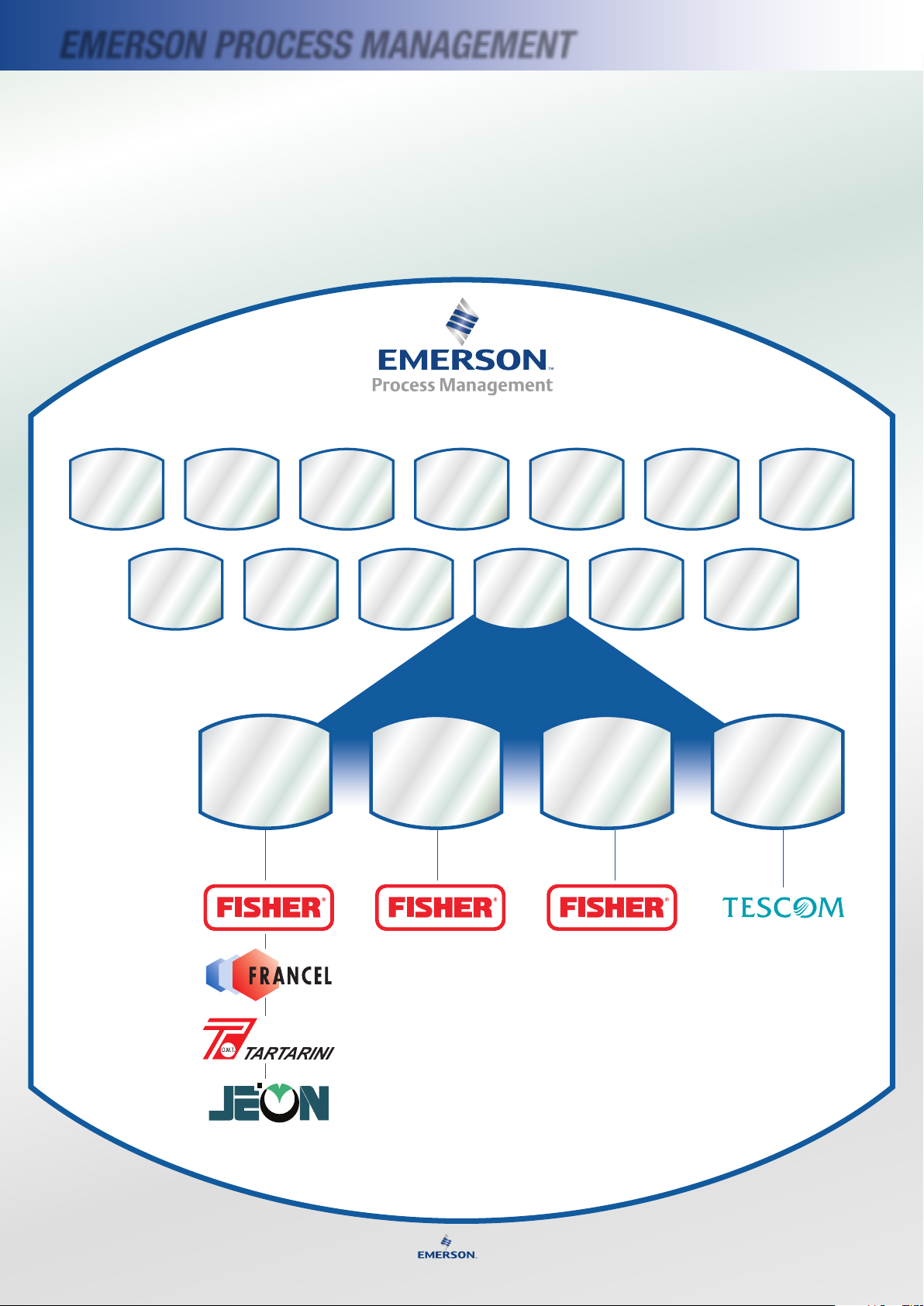
EmErsoN ProCEss mANAGEmENT
Business Units
Natural Gas
Technologies
LP-Gas
Industrial
TESCOM
Our Brands
For more information, visit www.emersonprocess.com/regulators/lp
Micro
Motion
Daniel
Asset
Optimization
Brooks
Instrument
Remote
Automation
Solutions
Process
Systems &
Solutions
Power and
Water
Solutions
Valve
Automation
Fisher
Valves
Regulator
Division
Rosemount
Rosemount
Analytical
The Divisions of Emerson Process Management
Educational
Services
Emerson Process Management
Regulator Division is a part of Emerson
Process Management, a division of Emerson
Electric. Emerson (NYSE:EMR) is a global
company that brings together technology
and engineering providing a wide range of
manufacturing and processing solutions
for industrial, commercial, and consumer
markets.
Emerson’s divisions work together
through the Emerson Brands to deliver
comprehensive customer solutions. The
Emerson divisions are: Process Management,
Network Power, Climate Technologies,
Storage Solutions, Professional Tools, Motor
Technologies, Industrial Automation, and
Appliance Solutions.
Emerson Process Management is
a leading global supplier of products,
services, and solutions that measure,
analyze, control, automate, and improve
process-related operations.
iv
Page 7
brINGING ToGETHEr TECHNoLoGy ANd ENGINEErING
Emerson Process Management offers
best-in-class measurement, analytical,
and control products and innovative
PlantWeb® architecture with a broad array
of engineering, consulting, maintenance,
and project management services.
The Emerson Process Management
organization works closely with the
Emerson process-related divisions. Strategic
acquisitions have enhanced our technology
and industry expertise. From offices, factories,
and service centers around the world, the
Emerson Process Management team now
offers unmatched capabilities to improve
process and asset performance for customers
in the chemical, oil and gas, pulp and paper,
pharmaceutical, food and beverage, power,
water and wastewater, and other process
related industries.
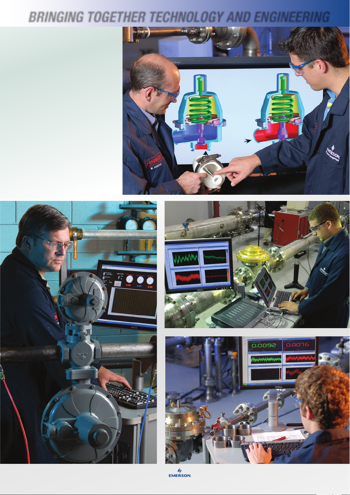
3D MoDel PrototyPe AiDs
ProDuct DeveloPMent
lAborAtory tests
siMulAte FielD
conDitions
testing
custoMer
ProDucts
Acoustic testing
oF regulAtor
Designs
v
v
Page 8
vi
THE rEGuLATor dIVIsIoN
Emerson Process Management Regulator Division, is dedicated to
serving the pressure regulator needs of process industries and natural
gas utilities and LP-gas applications worldwide.
Emerson offers pressure and flow control
solutions in three broad categories –
industrial, LP-gas and natural gas. In this
regard, Emerson offers more pressure
regulator and relief valve solutions than
any other manufacturer in the world.
With over 2,000 local technical experts
to serve you from nearly 200 locations
around the world, our sales and service
network is one of the largest in the
industry.
Whether you need an emergency
replacement regulator or are working
on a long-range growth and expansion plan, there’s a local sales
representative to respond quickly and professionally.
inDustry stAnDArDs For PerForMAnce
Our leading Fisher® brand pressure regulators and relief valves are
marketed throughout the world. Many of our regulators are industry
standards for performance and extended service life.
In recent years several companies and their product brands were added
to the Emerson pressure regulator lineup.
Francel S.A., Gallardon, France, was acquired in 1994 expanding our
distribution capabilities of regulators, relief valves, skids and cabinets
and integral slam shut devices. Fisher and Francel brand regulators are
marketed extensively in France,
and other parts of Europe,
Middle East and Africa.
Tartarini was acquired by
Emerson in the fall of 2001.
Located in Bologna, Italy,
Tartarini manufactures a full
range of regulator and slam
shut products as well as natural
gas measurement and recording
products. Tartarini brand
products extends Fisher’s brand
McKinney, texAs
Jeon, Chengdu, China, (Sichuan Province) joined Emerson in 2004.
Jeon is the leading manufacturer of natural gas regulators and systems
in China. The Jeon brand expands our presence in China’s low-pressure
regulator segment.
Tescom. Acquired in 2005, Tescom designs and manufactures high
pressure and high purity pressure regulators suitable for industrial,
pharmaceutical and semi-conductor applications. Tescom has two
manufacturing locations: Elk River, Minnesota and Selmsdorf,
Germany.
and distribution capability in
Europe and Asia.
elK river, MinnesotA
nuevo lAreDo,
Mexico
vi
chengDu, chinA
sorocAbA, brAzil
toKyo, JAPAn
Page 9

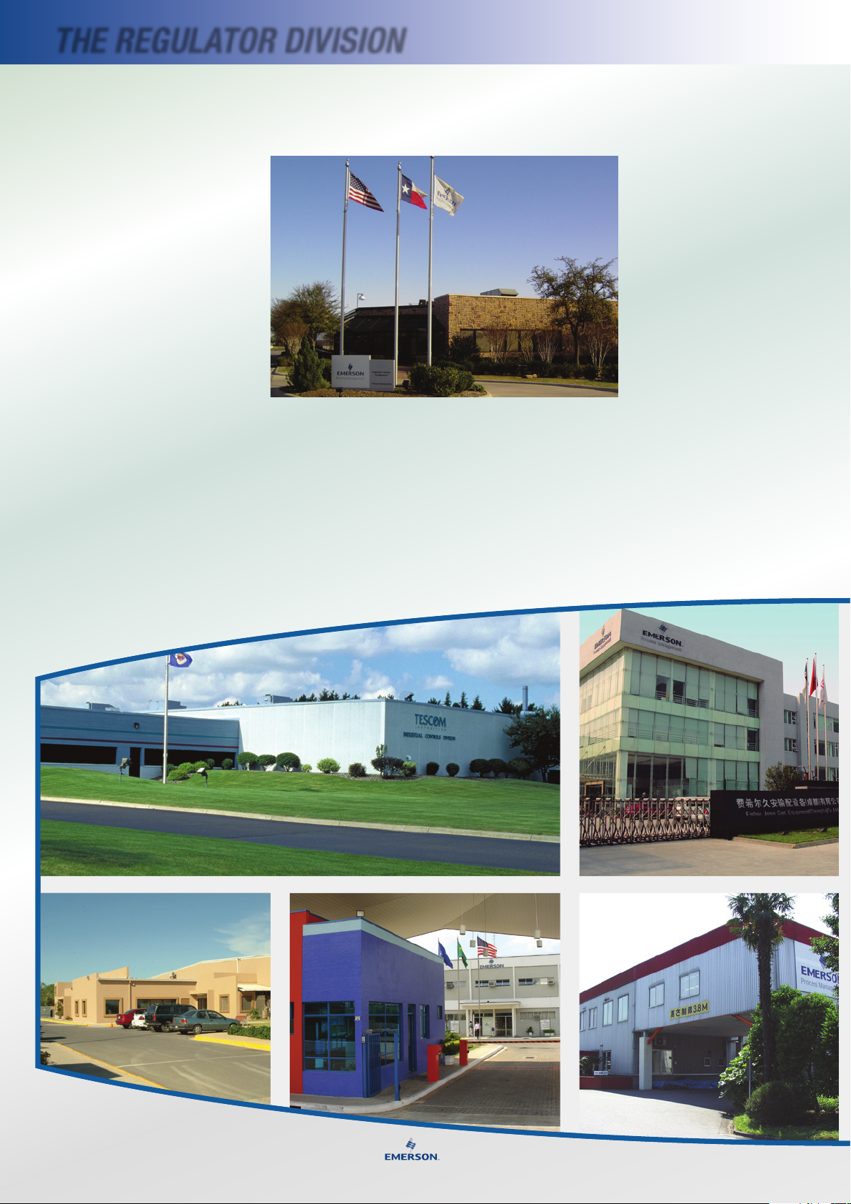
Global Manufacturing
Locations
North America
McKinney, Texas
Elk River, Minnesota
Nuevo Laredo, Mexico
South America
Sorocaba, Brazil
Europe
Gallardon, France
Bologna, Italy
Selmsdorf, Germany
Cluj, Romania
INdusTry CommITmENT
Commitment to Natural Gas, LP-Gas
and Industrial Applications
Emerson’s Regulator Division is committed to advancing
pressure regulator technology for use in natural gas, LP-gas
and industrial applications worldwide.
Our state-of-the-art Technical Center in McKinney, Texas,
is dedicated to new product development and prototype
performance testing under different sets of operating
conditions. As a result, Emerson engineers have a source
of data that is unavailable anywhere else. The R&D staff
is equally capable of simulating conditions at a customer’s
site in order to demonstrate regulator capabilities or solve a
problem.
Dynamic Flow Testing
Asia-Pacific
Shanghai, China
Chengdu, China
Singapore
Tokyo, Japan JV
Chennai, India JV
The lab contains a variety of piping for dynamic
flow testing, including four 2-inch test lines, two
4-inch test lines, and one 8-inch and one 16-inch
test line. Flow rates up to 12 Million SCFH can be
produced with precisely controlled inlet pressures.
Several temperature chambers and hydrostatic test
pumps make it possible to examine how test units
perform under extreme temperatures and pressures.
technicAl center, McKinney, texAs
(Above leFt, Above right)
bolognA, itAly
gAllArDon, FrAnceshAnghAi, chinA
singAPore
selMsDorF, gerMAny
cluJ, roMAniA
vii
vii
Page 10
HIsTory
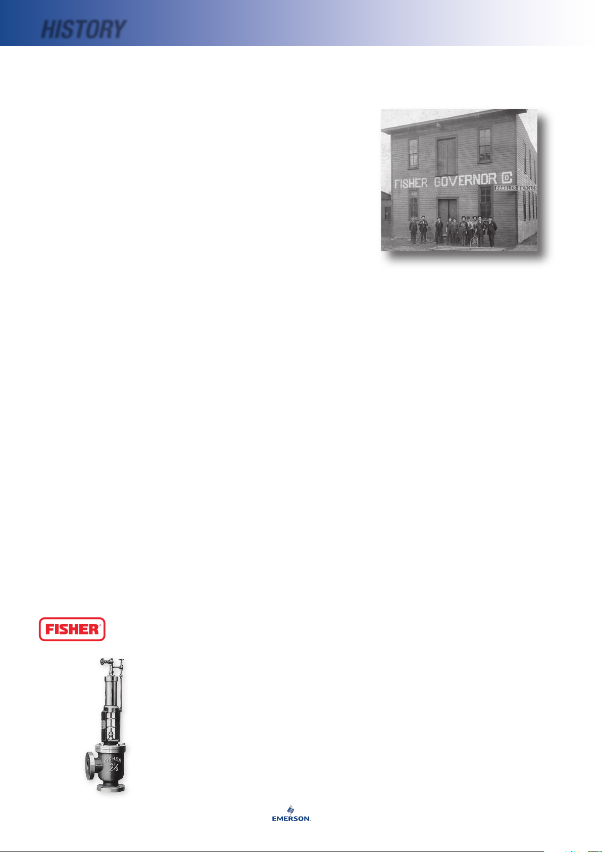
The Path To Technology Leadership
In 1880 Fisher Controls was founded in
Marshalltown, Iowa, by William Fisher.
Fisher Controls grew steadily over the years,
evolving into an industry leader offering
customers the most complete range of ow
control products in the world.
William Fisher came to America from
England as a boy of 14. As his family
ventured west in the new land, they settled
along the Mississippi in Clinton, Iowa. It
was there, as a mechanic in a small engine
shop for 10 years, that William learned about
steam, the major source of power in the late
1800s. Because of his experience in water
and steam, William, who was 24 at the time,
was invited to Marshalltown to help install
the water works.
The idea of a control device was born in the
engineer ’s mind as a re raged in the city.
Working through the night, William Fisher
hand-throttled the steam-driven pumps to
maintain pressure in the city’s mains. During
that re, he saw a need for a device that would
both control the steam-driven pumps and
maintain them at a constant pressure.
Many months and trials later, William
Fisher was nally satised with one of his
designs and began manufacturing what we
know today as the Fisher Type 1 constant
pressure pump governor. He was granted a
patent in 1884.
One thing remained the same since William
Fisher’s rst Type 1 pump governor: a pledge
to unequalled quality. Today, the brand name
Fisher is synonymous with quality throughout
the world.
Type 1 Pump
Governor 1880
The Fisher Years
1880 Type 1 pump governor is
invented by William Fisher.
1888 The Fisher Governor Company is
incorporated on Dec. 26.
1906 William Fisher dies. His wife,
Martha, becomes president.
1912 Jasper Fisher assumes
presidency; first sales offices
are established.
1937 Serial number 500,000
assigned to a Type 1 pump
governor on Nov. 5.
1938 Jasper Fisher dies.
1940 First Western Union teletype
machine is installed to speed
communication.
1943 One millionth serial number
assigned June 9.
1944 Mrs. J.H. Fisher is elected
president.
1946 Sales department holds first school for
field representatives.
1950 Two-millionth controller made. Fisher
enters licensee agreement with Elliott
Automation to manufacture products for
England and Europe.
1954 Mrs. J.H. Fisher retires; J.W. (Bill) Fisher
is elected president.
1955 New office building opens in
Marshalltown.
1960 Ball valves are added to Fisher’s product
line. Licensing agreement reached to
manufacture in Japan.
1965 Gas regulator department moves to
McKinney, Texas.
1967 Governor Road facility, the most advanced
machine shop of its kind in the world,
begins operation in Marshalltown.
1969 Fisher begins manufacturing electronic
instrumentation. Bill Fisher remains as
Chairman of the Board until 1974.
1970 Our first European facility opens at
Cornwall, England, to manufacture
electronic instrumentation.
1972 The R.A. Engel Technical Center,
Marshalltown, is completed, housing the
world’s most advanced flow test
laboratory.
1975 A new electronics manufacturing
facility is opened in Marshalltown.
1976 Production of our new line of rotary valves
begins in Sherman, Texas. Fisher Brazil
opens its doors.
1979 Fisher Controls Corporation of Delaware
forms a stronger manufacturing, sales,
and service organization.
1980 Fisher celebrates a Century of Control.
1992 ISO 9001 original registration validated,
McKinney, Texas
The Emerson Years
1993 Fisher-Rosemount formed when two
leading process instrumentation suppliers,
Fisher Controls and Rosemount, merge
under ownership of Emerson Electric.
1994 Francel, Gallardon, France, acquired,
expanding manufacturing and distribution
in Europe, Middle East and Africa.
1996 Type 299 pilot-operated regulator
introduced to natural gas market.
1997 The 50th anniversary of the Type 99.
The FloBoss 503 and Regulator Vault
are introduced.
1998 Fisher Regulators FROMEX manufacturing
plant opens in Nuevo Laredo, Mexico.
1999 Revolutionary Type EZR pressure
regulator introduced.
2001 Tartarini, Bologna, Italy, acquired, extending
Fisher’s brand and distribution capability
in Europe and Asia.
2003 Manufacturing capability expanded with
opening of Shanghai Plant.
2003 New, state-of-the-art flow test laboratory
opens in McKinney, Texas.
2004 Introduced digitally controlled odorant
injection system.
2004 Jeon, Chengdu, China, acquired,
expanding Fisher’s presence in China’s
low-pressure regulator market.
2005 125th anniversary observed in all
locations.
2005 EZ Family product lines, EZR, EZH and EZL
pressure regulators expanded.
2005 Customer Center opened to display new
regulator technology and train customers
and sales channel.
2006 Type SR stainless steel Sanitary Regulator
introduced.
2006 Tescom Corporation, Elk River, Minn.,
and Selmsdorf, Germany, manufacturer
of high-pressure, high-purity pressure
regulators, acquired.
2007 Commercial Service Regulators platform
introduced featuring True Monitor™
Protection, Slam Shut, and Secondary
Seat™ Protection options.
2007 Cluj, Romania, manufacturing location
online.
viii
Page 11
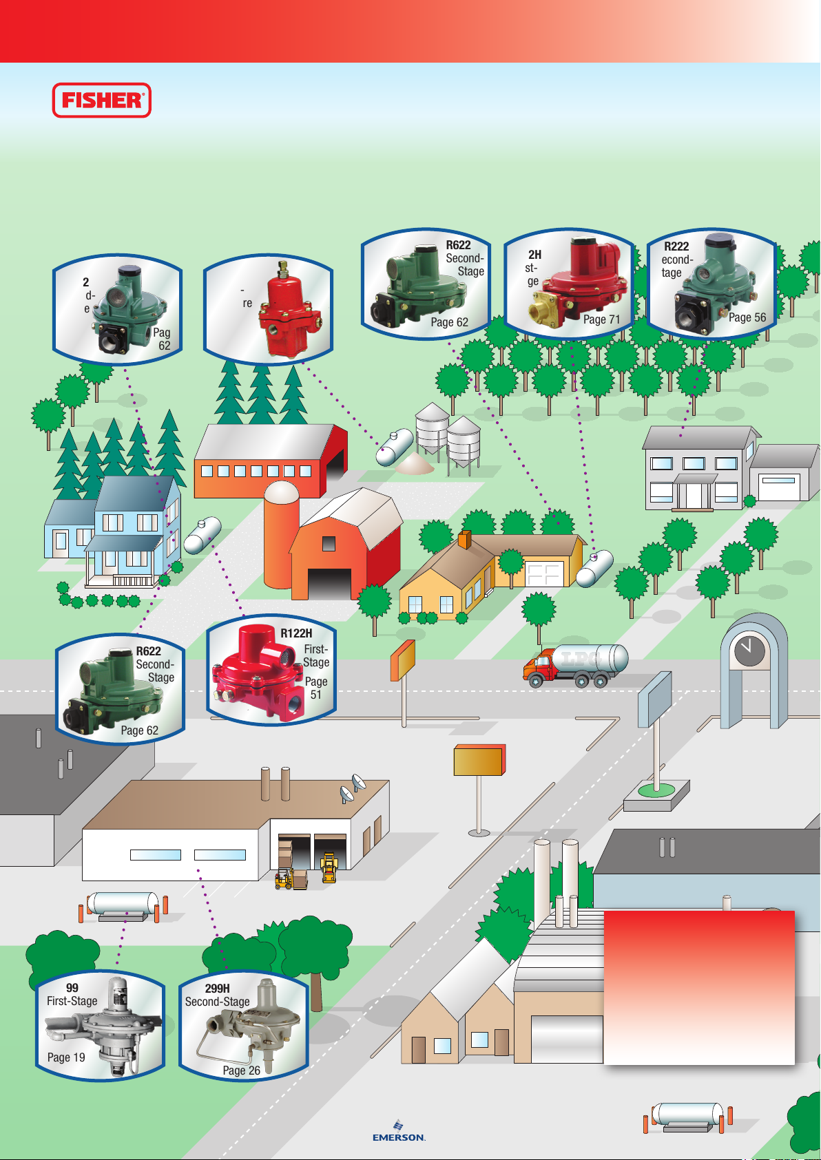
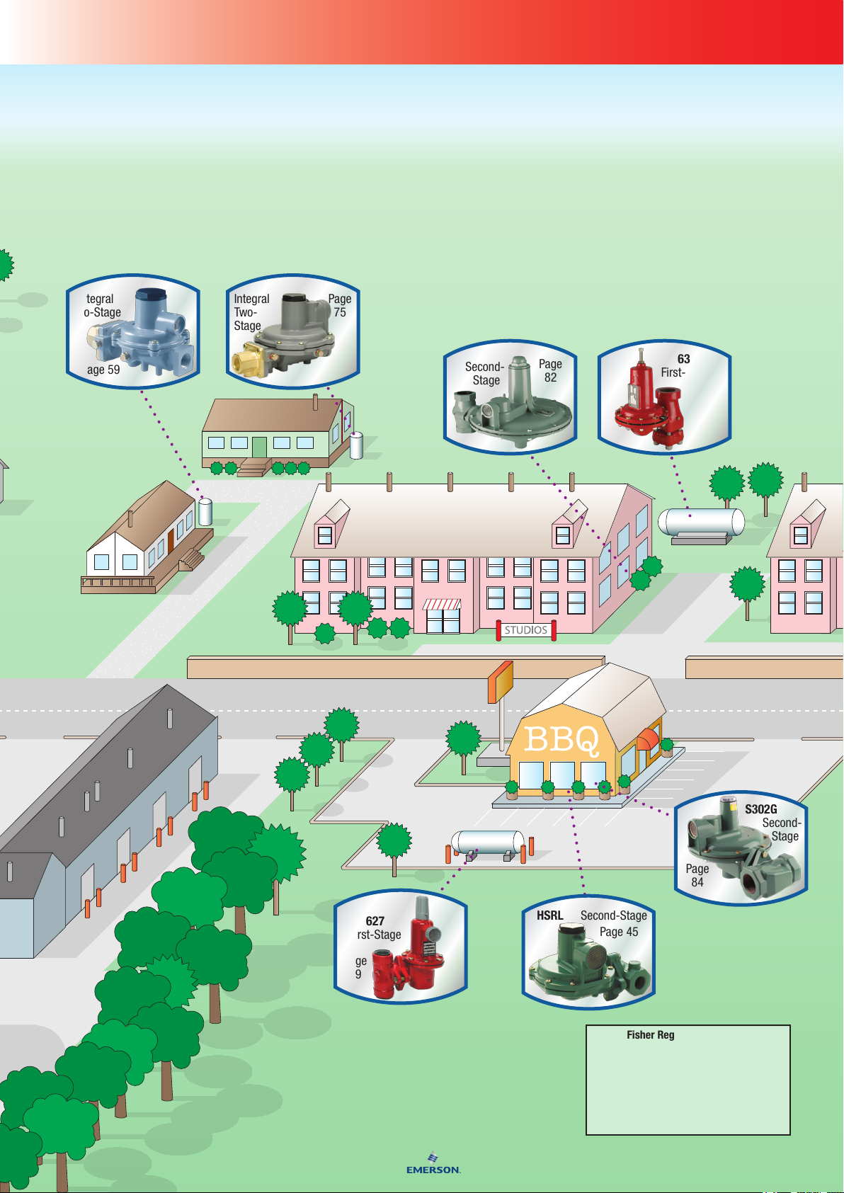
Re g u l a t o R s
LP-Gas regulators compensate for variation in tank pressure to supply
propane at a constant pressure to furnaces, burners, home appliances, farm
taps, commercial businesses, and industrial plants. The regulator must
deliver this pressure despite the intermittent use of the appliances and despite
varying flow demands.
In certain instances codes require two-stage regulation and regulator designs
are available that provide the two-stage reduction in one regulator. Many
regulators provide overpressure protection through an integrated internal
relief valve for overpressure protection, also required by some codes. Other
overpressure protection methods which are available include external relief
valves and monitors.
Page 12
R642
Second-
Stage
First-
Stage
99
First-Stage
299H
Second-Stage
R622
Second-
Stage
R622
Second-
Stage
R222
Second-
Stage
R622H
First-
Stage
67CW
High-
Pressure
Page
14
Page
62
Page
51
Page 19
Page 26
Page 62
Page 62
Page 71
Page 56
R122H
Application: Regulators
Introduction
The regulator truly is the heart of an LPGas installation. It must compensate for
variations in tank pressure from 8 to 250 psig
(0,55 to 17,2 bar) and deliver a constant outlet
pressure of LP-Gas typically at 11-inches wc
(27,4 mbar) to consuming appliances. The
Features*
• Corrosion-Resistantand
Wear-ResistantMaterials
• StainlessSteelInletScreen
• LargeDrip-LipVent
• HighCapacityRelief
• EasyInstallation
• ImprovedRegulation
• Built-inGaugeTaps
*Features Vary By Model.
Page 13
S202G
Second-
Stage
Second-Stage
627
First-Stage
630
First-Stage
R632
R232
Page
75
Page 59
Page
82
Page
31
Page
29
Page 45
Page
84
Integral
Two-
Stage
HSRL
S302G
Integral
Two-Stage
Second-
Stage
Re g u l a t o R s ap p l i c a t i o n Ma p
regulator must deliver this pressure despite
the intermittent use of the appliances.
In propane service, NFPA 58 requires TwoStage regulation on all fixed piping systems
that serve 1/2 psig (34,5 mbar) appliance
systems (normally operated at 11-inches wc
(27,4 mbar pressure). Two-Stage regulation
produces a nearly constant pressure to the
appliance and can result in a more efficient
LP-Gas operation for the dealer resulting
in less maintenance and fewer installation
call-backs.
With properly selected regulators, the
internal relief valve provides 2 psig (0,14 bar)
overpressure protection as required by
NFPA 58.
Emerson Process Management is a leading
international supplier of cost-effective
products, services, and solutions used in the
propane industry. Around the world, Fisher®
brand LP-Gas Equipment Distributors offer
quality products as well as applications
engineering, education programs and after
sales service. For any of the products
described in this handbook, contact your
local LP-Gas Equipment Distributor.
Fisher Regulator Color Code
First-Stage ........................... Red
Second-Stage ......................Palm Green
2-PSI Service .......................White*
Integral Two-Stage ...............Gray
Pounds to Pounds ................Red
Industrial .............................Black or Gray
*R622E and R652E are green with white closing caps
Page 14
4
Re g u l a t o R s Qu i c k se l e c t i o n gu i d e
COMMERCIAL/
INDUSTRIAL
HIGH PRESSURE
REGULATORS
MAXIMUM INLET
PRESSURE
250 psig
(17,2 bar)
250 psig
(17,2 bar)
300 psig
(20,7 bar)
250 psig
(17,2 bar)
250 psig
(17,2 bar)
OUTLET
PRESSURE RANGE
3 to 100 psig
(0,21 to 6,9 bar)
3 to 135 psig
(0,21 to 9,3 bar)
0.25 to 100 psig
(0,02 to 6,9 bar)
5 to 20 psig
(0,35 to 1,4 bar)
8 to 20 psig
(0,55 to 1,4 bar)
CAPACITY*
(1)
5 200 000 BTU/hr
(58,5 SCMH)
1 200 000 BTU/hr
(13,5 SCMH)
74 300 000 BTU/hr
(836 SCMH)
10 700 000 BTU/hr
(120 SCMH)
14 000 000 BTU/hr
(158 SCMH)
TYPE
NUMBER
64 Series
Page 11
67C Series
Page 14
99 Series
Page 19
627 Series
Page 29
630 Series
3-inches w.c.
150 psig
(10,3 bar)
6000 psig
(414 bar)
*See capacity tables in the following sections for expanded rating information.
1. Based on inlet pressure 20 psig (1,4 bar) greater than outlet with 20% droop, unless otherwise noted.
2. Based on 2000 psig (138 bar) inlet pressure setting.
3. Types 912-101 and -104 rating at 30 (2,1 bar) psig inlet.
to 5 psig
(7 mbar to 0,34 bar)
10 to 75 psig
(0,69 to 5,2 bar)
320 000 BTU/hr
(3,60 SCMH)
(3)
3 800 000 BTU/hr
(43,0 SCMH)
(2)
Page 31
912 Series
Page 36
Type 1301F
Page 39
Page 15

5
Re g u l a t o R s Qu i c k se l e c t i o n gu i d e
COMMERCIAL/
INDUSTRIAL
LOW PRESSURE
REGULATORS
MAXIMUM INLET
PRESSURE
150 psig
(10,3 bar)
150 psig
(10,3 bar)
25 psig
(1,7 bar)
15 psig
(1,03 bar)
OUTLET
PRESSURE RANGE
0.25 to 15 psig
(0,02 to 1,0 bar)
7-inches w.c.
to 16 psig
(17 mbar to 1,1 bar)
9 to 18-inches w.c.
(22 to 45 mbar)
6 to 14-inches w.c.
(15 to 35 mbar)
CAPACITY*
(1)
63 250 000 BTU/hr
(712 SCMH)
38 000 000 BTU/hr
(428 SCMH)
21 600 000 BTU/hr
(243 SCMH)
(3)
5 500 000 BTU/hr
(62,0 SCMH)
(3)
TYPE
NUMBER
99 Series
Page 19
299H Series
Page 26
S202G Series
Page 82
S302G Series
Page 84
MAXIMUM INLET
PRESSURE
OUTLET PRESSURE
SETTING/STANDARD
SETPOINTS
10 psig (0,69 bar)
250 psig
(17,2 bar)
FIRST-STAGE
+/- 1 psig (0,07 bar)
nominal outlet setting
(non-adjustable)
REGULATORS
5 or 10 psig
250 psig
(17,2 bar)
*See capacity tables in the following sections for expanded rating information.
1. Based on inlet pressure 20 psig (1,4 bar) greater than outlet with 20% droop, unless otherwise noted.
2. Based on 30 psig (2,1 bar) inlet pressure and 20% droop.
3. Based on 10 psig (0,69 bar) inlet pressure setting and 2-inches w.c. (5 mbar) droop.
(0,34 or 0,69 bar)
standard setpoints
CAPACITY*
(2)
1 100 000 BTU/hr
(12,4 SCMH)
2 400 000 BTU/hr
(27,0 SCMH)
TYPE
NUMBER
Type R122H
Page 51
R622H Series
Page 71
Page 16
6
Re g u l a t o R s Qu i c k se l e c t i o n gu i d e
SECOND-STAGE
REGULATORS
MAXIMUM INLET
PRESSURE
10 psig
(0,69 bar)
10 psig
(0,69 bar)
10 psig
(0,69 bar)
STANDARD
SETPOINT
9 to 13-inches w.c.
(22 to 32 mbar)
11-inches w.c.
(27 mbar)
11-inches w.c.
(27 mbar)
CAPACITY*
(1)
2 600 000 BTU/hr
(29,3 SCMH)
650 000 BTU/hr
(7,3 SCMH)
1 400 000 BTU/hr
(15,8 SCMH)
TYPE
NUMBER
Type HSRL
Page 45
R222 Series
Page 56
R622 Series
Page 62
10 psig
11-inches w.c.
(0,69 bar)
10 psig
11-inches w.c.
(0,69 bar)
*See capacity tables in the following sections for expanded rating information.
1. Based on 10 psig (0,69 bar) inlet pressure setting.
(27 mbar)
(27 mbar)
920 000 BTU/hr
(10,4 SCMH)
1 080 000 BTU/hr
(12,2 SCMH)
R642 Series
Page 62
R652 Series
Page 62
Page 17

7
Re g u l a t o R s Qu i c k se l e c t i o n gu i d e
INTEGRAL
TWO-STAGE
REGULATORS
MAXIMUM INLET
PRESSURE
250 psig
(17,2 bar)
250 psig
(17,2 bar)
STANDARD
SETPOINT
First-Stage:
Approximately
10 psig (0,69 bar)
(non-adjustable)
Second-Stage:
11-inches w.c.
(27 mbar)
First-Stage:
Approximately
10 psig (0,69 bar)
(non-adjustable)
Second-Stage:
11-inches w.c.
(27 mbar)
CAPACITY*
(1)
450 000 BTU/hr
(5,1 SCMH)
(1)
850 000 BTU/hr
(9,6 SCMH)
(1)
TYPE
NUMBER
R232 Series
Page 59
R632 Series
Page 75
MAXIMUM INLET
PRESSURE
STANDARD
SETPOINT
10 psig
(0,69 bar)
(0,14 bar)
2-PSI SERVICE
REGULATORS
10 psig
(0,69 bar)
*See capacity tables in the following sections for expanded rating information.
2. Based on 30 psig (2,1 bar) inlet pressure setting.
(0,14 bar)
2 psi
2 psi
CAPACITY*
(2)
1 680 000 BTU/hr
(18,9 SCMH)
1 500 000 BTU/hr
(16,9 SCMH)
TYPE
NUMBER
R622E Series
Page 67
Type R652E
Page 67
Page 18
8
Re g u l a t o R s Qu i c k se l e c t i o n gu i d e
AUTOMATIC
CHANGEOVER
MANIFOLD
MAXIMUM INLET
PRESSURE
250 psig
(17,2 bar)
MAXIMUM WORKING
PRESSURE
300 psig
(20,7 bar)
OUTLET PRESSURE
SETTING
15 psig (1,0 bar)
from the supply
cylinder and
7 psig (0,48 bar)
from the
reserve cylinder
RELIEF PRESSURE
RANGE
25 to 140 psig
(1,7 to 9,7 bar)
CAPACITY*
500 000 BTU/hr
(5,6 SCMH)
RELIEF
CAPACITY*
93.1GPM
(352 l/min)
Propane
TYPE
NUMBER
Type R110
Page 49
TYPE
NUMBER
98H Series
Page 17
BACKPRESSURE
REGULATORS/
25 psig
(1,7 bar)
0.5 to 2.25 psig
(0,03 to 0,16 bar)
RELIEF VALVES
150 psig
(10,3 bar)
*See capacity tables in the following sections for expanded rating information.
5 to 125 psig
(0,34 to 8,6 bar)
11 000 SCFH
(312 SCMH)
Propane
2840 SCFH
(80,4 SCMH)
Propane
289H Series
Page 23
1805 Series
Page 41
Page 19
9
Re g u l a t o R s Qu i c k se l e c t i o n gu i d e
AUTOMATIC
CHANGEOVER
REGULATOR
MAXIMUM INLET
PRESSURE
250 psig
(17,2 bar)
MAXIMUM INLET
PRESSURE
SELECTION
INFORMATION
First Stage
Regulator
Type R110
Second Stage
Regulator
R622 Series
STANDARD OUTLET
SETTING
CAPACITY*
600 000 BTU/hr
(6,8 SCMH)
CAPACITY*
TYPE
NUMBER
Type R962
Page 79
TYPE
NUMBER
CHANGEOVER
MANIFOLD
ASSEMBLIES
250 psig
(17,2 bar)
250 psig
(17,2 bar)
Supply:
15 psig (1,0 bar)
Reserve:
5 psig (0,34 bar)
Supply:
45 psig (3,1 bar)
Reserve:
30 psig (2,1 bar)
1 575 000 BTU/hr
(17,7 SCMH)
1 500 000 BTU/hr
(16,9 SCMH)
Type 749B
Page 33
Type R130
Page 54
*See capacity tables in the following sections for expanded rating information.
Page 20

Re g u l a t o R s ap p l i c a t i o n s
OVERVIEW
Emerson Process Management’s Fisher®
brand provides the most complete line of
regulators in the industry today. Pressure
reducing regulators supply LP-gas at
a constant pressure for commercial
applications such as furnaces and boilers
in industrial facilities to farm taps and
jurisdictional systems. These facilities
and systems provide several million BTU
per hour to small domestic and appliance
applications. Fisher brand regulators
are designed to the highest standards for
safe and accurate gas delivery, regardless
of variations in supply pressure. This
Application Guide briefly explains the types
of regulators available for these regulators.
Your local LP-Gas Distributor can assist
you in selecting the proper regulators and
accessories for your system.
COMMERCIAL/INDUSTRIAL HIGH- AND
LOW-PRESSURE REGULATORS
Commercial or industrial regulators are
often higher-volume devices that reduce
tank pressures of 250 psig (1,7 bar) to
pressures as low as 11-inches w.c. (water
column) (27 mbar). Flows can be as low
as 1 000 000 BTU/hr or as high as
100 000 000 BTU/hr.
FIRST-STAGE REGULATORS
A two-stage pressure-reducing regulator
system uses two regulators to cut the
supply pressure from the storage tank to
the appliance. The first-stage regulator
supplies a nearly constant inlet pressure
around 8 to 10 psig (0,55 to 0,69 bar) to
a second-stage regulator. This relative
constant pressure allows appliances to work
efficiently. To comply with requirements,
such as NFPA 58, a two-stage system is
used. The second-stage unit does not
have to compensate for widely varying
inlet pressures. The first-stage regulator
is often at the tank and the second stage at
the building or equipment being supplied.
Second-stage pressure can be adjusted as
desired. The first stage must be capable of
higher inlet pressures.
TWO-PSI REGULATORS
A two-psi pressure regulator is used as an
intermediate regulator after the first-stage
regulator. These regulators are designed for
2 psig (0,14 bar) LP-gas regulator systems.
These regulators feature a combination relief
valve and large vent that provide over pressure
protection and exceed UL requirements.
SECOND-STAGE REGULATORS
A two-stage pressure-reducing regulator
system uses two regulators to cut the
supply pressure from the storage tank to the
appliance. The two-stage system supplies
a nearly constant outlet pressure to the
appliance allowing the appliance to work
efficiently. To comply with requirements,
such as NFPA 58, a two-stage system is
used. The first-stage regulator is often at
the tank and the second stage at the building
or equipment being supplied. Second-stage
pressure can be adjusted as desired. The
second-stage regulator reduces the pressure
from a first-stage unit to 11-inches w.c.
(27 mbar) in domestic installations. Vents
are normally screened.
INTEGRAL TWO-STAGE REGULATORS
Integral two-stage regulators combine both
stages into one compact unit and are often
used for installations where piping distance
between the building being served and the tank
is short. Integral two-stage regulators provide
all the advantages of two-stage regulation.
FIVE REASONS TO USE A
TWO-STAGE SETUP
1. Ifrequiredforcompliancewithcode
requirementssuchasNFPA58.
2. Fewertroublecalls
With a two-stage system, you can expect
fewer customer trouble calls due to regulator
freeze-ups from too much water in the gas. A
two-stage regulator reduces these possibilities
in two ways: First, a larger orifice can be
used, making it more difficult for ice to
build-up and block the orifice. Second,
more heat can be transferred through the
walls of two regulators than one.
3. Smallerpipeortubing
Due to the higher pressure between the
first and second-stage units, smaller pipe or
tubing can be used in a two-stage system.
These savings can make a two-stage system
more economical to install than a singlestage system.
4. Constantappliancepressure
With a two-stage system, a first-stage
regulator supplies a nearly constant inlet
pressure of 8 to 10 psig (0,55 bar to 0,69 bar)
to a second-stage regulator. This means that
the second-stage regulator does not have to
attempt to compensate for widely varying
inlet pressures. With more uniform pressure,
appliances work better, and customers are
less likely to experience problems that result
in service calls.
5. Keepdownstreampressurebelow
2psig(0,14bar)
Second-stage and Integral two-stage
regulators have internal pressure relief
valves, which limit the outlet pressure
to 2 psig (0,14 bar) when the seat disc is
removed and the inlet pressure is 10 psig
(0,69 bar) or less as specified in UL 144,
STANDARD for LP-GAS REGULATORS.
WHEN TO USE A TWO-STAGE SETUP
Emerson Process Management recommends
Fisher brand two-stage systems whenever
the following conditions exist:
1. Compliancewithregulationcodes.
2. Thereisapossibilityofmoisturein
theLP-gas.
3. Widefluctuationsingasdemandexist.
4. Winterandsummertemperatures
varygreatly.steamheader.
10
Page 21

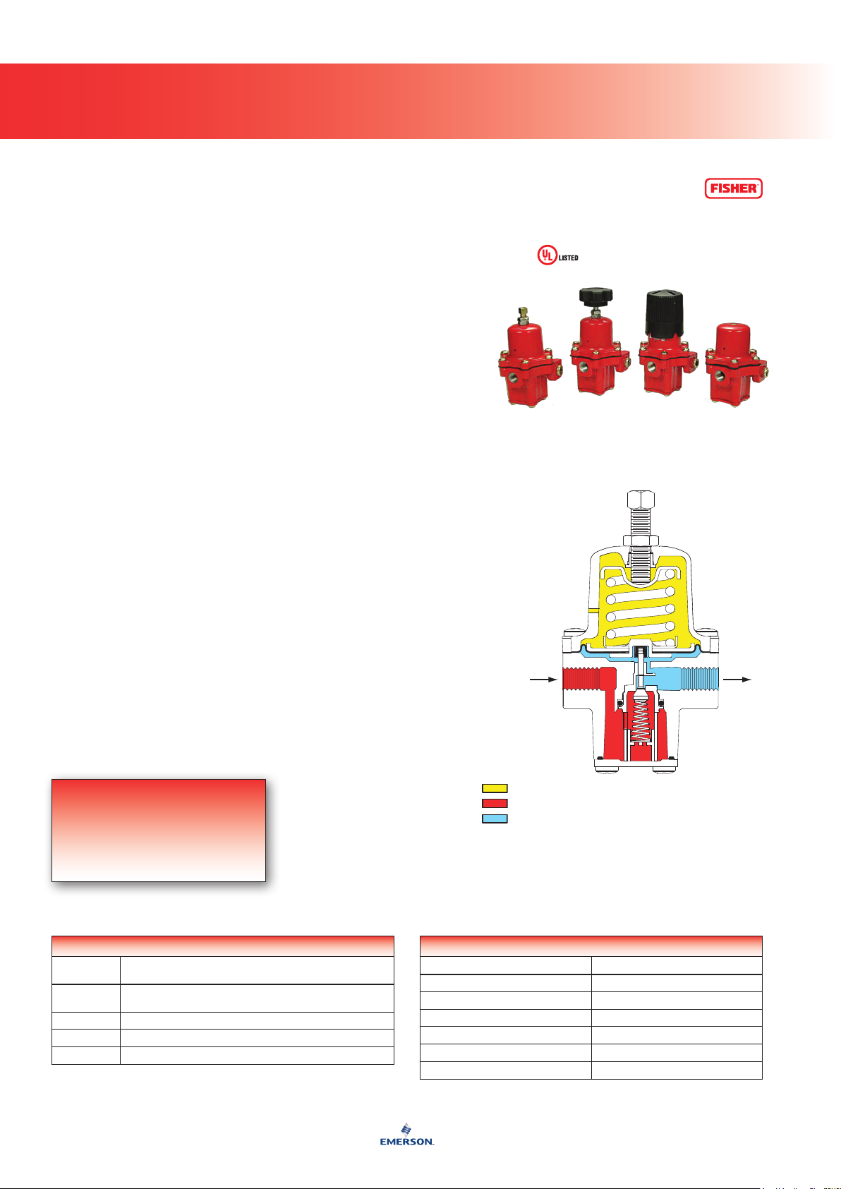
64 Series High Pressure Regulators
Re g u l a t o R s
Introduction
The 64 Series adjustable high-pressure
regulators offer a wide range of available
pressure ranges. High-pressure regulators
usually reduce tank pressure to an
intermediate pressure for use by another
regulator. They may be used as highpressure regulators on distribution systems
when used in conjunction with rst-stage
downstream regulators.
When equipped with an internal relief valve
(64SR Series), the regulator may be used as a
nal-stage regulator on high-pressure systems.
It may also be used as a rst-stage regulator
when set at 10 psig (0,69 bar) or less.
The 64KB Series has a special
Polytetrauoroethylene (PTFE) diaphragm
protector that makes it suitable for anhydrous
ammonia (NH3) service. The 1/4-inch FNPT
tapped and plugged side outlet can be used
to install a pressure gauge or a hydrostatic
relief valve.
Body Size and End Connection Style
End:1/2-inch threaded NPT
SideOutlet: 1/4-inch threaded NPT
Spring Case Vent
1/4-inch threaded NPT with screen
Temperature Capabilities
-20° to 150°F (-29° to 66°C)
Maximum Inlet Pressure
250 psig (17,2 bar)
Maximum Emergency Outlet Pressure
The value of 220 psig (15,2 bar) is designated
strictly for emergency outlet pressure and not for
maximum outlet (operating) pressure. This should
be incorporated to distinguish safety pressures from
operating pressures.
Outlet Pressure Ranges
3 to 100 psig (207 mbar to 6,9 bar)
in four ranges
See Table 1
Flow Coefficient
Wide-OpenCg: 35.6
Additional Technical Data
For more technical information,
contact your local LP-Gas
Equipment Distributor or log on to:
www.emersonprocess.com/regulators/lp
P1027
Figure 1. 64 Series High Pressure Regulator
Features
• Versatility
• BodySideConnection
• EasyMaintenance
• ULListed
Table 1. Outlet Pressure Ranges
OUTLET PRESSURE RANGE,
PSIG (bar)
3 to 15 (207 mbar to 1,0 bar) 1D892327022 Red
5 to 35
(0,3 to 2,4)
30 to 60
(2,1 to 4,1)
35 to 100
(2,4 to 6,9)
SPRING PART
NUMBER
1D665927022
1D745527142
1E543627142
SPRING
COLOR
Blue
Green
Yellow
INLET PRESSURE
OUTLET PRESSURE
ATMOSPHERIC PRESSURE
M1020
Figure 2. Operational Schematic
11
Page 22
64 Series High Pressure Regulators
12
Re g u l a t o R s
Table 2. Construction Materials
BODY
Die-cast
aluminum
REGULATOR
SPRING
Steel
SPRING CASE
Die-cast
aluminum
Table 3. Capacities
Outlet Pressure Setting Spring Range Capacity in BTU/hr (SCMH) of Propane
10 psig (0,69 bar) 3 to 15 psig (0,21 to 1,0 bar) 2 625 000 (29,6)
20 psig (1,4 bar) 5 to 35 psig (0,34 to 2,4 bar) 3 600 000 (40,5)
40 psig (2,8 bar) 30 to 60 psig (2,1 to 4,1 bar) 4 150 000 (46,7)
50 psig (3,4 bar) 35 to 100 psig (2,4 to 6,9 bar) 5 250 000 (59,1)
Outlet Pressure Setting Spring Range Capacity in BTU/hr (SCMH) of Propane
10 psig (0,69 bar) 3 to 15 psig (0,21 to 1,0 bar) 2 625 000 (29,6)
15 psig (1,0 bar) 5 to 20 psig (0,34 to 1,4 bar) 3 000 000 (33,8)
20 psig (1,4 bar) 5 to 35 psig (0,34 to 2,4 bar) 3 600 000 (40,5)
Outlet Pressure Setting Spring Range Capacity in SCFH (SCMH) of Ammonia
10 psig (0,69 bar) 3 to 15 psig (0,21 to 1,0 bar) 1650 (46,7)
15 psig (1,0 bar) 5 to 20 psig (0,34 to 1,4 bar) 2050 (58,0)
20 psig (1,4 bar) 5 to 35 psig (0,34 to 2,4 bar) 2250 (63,7)
40 psig (2,8 bar) 30 to 60 psig (2,1 to 4,1 bar) 2600 (73,6)
50 psig (3,4 bar) 35 to 100 psig (2,4 to 6,9 bar) 3300 (93,4)
1. Based on inlet pressure 20 psig (1,4 bar) greater than outlet with 20% droop.
2. Capacity based on 20 psig (1,4 bar) above setpoint and 20% droop.
3. Metric conversion is based on 2516 BTU/ft3 of gas at 60°F (16°C).
64 SERIES
64SR SERIES
64KB SERIES
STEM GUIDE AND
DISK HOLDER
Stainless steel Nitrile (NBR) Stainless steel
DIAPHRAGM VALVE STEM
(1)(3)
(1)(3)
(2)
Page 23

64 Series High Pressure Regulators
13
Re g u l a t o R s
1/4-INCH NPT
SCREENED VENT
B
A
(MAXIMUM)
1/2-INCH NPT
1/4-INCH NPT SIDE OUTLET
A0813_1
C
D
Figure 3. Dimensions
Table 4. Dimensions and Approximate Weight
DIMENSIONS, INCHES (mm)
A B C D
8.25 (209) 4.12 (105) 2.75 (69,9) 1.56 (39,6) 2.25 (1,02)
Ordering Guide
Ordering Information
TYPE NUMBER DESCRIPTION
64-33
64-35 20 (1,38) 5 to 35 (0,35 to 2,41)
64-36 40 (2,76) 30 to 60 (2,07 to 4,14)
64-222 50 (3,45) 35 to 100 (2,41 to 6,90)
64SR-21
64SR-22 15 (1,03) 5 to 20 (0,35 to 1,38)
64SR-23 20 (1,38) 5 to 35 (0,35 to 2,41)
64SR-122 10 (0,69) 5 to 20 (0,35 to 1,38)
64KB-33
64KB-34 15 (1,03) 5 to 20 (0,35 to 1,38)
64KB-35 20 (1,38) 5 to 35 (0,35 to 2,41)
64KB-36 40 (2,76) 30 to 60 (2,07 to 4,14)
64KB-222 50 (3,45) 35 to 100 (2,41 to 6,90)
Basic Regulator
With Internal Relief Valve
With Special Diaphragm Protector
OUTLET PRESSURE SETTING,
PSIG (bar)
10 (0,69) 3 to 15 (0,21 to 1,03)
10 (0,69) 3 to 15 (0,21 to 1,03)
10 (0,69) 3 to 15 (0,21 to 1,03)
OUTLET ADJUSTMENT RANGE,
PSIG (bar)
APPROXIMATE WEIGHT,
POUNDS (kg)
INLET AND OUTLET
CONNECTIONS, INCHES
1/2 FNPT
To order, refer to the Ordering Information table above and specify the type number that satises your requirement.
Then, contact or visit your local LP-Gas Equipment Distributor for availability.
Page 24
67C Series High Pressure Regulators
14
Re g u l a t o R s
Introduction
The 67C Series is a Underwriters
Laboratories (UL) listed high-pressure
regulators that meets a variety of
applications in liquid or vapor service.
The compact body design makes the
67C Series particularly useful in
installations with space limitations.
The basic 67C Series regulators come
equipped with a wrench or handwheel
adjustment (67CW or 67CH Series). The
highly accurate 67CD Series eliminates
the need for a pressure gauge on portable
applications by using calibrated scales on
the spring case, allowing visual adjustment
of outlet pressure. The non-adjustable
67CN Series provides a tamper-resistant
spring case and one of three xed setpoints:
10, 15, or 20 psi (0,69; 1,0; or 1,4 bar).
The 67C Series carries a UL listing as a
high pressure, non-relief regulator. This
series contains brass materials that are not
compatible with anhydrous ammonia service.
Body Size and End Connection Style
1/4-inch FNPT
Side Outlet Connection Style (Plugged)
1/4-inch threaded NPT; pressure gauge
(J500 Series) can be installed
Maximum Inlet Pressure (Body Rating)
250 psig (17,2 bar)
Maximum Emergency Outlet Pressure
50 psig (3,4 bar) over outlet pressure
Pressure Registration
Internal
Spring Case Vent Location
Aligned with inlet, other position optional
Flow Coefficient
Wide-OpenCgforReliefSizing: 11.7
Temperature Capabilities
-20° to 180°F (-29° to 82°C)
Approximate Weights
Type67CW: 0.7 pound (0,32 kg)
Type67CH: 1 pound (0,45 kg)
Type67CD: 0.8 pound (0,36 kg)
Type67CN: 1.1 pound (0,50 kg)
Option
• Outlet Pressure Gauge
Additional Technical Data
For more technical information,
contact your local LP-Gas
Equipment Distributor or log on to:
www.emersonprocess.com/regulators/lp
Figure 1. 67C Series Regulators
Features
• Compact
• HighStability
• ULListed
• DurablePowderPaintCoating
Table 1. Available Congurations
TYPE
NUMBER
67CW
67CH Basic regulator with handwheel adjustments.
67CD Basic regulator with dial cap adjustments.
67CN Basic regulator, factory set with no eld adjustments.
Basic regulator with wrench adjustment and 4 spring ranges from
DESCRIPTION
3 to 135 psig (0,2 to 9,3 bar) no relief.
ATMOSPHERIC PRESSURE
INLET PRESSURE
OUTLET PRESSURE
W8442
Figure 2. Operational Schematic
Table 2. Construction Materials
PART NAME MATERIAL
Body Aluminum
Valve Stem Brass
Spring Music wire
Valve Plug Nitrile (NBR)
O-Ring and Soft Seats Nitrile (NBR)
Diaphragm Nitrile (NBR) / Nylon (PA)
Page 25
67C Series High Pressure Regulators
15
Re g u l a t o R s
Table 3. Spring Ranges and Factory Setpoints
SPRING RANGE,
3 to 20 (0,2 to 1,4) Green Stripe GE07809T012 15 (1,0) N/A
5 to 35 (0,3 to 2,4) Silver T14059T0012 20 (1,4) 10, 15, or 20 psi (0,69; 1,0; or 20 bar)
20 to 50 (1,4 to 3,4) Blue Stripe T14058T0012 40 (2,8) Type 67CD only N/A
30 to 60 (2,1 to 4,1) Blue Stripe T14058T0012 40 (2,8) Types 67CW and 67CH only N/A
35 to 100 (2,4 to 6,9) Red Stripe T14060T0012 50 (3,4) Type 67CD only N/A
35 to 135 (2,4 to 9,3) Red Stripe T14060T0012 50 (3,4) Types 67CW and 67CH only N/A
1. All springs can be backed off to 0 psig (0 bar) except Type 67CN. However, for the highest capacity and most control, use the lowest spring that can be adjusted to the
required setpoint.
PSIG (bar)
(1)
SPRING COLOR CODE SPRING PART NUMBER
Types 67CW, 67CD, and 67CH Type 67CN
TYPE AND FACTORY SETPOINT, PSIG (bar)
Table 4. Capacities
OUTLET PRESSURE SETTING, SPRING RANGE INLET PRESSURE CAPACITIES IN BTU/hr (SCMH) PROPANE
Type 67CW or 67CH
15 psig (1,0 bar) setting
3 to 20 psig (0,2 to 1,4 bar)
20 psig (1,4 bar) setting
5 to 35 psig (0,3 to 2,4 bar)
40 psig (2,8 bar) setting
30 to 60 psig ( 2,1 to 4,1 bar)
50 psig (3,4 bar) setting
35 to 135 psig (2,4 to 9,3 bar)
15 psig (1,0 bar) setting
5 to 20 psig (0,3 to 1,4 bar)
40 psig (2,8 bar) setting
20 to 50 psig (1,4 to 3,4 bar)
50 psig (3,4 bar) setting
35 to 100 psig (2,4 to 6,9 bar)
10 psig (0,7 bar)
Non-adjustable
15 psig (1,0 bar)
Non-adjustable
20 psig (1,4 bar)
Non-adjustable
1. Capacities are based on inlet pressure 20 psig (1,4 bar) greater than outlet with 20% droop.
2. Metric conversion is based on 2516 BTU/ft3 of gas at 60°F (16°C).
35 psig (2,4 bar) 675 000 (7,60)
40 psig (2,8 bar) 750 000 (8,44)
60 psig (4,1 bar) 1 200 000 (13,5)
70 psig (4,8 bar) 1 000 000 (11,3)
Type 67CD
35 psig (2,4 bar) 675 000 (7,60)
60 psig (4,1 bar) 1 200 000 (13,5)
70 psig (4,8 bar) 1 000 000 (11,3)
Type 67CN
30 psig (2,1 bar) 400 000 (4,50)
35 psig (2,4 bar) 600 000 (6,75)
40 psig (2,8 bar) 750 000 (8,44)
(1)(2)
Page 26

Re g u l a t o R s
IN
OUT
IN
OUT
IN
OUT
67C Series High Pressure Regulators
3.95
(100)
1.51
(38)
2.56
(65)
5.50
(140)
2.92
(74)
1.46
(37)
67CD SERIES WITH
OPTIONAL GAUGE
OPTIONAL
GAUGE
SIDE OUTLET
1/4-INCH NPT
4.01
(102)
1.51
(38)
2.56
(65)
67CH SERIES WITH
OPTIONAL GAUGE
2.92
(74)
1.46
(37)
5.50
(140)
3.24
(82)
OPTIONAL
GAUGE
SIDE OUTLET
1/4-INCH NPT
Figure 3. Dimensions
1.51
(38)
2.56
(65)
67CW SERIES WITH
OPTIONAL GAUGE
2.92
(74)
1.46
(37)
5.50
(140)
OPTIONAL
GAUGE
SIDE OUTLET
1/4-INCH NPT
0.50
(12,7)
67CN SERIES
2.29
(58)
1.51
(38)
INCHES
(mm)
Ordering Guide
Ordering Information
ADJUSTMENT STYLE
AND TYPE NUMBER
Wrench Handwheel - - - - - - - -
67CW-683 67CH-751 15 (1,0) 3 to 20 (0,2 to 1,4)
67CW-684 67CH-743 20 (1,4) 3 to 35 (0,2 to 2,4)
67CW-685 67CH-742 40 (2,8) 30 to 60 (2,1 to 4,1)
67CW-701 67CH-741 50 (3,4) 50 to 135 (3,4 to 9,3)
Dial Cap - - - - - - - -
67CD-100 15 (1,0) 5 to 20 (0,3 to 1,4)
67CD-102 40 (2,8) 20 to 50 (1,4 to 3,4)
67CD-103 50 (3,4) 40 to 100 (2,8 to 6,9)
Non-Adjustable - - - - - - - -
67CN-106 10 (0,7)
67CN-105 20 (1,4)
To order, refer to the Ordering Information table above and specify the type number that satises your requirement.
Then, contact or viisit your local LP-Gas Equipment Distributor for availability.
OUTLET PRESSURE SETTING,
PSIG (bar)
SPRING RANGE,
PSIG (bar)
Non-Adjustable67CN-104 15 (1,0)
BODY AND END
CONNECTION SIZE
1/4-inch FNPT
16
Page 27

98H Series Backpressure Regulators/Relief Valves
A6925
Type 98H
COMP
Type 98H
A6925
INLET PRESSURE
OUTLET PRESSURE
ATMOSPHERIC PRESSURE/LOADING PRESSURE
January 2007
Type 98H
COM P
Re g u l a t o R s
Introduction
The 98H Series, liquid service valves are
direct-operated relief valves for use on relief
and backpressure applications involving
large LP-Gas pumping systems and
vaporizers. Internal pressure registration
eliminates the need for a control line.
Body Sizes and End Connection Style
1/2, 3/4, and 1-inch FNPT
Pressure Registration
Internal
Flow Capacities
See Table 3
Features
• Versatility
• Compact,RuggedDesign
• InternalRegistration
Maximum Relief (Inlet) Pressure
300 psig (20,7 bar)
Relief Pressure Ranges
See Table 2
Temperature Capabilities
-20° to 150°F (-29° to 66°C)
Additional Technical Data
For more technical information,
contact your local LP-Gas
Equipment Distributor or log on to:
www.emersonprocess.com/regulators/lp
W6155
Figure 1. Type 98H Backpressure/Relief Valve
BODY SIZE,
INCH FNPT
TYPE NUMBER
Table 1. Construction Materials
PART NAME MATERIAL
Body, Spring case Cast iron
Orice, O-ring retainer, Valve plug,
Valve plug guide, Pusher post
Diaphragm retaining washer 316 Stainless steel
Diaphragm Neoprene
O-ring seat Nitrile (NBR)
416 Stainless steel
INLET PRESSURE
OUTLET PRESSURE
ATMOSPHERIC PRESSURE
A6925
Figure 2. Operational Schematic
Table 2. Relief Pressure Ranges
1/2
3/4 or 1
RELIEF PRESSURE RANGES,
PSIG (bar)
25 to 75 (1,7 to 5,2) 1D7455T0012 Green Stripe 0.234 (5,94) 2.0 (50,8)
70 to 140 (4,8 to 9,7) 1E395727192 Black Stripe 0.281 (7,14) 1.94 (49,3)
25 to 75 (1,7 to 5,2) 1E399027142 Black 0.343 (8,71) 4.00 (102)
70 to 140 (4,8 to 9,7) 1E399127162 Red 0.406 (10,3) 4.00 (102)
PART NUMBER COLOR CODE
WIRE DIAMETER,
INCHES (mm)
FREE LENGTH,
INCHES (mm)
Table 3. Capacities
PROPANE RELIEF CAPACITY IN GALLONS PER MINUTE (l/min)
RELIEF PRESSURE
SETTING, PSIG (bar)
98H-13 50 (3,4) 25 to 75 (1,7 to 5,2) 10.5 (39,7) 15.4 (58,3) 21.7 (82,1) 25.9 (98,0) 30.8 (117)
98H-14 100 (6,9) 70 to 140 (4,8 to 9,7) 8.4 (31,8) 15.4 (58,3) 27.3 (103) 32.9 (125) 39.2 (148)
98H-22 100 (6,9) 70 to 140 (4,8 to 9,7) 30.8 (117) 49 (185) 67.9 (257) 79.8 (302) 93.1 (352)
98H-30 100 (6,9) 70 to 140 (4,8 to 9,7) 30.8 (117) 49 (185) 67.9 (257) 79.8 (302) 93.1 (352)
RELIEF PRESSURE
RANGE, PSIG (bar)
5 Psig
(0,34 bar)
AT FOLLOWING PRESSURE BUILD-UP OVER RELIEF SETTING
10 Psig
(0,69 bar)
20 Psig
(1,4 bar)
30 Psig
(2,1 bar)
50 Psig
(3,4 bar)
17
Page 28
Re g u l a t o R s
98H Series Backpressure Regulators/Relief Valves
D
1/4-INCH NPT
C
NPT
B
A/2
A
B2557
Figure 3. Dimensions
Table 4. Dimensions and Approximate Weights
TYPE
NUMBER
98H
BODY SIZE,
INCHES
1/2
3/4 or 1
A B
4.25 (108)
5.00 (127)
DIMENSIONS, INCHES (mm)
0.88 (22)
1.25 (32)
C
(Maximum)
7.19 (183)
9.69 (246)
D
4.25 (108)
6.06 (154)
Ordering Guide
Ordering Information
TYPE NUMBER BODY SIZE AND END CONNECTION STYLE RELIEF PRESSURE RANGE, PSIG (bar) DIAPHRAGM MATERIAL
98H-13
98H-14 70 to 140 (4,8 to 9,7)
98H-17 25 to 75 (1,7 to 5,2)
98H-18 70 to 140 (4,8 to 9,7)
98H-22 3/4-inch FNPT 70 to 140 (4,8 to 9,7)
98H-31 130 to 200 (9,0 to 13,8)
1/2-inch FNPT
1-inch FNPT
25 to 75 (1,7 to 5,2)
70 to 140 (4,8 to 9,7)
Neoprene (CR)
302 Stainless steel
Neoprene (CR)98H-30
APPROXIMATE
WEIGHTS,
POUNDS (kg)
7 (3,18)
16 (7,26)
18
To order, refer to the Ordering Information table above and specify the type number that satises your requirement.
Then, contact or visit your local LP-Gas Equipment Distributor for availability.
Page 29
99 Series Commercial/Industrial Regulators
Re g u l a t o R s
Introduction
The 99 Series commercial/industrial
regulator is a pilot-operated unit that keeps
outlet pressure constant despite varying
ow rates and inlet pressures. It can
be used for either low or high-pressure
applications while maintaining accuracy.
Ease of maintenance is only one of the
many features of the 99 Series. The
actuator diaphragm and pilot respond
simultaneously to control nal positioning
of the main valve, permitting full main
valve travel and higher capacity capabilities.
Body Size and End Connection Style
2-inch threaded NPT
Maximum Inlet Pressures
See Table 3
Features
• Versatility
• BodySideConnection
• EasyMaintenance
• HighCapacityPressureControl
• RuggedConstruction
Maximum Outlet (Casing) Pressure
100 psig (6,9 bar)
Outlet Pressure Ranges
See Table 2
Maximum Actuator Pressures
Operating: 100 psig (6,9 bar)
Emergency: 110 psig (7,6 bar)
Orifice Size
7/8 or 1-1/8-inch (22,2 or 28,6 mm)
Temperature Capabilities
-20° to 180°F (-29° to 82°C)
Pressure Registration
External
Approximate Weight
115 pounds (52 kg)
Additional Technical Data
For more technical information,
contact your local LP-Gas
Equipment Distributor or log on to:
www.emersonprocess.com/regulators/lp
W2676
Figure 1. 99 Series Commercial/Industrial Regulator
Table 1. Construction Materials
BODY
Cast iron Cast iron
SPRING CASE AND
DIAPHRAGM CASE
DIAPHRAGMS AND MAIN
VALVE SEAT DISK
Nitrile (NBR), Neoprene,
and Nylon
MAIN VALVE TRIM PILOT TRIM TUBING AND FITTINGS
Brass
Steel, Stainless steel,
Cast iron, Aluminum, Zinc,
or Brass
Table 2. Outlet Pressure Ranges
PILOT TYPE
(1)
61LD
(2)
61LE
61HP 600 (41) 35 to 100 (2,4 to 6,9) 1D387227022 Blue 0.200 (0,51) 1.69 (4,3)
1. Type 61LD construction has narrower proportional band than does the standard Type 61L Pilot.
2. Type 61LE construction has broader proportional band than does the standard Type 61L Pilot.
MAXIMUM PILOT
SUPPLY PRESSURE,
PSIG (bar)
160 (11,0)
400 (27,6)
OUTLET (CONTROL)
PRESSURE RANGES,
PSIG (bar)
0.25 to 2
(17 to 138 mbar)
1 to 5
(69 mbar to 0,3 bar)
2 to 10
(138 mbar to 0,7 bar)
5 to 15
(0,3 to 1,0)
10 to 20
(0,7 to 1,4)
Part Number Color Code
1B886327022
1J857827022
1B886427022
1J857927142
1B886527022
PILOT CONTROL SPRING
Wire Diameter,
Inches (cm)
Red
Yellow
Blue
Brown
Green
0.109
0.142
0.172
0.187
0.363
(0,28)
(0,36)
(0,44)
(0,48)
(0,92)
Copper and Brass
Free Length,
Inches (cm)
2.75
(7,0)
2.75
(7,0)
2.87
(7,3)
2.87
(7,3)
3.12
(7,9)
19
Page 30

99 Series Commercial/Industrial Regulators
20
Re g u l a t o R s
Type 99
INWLET PRESSURE
OUTLET PRESSURE
ATMOSPHERIC PRESSURE
LOADING PRESSURE
A6469
Figure 2. Operational Schematic
Table 3. Selected Capacities
PILOT TYPE TYPE NUMBER SPRING RANGE, PSIG (bar)
99-501P 0.25 to 2 (0,02 to 0,14)
Low Pressure
High Pressure
1. Capacity based on inlet pressure 20 psig (1,4 bar) greater than outlet pressure and 20% droop.
2. Metric conversion is based on 2516 BTU/ft3 of gas at 60°F (16°C).
99-502P 1 to 5 (0,07 to 0,34) 50 600 000 (570)
99-503P 2 to 10 (0,14 to 0,69) 61 650 000 (694)
99-504P 5 to 15 (0,34 to 1,0) 63 250 000 (712)
99-510P 0.25 to 2 (0,02 to 0,14)
99-511P 1 to 5 (0,07 to 0,34) 33 206 000 (374)
99-512P 5 to 15 (0,34 to 1,0) 37 950 000 (427)
99-513P 2 to 10 (0,14 to 0,69) 36 368 000 (409)
99-515P 10 to 20 (0,69 to 1,4) 41 112 000 (463)
99-903P 10 to 65 (0,69 to 4,5) 44 275 000 (498)
99-502PH 1 to 5 (0,07 to 0,34)
99-503PH 2 to 10 (0,14 to 0,69) 61 668 000 (694)
99-504PH 5 to 15 (0,34 to 1,0) 63 250 000 (712)
99-505PH 10 to 20 (0,69 to 1,4) 67 993 000 (765)
99-901PH 10 to 65 (0,69 to 4,5) 74 318 000 (837)
ORIFICE SIZE,
INCHES (mm)
1-1/8 (29) 150 (10,3)
7/8 (22) 250 (17,2)
1-1/8 (29) 300 (20,7)
MAXIMUM INLET
PRESSURE,
(1)(2)
PSIG (bar)
CAPACITIES IN PROPANE,
BTU/hr (SCMH)
49 000 000 (552)
29 400 000 (331)
50 600 000 (570)
Page 31

99 Series Commercial/Industrial Regulators
21
Re g u l a t o R s
9.75
(248)
15.25
(387)
MAXIMUM
6.12
(155)
1.44 (37)
RAINPROOF VENT
1/4-INCH NPT
19.25
(489)
13.12
(333)
21.12
(536)
5.25
(133)
Figure 3. Dimensions
1/2-INCH NPT ALTERNATIVE
PLUGGED CONTROL
CONNECTION
10.4
(264)
1/2-INCH NPT
CONTROL CONNECTION
3.03
(77)
6.06
(154)
12.25
(311)
INCHES
(mm)
Regulator Tip
All regulators should be installed and used in accordance with federal, state, and local codes and regulations.
Page 32

Re g u l a t o R s
99 Series Commercial/Industrial Regulators
Ordering Guide
Ordering Information
TYPE NUMBER
99-501P
99-501PM Monitor Regulator
99-502P Regulator
99-502PM Monitor Regulator
99-502PH Regulator
99-502PHM Monitor Regulator
99-502PHO Regulator
99-502PHOM Monitor Regulator
99-503P Regulator
99-503PM Monitor Regulator
99-503PH Regulator
99-503PHM Monitor Regulator
99-503PHO Regulator
99-503PHOM Monitor Regulator
99-504P Regulator
99-504PM Monitor Regulator
99-504PH Regulator
99-504PHM Monitor Regulator
99-504PHO Regulator
99-504PHOM Monitor Regulator
99-505P Regulator
99-505PM Monitor Regulator
99-505PH Regulator
99-505PHM Monitor Regulator
99-505PHO Regulator
99-505PHOM Monitor Regulator
99-510P Regulator
99-510PM Monitor Regulator
99-511P Regulator
99-511PM Monitor Regulator
99-512P Regulator
99-512PM Monitor Regulator
99-513P Regulator
99-513PM Monitor Regulator
99-515P Regulator
99-515PM Monitor Regulator
99-901P Regulator
99-901PM Monitor Regulator
99-901PH Regulator
99-901PHM Monitor Regulator
99-901PHO Regulator
99-901PHOM Monitor Regulator
99-903P Regulator
99-903PM Monitor Regulator
99-924 Regulator
99-924PM Monitor Regulator
99-926 Regulator
99-926PM Monitor Regulator
99-926PH Regulator
99-926PHM Monitor Regulator
99-926PHO Regulator
99-926PHOM Monitor Regulator
Note: Contact your local LP-Gas Equipment Distributor for information on use of the 99 Series in monitor regulator applications.
END CONNECTION
SIZES AND STYLE
2-inch FNPT
APPLICATION SPRING RANGE, PSIG (bar)
Regulator
0.25 to 2 (17 mbar to 0,1 bar)
1 to 5 (69 mbar to 0,3 bar)
2 to 10 (138 mbar to 0,7 bar)
5 to 15 (0,3 to 1,0)
10 to 20 (0,7 to 1,4)
0.25 to 2 (17 mbar to 0,1 bar)
1 to 5 (69 mbar to 0,3 bar)
2 to 10 (138 mbar to 0,7 bar)
5 to 15 (0,3 to 1,0)
10 to 20 (0,7 to 1,4)
35 to 100 (2,4 to 6,9)
ORIFICE SIZE,
INCHES (mm)
1-1/8 (28,6)
7/8 (22,2)
1-1/8 (28,6)
7/8 (22,2)
1-1/8 (28,6)
MAXIMUM INLET
PRESSURE, PSIG (bar)
150 (10,3)
300 (20,7)
250 (17,2)
150 (10,3)
300 (20,7)
250 (17,2)
150 (10,3)
300 (20,7)
250 (17,2)
150 (10,3)
300 (20,7)
250 (17,2)
150 (10,3)
300 (20,7)
250 (17,2)
150 (10,3)
300 (20,7)
250 (17,2)
22
To order, refer to the Ordering Information table above and specify the type number that satises your requirement.
Then, contact or visit your local LP-Gas Equipment Distributor for availability.
Page 33

Type 289H Backpressure Regulator/Relief Valve
Re g u l a t o R s
Introduction
Available for settings between 0.5 to
2.25 psig (34 to 155 mbar), the 289 Series
relief valve is a throttling relief valve used
downstream of pressure regulators to protect
the downstream system from overpressure.
A smooth throttling action minimizes
pressure surges in the system during
emergency operation.
This unit features a pitot tube booster
to achieve the highest possible relief
capacity with a minimum buildup of the
system pressure.
A Type 289H relief valve is installed
between large second-stage regulators
(such as the S202G or S302G Series) and
the burner to provide high capacity relief.
They are ideal for low-pressure settings
due to the increased sensitivity provided by
the large diaphragm area.
Features
• ThrottlingTypeRelief
• HighFlowRates
• CompactDesign
• ReliabilityDuetoSimplicity
Body Size and End Connection Style
2-inch FNPT
Maximum Relief (Inlet) Pressure
25 psig (1,7 bar)
Relief Adjustment Ranges
0.5 to 2.25 psig (34 to 155 mbar)
Temperature Capabilities
-20° to 150°F (-29° to 66°C)
Approximate Weight
15 pounds (6,8 kg)
Flow Capacity
(1)
11 000 SCFH (312 SCMH) Propane
Additional Technical Data
For more technical information,
contact your local LP-Gas
Equipment Distributor or log on to:
www.emersonprocess.com/regulators/lp
1. Capacity with 1 psig (69 mbar) relief setting plus
1 psig (69 mbar) pressure buildup for 2 psig (138 mbar)
overpressure protection downstream of a second-stage regulator.
W1870
Figure 1. Type 289H Relief Valve
Table 1. Spring Range, Maximum Relief Setting, and Allowable Relief (Inlet) Pressure
SPRING RANGE
(RELIEF PRESSURE SETTING)
0.5 to 2.25 psig (34 to 155 mbar) 1B536627052 10 (0,7) 25 (1,7)
SPRING
PART NUMBER
MAXIMUM ALLOWABLE RELIEF
SETTING, PSIG (bar)
MAXIMUM ALLOWABLE RELIEF (INLET)
PRESSURE, PSIG (bar)
Table 2. Construction Materials
VALVE O-RING GASKETS SPRING CASE DIAPHRAGM
Cast iron body with Aluminum Nitrile (NBR) Composition and Neoprene (CR) Zinc-plated steel Nitrile (NBR)/Nylon (PA)
23
Page 34

Type 289H Backpressure Regulator/Relief Valve
24
Re g u l a t o R s
M1048
Type 289H
INLET PRESSURE, PSIG (bar)
16
(1,10)
14
(0,97)
12
(0,83)
10
(0,69)
(0,55)
(0,41)
(0,28)
(0,14)
INLET PRESSURE
OUTLET PRESSURE
M1048
Figure 2. Operational Schematics
1 PSIG (69 mbar) SETTING
2 PSIG (138 mbar) SETTING
8
6
4
2
(0)
B2309
0
2.5
5.0
7.5
0
(0,07)
(0,14)
(0,21)
10.0
(0,28)
12.6
(0,36)
15.1
(0,43)
17.6
(0,50)
20.1
(0,57)
22.6
(0,64)
25.1
(0,71)
26.4
(0,75)
27.6
(0,78)
32.7
(0,93)
35.2
(1,00)
37.7
(1,07)
40.2
(1,14)
THOUSANDS SCFH (SCMH) PROPANE
Figure 3. Capacity Curve
Page 35

Type 289H Backpressure Regulator/Relief Valve
25
Re g u l a t o R s
7.12
(181)
8.94
(227)
Ordering Guide
TYPE NUMBER
289H-2 2-inch FNPT 0.5 to 2.25 (0,03 to 0,16)
289H-42 1-inch FNPT 4 to 15 ( 0,28 to 1,0)
289H-43 1-inch FNPT 10 to 20 (0,69 to 1,4)
A1393
Figure 4. Dimensions
Ordering Information
BODY SIZE AND
END CONNECTION STYLE
3.56
(90)
2.12
(54)
INCHES
(mm)
RELIEF ADJUSTMENT RANGE,
PSIG (bar)
To order, refer to the Ordering Information table above and specify the type number that satises your requirement.
Then, contact or visit your local LP-Gas Equipment Distributor for availability.
Page 36

Type 299H Pressure Reducing Regulators
26
Re g u l a t o R s
LOADING PRESSURE
OUTLET PRESSURE
ATMOSPHERIC PRESSURE
INLET PRESSURE
Introduction
The Type 299H is a high capacity,
pilot-operated regulator, incorporating a
lightweight, 21 pounds (9,5 kg) design with
dependable operation. With a capacity
up to 38 million BTU/hr (428 SCMH),
the Type 299H is ideal for applications
from large commercial sites to smaller
multi-dwelling establishments. The unit
comes with a 1-1/2 or 2-inch threaded NPT
cast iron body with internal or external
registration. Internal registration allows
easy installation while external registration
provides higher accuracy. A 2-inch
(DN 50) anged body and steel body
material are also available. Alternate outlet
settings from 3.5-inches w.c. (9 mbar) to
60 psig (4,14 bar) are available.
The Type 299H has a maximum inlet
pressure rating of 150 psig (10,3 bar), so it
cannot be used as a rst-stage regulator.
Maximum Allowable Inlet Pressure
150 psig (10,3 bar)
Outlet Pressure Ranges
See Table 3
Temperature Capabilities
-20° to 150°F (-29° to 66°C)
Body Sizes and End Connection Style
See Table 1
Orifice Diameter
3/4-inch (19 mm)
Flow Capacities
See Table 4
Pressure Registration
See Table 1
Approximate Weight
21 pounds (9,5 kg)
Additional Technical Data
For more technical information,
contact your local LP-Gas
Equipment Distributor or log on to:
www.emersonprocess.com/regulators/lp
M1100
Figure 1. Type 299H
Features
• Versatile
• CompactSize
• EasyMaintenance
• HighCapacityPressureControl
• RuggedConstruction
TYPE NUMBER BODY SIZES AND END CONNECTION STYLE PRESSURE REGISTRATION
299H-101
299H-103
299H-102
299H-104
299H-105
299H-107
299H-106
299H-108
E0070
Figure 2. Operational Schematic
Table 1. Body Sizes and End Connection Style
1-1/2-Inch FNPT
Internal
2-Inch FNPT
1-1/2-Inch FNPT
External
2-Inch FNPT
Page 37

Type 299H Pressure Reducing Regulators
27
Re g u l a t o R s
Table 2. Construction Materials
BODY
Cast iron Aluminum Nitrile (NBR) Aluminum
ACTUATOR CASING AND
PILOT SPRING CASE
Table 3. Outlet Pressure Ranges
OUTLET (CONTROL)
PRESSURE RANGES
7 to 20-inches w.c. (17 to 50 mbar)
5 to 16 psig (0,34 to 1,10 bar) T13600T0012 Red 2.10 (53,3) 0.142 (3,6)
1. Use a pilot supply regulator if actual inlet pressure is in excess of 40 psig (2,8 bar) or varies more than ±20 psig (1,4 bar) and ±1% of P
(1)
PART NUMBER COLOR CODE
1N3112X0012 Silver 2.18 (55,4) 0.075 (1,9)
DIAPHRAGMS, DISKS,
AND O-RINGS
PILOT CONTROL SPRING
FREE LENGTH,
INCHES (mm)
ORIFICE, VALVE STEM,
accuracy is required.
2ABS
AND DISK HOLDER
WIRE DIAMETER,
INCHES (mm)
Table 4. Capacities
TYPE NUMBER
299H-101
299H-102 11-inches w.c. (27 mbar) 19 700 000 (222)
299H-103 10 psig (0,7 bar)
299H-104 10 psig (0,7 bar) 38 000 000 (428)
299H-105 11-inches w.c. (27 mbar)
299H-106 11-inches w.c. (27 mbar) 20 400 000 (230)
299H-107 10 psig (0,7 bar)
299H-108 10 psig (0,7 bar) 38 000 000 (428)
1. Metric conversion is based on 2516 BTU/ft3 of gas at 60°F (16°C).
2. Capacities are based on inlet pressure of 10 psig (0,7 bar), internal registration and 2-inches w.c. (5 mbar) droop.
3. Capacities are based on inlet pressure of 10 psig (0,7 bar), external registration and 2-inches w.c. (5 mbar) droop.
4. Capacities are based on inlet pressure of 20 psig (1,4 bar) higher than outlet pressure, external registration and 20% droop.
5. Capacities are based on 20 psig (1,4 bar) higher than outlet pressure, internal registration and 20% droop.
MAXIMUM INLET
PRESSURE, PSIG (bar)
150 (10,3)
OUTLET
PRESSURE SETTING
11-inches w.c. (27 mbar)
(1)
PRESSURE RANGES
7 to 20-inches w.c.
7 to 20-inches w.c.
OUTLET
(17 to 50 mbar)
5 to 16 psig
(0,34 to 1,1 bar)
(17 to 50 mbar)
5 to 16 psig
(0,34 to 1,1 bar)
CAPACITY IN
BTU/hr (SCMH) OF PROPANE
13 100 000 (147)
23 300 000 (262)
20 400 000 (230)
38 000 000 (428)
(2)
(2)
(5)
(5)
(3)
(3)
(4)
(4)
Page 38

Re g u l a t o R s
Type 299H Pressure Reducing Regulators
1/4-INCH VENT
3/4-INCH NPT
CONTROL LINE
CONNECTION
3/4-INCH NPT
ALTERNATE CONTROL
LINE CONNECTION
E0097
4.9
(124)
5.8
(147)
3.1
(79)
8.6
(218)
12.1
(307)
13.7
(348)
Figure 3. Dimensions
TYPE P590
FILTER
OPTION
67C SERIES FILTERED
PILOT SUPPLY
REGULATOR OPTION
9.0
(229)
4.3
(109)
6.12
(155)
7.9
(201)
INCHES
(mm)
Ordering Guide
TYPE NUMBER
299H-101
299H-102 11-inches w.c. (27 mbar)
299H-103 10 psig (0,7 bar)
299H-104 10 psig (0,7 bar)
299H-105
299H-106 11-inches w.c. (27 mbar)
299H-107 10 psig (0,7 bar)
299H-108 10 psig (0,7 bar)
To order, refer to the Ordering Information table above and specify the type number that satises your requirement.
28
TYPE OF PRESSURE
Then, contact or visit your local LP-Gas Equipment Distributor for availability.
REGISTRATION
Internal
External
Ordering Information
OUTLET PRESSURE SETTING OUTLET PRESSURE RANGES
11-inches w.c. (27 mbar)
11-inches w.c. (27 mbar)
7 to 20-inches w.c.
(17 to 50 mbar)
5 to 16 psig
(0,34 to 1,1 bar)
7 to 20-inches w.c.
(17 to 50 mbar)
5 to 16 psig
(0,34 to 1,1 bar)
MAXIMUM INLET PRESSURE,
PSIG (bar)
150 (10,3)
Page 39

627 Series Commercial/Industrial Regulators
Re g u l a t o R s
Introduction
The 627 Series commercial/industrial
regulator is a large capacity, highpressure unit for use in conjunction with
S302G or S202G Series regulators. It
can also be used on nal-stage (psi to
psi) service. A 1805 Series relief valve
is recommended to prevent excessive
build-up in the downstream line.
The diaphragm case and/or regulator
body on the 627 Series can be rotated in
any of four positions to allow installation
in locations with limited space.
Body Sizes and End Connection Style
See Table 1
Features
• RuggedConstruction
• FieldAdjustable
• EasyMaintenance
• TightShutoffCapability
• ULListed
Flow Capacities
See Table 4
Maximum Allowable Inlet Pressure
250 psig (17,2 bar)
Outlet Pressure Range
See Table 3
Temperature Capabilities
-20° to 180°F (-29° to 82°C)
Additional Technical Data
For more technical information,
contact your local LP-Gas
Equipment Distributor or log on to:
www.emersonprocess.com/regulators/lp
Figure 1. 627 Series Commercial/Industrial Regulator
(1)
Table 1. Body Size and End Connection Style
TYPE NUMBER BODY SIZE END CONNECTION STYLE
627-5810
627-7710 1-inch
3/4-inch
FNPT627-6210
INLET PRESSURE
OUTLET PRESSURE
ATMOSPHERIC PRESSURE
A6557
Figure 2. Operational Schematic
Table 2. Construction Materials
BODY MATERIALS
Ductile iron Aluminum Aluminum Nitrile (NBR) Aluminum Nitrile (NBR)
SPRING CASING AND
DIAPHRAGM CASING
ORIFICE
Table 3. Outlet Pressure Range
OUTLET
PRESSURE
RANGE
5 to 20 psig
(0,3 to 1,4 bar)
1. The Type 627 congurations listed above are UL listed. For additional congurations, please contact your local distributor for more information.
PART
NUMBER
10B3076X012 Yellow
SPRING
COLOR
CODE
SPRING
WIRE
DIAMETER
0.170-inch
(0,432 cm)
SPRING
FREE
LENGTH
3.19-inches
(8,10 cm)
DIAPHRAGM
AND O-RINGS
DISK HOLDER DISK
Table 4. Capacities
TYPE
NUMBER
627-5810
627-6210 1/2 (12,7) 10 755 000 (121)
627-7710 1/2 (12,7) 10 773 000 (121)
1. Capacities based on inlet pressure 20 psig (1,4 bar) greater than outlet pressure
and 20% droop.
2. Metric conversion is based on 2516 BTU/ft3 of gas at 60° (16°C).
OUTLET
PRESSURE
SETTING
10 psig
(0,7 bar)
OUTLET
PRESSURE
RANGE
5 to 20 psig
(0,3 to 1,4 bar)
ORIFICE
DIAMETER,
INCHES (mm)
3/8 (9,53) 6 080 000 (68,4)
CAPACITY IN
BTU/hr (SCMH)
OF PROPANE
(1)(2)
29
Page 40

Re g u l a t o R s
627 Series Commercial/Industrial Regulators
4.25
(108)
3/4-INCH NPT
VENT ASSEMBLY
E
A
B
5.19
(132)
B2088
D G
INCHES
(mm)
Figure 3. Dimensions
Table 5. Dimensions and Approximate Weight
BODY SIZE,
INCHES
3/4 and 1 4.06 (103) 1.94 (49) 6.50 (165) 9.56 (243) 1.00 (25) 10 (4,54)
A B D E G
DIMENSIONS, INCHES (mm)
Ordering Guide
Ordering Information
TYPE NUMBER
627-5810 3/8 (9,53) 3/4-inch FNPT
627-7710 1/2 (12,7) 1-inch FNPT
1. Capacities based on inlet pressure 20 psig (1,4 bar) greater than outlet pressure and 20% droop.
ORIFICE SIZE,
INCHES (mm)
BODY SIZES AND END
CONNECTION STYLE
APPROXIMATE WEIGHT, POUNDS (kg)
10 (4,54)627-6210 1/2 (12,7) 3/4-inch FNPT
APPROXIMATE
WEIGHT,
POUNDS (kg)
30
To order, refer to the Ordering Information table above and specify the type number that satises your requirement.
Then, contact or visit your local LP-Gas Equipment Distributor for availability.
Page 41

630 Series Commercial/Industrial Regulators
Re g u l a t o R s
Introduction
The 630 Series commercial/industrial
regulators are large capacity, highpressure units for use in conjuction with
S302G or S202G Series regulators. They
can also be used on nal-stage (pounds-
to-pounds) service.
A 1805 Series relief valve is recommended
to prevent excessive build-up in the
downstream line.
Body Sizes and End Connection Style
2-inch FNPT
Flow Coefficient
WideOpenCgforReliefSizing: 216
Flow Capacity
(1)(2)
14 000 000 BTU/hr (158 SCMH) Propane
Maximum Allowable Inlet Pressure
250 psig (17,2 bar)
Outlet Pressure Range
8 to 20 psig (0,55 to 1,4 bar)
Outlet Pressure Setting
10 psig (0,69 bar)
Orifice Size
1/2-inch (12,7 mm)
Temperature Capabilities
-20° to 150°F (-29° to 66°C)
Pressure Registration
Internal
Approximate Weight
35 pounds (15,88 kg)
Additional Technical Data
For more technical information,
contact your local LP-Gas
Equipment Distributor or log on to:
www.emersonprocess.com/regulators/lp
1. Capacity base on inlet pressure 20 psig (1,38 bar)
greater than outlet pressure and 20% droop.
2. Metric conversion is based on 2516 BTU/ft3 of gas at
60°F (16°C).
Figure 1. 630 Series
Commercial/Industrial Regulator
Features
• RuggedConstruction
• BetterControlof
LowPressureSettings
Table 1. Outlet Pressure Range
OUTLET
PRESSURE
RANGE,
PSIG (bar)
8 to 20
(0,55 to 1,4)
SPRING
PART
NUMBER
0W019127022 Olive drab 0.28 (7,11) 6.0 (152)
SPRING
COLOR CODE
SPRING WIRE
DIAMETER,
INCHES (mm)
SPRING FREE
LENGTH,
INCHES (mm)
INLET PRESSURE
OUTLET PRESSURE
ATMOSPHERIC PRESSURE
A6673
Figure 2. Operational Schematic
31
Page 42

Re g u l a t o R s
630 Series Commercial/Industrial Regulators
15.88
3.94
(100)
(403)
NPT
BODY, SPRING CASE, AND
DIAPHRAGM ADAPTOR
Cast iron Nitrile (NBR)
Ordering Guide
TYPE NUMBER INLET AND OUTLET CONNECTIONS, INCH ORIFICE SIZE, INCH APPROXIMATE WEIGHT, POUNDS (kg)
630-104-78 2 FNPT 1/2 35 (15,88)
7.88
(200)
7.19
(183)
INCHES
(mm)
A5607
10.94
(278)
2.00 (51)
Figure 3. Dimensions
Table 2. Construction Materials
VALVE DISK DIAPHRAGM ORIFICE VALVE DISK HOLDER INLET BODY GASKETS
Neoprene (CR) or
Fluoroelastomer (FKM)
Brass or
Stainless steel
Brass or Stainless steel
Inlet Body Gaskets:
Copper with brass trim or Stainless
steel with Stainless steel trim
Other Gaskets: Composition
Ordering Information
32
To order, refer to the Ordering Information table above and specify the type number that satises your requirement.
Then, contact or visit your local LP-Gas Equipment Distributor for availability.
Page 43

Type 749B Changeover Manifold Assemblies
Re g u l a t o R s
Introduction
Fisher® automatic changeover regulators
change from the supply cylinder
(when gas is exhausted) to the reserve
cylinder automatically.
The Type 749B is a large capacity
changeover manifold for commercial
and industrial applications. It consists of
two 64 Series regulators and a Type 803
direct indicator.
The assembly is used primarily in
conjunction with either a Type HSRL or
64SR regulator.
Standard Outlet Setting
Supply: 15 psig (1 bar)
Reserve: 5 psig (0,3 bar)
Features
Body Size
1/2-inch threaded NPT
Maximum Emergency Outlet Pressure
ForType64RegulatorsUsed:
220 psig (15,2 bar)
ForTypeHSRLFinalStageRegulator:
3 psig (0,2 bar)
Maximum Inlet Pressure
250 psig (17,2 bar)
Temperature Capabilities
-20° to 160°F (-29° to 71°C)
Additional Technical Data
For more technical information,
contact your local LP-Gas
Equipment Distributor or log on to:
www.emersonprocess.com/regulators/lp
1. Outlet pressures greater than above setpoints may
cause damage to regulator parts, leaks in the regulator, or
personal injury due to bursting of pressure-containing parts
or explosion of accumulated gas.
(1)
Figure 1. Type 749B
• LargeCapacity
• ULListed(Type749B,
Second-StageRegulatorsare
ListedSeparately)
Table 1. Construction Materials
PART NAME MATERIAL
Body, Body Plug Aluminum
Spring Zinc-plated steel
Diaphragm Nitrile (NBR) / Nylon
Stem 303 Stainless steel
Bonnet Aluminum
Cap Aluminum
Bead Chain, Pipe Elbow Brass
Figure 2. Type HSRL-749B
Table 2. Flow Capacities
TYPE NUMBER
749B 1 500 000 (16,88)
HSRL-749B 1 575 000 (17,73)
1. Metric conversion is based on 2516 BTU/ft3 of gas at 60°F (16°C).
2. Based on 100 psig (6,9 bar) inlet, reserve setting.
CAPACITIES IN PROPANE,
(1)
BTU/hr (SCMH)
(2)
33
Page 44

Type 749B Changeover Manifold Assemblies
34
Re g u l a t o R s
INLET PRESSURE
OUTLET PRESSURE
ATMOSPHERIC PRESSURE
M1092
Changeover
Regulator Spring
Zinc
1D751527022
Blue
1D745527142
Figure 3. Operational Schematic
Table 3. Manifold Spring Rates
TYPE 749B (64 SERIES MANIFOLD REGULATORS)
Reserve Outlet Pressure
Standard Setting and Range
6 psi (0,4 bar)
Adjustable Range
3 to 11 psi (207 mbar to 0,8 bar)
5 psi (0,3 bar)
Adjustable Range
5 to 15 psi (0,3 to 1,0 bar)
Approximate Supply Pressure
Above Reserve Setting
9 psi (0,6 bar)
20 psi (1,4 bar)
Page 45

Type 749B Changeover Manifold Assemblies
35
Re g u l a t o R s
Ø 1.86
(47,2)
0.7
(17,8)
1/4-INCH NPT SIDE OUTLET
1.56
1/2-INCH NPT
(39,6)
BH1347-E
Ordering Guide
2.75
(69,9)
4.12
(105)
1.43
(36,3)
1.625
(41,3)
Figure 4. Dimensions
3.41
(86,6)
INCHES
(mm)
Ordering Information
CHANGEOVER MANIFOLD ASSEMBLIES
Type Number Inlet Connections Outlet Connections
749B/21 1/2-inch FNPT 1/2-inch FNPT 15 psig (1,0 bar) 5 psig (0,3 bar)
COMMERCIAL AUTOMATIC CHANGEOVER REGULATORS
Type Number Inlet Connections Outlet Connections
HSRL-749B 1/2-inch FNPT 3/4-inch FNPT
Supply Setting Reserve Setting
Outlet Pressure
Setting
11-inches w.c.
(27 mbar)
Outlet Pressure Setting
Outlet Adjustment
Range
9 to 13-inches w.c.
(22 to 32 mbar)
Optional
Mounting Bracket
Type P100A
To order, refer to the Ordering Information table above and specify the type number that satises your requirement.
Then, contact or visit your local LP-Gas Equipment Distributor for availability.
Page 46

912 Series Pressure Reducing Regulators
36
Re g u l a t o R s
Introduction
The 912 Series direct-operated, spring-loaded
regulators are UL listed regulators used in a
variety of service and industrial applications.
These regulators have limited-capacity
internal relief across the diaphragm to help
minimize overpressure.
The 912 Series, with capacity ratings of less
than 100 000 BTU/hr (1,30 SCMH), are often
used on small portable outdoor appliances.
Underwriters Laboratory requires
horizontally mounted regulators to be
installed with vent opening protection to
prevent blockage by freezing rain. Vent
protector Type P331 can be used on a
horizontally mounted Type 912. The
protector should not be used if the regulator
is installed vertically with the vent pointing
downward or beneath a protective cover.
Body Sizes and End Connection Styles
Inlet: 1/4-inch FNPT
Outlet: 1/4 or 3/8-inch FNPT
Maximum Allowable Inlet Pressure
250 psig (17,2 bar)
Outlet Pressure Ranges
See Table 2
Features
• Accurate,SensitiveControl
• WeatherandInsectProtection
• EasyMaintenance
• ULListed
Maximum Allowable Outlet Pressure
EmergencyOutletPressure:
20 psig (1,4 bar)
RecommendedOutletPressuretoAvoid
InternalPartDamage: 3 psi (207 mbar)
differential above outlet pressure setting
Body Port Diameter
0.073 or 0.094-inch (1,8 or 2,4 mm)
Flow Coefficient
Wide-OpenCgforReliefSizing: 4
Temperature Capabilities
-20° to 160°F (-29° to 71°C)
Pressure Registration
Internal
Spring Case Vent Connection
Construction: Untapped with
removable screen
Location: Over body outlet except over
body inlet for Types 912-101XA
and 912-264XA
Approximate Weight
1.3 pounds (0,6 kg)
Option
• Handwheel Adjustment
Additional Technical Data
For more technical information,
contact your local LP-Gas
Equipment Distributor or log on to:
www.emersonprocess.com/regulators/lp
P1024
Figure 1. Type 912-101 Regulator
BODY OR
LOWER CASING
Zinc Zinc
SERIES
1. Also spring used for Type 912N-194.
912
912H
SPRING
CASE
Table 1. Construction Materials
DISK
ASSEMBLY
Nitrile (NBR)
disk with Zinc
DIAPHRAGM
Nitrile (NBR)
or Nylon
DIAPHRAGM
PLATE
Plated steel Plated steel Plated steel Brass and Zinc Stainless steel Composition
SPRING
SEAT
CONTROL AND
RELIEF VALVE
SPRING
RELIEF
VALVE
VENT
SCREEN
GASKET
Table 2. Outlet Pressure Ranges
SPRING RANGE,
INCHES W.C. (mbar)
3 to 7 (7 to 17) 1B784327222
5 to 10 (12 to 25) 1B784427222 Orange 0.037 (0,094) 1.37 (3,48)
9.25 to 13 (23 to 32) 1L507937022 Unpainted 0.038 (0,097) 1.78 (4,52)
12 to 24 (30 to 60) 1B784527222 Blue 0.047 (0,119) 1.34 (3,40)
0.5 to 2.7 psi (34 to 186 mbar) 1B784627222 Yellow 0.075 (0,190) 1.19 (3,02)
2.7 to 5 psi (186 to 345 mbar) 1B784727222 Green 0.080 (0,203) 1.31 (3,33)
SPRING
PART NUMBER
SPRING
(1)
COLOR
Red 0.035 (0,089) 1.09 (2,77)
WIRE DIAMETER,
INCHES (cm)
SPRING FREE
LENGTH, INCHES (cm)
Page 47

912 Series Pressure Reducing Regulators
37
Re g u l a t o R s
Type 912
Type 912
INLET PRESSURE
OUTLET PRESSURE
ATMOSPHERIC PRESSURE
September 2007
INLET PRESSURE
OUTLET PRESSURE
ATMOSPHERIC PRESSURE
M1021
Figure 2. Operational Schematics
Table 3. Capacities
TYPE NUMBER
912-101 11-inches w.c. (27 mbar) 110 437 (1,24) 200 561 (2,26) 493 744 (5,56)
912-101XA 11-inches w.c. (27 mbar) 110 437 (1,24) 200 561 (2,26) 493 744 (5,56)
912-104 11-inches w.c. (27 mbar) 100 764 (1,13) 270 048 (3,04) 348 643 (3,92)
912-109 7-inches w.c. (17 mbar) 122 932 (1,38) 231 757 (2,61) 556 217 (6,26)
912-122 11-inches w.c. (27 mbar) 110 437 (1,24) 200 561 (2,26) 493 744 (5,56)
912-197 20-inches w.c. (50 mbar) 139 054 (1,57) 185 406 (2,09) 304 307 (3,43)
912-264 20-inches w.c. (50 mbar) 74 565 (0,84) 124 947 (1,41) 268 032 (3,02)
912-264XA 20-inches w.c. (50 mbar) 74 565 (0,84) 124 947 (1,41) 268 032 (3,02)
912-267 4.5-inches w.c. (11 mbar) 122 932 (1,38) 217 650 (2,45) - - - -
(2)
912H-108
(2)
912H-520
(2)
912H-534
912N-194 5-inches w.c. (12 mbar) 100 764 (1,13) 151 146 (1,70) - - - -
1. Flow capacity based on 2-inch w.c. (5 mbar) droop.
2. Flow capacity based on 20% droop for 912H Series.
3. Metric conversion is based on 2516 BTU/ft3 of gas at 60°F (16°C).
OUTLET PRESSURE
SETTING
1.5 psig (103 mbar) 130 993 (1,47) 201 528 (2,27) 469 560 (5,29)
3.5 psig (241 mbar) 143 085 (1,61) 251 910 (2,84) 586 446 (6,60)
1.5 psig (103 mbar) 94 718 (1,07) 151 146 (1,70) 370 812 (4,17)
10 (0,69) 25 (1,7) 100 (6,9)
(1)
CAPACITIES IN BTU/hr (SCMH) PROPANE
Inlet Pressure, Psig (bar)
(3)
Page 48

Re g u l a t o R s
912 Series Pressure Reducing Regulators
A88148-C
A2387
0.5
(12,7)
2.0
(51)
3.2
(81)
3.6
(91)
Figure 3. Dimensions
0.5
(12,7)
0.2
(5)
VENT CONNECTION:
1/8-INCH NPT TAPPED OPENING WITH
REMOVABLE STAINLESS STEEL SCREEN
2.8
(71)
INCHES
(mm)
Ordering Guide
TYPE NUMBER
912-101 1/4 x 3/8-inch FNPT 0.073 (1,8) 9.25 to 13 (23 to 32) Over Outlet
912-101XA 1/4 x 3/8-inch FNPT 0.073 (1,8) 9.25 to 13 (23 to 32) Over Inlet
912-104 1/4 x 1/4-inch FNPT 0.073 (1,8) 9.25 to 13 (23 to 32) Over Outlet
912-109 1/4 x 3/8-inch FNPT 0.073 (1,8) 5 to 10 (12 to 25) Over Outlet
(1)
912-122
912-197 1/4 x 3/8-inch FNPT 0.094 (2,4) 12 to 24 (30 to 60) Over Outlet
912-264 1/4 x 3/8-inch FNPT 0.073 (1,8) 12 to 24 (30 to 60) Over Outlet
912-264XA 1/4 x 3/8-inch FNPT 0.073 (1,8) 12 to 24 (30 to 60) Over Inlet
912-267 1/4 x 3/8-inch FNPT 0.073 (1,8) 3 to 7 (7 to 17) Over Outlet
912H-108 1/4 x 3/8-inch FNPT 0.094 (2,4) 0.5 to 2.7 psi (34 to 186 mbar) Over Outlet
912H-520 1/4 x 1/4-inch FNPT 0.094 (2,4) 2.7 to 5 psi (186 to 345 mbar) Over Outlet
912H-534 1/4 x 1/4-inch FNPT 0.073 (1,8) 0.5 to 2.7 psi (34 to 186 mbar) Over Outlet
(2)
912N-194
1. Includes Type M318 POL adaptor – MPOL by 1/4-inch NPT.
2. Not U.L. Listed.
To order, refer to the Ordering Information table above and specify the type number that satises your requirement.
BODY SIZES AND END
CONNECTION STYLE
1/4 x 3/8-inch FNPT 0.073 (1,8) 9.25 to 13 (23 to 32) Over Outlet
1/4 x 1/4-inch FNPT 0.073 (1,8) 3 to 7 (7 to 17) Over Outlet
Then, contact or visit your local LP-Gas Equipment Distributor for availability.
Ordering Information
ORIFICE SIZES,
INCHES (mm)
OUTLET PRESSURE RANGES,
INCHES W.C. (mbar)
VENT ORIENTATION
38
Page 49

Type 1301F High Pressure Regulator
M1015
Type 1301F
Type 1301F Pressure Reducing Regulator
M1015
INLET PRESSURE
OUTLET PRESSURE
ATMOSPHERIC PRESSURE
August 2007
Type 1301F
Re g u l a t o R s
Introduction
The proven reliability and accurate
regulation of the Type 1301F regulator
makes it ideal for numerous highpressure drop applications. This multipurpose regulator can be used as pilot
supply or pressure-loading regulators
where high-pressure operating medium
must be reduced for use by gas regulator
pilots or pressure-loaded regulators. Its
rugged design offers versatility for a
wide variety of applications.
Body Size and End Connection Style
1/4-inch FNPT
Spring Case Vents
Four 5/32-inch (3,97 mm) holes
Features
• DurableStainlessSteelDiaphragm
• SpareValveDiskProvided
• ClassVIShutoff
• SourGasServiceCapability
Pressure Registration
Internal
Maximum Inlet Pressure
6000 psig (414 bar)
Maximum Emergency Outlet Pressure
250 psig (17,2 bar)
Outlet Pressure Ranges
See Table 2
Temperature Capabilities
NylonValveDiskandNeopreneGaskets:
-20° to 180°F (-29° to 82°C)
Wide-Open Flow Coefficients
Cg: 5.0
C1: 38.5
Approximate Weight
8 pounds (3,6 kg)
Additional Technical Data
For more technical information,
contact your local LP-Gas
Equipment Distributor or log on to:
www.emersonprocess.com/regulators/lp
P1025
Figure 1. Type 1301F High-Pressure Regulator
Table 1. Construction Materials
BODY
Brass Brass
BOTTOM CAP AND
SPRING CASE
ORIFICE ORIFICE YOKE GASKET
303
Stainless steel
Brass Neoprene
Stainless steel
VALVE
SPRING
302
INLET PRESSURE
OUTLET PRESSURE
ATMOSPHERIC PRESSURE
M1015
Figure 2. Operational Schematic
VALVE DISKS AND HOLDER DIAPHRAGM
Nylon and Zinc-plated brass
302
Stainless steel
39
Page 50

Re g u l a t o R s
Type 1301F High Pressure Regulator
OUTLET
PRESSURE
RANGE,
SPRING PART
NUMBER, AND
COLOR
10 to 75 psig
(0,7 to 5,2 bar)
1D387227022
Blue
1. Capacities based on 10% Droop.
2. Metric conversion is based on 2516 BTU/ft3 of gas at 60°F (16°C).
INLET
1/4-INCH NPT
OUTLET
PRESSURE
SETTING,
PSIG (bar)
25 (1,7) 386 256 (4,35) 609 878 (6,86) 813 171 (9,15) 1 016 464 (11,44) 1 057 123 (11,90) 1 097 781 (12,36) 1 138 440 (12,81)
50 (3,4) 569 220 (6,41) 975 806 (10,98) 1 463 708 (16,48) 1 707 660 (19,22) 1 829 635 (20,59) 1 931 282 (21,74) 2 032 928 (22,88)
75 (5,2) 508 232 (5,72) 1 219 757 (13,73) 1 829 635 (20,59) 2 032 928 (22,88) 2 236 221 (25,17) 2 439 514 (27,46) 3 862 564 (43,48)
100 (6,9) 250 (17,2) 500 (34,5) 750 (51,7) 1000 (69,0) 1500 (103) 2000 (138)
A
B
0.69
(17,5)
GAUGE TAP
OUTLET
1/4-INCH NPT
Table 2. Capacities
CAPACITIES IN BTU/hr (SCMH) PROPANE
Inlet Pressure, Psig (bar)
GAUGE TAP
OUTLET
1/4-INCH NPT
1.88
(47,8)
(1)(2)
C
INCHES
(mm)
Figure 3. 1301 Series Dimensions
Table 3. Dimensions
TYPE NUMBER
1301F 3.38 (85,9) 1.69 (42,9) 5.62 (143)
A B C (Maximum)
Ordering Guide
Ordering Information
BODY SIZE AND END CONNECTION STYLE BODY MATERIAL SPRING RANGE APPROXIMATE WEIGHT
1/4-inch FNPT Brass 10 to 75 psig (0,7 to 5,2 bar) 8 pounds (3,6 kg)
To order, refer to the Ordering Information table above and specify the type number that satises your requirement.
Then, contact or visit your local LP-Gas Equipment Distributor for availability.
40
Page 51

1805 Series Backpressure Regulators/Relief Valves
Re g u l a t o R s
Introduction
The 1805 Series relief valves protect
piping downstream of a regulator from
excessive pressure. They are usually
installed between rst and second-stage
regulators or in downstream lines from
high-pressure regulators used for nal-
stage service. Its internal parts can be
removed without taking the body out of
the line.
The relief valve includes a closing cap
and 1/4-inch threaded NPT vent over
the adjusting screw.
Body Sizes and End Connection Style
3/4, 1, 1-1/2, or 2-inch threaded NPT
Features
• TightShutoff
• EasyMaintenance
• SimpleAdjustment
• CompleteVenting
Maximum Relief (Inlet) Pressure
150 psig (10,3 bar), including build-up
Relief Set Pressure Ranges
5 to 125 psig (0,3 to 8,6 bar)
in three ranges for each body size
See Table 2
Flow Capacity
2840 SCFH (80,4 SCMH)
Temperature Capabilities
-20° to 150°F (-29° to 66°C)
Additional Technical Data
For more technical information,
contact your local LP-Gas
Equipment Distributor or log on to:
www.emersonprocess.com/regulators/lp
P1026
Figure 1. Type 1805 Relief Valve
Table 1. Construction Materials
BODY MATERIAL
Cast Iron Plated Steel
BODY SIZE,
SPRING SEAT
INCHES
3/4, 1
1-1/2, 2
UPPER
DIAPHRAGM
AND O-RINGS
Nitrile (NBR)
or Nylon
O-RING HOLDER AND
VALVE GUIDE ORIFICE
Aluminum
INLET PRESSURE
OUTLET PRESSURE
ATMOSPHERIC PRESSURE
A6671
Figure 2. Operational Schematic
Table 2. Relief Set Pressure Ranges
RELIEF PRESSURE RANGE, PSIG (bar) SPRING PART NUMBER COLOR CODE
5 to 35
10 to 60
20 to 125
5 to 20
10 to 50
35 to 125
(0,35 to 2,4)
(0,69 to 4,1)
(1,4 to 8,6)
(0,35 to 1,4)
(0,69 to 3,4)
(2,4 to 8,6)
1B986027212
1B788327022
1B788427022
1D892327022
1D665927022
1E543627142
Green
Cadmium
Blue
Red
Blue
Yellow
41
Page 52

1805 Series Backpressure Regulators/Relief Valves
42
Re g u l a t o R s
150 (10,3)
125 (8,6)
100 (6,9)
75 (5,2)
50 (3,4)
SPRING, 1B788427022SPRING, 1B788327022SPRING, 1B986027212
25 (1,7)
150 (10,3)
125 (8,6)
100 (6,9)
75 (5,2)
50 (3,4)
INLET PRESSURE, PSIG (bar)
25 (1,7)
SETPOINT:
150 (10,3)
125 (8,6)
100 (6,9)
SETPOINT:
SETPOINT:
35 PSIG (2,4 bar)
25 PSIG (1,7 bar)
20 PSIG (1,4 bar)
10 PSIG (0,69 bar)
5 PSIG (0,35 bar)
125 PSIG (8,6 bar)
100 PSIG (6,9 bar)
75 PSIG (5,2 bar)
50 PSIG (3,4 bar)
60 PSIG (4,1 bar)
50 PSIG (3,4 bar)
40 PSIG (2,8 bar)
25 PSIG (1,7 bar)
150 (10,3)
125 (8,6)
100 (6,9)
75 (5,2)
50 (3,4)
SPRING, 1E543627142SPRING, 1D665927022 SPRING, 1D892327022
25 (1,7)
150 (10,3)
125 (8,6)
100 (6,9)
75 (5,2)
50 (3,4)
INLET PRESSURE, PSIG (bar)
25 (1,7)
150 (10,3)
125 (8,6)
100 (6,9)
SETPOINT:
SETPOINT:
125 PSIG (8,6 bar)
100 PSIG (6,9 bar)
75 PSIG (5,2 bar)
60 PSIG (4,1 bar)
50 PSIG (3,4 bar)
50 PSIG (3,4 bar)
40 PSIG (2,8 bar)
30 PSIG (2,1 bar)
20 PSIG (1,4 bar)
75 (5,2)
50 (3,4)
25 (1,7)
0
(0)
6.3
3.1
(0,18)
(0,09)
3/4 AND 1-INCH BODY 1-1/2 AND 2-INCH BODY
9.4
(0,27)
12.5
(0,35)
15.6
(0,44)
18.8
(0,85)
35
(0,53)
25
(0,71)
CAPACITIES IN THOUSANDS SCFH (SCMH) PROPANE
Figure 3. Relief Capacity Curves
75 (5,2)
50
(1,42)
SETPOINT:
62.5
(1,77)
75
(2,12)
20 PSIG (1,4 bar)
10 PSIG (0,69 bar)
5 PSIG (0,35 bar)
100
87.5
(2,83)
(2,48)
112.5
(3,19)
125
(3,54)
50 (3,4)
25 (1,7)
0
12.5
(0)
(0,35)
25
(0,71)
37.5
(1,06)
Page 53

1805 Series Backpressure Regulators/Relief Valves
43
Re g u l a t o R s
1/4-INCH NPT
D
C
B
A
AF2211
WITH CLOSING CAP
D
C
B
AH6967
WITHOUT CLOSING CAP
Figure 4. Dimensions
Table 3. Dimensions and Approximate Weights
BODY SIZE MATERIAL
Cast iron 3.62 (91,9) 1.81 (46,0) 1.00 (25,4) 6.44 (164)
3/4-inch
1-inch
1-1/2-inch Cast iron 5.88 (149) 2.94 (74,7) 1.69 (42,9) 9.12 (232)
2-inch Cast iron 5.88 (149) 2.94 (74,7) 1.69 (42,9) 9.12 (232)
Steel 4.25 (108) 2.12 (53,8) 1.22 (31,0) 6.62 (168)
Ductile iron 3.88 (98,6) 1.94 (49,3) 1.38 (35,1) 6.44 (164)
Cast iron 3.62 (91,9) 1.81 (46,0) 1.00 (25,4) 6.44 (164)
Steel 4.25 (108) 2.12 (53,8) 1.22 (31,0) 6.62 (168)
Ductile iron 3.88 (98,6) 1.94 (49,3) 1.38 (35,1) 6.44 (164)
A B C D (Maximum)
DIMENSIONS, INCHES (mm)
A
APPROXIMATE WEIGHTS,
POUNDS (kg)
2.90 (1,32)
10.00 (4,54)
Page 54

Re g u l a t o R s
1805 Series Backpressure Regulators/Relief Valves
Ordering Guide
Ordering Information
TYPE NUMBER
1805-15 3/4-inch FNPT 5 to 35 (0,35 to 2,41) 2.9 (1,32)
1805-16 3/4-inch FNPT 10 to 60 (0,69 to 4,14) 2.9 (1,32)
1805-17 3/4-inch FNPT 20 to 125 (1,38 to 8,62) 2.9 (1,32)
1805-18P 1-inch FNPT 5 to 35 (0,35 to 2,41) 2.9 (1,32)
1805-19P 1-inch FNPT 10 to 60 (0,69 to 4,14) 2.9 (1,32)
1805-20 1-inch FNPT 20 to 125 (1,38 to 8,62) 2.9 (1,32)
1805-31 1-1/2-inch FNPT 5 to 20 (0,35 to 1,38) 10 (4,54)
1805-32 1-1/2-inch FNPT 10 to 50 (0,69 to 3,45) 10 (4,54)
1805-33 1-1/2-inch FNPT 35 to 125 (2,41 to 8,62) 10 (4,54)
1805-51P 2-inch FNPT 5 to 20 (0,35 to 1,38) 10 (4,54)
1805-52P 2-inch FNPT 10 to 50 (0,69 to 3,45) 10 (4,54)
1805-53 2-inch FNPT 35 to 125 (2,41 to 8,62) 10 (4,54)
BODY SIZES AND
END CONNECTION STYLE
SPRING RANGE, PSIG (bar) APPROXIMATE WEIGHTS, POUNDS ( kg)
To order, refer to the Ordering Information table above and specify the type number that satises your requirement.
Then, contact your local LP-Gas Equipment Distributor for availability.
44
Page 55

HSRL Series Second-Stage Regulators
Re g u l a t o R s
Introduction
The HSRL Series second-stage regulator is an
Underwriters Laboratories (UL) listed regulator
designed for two-stage LP-gas systems.
With a capacity of up to 2 600 000 BTU/hr
(29,27 SCMH), the HSRL Series is ideal for
use in commercial applications. The unit is
designed to reduce the outlet pressure from a
rst-stage regulator (usually 10 psig to
11-inches w.c. (0,69 bar to 27 mbar)).
Screened drip-lip vents oriented over the
inlet are standard.
Body Sizes (Inlet x Outlet) and
End Connection Styles
3/4 x 3/4, 3/4 x 1, or 1 x 1-inch threaded NPT
Globe Body
Maximum Inlet Pressures
MaximumInletPressure:
10 psig (0,69 bar)
EmergencyInletPressure:
15 psig (1,03 bar)
Features
• 20-YearRecommended
ReplacementLife
• ImprovedRegulation
• OverpressureProtection
• CorrosionResistance
• PositiveDrainage
• ULListed
Outlet Pressure Setting
11-inches w.c. (27 mbar)
Spring Range
See Table 2
Orifice Size
3/8-inch (9,5 mm)
Flow Coefficients
Wide-OpenCgforReliefSizing: 105
C1: 35
Temperature Capabilities
-20° to 160°F (-29° to 71°C)
Pressure Registration
Internal
Spring Case Vent Connection
3/4-inch threaded NPT with removable screen
Approximate Weight
4.5 pounds (2 kg)
Additional Technical Data
For more technical information,
contact your local LP-Gas
Equipment Distributor or log on to:
www.emersonprocess.com/regulators/lp
Figure 1. HSRL Series Globe Body
BODY
BODY
GASKET
Cast
Nitrile
iron
(NBR)
SPRING RANGE
9 to 13-inches w.c.
(22 to 32 mbar)
CLOSING
CAP
ASA
thermoplastic
(provides
UV-ray
protection)
OUTLET PRESSURE
SETTING
11-inches w.c.
(27 mbar)
ADJUSTING
SCREW
®
Delrin
Table 1. Construction Materials
DIAPHRAGM CASE,
SPRING CASE,
ORIFICE, AND
VALVE STEM
Aluminum Delrin
PUSHER
POST OR
RELIEF
VALVE SEAT
®
DIAPHRAGM
AND DISK
Nitrile (NBR) Spring wire Stainless steel Plated steel
CONTROL
SPRING
RELIEF VALVE SPRING
AND RETAINER, VENT
SCREEN, AND LEVER PIN
Table 2. Spring Range
SPRING PART NUMBER SPRING COLOR CLOSING CAP
T14400T0012 Silver Black 0.072 (0,18) 4.1 (10,4)
SPRING WIRE
DIAMETER, INCHES (cm)
LENGTH, INCHES (cm)
SPRING SEAT,
LEVER,
AND OTHER
METAL PARTS
SPRING FREE
45
Page 56

HSRL Series Second-Stage Regulators
46
Re g u l a t o R s
INLET PRESSURE
OUTLET PRESSURE
ATMOSPHERIC PRESSURE
E0908
Figure 2. HSRL Series Pressure Regulator Operational Schematic
Table 3. Capacities
OUTLET PRESSURE SETTING SPRING RANGE INLET PRESSURE, PSIG (bar)
11-inches w.c.
(27 mbar)
1. Capacity is based on 2-inches w.c. (5 mbar) droop.
2. Metric conversion is based on 2516 BTU/ft3 of gas at 60°F (16°C).
9 to 13-inches w.c.
(22 to 32 mbar)
2 (0,14) 1 040 000 (11,71) 1 130 000 (12,72)
5 (0,35) 1 660 000 (18,68) 1 930 000 (21,72)
10 (0,69) 2 300 000 (25,89) 2 600 000 (29,27)
(1)(2)
CAPACITIES IN BTU/hr (SCMH) PROPANE
3/4-Inch Outlet 1-Inch Outlet
Page 57

HSRL Series Second-Stage Regulators
47
Re g u l a t o R s
12 (30)
11 (27)
10 (25)
9 (22)
8 (20)
7 (17)
6 (15)
5 (12)
4 (10)
OUTLET PRESSURE, INCHES W.C. (mbar)
3 (7)
2 (5)
HSRL-CFC
HSRL-BFC
1 (2)
0 (0)
5 (0,35)
4.5 (0,31)
4 (0,28)
3.5 (0,24)
3 (0,21)
2.5 (0,17)
2 (0,14)
OUTLET PRESSURE, PSIG (bar)
1.5 (0,10)
1 (0,07)
0.5 (0,03)
0
503 200
(0)
(5,66)
1 006 400
1 509 600
(11,3)
INITIAL SETPOINT 11-INCHES W.C. AT 125 800 BTU/hr (1,42 SCMH), 10 PSIG (0,69 bar) INLET
2 012 800
(17,0)
(22,7)
FLOW IN BTU/hr (SCMH) PROPANE
2 516 000
(28,3)
3 019 200
(34,0)
3 522 401
(39,7)
4 025 601
(45,3)
4 528 801
(51,0)
5 032 001
(56,6)
Figure 3. HSRL Series Capacity Curves
LINKAGE DISCONNECT
DISC REMOVED
0 (0)
0 (0) 2 (0,14) 4 (0,28) 6 (0,41) 8 (0,55) 10 (0,69) 12 (0,83) 14 (0,97) 16 (1,10) 18 (1,24) 20 (1,38)
OUTLET PRESSURE, PSIG (bar)
INITIAL SETTING 11-INCHES W.C. AT 125 800 BTU/hr (1,42 SCMH), 10 PSIG (0,69 bar) INLET
Figure 4. HSRL Series Downstream Buildup Relief Curves
Page 58

Re g u l a t o R s
HSRL Series Second-Stage Regulators
3/4-INCH NPT
VENT CONNECTION
6.39
(162)
4.04
(103)
2.02
(51)
3/4-INCH NPT OR
1-INCH NPT
Ordering Guide
TYPE NUMBER
HSRL-BFC 3/4 x 3/4-inch FNPT
HSRL-CFC 1 x 1-inch FNPT
0.995
(25)
CONNECTIONS
INLET x OUTLET
4.58
(116)
5.61
(142)
7.20
(183)
INCHES
(mm)
Figure 5. HSRL Series Dimensions
Ordering Information
OUTLET ADJUSTMENT SETTING SPRING RANGE APPROXIMATE WEIGHT
11-inches w.c.
(27 mbar)
9 to 13-inches w.c.
(22 to 32 mbar)
4.5 pounds (2 kg)
48
To order, refer to the Ordering Information table above and specify the type number that satises your requirement.
Then, contact or visit your local LP-Gas Equipment Distributor for availability.
Page 59

Type R110 Automatic Changeover Manifold
Type R110
August 2007
Type R110
Type R110
INLET PRESSURE
OUTLET PRESSURE
ATMOSPHERIC PRESSURE
August 2007
Re g u l a t o R s
Introduction
The Type R110 manifold supplies an outlet
pressure of approximately 15 psig
(1,03 bar) from the supply cylinder and
7 psig (0,48 bar) from the reserve cylinder.
A built-in indicator gives indication of
when the changeover has taken place.
This manifold changeover regulator can
connect to a second-stage regulator but
does not comply with NFPA 58 or UL 144.
Features
• 15-YearRecommended
ReplacementLife
• Upto500,000BTU/hr
(5,63SCMH)VaporCapacity
Temperature Capabilities
-20° to 160°F (-29° to 71°C)
Maximum Inlet Pressure
250 psig (17,2 bar)
Vapor Capacity
Up to 500 000 BTU/hr
(5,63 SCMH) Propane
(1)
Body and End Connection Styles
Inlet:1/4-inch Inverted Flare
Outlet:1/4-inch FNPT
Additional Technical Data
For more technical information,
contact your local LP-Gas
Equipment Distributor or log on to:
www.emersonprocess.com/regulators/lp
1. Based on 100 psig (6,9 bar) inlet, reserve setting
P1120
Figure 1. Type R110 Automatic Changeover Regulator
INLET PRESSURE
OUTLET PRESSURE
ATMOSPHERIC PRESSURE
M1081
Figure 2. Type R110 Operational Schematic
Table 1. Construction Materials
PART NAME MATERIAL
Body, Pusher post Aluminum
Orice, Stem Guide, Inlet Fittings Brass
Screen 304 Stainless steel
O-Ring, Diaphragm, and Inner Valve Nitrile (NBR)
Retaining Ring Plated Carbon steel
Main Spring, Closing Spring 302 Stainless steel
Indicator Spring Zinc-plated steel
Cap Aluminum
Spring holder Plastic
49
Page 60

Re g u l a t o R s
Type R110 Automatic Changeover Manifold
0.46
1.57
(39,9)
0.66
(16,8)
(11,7)
1.14
(29)
0.85
(21,6)
1.10
(27,9)
1/4-INCH
NPT
Ordering Guide
TYPE NUMBER INLET CONNECTION, INCHES OUTLET CONNECTION, INCHES
R110-21 1/4 Inverted Flare 1/4 FNPT 15 (1,03) 7 (0,48)
2.32
(58,9)
MAXIMUM
Figure 3. Dimensions
Ordering Information
1/4-INCH NPT
INCHES
(mm)
INVERTED
FLARE
0.81
4.06
(103)
OUTLET PRESSURE SETTING
Supply Setting, Psig (bar) Reserve Setting, Psig (bar)
(20,6)
50
To order, refer to the Ordering Information table above and specify the type number that satises your requirement.
Then, contact or visit your local LP-Gas Equipment Distributor for availability.
Page 61

Type R122H First-Stage Regulator
Re g u l a t o R s
Introduction
The Type R122H is an Underwriter’s
Laboratories listed regulator designed for
Two-Stage LP-Gas systems. The unit is
designed to reduce the tank pressure to
an outlet pressure of 10 psig (0,7 bar).
This regulator has high capacity internal
relief valves. The compact size makes it
ideal for small domestic applications and
underground tanks. The outlet pressure
setting is nonadjustable and is factory set
at a nominal 10 psig (0,7 bar). Screened
drip-lip vents are oriented over the outlet
as standard. The Type R122H regulator
is designed for high pressure (pounds per
square inch) vapor service.
End Connection Sizes and Style
1/4 x 1/2-inch FNPT
Maximum Allowable Inlet Pressure
250 psig (17,2 bar)
Maximum Emergency Inlet Pressure
250 psig (17,2 bar)
Features
• DualGaugeTaps
• Durability
• ImprovedRegulation
• EasyInstallation
• SuperiorOverpressureProtection
• Corrosion-Resistant
• PositiveDrainingSpringCase
• 20-YearRecommended
ReplacementLife
• ULListed
Flow Capacities
See Table 2
Outlet Pressure Standard Setpoint
10 psi (0,7 bar)
Nominal Outlet Setting, Spring Color,
and Part Number
10 psig (0,7 bar) +/- 1 psig (0,07 bar)
(non-adjustable), Rose, GE12729T012
Flow Coefficient
Wide-OpenCgforReliefSizing:23
Orifice Size
0.15-inch (3,8 mm)
Vent Size
0.38-inch (8,9 mm)
Pressure Registration
Internal
Pressure Taps Size Restriction
1/8-inchThreadedNPT:
#54 [0.055-inch (1,40 mm)]
Drill on outlet and inlet
Temperature Capabilities
–20° to 160°F (–29° to 71°C)
Approximate Weight
1.2 pounds (544 grams)
Additional Technical Data
For more technical information,
contact your local LP-Gas
Equipment Distributor or log on to:
www.emersonprocess.com/regulators/lp
Figure 1. Type R122H First-Stage Regulator
Table 1. Construction Materials
PART NAME MATERIAL
Body, Spring Case, Diaphragm Plate, and Orice Aluminum
Diaphragm, Disk, and O-ring Nitrile (NBR)
Pushpost Delrin
Control Spring 302 Stainless steel
Lever, Machine Screw Zinc-plated steel
Relief Valve Spring, Relief Spring Retainer,
Lever Pin and Vent Screen
Spring Seat Zytel
Stainless steel
®
Table 2. Capacities
OUTLET PRESSURE SETTING,
NOMINAL OUTLET SETTING,
AND COLOR
®
1. Capacities are based on 20% droop.
2. Metric conversion is based on 2516 BTU/ft3 of gas at 60°F (16°C).
10 psig
10 psig (0,7 bar)
+/- 1 psig (69 mbar)
(non-adjustable)
Rose
INLET PRESSURE,
PSIG (bar)
15 (1,03) 408 000 (4,59)
25 (1,72) 863 000 (9,71)
30 (2,07) 1 052 000 (11,8)
35 (2,41) 1 248 000 (14,1)
50 (3,45) 1 713 000 (19,3)
100 (6,90) 2 818 000 (31,7)
125 (8,62) 3 296 000 (37,1)
150 (10,3) 3 593 000 (40,4)
200 (13,8) 4 036 000 (45,4)
(1)(2)
CAPACITIES IN BTU/hr
(SCMH) PROPANE
51
Page 62

Type R122H First-Stage Regulator
52
Re g u l a t o R s
Type R122H
M1022
OUTLET PRESSURE, PSIG (bar)
INLET PRESSURE
OUTLET PRESSURE
ATMOSPHERIC PRESSURE
35
(2,4)
30
(2,1)
25
(1,7)
20
(1,4)
15
(1,0)
10
(0,7)
5
(0,4)
Figure 2. Operational Schematic
LINKAGE DISCONNECT
DISK REMOVED
BLOCKED OPEN
0
(0)
0
(0)
50
(3,4)
100
(6,9)
INLET PRESSURE, PSIG (bar)
150
(10,3)
200
(13,8)
250
(17,2)
Figure 3. Type R122H Relief Curves
Page 63

Type R122H First-Stage Regulator
53
Re g u l a t o R s
1/8-INCH NPT
INLET/OUTLET
GAUGE TAPS
NO. 54 RESTRICTED
PRESSURE TAP
3/8-INCH NPT
SCREENED VENT
(102)
4
1/4-INCH NPT
0.5
(12,7)
5
(127)
Figure 4. Type R122H Dimensions
1.2
(30,5)
1/2-INCH NPT
0.7
(17,8)
1/4-INCH NPT
MOUNTING
SCREW HOLES
INCHES
(mm)
Ordering Guide
TYPE NUMBER CONNECTIONS, INLET x OUTLET NOMINAL OUTLET SETTING, PSIG (bar)
R122H-AAJ 1/4 x 1/2-inch NPT 10 psig (0,7 bar)
To order, refer to the Ordering Information table above and specify the type number that satises your requirement.
Then, contact or visit your local LP-Gas Equipment Distributor for availability.
Ordering Information
Page 64

Type R130 Changeover Manifold Assemblies
54
Re g u l a t o R s
Introduction
Fisher® brand automatic changeover
regulators change from the supply cylinder
(when gas is exhausted) to the
reserve cylinder automatically.
The Type R130 changeover manifold
assemblies are composed of two Type 67C
regulators and a special 0 to 60 psig (0 to
4,1 bar) pressure gauge, the Type R130-20
delivers a 45 psig (3,1 bar) outlet pressure
on supply and 30 psig (2,07 bar) on reserve.
The gauge, which serves as the changeover
indicator, is painted red from 0 to 35 psig
(0 to 2,4 bar). When the dial reads in the 0 to
35 psig (0 to 2,41 bar) range, it indicates that
the manifold has switched from the supply
to the reserve cylinder.
Maximum Inlet Pressure
250 psig (17,2 bar)
Temperature Capabilities
-20° to 160°F (-29° to 71°C)
Outlet Pressure Setting
Supply: 45 psig (3,10 bar)
Reserve: 30 psig (2,07 bar)
Flow Capacity
1 500 000 BTU/hr (16,9 SCMH)
(1)(2)
Additional Technical Data
For more technical information,
contact your local LP-Gas
Equipment Distributor or log on to:
www.emersonprocess.com/regulators/lp
1. Based on 100 psig (6,9 bar) inlet, reserve setting.
2. Metric conversion is based on 2516 BTU/ft3 of gas at
60°F (16°C).
Features
• Compact
• HighStability
• ULListed(Type67C)
INLET PRESSURE
OUTLET PRESSURE
ATMOSPHERIC PRESSURE
M1089
Figure 1. Type R130 Changeover Regulator
Figure 2. Operational Schematic
Table 1. Construction Materials
PART NAME MATERIAL
Body, Bonnet Aluminum
Valve Plug Brass
Valve Spring 302 Stainless steel
Diaphragm Nitrile (NBR) / Nylon (PA)
Pusher post Polyester
Retaining Ring Steel
Pipe Plug Plated steel
O-ring Nitrile (NBR)
Handwheel, Plug Cap Aluminum
Split Ring Plated Carbon steel
Valve Retainer Rynite® 545
Page 65

Type R130 Changeover Manifold Assemblies
55
Re g u l a t o R s
4.01
(102)
1.51
(38)
Ø 1.86
(47)
0.70
(18)
Figure 3. Dimensions
1/4-INCH NPT
1.75
(44)
1.625
(41)
PIPE CROSS WITH PRESSURE GAUGE
1.75
(44)
INCHES
(mm)
Changeover Regulator Spring Reserve Outlet Pressure Standard Setting and Range Approximate Supply Pressure Above Reserve Setting
T14058T0012
Blue Stripe
Ordering Guide
TYPE NUMBER INLET CONNECTIONS OUTLET CONNECTIONS
R130-21 1/4-inch FNPT 1/4-inch FNPT 45 psig (3,1 bar) 30 psig (2,1 bar)
To order, refer to the Ordering Information table above and specify the type number that satises your requirement.
Then, contact or visit your local LP-Gas Equipment Distributor for availability.
Table 2. Manifold Spring Rates
TYPE R130 (TYPE 67C MANIFOLD REGULATOR)
30 psi (2,1 bar) Adjustable Range
5 to 40 psi (0,3 to 2,8 bar)
Ordering Information
15 psi (1,0 bar)
OUTLET PRESSURE SETTING
Supply Setting Reserve Setting
Page 66

R222 Series Second-Stage Regulators
56
Re g u l a t o R s
Introduction
The R222 Series is an Underwriters
Laboratories listed regulator designed
for Two-Stage LP-Gas systems. The
unit is designed to reduce the outlet
pressure from a rst-stage regulator
(usually 10 psig (0,7 bar)) to an outlet
pressure of 11-inches w.c. (27 mbar).
The unit’s compact size makes it ideal
for tight t applications. A screened
drip-lip vent is oriented over the inlet
in the standard conguration. Fisher®
second-stage regulators are painted palm
green for easy identication.
End Connection Sizes and Style
1/2 x 1/2-inch threaded NPT
Maximum Allowable Inlet Pressure
10 psi (0,7 bar)
Maximum Emergency Inlet Pressure
75 psi (5,17 bar) when used with a Fisher
Type R622H or R122H rst-stage regulator.
40 psi (2,76 bar) when used with any other
rst-stage regulator.
Features
• DualGaugeTaps
• Durability
• ImprovedRegulation
• EasyInstallation
• SuperiorOverpressureProtection
• Corrosion-Resistant
• PositiveDrainingSpringCase
• 20-YearRecommended
ReplacementLife
• ULListed
Outlet Pressure Standard Setpoint
11-inches w.c. (27 mbar)
Outlet Pressure Range, Spring Color, and
Part Number
9.5 to 13-inches w.c. (24 to 32 mbar),
Dark Green, GE13250T012
Orifice Size
0.14-inch (3,56 mm)
Flow Coefficient
Wide-OpenCgforReliefSizing:18
Pressure Registration
Internal
Pressure Taps Size Restriction
1/8-inchThreadedNPT:
#54 [0.055-inch (1,40 mm)]
Drill on outlet and inlet
Temperature Capabilities
-20° to 160°F (-29° to 71°C)
Approximate Weight
1.2 pounds (544 grams)
Additional Technical Data
For more technical information,
contact your local LP-Gas
Equipment Distributor or log on to:
www.emersonprocess.com/regulators/lp
Figure 1. R222 Series Second-Stage Regulator
Table 1. Construction Materials
PART NAME MATERIAL
Body, Spring Case, Diaphragm Plate, Inlet Fitting, and Orice Aluminum
Diaphragm, Disk, and O-ring Nitrile (NBR)
Adjusting Screw and Pushpost Delrin
Closing Cap ASA Thermoplastic (UV-Ray Resistant)
Control Spring 302 Stainless steel
Machine Screw and Lever Zinc-plated steel
Valve Stem Zinc
Relief Valve Spring, Relief Spring Retainer, Lever Pin and Vent Screen Stainless steel
Lower Spring Seat Zytel
®
®
Page 67

R222 Series Second-Stage Regulators
57
Re g u l a t o R s
INLET PRESSURE
OUTLET PRESSURE
ATMOSPHERIC PRESSURE
M1025
Figure 2. Operational Schematic
5
(0,34)
4
(0,28)
3
(0,21)
2
(0,14)
OUTLET PRESSURE, PSIG (bar)
1
(0,07)
0
(0)
0
(0)
20
(1,38)
40
(2,76)
INLET PRESSURE, PSIG (bar)
60
(4,14)
LINKAGE DISCONNECT
DISK REMOVED
BLOCKED OPEN
80
(5,52)
100
(6,90)
Figure 3. Relief Curves
Table 2. Capacities
OUTLET PRESSURE SETTING, SPRING RANGE INLET PRESSURE, PSIG (bar) CAPACITIES IN BTU/hr (SCMH) PROPANE
11-inches w.c.
(27 mbar) setting
9.5 to 13-inches w.c.
(24 to 32 mbar)
1. Metric conversion is based on 2516 BTU/ft3 of gas at 60°F (16°C).
2 (0,14) 304 475
5 (0,34) 465 450 (5,24)
10 (0,7) 649 125 (7,31)
(1)
(3,43)
Page 68

Re g u l a t o R s
R222 Series Second-Stage Regulators
3/8-INCH NPT
SCREENED VENT
1/8-INCH NPT
INLET/OUTLET
GAUGE TAPS
NO. 54 RESTRICTED
1/2-INCH NPT
INLET FITTING
1/2-INCH NPT
4.5
(114)
1.1
(27,9)
Ordering Guide
TYPE NUMBER CONNECTIONS INLET x OUTLET OUTLET PRESSURE SETTING OUTLET PRESSURE RANGE
R222-BAF
R222-BAFXA
1. Spring case vent over outlet.
(1)
0.9
(22,9)
(102)
4
6.5
(165)
1.0
(25,4)
1/4-INCH NPT
MOUNTING SCREW HOLES
INCHES
(mm)
Figure 4. Dimensions
Ordering Information
1/2 x 1/2-inch NPT 11-inches w.c. (27 mbar) 9.5 to 13-inches w.c. (24 to 32 mbar)
58
To order, refer to the Ordering Information table above and specify the type number that satises your requirement.
Then, contact or visit your local LP-Gas Equipment Distributor for availability.
Page 69

R232 Series Integral Two-Stage Regulators
Re g u l a t o R s
Introduction
The R232 Series integral two-stage
regulators are Underwriter’s listed
regulators which contains a non-adjustable
rst-stage regulator on the inlet. The
second-stage provides 11-inches water
column (27 mbar) outlet pressure. These
units are designed for installations with
small domestic loads. The units compact
size makes it ideal for tight t applications.
Screened drip-lip vents are oriented over the
outlet as standard. The second-stage portion
has a high capacity internal relief valve
construction. The rst-stage does not have
an internal relief valve. The regulators are
painted GRAY.
End Connection Sizes and Style
1/4 x 1/2-inch FNPT or
FPOL x 1/2-inch FNPT
Maximum Allowable Inlet Pressure
250 psig (17,2 bar)
Features
• DualGaugeTaps
• Durability
• ImprovedRegulation
• VersatileInletConnections
• EasyInstallation
• SuperiorOverpressureProtection
• Corrosion-Resistant
• PositiveDrainingSpringCase
• 20-YearRecommended
ReplacementLife
• ULListed
Outlet Pressure Standard Setpoint
First-Stage: Approximately 10 psig (0,7 bar)
Second-Stage: 11-inches w.c. (27 mbar)
Outlet Pressure Range, Spring Color, and
Part Number
First-Stage: Non-adjustable
Second-Stage: 9.5 to 13-inches w.c.
(24 to 32 mbar), Dark Green, GE13250T012
Maximum Emergency Inlet Pressure
250 psig (17,2 bar)
Flow Coefficient
Wide-OpenCgforReliefSizing: 20
Orifice Size
0.17-inch (4,32 mm)
Flow Coefficient
Internal
Pressure Taps Size Restriction
1/8-inchThreadedNPT:
#54 [0.055-inch (1,40 mm)]
Drill on outlet and inlet
Temperature Capabilities
-20° to 160°F (-29° to 71°C)
Approximate Weights
R232SerieswithFPOL: 1.8 pounds (816 grams)
R232SerieswithFNPTtting:
1.4 pounds (635 grams)
Additional Technical Data
For more technical information,
contact your local LP-Gas
Equipment Distributor or log on to:
www.emersonprocess.com/regulators/lp
Figure 1. R232 Series Integral Two-Stage Regulator
Table 1. Construction Materials
PART NAME MATERIAL
Body, Spring Case, Diaphragm Plate,
FNPT First-Stage Housing, and Orice
FPOL First-Stage Housing Brass
Diaphragm, Disk, and O-ring Nitrile (NBR)
Adjusting Screw and Pushpost Delrin
Closing Cap
Control Spring 302 Stainless steel
Machine Screw, Spring Seat and Lever Zinc-plated steel
Valve Stem Zinc
Relief Valve Spring, Relief Spring Retainer,
Lever Pin and Vent Screen
Spring Seat Zytel
Aluminum
ASA Thermoplastic
(UV-Ray Resistant)
Stainless steel
Table 2. Capacities
OUTLET PRESSURE SETTING,
NOMINAL OUTLET SETTING,
AND COLOR
®
®
11-inches w.c. (27 mbar)
setting,
9.5 to 13-inches w.c.
(24 to 32 mbar)
1. Metric conversion is based on 2516 BTU/ft3 of gas at 60°F (16°C).
INLET PRESSURE,
PSIG (bar)
15 (1,03) 410 473 (4,62)
25 (1,72) 441 977 (4,97)
30 (2,07) 454 470 (5,12)
35 (2,41) 463 293 (5,21)
50 (3,45) 487 767 (5,49)
100 (6,90) 535 544 (6,03)
125 (8,62) 547 802 (6,17)
150 (10,3) 560 128 (6,30)
200 (13,8) 597 623 (6,73)
250 (17,2) 623 365 (7,02)
(1)
CAPACITIES IN BTU/hr
(SCMH) PROPANE
59
Page 70

R232 Series Integral Two-Stage Regulators
60
Re g u l a t o R s
M1023
INLET PRESSURE
OUTLET PRESSURE
ATMOSPHERIC PRESSURE
LOADING PRESSURE
(0,124)
(0,097)
(0,083)
(0,069)
(0,055)
OUTLET PRESSURE, PSIG (bar)
(0,041)
(0,033)
(0,014)
2.0
(0,14)
1.8
1.6
(0,11)
1.4
1.2
1.0
0.8
0.6
0.4
0.2
0
(0)
Figure 2. Operational Schematic
LINKAGE DISCONNECT
DISK REMOVED
BLOCKED OPEN
0
(0)
50
(3,44)
100
(6,90)
INLET PRESSURE, PSIG (bar)
150
(10,3)
200
(13,79)
250
(17,24)
Figure 3. Relief Valve Curves
Page 71

R232 Series Integral Two-Stage Regulators
61
Re g u l a t o R s
1/8-INCH NPT
INLET/OUTLET
GAUGE TAPS
NO. 54 RESTRICTED
3/8-INCH FNPT
SCREENED VENT
1/4-INCH FNPT
OR FPOL INLET
FITTING
1.1
(27,9)
GE13573
INLET CONNECTION
4.5
1/2-INCH
FNPT
0.9
(22,9)
A
B
1.0
(25,4)
(114)
TAPPED FOR 1/4-INCH FNPT
MOUNTING SCREWS
Figure 4. Dimensions
Table 3. Dimensions
DIMENSIONS, INCHES (mm)
A B
1/4-inch FNPT 4.0 (102) 6.5 (165)
FPOL 4.5 (114) 7.0 (178)
INCHES
(mm)
Ordering Guide
TYPE NUMBER
R232-BBF
R232-BBFXA
1. First and second-stage spring case vents opposite gauge taps.
R232-HBFXA
To order, refer to the Ordering Information table above and specify the type number that satises your requirement.
(1)
R232-HBF
(1)
Then, contact or visit your local LP-Gas Equipment Distributor for availability.
Ordering Information
CONNECTIONS
INLET x OUTLET
1/4 x 1/2-inch FNPT
FPOL x 1/2-inch FNPT
OUTLET PRESSURE SETTING OUTLET PRESSURE RANGE
11-inches w.c. (27 mbar) 9.5 to 13-inches w.c. (24 to 32 mbar)
Page 72

R600 Series Second-Stage Regulators
62
Re g u l a t o R s
Introduction
The R600 Series second-stage regulators
are Underwriters Laboratories (UL) listed
designed to reduce the outlet pressure
from a rst-stage regulator, usually 10 psig
(0,7 bar) to 11-inches w.c. (27 mbar), in
domestic installations. Screened drip-lip
vent has standard orientation over the inlet
with other orientations available. Fisher®
second-stage regulators are painted palm
green for easy identication. The second-
stage R600 Series regulators are equipped
with stainless steel inlet screen to reduce the
amount of debris entering the regulator.
End Connection Sizes and Style
See Table 1
Maximum Allowable Inlet Pressure
10 psig (0,7 bar)
Maximum Emergency Inlet Pressure
15 psig (1,0 bar)
Features
• ImprovedAccuracy
• SuperiorReliefPerformance
• Corrosion-ResistantMaterials
• InletScreen
• TestPortsforEasy
SystemChecks
• PositiveDrainage
• 20-YearRecommended
ReplacementLife
• ULListed
Outlet Pressure Standard Setpoint
11-inches w.c. (27 mbar)
Outlet Pressure Ranges
See Table 2
Orifice Size
7/32-inch (5,56 mm)
Vent Size
3/4-inch (19 mm)
Flow Coefficient
Wide-OpenCgforReliefSizing:38
Pressure Registration
Internal
Pressure Taps Size Restriction
1/8-inchthreadedNPT:
#54 [0.055-inch (1,40 mm)]
Drill on outlet and inlet
Temperature Capabilities
-20° to 160°F (-29° to 71°C)
Approximate Weight
1.4 pounds (635 grams)
Additional Technical Data
For more technical information,
contact your local LP-Gas
Equipment Distributor or log on to:
www.emersonprocess.com/regulators/lp
Figure 1. Type R622 Second-Stage Regulator
Figure 2. Type R642 Second-Stage Regulator
Table 1. Available Constructions
TYPE
NUMBER
R622
R642
R652 Designed for back mount installations.
END CONNECTIONS
SIZES AND STYLE
1/2 x 1/2, 1/2 x 3/4, or
3/4 x 3/4-inch FNPT
3/4 x 3/4-inch FNPT
CONFIGURATION
Straight-through body design (standard).
90° body design ideal for
metered installations.
Figure 3. Type R652 Second-Stage Regulator
Page 73

R600 Series Second-Stage Regulators
63
Re g u l a t o R s
Type R622
INLET PRESSURE
OUTLET PRESSURE
ATMOSPHERIC PRESSURE
M1027
OUTLET PRESSURE RANGE SPRING COLOR SPRING PART NUMBER
9 to 13-inches w.c. (22 to 32 mbar) Silver T14400T0012
13 to 20-inches w.c. (32 to 50 mbar)
1. Available for Type R622 only.
Body, Spring Case, Diaphragm Plate, Inlet Fitting, and Orice Aluminum
Relief Valve Spring, Relief Spring Retainer, Lever Pin and Vent Screen Stainless steel
(Types R642 and R652 have unique outlet porting. See Figure 8 for details.)
Figure 4. Typical R622 Series Operational Schematic
Table 2. Outlet Pressure Ranges
(1)
Table 3. Construction Materials
PART NAME MATERIAL
Diaphragm, Disk, and O-ring Nitrile (NBR)
Adjusting Screw and Pushpost Delrin
Closing Cap ASA Thermoplastic (UV-Ray Resistant)
Control Spring Zinc-plated steel
Inlet Screw, Flange Screw, Spring Seat and Lever Zinc-plated steel
Valve Stem Zinc
Gray T14401T0012
®
Page 74

R600 Series Second-Stage Regulators
64
Re g u l a t o R s
OUTLET PRESSURE
SETTING, SPRING RANGE
11-inches w.c.
(27 mbar) setting
9 to 13-inches w.c.
(22 to 32 mbar)
spring range
18-inches w.c.
(45 mbar) setting
13 to 20-inches w.c.
(32 to 50 mbar)
spring range
1. Capacities are based on 2-inches w.c. (5 mbar) droop.
2. Metric conversion is based on 2516 BTU/ft3 of gas at 60°F (16°C).
INLET PRESSURE,
PSIG (bar)
2 (0,1) 510 000 (5,74) 630 000 (7,09) 500 000 (5,63) 580 000 (6,53)
5 (0,3) 740 000 (8,33) 1 030 000 (11,6) 790 000 (8,89) 850 000 (9,57)
10 (0,7) 875 000 (9,85) 1 470 000 (16,6) 920 000 (10,4) 1 080 000 (12,2)
10 (0,7) - - - - 1 125 000 (12,7) - - - - - - - -
Table 5. Relief Valve Specications
TYPE NUMBER
R622
R652
NOMINAL RELIEF VALVE
START-TO-DISCHARGE, PSIG (mbar)
1 (69) 50 (3,4) 2 (0,14)R642
Table 4. Capacities
1/2-inch Outlet 3/4-inch Outlet 3/4-inch Outlet 3/4-inch Outlet
MAXIMUM INLET PRESSURE TO NOT EXCEED OUTLET PRESSURE WITH DISK REMOVED, PSIG (bar)
(1)(2)
CAPACITIES IN BTU/hr (SCMH) PROPANE
Type R622 Type R642 Type R652
Inlet Pressure Maximum Outlet Pressure
OUTLET PRESSURE, INCHES W.C. (mbar)
(30)
(27)
(25)
(22)
(20)
(17)
(15)
12
11
10
9
8
7
6
0
200 000
(2,25)
400 000
(4,50)
600 000
(6,75)
800 000
(9,00)
1 000 000
(11,3)
1 200 000
TYPE R622 WITH 3/4-INCH FNPT OUTLET
TYPE R622 WITH 1/2-INCH FNPT OUTLET
TYPE R652
TYPE R642
(13,5)
1 400 000
(15,8)
1 600 000
(18,0)
1 800 000
(20,3)
2 000 000
(22,5)
FLOW CAPACITY, BTU/hr (SCMH) PROPANE AT 10 PSIG (0,7 bar) INLET PRESSURE AND
11-INCHES W.C. (27 mbar) SETTING)
Figure 5. Capacity Curves
Page 75

R600 Series Second-Stage Regulators
65
Re g u l a t o R s
25
(1,7)
20
(1,4)
15
(1,0)
10
(0,7)
OUTLET PRESSURE, PSIG (bar)
5
(0,34)
0
0
50
(3,4)
100
(6,9)
150
(10,3)
LINKAGE DISCONNECT
BLOCKED OPEN
DISK REMOVED
200
(13,8)
250
(17,2)
OUTLET PRESSURE, PSIG (bar)
20
(1,4)
15
(1,0)
10
(0,7)
5
(0,34)
0
0 50
INLET PRESSURE, PSIG (bar)
INITIAL SETTING, 11-INCHES W.C. (27 mbar) AT 125 800 BTU/hr (1,42 SCMH)
PROPANE AND 10 PSIG (0,7 bar) INLET PRESSURE
Figure 6. R622 and R652 Series Downstream Buildup Relief Curves
(3,4)
100
(6,9)
150
(10,3)
LINKAGE DISCONNECT
DISK REMOVED
BLOCKED OPEN
200
(13,8)
250
(17,2)
INLET PRESSURE, PSIG (bar)
INITIAL SETTING, 11-INCHES W.C. (27 mbar) AT 125 800 BTU/hr (1,42 SCMH)
PROPANE AND 10 PSIG (0,7 bar) INLET PRESSURE
Figure 7. R642 Series Downstream Buildup Relief Curves
Page 76

Re g u l a t o R s
R600 Series Second-Stage Regulators
3/4-INCH NPT
SCREENED VENT
1/8-INCH NPT
INLET/OUTLET
GAUGE TAPS
1/2 OR 3/4-INCH
NPT INLET FITTING
5.48
(139)
4.45 (113)
5.28 (134)
5.01 (127)
3.63 (92,2)
7.46 (189)
3.01 (76,5)
1/2 OR 3/4-INCH
NPT OUTLET
1.11 (28,2)
5.41
(137)
TAPPED FOR
1/4-20-INCH NPT
MOUNTING
SCREWS
3/4-INCH NPT
SCREENED
VENT
1/2 OR 3/4-INCH
NPT INLET
FITTING
1/8-INCH NPT
INLET/OUTLET
GAUGE TAPS
6.97 (177)
5.41 (137)
6.49 (165)
TYPE R622 TYPE R652
5.56
(141)
1/8-INCH NPT
INLET/OUTLET GAUGE
TAPS NO. 54 RESTRICTED
PRESSURE TAP
INLET FITTING
3/4-INCH NPT
6.11 (155)
5.56 (141)
(145)
1.63
(41,4)
3/4-INCH
NPT OUTLET
5.71
Ordering Guide
TYPE NUMBER END CONNECTION SIZES AND STYLE OUTLET PRESSURE SETTING SPRING RANGE
R622-BCF 1/2 x 1/2-inch FNPT
R642-DFF
R652-DFF
R622-CFF 1/2 x 3/4-inch FNPT
R622-DFF 3/4 x 3/4-inch FNPT
R622-CFGXA 1/2 x 3/4-inch FNPT 18-inches w.c. (45 mbar) 13 to 20-inches w.c. (32 to 50 mbar)
To order, refer to the Ordering Information table above and specify the type number that satises your requirement.
Then, contact or visit your local LP-Gas Equipment Distributor for availability.
3.63
(92,2)
(110)
6.97
(177)
3/4 x 3/4-inch FNPT
4.35
TAPPED FOR 1/4-INCH NPT
MOUNTING SCREWS
TYPE R642
Figure 8. Dimensions
Ordering Information
11-inches w.c. (27 mbar) 9 to 13-inches w.c. (22 to 32 mbar)
2.25
(57,1)
INCHES
(mm)
66
Page 77

Types R622E and R652E 2-PSI Service Regulators
Re g u l a t o R s
Introduction
The Types R622E and R652E 2-PSI Service
Regulators are Underwriters Laboratories
(UL) listed regulators designed for 2-PSI
LP-Gas systems. These units are installed
downstream from a rst-stage regulator to
reduce an inlet pressure of 10 psig
(0,7 bar) to a nominal 2 psig (0,14 bar)
outlet pressure. The 2-PSI Service
Regulators are designed for domestic
applications that supply 2 psig (0,14 bar)
LP-Gas to a line regulator located inside
the building. In most cases a manifold is
used with corrugated stainless steel tubing
(CSST) as well as other acceptable piping
materials for routing to the line regulator.
These units have white closing caps for easy
identication of the 2 psig (0,14 bar) setting.
Screened drip-lip vents are oriented over the
inlet as standard.
End Connection Sizes and Style
See Table 1
Maximum Allowable Inlet Pressure
10 psig (0,7 bar)
Features
• ImprovedAccuracy
• SuperiorReliefPerformance
• Corrosion-ResistantMaterials
• InletScreen
• TestPortsforEasy
SystemChecks
• PositiveDrainage
• 20-YearRecommended
ReplacementLife
• ULListed
Maximum Emergency Inlet Pressure
15 psig (1,0 bar)
Flow Capacities
See Table 3
Outlet Pressure Standard Setpoint
2 psig (0,14 bar)
Outlet Pressure Range, Spring Color,
and Part Number
1 to 2.2 psig (0,07 to 0,15 bar)
Light Blue, T14403T0012
Flow Coefficient
Wide-OpenCgforReliefSizing:38
Orifice Size
7/32-inch (5,56 mm)
Pressure Registration
Internal
Pressure Taps Size Restriction
1/8-inchThreadedNPT:
#54 [0.055-inch (1,40 mm)]
Drill on outlet and inlet
Temperature Capabilities
-20° to 160°F (-29° to 71°C)
Approximate Weight
1.4 pounds (635 grams)
Additional Technical Data
For more technical information,
contact your local LP-Gas
Equipment Distributor or log on to:
www.emersonprocess.com/regulators/lp
Figure 1. Type R622E 2-PSI Service Regulator
Figure 2. Type R652E 2-PSI Service Regulator
Table 1. Available Constructions
TYPE
NUMBER
R622E 1/2 x 1/2 or 3/4 x 3/4-inch FNPT
R652E 3/4 x 3/4-inch FNPT
END CONNECTIONS SIZES
AND STYLE
CONFIGURATION
Straight-through body design
(standard)
Designed for back mount
installations
Table 2. Construction Materials
PART NAME MATERIAL
Body, Spring Case, Diaphragm Plate,
Inlet Fitting, and Orice
Diaphragm, Disk, and O-ring Nitrile (NBR)
Adjusting Screw and Pushpost Delrin
Closing Cap
Control Spring Zinc plated steel
Inlet Screw, Flange Screw, Spring Seat, and Lever Zinc Plated steel
Valve Stem Zinc
Relief Valve Spring, Relief Spring Retainer, Lever Pin,
and Vent Screen
Aluminum
ASA Thermoplastic
(UV-Ray Resistant)
Stainless steel
®
67
Page 78

Types R622E and R652E 2-PSI Service Regulators
68
Re g u l a t o R s
Type R622E
INLET PRESSURE
OUTLET PRESSURE
ATMOSPHERIC PRESSURE
M1030
OUTLET PRESSURE
SETTING, SPRING RANGE
2 psi (0,14 bar) setting,
1 to 2.2 psig
(0,07 to 0,15 bar)
spring range
1. Capacities are based on 20-inches w.c. (50 mbar) droop.
2. Metric conversion is based on 2516 BTU/ft3 of gas at 60°F (16°C).
INLET PRESSURE,
PSIG (bar)
5 (0,3) 930 000 (10,5) 1 030 000 (11,6) 930 000 (10,5)
10 (0,7) 1 460 000 (16,4) 1 680 000 (18,9) 1 500 000 (16,9)
Figure 3. Typical R622E Operational Schematic
(Type R652 has unique outlet porting. See Figure 6 for details.)
Table 3. Capacities
1/2-inch Outlet 3/4-inch Outlet 3/4-inch Outlet
(1)(2)
CAPACITIES IN BTU/hr (SCMH) PROPANE
Type R622E Type R652E
Page 79

Types R622E and R652E 2-PSI Service Regulators
69
Re g u l a t o R s
2.5
(172)
OUTLET PRESSURE, PSIG (mbar)
2.0
(138)
1.5
(103)
1.0
(69)
0.5
(34)
0
0 503 200
25
(1,7)
20
(1,4)
(5,66)
1 006 400
(11,3)
1 509 600
(17,0)
FLOW, BTU/hr (SCMH) PROPANE
2 012 800
(22,7)
INITIAL SETPOINT, 2 PSIG (138 mbar) AT 125 800 BTU/hr (1,42 SCMH),
AND 10 PSIG (0,7 bar) INLET PRESSURE
Figure 4. Capacity Curve
LINKAGE DISCONNECT
DISK REMOVED
BLOCKED OPEN
2 516 000
(28,3)
TYPE R622E-BCH
TYPE R622E-DCH
TYPE R652E-DFH
3 019 200
(34,0)
OUTLET PRESSURE, PSIG (bar)
15
(1,0)
10
(0,7)
5
(0,3)
0
0 50
(3,4)
100
(6,9)
INLET PRESSURE, PSIG (bar)
150
(10,3)
INITIAL SETTING, 2 PSIG (138 mbar) AT 125 800 BTU/hr (1,42 SCMH) PROPANE
AND 10 PSIG (0,7 bar) INLET PRESSURE
Figure 5. Types R622E and R652E Downstream Buildup Relief Curves
200
(13,8)
250
(17,2)
Page 80

Re g u l a t o R s
Types R622E and R652E 2-PSI Service Regulators
5.25
(134)
5.01
(127)
3/4-INCH NPT
SCREENED VENT
1/8-INCH NPT
INLET AND OUTLET
GAUGE TAPS
1/2 OR 3/4-INCH
NPT OUTLET
1.11
(28,2)
1/2 OR 3/4-INCH NPT
INLET FITTING
3.63
(92)
4.45
(113)
7.46
(189)
TYPE R622E
3.01
(76)
TAPPED FOR 1/4-INCH NPT
MOUNTING SCREWS
5.41
(137)
3/4-INCH NPT
SCREENED VENT
Ordering Guide
TYPE NUMBER END CONNECTION SIZES AND STYLE OUTLET PRESSURE SETTING SPRING RANGE
R622E-BCH 1/2 x 1/2-inch FNPT
R652E-DFH
3/4-INCH NPT
INLET FITTING
1/8-INCH NPT
INLET AND
OUTLET
GAUGE TAPS
Ordering Information
3/4 x 3/4-inch FNPT
6.11
(155)
(141)
5.41
(137)
6.41
(163)
TYPE R652E
Figure 6. Dimensions
5.56
5.71
(145)
1.63
(41,4)
3/4-INCH NPT
OUTLET
INCHES
(mm)
2 psig (0,14 bar) 1 to 2.2 psig (0,07 to 0,15 bar)R622E-DCH
70
To order, refer to the Ordering Information table above and specify the type number that satises your requirement.
Then, contact or visit your local LP-Gas Equipment Distributor for availability.
Page 81

R622H Series First-Stage Regulators
Type R622E
Re g u l a t o R s
Introduction
The R622H Series is an Underwriters
Laboratories (UL) listed regulator
designed for Two-Stage LP-Gas systems.
These units are designed to reduce the
tank pressure to 10 psig (0,69 bar) and is
normally painted red. Screened drip-lip
vent is oriented over the outlet as standard.
End Connection Sizes and Styles
1/2 x 1/2-inch FNPT, FPOL x 1/2-inch
FNPT, FPOL x 3/4-inch FNPT, or
3/4 x 3/4-inch FNPT
Maximum Allowable Inlet Pressure
250 psig (17,2 bar)
Maximum Emergency Inlet Pressure
250 psig (17,2 bar)
Flow Capacities
See Table 3
Outlet Pressure Standard Setpoints
5 or 10 psig (0,3 or 0,7 bar)
Outlet Pressure Ranges
See Table 2
Features
Flow Coefficient
Wide-openCgforReliefSizing:38
Orifice Size
7/32-inch (5,56 mm)
Nominal Relief Valve
Start-to-Discharge
20 psig (1,4 bar)
Pressure Registration
Internal
Pressure Taps Size Restriction
1/8-inchThreadedNPT:
#54 [0.055 inch (1,4 mm)]
Drill on outlet and inlet
Temperature Capabilities
-20° to 160°F (-29° to 71°C)
Approximate Weight
1.7 pounds (771 grams)
Additional Technical Data
For more technical information,
contact your local LP-Gas
Equipment Distributor or log on to:
www.emersonprocess.com/regulators/lp
Figure 1. R622H Series First-Stage Regulator
• ImprovedAccuracy
• SuperiorReliefPerformance
• Corrosion-ResistantMaterials
• InletScreen
• TestPortsforEasy
SystemChecks
• PositiveDrainage
• 20-YearRecommended
ReplacementLife
• ULListed
Table 1. Construction Materials
Body, Spring Case, Diaphragm Plate,
Inlet Screw, Flange Screw, Spring Seat, and Lever Zinc-plated steel
Relief Valve Spring, Relief Spring Retainer,
PART NAME MATERIAL
NPT Inlet Fitting, and Orice
FPOL Inlet Fitting Brass
Diaphragm, Disk, and O-ring Nitrile (NBR)
Adjusting Screw and Pushpost Delrin
Closing Cap
Control Spring Zinc-plated steel
Valve Stem Zinc
Lever Pin, and Vent Screen
ASA Thermoplastic
(UV-Ray Resistant)
Stainless steel
Aluminum
INLET PRESSURE
OUTLET PRESSURE
ATMOSPHERIC PRESSURE
M1030
Figure 2. Operational Schematic
Table 2. Outlet Pressure Ranges
OUTLET PRESSURE
RANGE, PSIG (bar)
4 to 6 (276 mbar to 0,4) Green T14411T0012
®
8 to 12 (0,6 to 0,7) Red T14412T0012
SPRING
COLOR
SPRING PART NUMBER
71
Page 82

R622H Series First-Stage Regulators
72
Re g u l a t o R s
12
(0,8)
10
(0,7)
8
(0,6)
6
(0,4)
OUTLET PRESSURE, PSIG (bar)
4
(276 mbar)
TYPE NUMBER:
TYPE R622H-BGK
TYPE R622H-JGK
TYPE R622H-JGJ
TYPE R622H-DGJ
TYPES R622H-BGJ AND -HGJ
2
(138 mbar)
0
1 258 000
(14,2)
2 516 000
(28,3)
3 774 001
(42,5)
5 032 001
(56,6)
FLOW, BTU/hr (SCMH) PROPANE
6 290 001
(70,8)
7 548 001
(85,0)
8 806 001
(99,1)
TYPES R622H-BGK AND -JGK: INITIAL SETPOINT, 5 PSIG (0,3 bar) AT 125 800 BTU/hr (1,42 SCMH), 100 PSIG (6,9 bar) INLET PRESSURE
TYPES R622H-BGJ, -HGJ, -DGJ, AND -JGJ: INITIAL SETPOINT, 10 PSIG (0,7 bar) AT 125 800 BTU/hr (1,42 SCMH), 100 PSIG (6,9 bar) INLET PRESSURE
Figure 3. Capacity Curves
35
(2,4)
LINKAGE DISCONNECT
BLOCKED OPEN
OUTLET PRESSURE, PSIG (bar)
30
(2,1)
25
(1,7)
20
(1,4)
15
(1,0)
10
(0,7)
10 064 002
(113)
(0,3)
5
0
50
(3,5)
100
(6,9)
INLET PRESSURE, PSIG (bar)
150
(10,3)
200
(13,8)
250
(17,2)
INITIAL SETTING, 10 PSIG (0,7 bar) AT 125 800 BTU/hr (1,42 SCMH) PROPANE, 100 PSIG (6,9 bar) INLET PRESSURE
Figure 4. Downstream Buildup Relief Curves
Page 83

R622H Series First-Stage Regulators
73
Re g u l a t o R s
Table 3. Capacities
OUTLET PRESSURE SETTING
AND SPRING RANGE
5 psig (0,3 bar) setting
4 to 6 psig
(276 mbar to 0,4 bar)
10 psig (0,7) setting
8 to 12 psig (0,6 to 0,8 bar)
1. Capacities are based on 20% droop.
2. Metric conversion is based on 2516 BTU/ft3 of gas at 60°F (16°C).
INLET PRESSURE,
PSIG (bar)
15 (1,03) 1 365 000 (15,4) 1 441 000 (16,2) 1 583 000 (17,8)
20 (1,38) 1 633 000 (18,4) 1 784 000 (20,1) 1 975 000 (22,2)
25 (1,72) 1 891 000 (21,3) 2 091 000 (23,5) 2 261 000 (25,5)
30 (2,07) 2 086 000 (23,5) 2 396 000 (27,0) 2 614 000 (29,4)
35 (2,41) 2 252 000 (25,4) 2 637 000 (29,7) 2 844 000 (32,0)
50 (3,45) 2 718 000 (30,6) 3 474 000 (39,1) 3 730 000 (42,0)
100 (6,90) 3 470 000 (39,1) 5 764 000 (64,9) 5 908 000 (66,5)
150 (10,3) 4 256 000 (47,9) 7 708 000 (86,8) 8 119 000 (91,4)
200 (13,8) 4 509 000 (50,8) 8 877 000 (99,9) 8 869 000 (99,8)
250 (17,2) 4 668 000 (52,5) 9 802 000 (110) 10 341 000 (116)
15 (1,03) 1 215 000 (13,7) 1 287 000 (14,5) 1 394 000 (15,7)
20 (1,38) 1 593 000 (17,9) 1 684 000 (19,0) 1 842 000 (20,7)
25 (1,72) 1 911 000 (21,5) 2 046 000 (23,0) 2 231 000 (25,1)
30 (2,07) 2 207 000 (24,8) 2 366 000 (26,6) 2 570 000 (28,9)
35 (2,41) 2 461 000 (27,7) 2 629 000 (29,6) 2 901 000 (32,7)
50 (3,45) 3 118 000 (35,1) 3 567 000 (40,2) 3 899 000 (43,9)
100 (6,90) 4 587 000 (51,6) 6 177 000 (69,5) 6 608 000 (74,4)
150 (10,3) 6 050 000 (68,1) 9 465 000 (107) 10 055 000 (113)
200 (13,8) 6 503 000 (73,2) 11 650 000 (131) 12 099 000 (136)
250 (17,2) 6 781 000 (76,3) 13 316 000 (150) 13 167 000 (148)
1/2 x 1/2 and FPOL x 1/2 FPOL x 3/4 3/4 x 3/4
CAPACITIES IN BTU/hr (SCMH) PROPANE
(1)(2)
Regulator Tip
Diaphragms leak a small amount due to migration of gas through the diaphragm material. To allow escape of this gas, be
sure casing vents (where provided) remain open.
Page 84

Re g u l a t o R s
R622H Series First-Stage Regulators
5.28
(134)
5.01
(127)
1/8-INCH NPT
INLET/OUTLET
GAUGE TAPS
3/4-INCH NPT
SCREENED VENT
1/2 OR
3/4-INCH NPT
INLET FITTING
POL INLET
FITTING
Ordering Guide
TYPE NUMBER END CONNECTION SIZES AND STYLE OUTLET PRESSURE SETTING SPRING RANGE
R622H-BGK
R622H-BGJ 10 psig (0,7 bar) 8 to 12 psig (0,6 to 0,8 bar)
R622H-HGK
R622H-HGJ 10 psig (0,7 bar) 8 to 12 psig (0,6 to 0,8 bar)
R622H-JGK
R622H-JGJ
R622H-DGJ 3/4 x 3/4-inch FNPT
1/2 x 1/2-inch FNPT
FPOL x 1/2-inch FNPT
FPOL x 3/4-inch FNPT
3.63
(92)
7.46
(189)
7.70
(196)
Figure 5. Dimensions
Ordering Information
5 psig (0,3 bar) 4 to 6 psig (276 mbar to 0,4 bar)
5 psig (0,3 bar) 4 to 6 psig (276 mbar to 0,4 bar)
5 psig (0,3 bar) 4 to 6 psig (276 mbar to 0,4 bar)
10 psig (0,7 bar) 8 to 12 psig (0,6 to 0,8 bar)
5.41
(137)
1/2 OR
3/4-INCH NPT
OUTLET
1.11
(28)
TAPPED FOR 1/4-INCH NPT
MOUNTING SCREWS
INCHES
(mm)
74
To order, refer to the Ordering Information table above and specify the type number that satises your requirement.
Then, contact or visit your local LP-Gas Equipment Distributor for availability.
Page 85

R632 Series Integral Two-Stage Regulators
Re g u l a t o R s
Introduction
The R632 Series is an Underwriters
Laboratories (UL) listed regulator
designed for Two-Stage LP-Gas systems.
These units are designed to reduce the tank
pressure through an integral two-stage
system to 11-inches w.c. (27 mbar). The
rst-stage screened drip-lip vent is oriented
downward and the second-stage vent is
oriented over the outlet as standard.
End Connection Sizes and Style
1/4 x 1/2-inch FNPT, FPOL x 1/2-inch
FNPT, FPOL x 3/4-inch FNPT, or
1/4 x 3/4-inch FNPT
Maximum Allowable Inlet Pressure
250 psig (17,2 bar)
Maximum Emergency Inlet Pressure
250 psig (17,2 bar)
Outlet Pressure Standard Setpoint
See Table 2
Features
• SpaceSaving2-StageDesign
• ImprovedAccuracy
• SuperiorReliefPerformance
• Corrosion-ResistantMaterials
• InletScreen
• TestPortsforEasy
SystemChecks
• PositiveDrainage
• 20-YearRecommended
ReplacementLife
• ULListed
Flow Capacities
See Table 3
Flow Coefficient
Wide-OpenCgforReliefSizing:38
Orifice Size
7/32-inch (5,56 mm)
Vent Size
3/4-inch (19 mm)
Pressure Registration
Internal
Pressure Taps Size Restriction
1/8-inchThreadedNPT:
#54 [0.055-inch (1,40 mm)]
Drill on outlet and inlet
Temperature Capabilities
-20° to 160°F (-29° to 71°C)
Approximate Weights
R632Series: 1.4 pounds (635 grams)
R632SerieswithFPOLInlet:
1.7 pounds (771 grams)
Additional Technical Data
For more technical information,
contact your local LP-Gas
Equipment Distributor or log on to:
www.emersonprocess.com/regulators/lp
Figure 1. Type R632 Integral Two-Stage Regulator
Table 1. Construction Materials
PART NAME MATERIAL
Body, Spring Case, Diaphragm Plate,
NPT Inlet Fitting, and Orice
FPOL Inlet Fitting Brass
Diaphragm, Disk, and O-ring Nitrile (NBR)
Adjusting Screw and Pushpost Delrin
Closing Cap
Control Spring Zinc-plated steel
Inlet Screw, Flange Screw, Spring Seat, and Lever Zinc-plated steel
Valve Stem Zinc
Relief Valve Spring, Relief Spring Retainer,
Lever Pin, and Vent Screen
Aluminum
®
ASA Thermoplastic
(UV-Ray Resistant)
Stainless steel
Table 2. Outlet Pressure Standard Setpoint
STAGE
First
Second
OUTLET STANDARD
SETPOINT
Approximately 10 psig
(0,7 bar)
11-inches w.c.
(27 mbar)
OUTLET PRESSURE RANGE,
SPRING COLOR,
AND PART NUMBER
Non-Adjustable
9 to 13-inches w.c.
(22 to 32 mbar),
Silver,
T14400T0012
75
Page 86

R632 Series Integral Two-Stage Regulators
76
Re g u l a t o R s
M1026
INLET PRESSURE
OUTLET PRESSURE
ATMOSPHERIC PRESSURE
LOADING PRESSURE
Figure 2. Operational Schematic
(1)(2)
CAPACITIES IN BTU/hr (SCMH) PROPANE
1/2-inch Outlet 3/4-inch Outlet
OUTLET PRESSURE SETTING,
SPRING RANGE
11-inches w.c.
(27 mbar) setting
9 to 13-inches w.c.
(22 to 32 mbar)
spring range
1. Capacities are based on 2-inches w.c. (5 mbar) droop.
2. Metric conversion is based on 2516 BTU/ft3 of gas at 60°F (16°C).
INLET PRESSURE,
PSIG (bar)
30 (2,1) 768 000 (8,64) 845 000 (9,51)
100 (6,9) 853 000 (9,60) 1 054 000 (11,9)
Table 3. Capacities
Regulator Tip
Burying regulators is not recommended. However, if you must, the vent should be protected from ground moisture
and plugging.
Page 87

R632 Series Integral Two-Stage Regulators
77
Re g u l a t o R s
12
(30)
OUTLET PRESSURE, INCHES W.C. (mbar)
OUTLET PRESSURE, PSIG (mbar)
11
(27)
10
(25)
9
(22)
8
(20)
7
(17)
6
(15)
0 200 000
1.8
(124)
1.6
(110)
1.4
(97)
1.2
(83)
1.0
(69)
0.8
(55)
0.6
(41)
0.4
(28)
0.2
(14)
0
0 50
(2,5)
400 000
(4,5)
600 000
(6,8)
800 000
FLOW CAPACITY, BTU/hr (SCMH) PROPANE
30 PSIG (2,07 bar) INLET PRESSURE AND 11-INCHES W.C. (27 mbar) SETTING
Figure 3. Capacity Curves
(3,4)
100
(6,9)
150
(10,3)
(9,0)
3/4-INCH FNPT OUTLET
1/2-INCH FNPT OUTLET
1 000 000
(11,3)
LINKAGE DISCONNECT
SECOND DISK REMOVED
200
(13,8)
1 200 000
(13,5)
(17,2)
250
INITIAL SETTING, 11-INCHES W.C. (27 mbar) AND 125 800 BTU/hr (1,42 SCMH) PROPANE, 100 PSIG (6,9 bar) INLET PRESSURE
INLET PRESSURE, PSIG (bar)
Figure 4. Downstream Buildup Relief Curves
Page 88

Re g u l a t o R s
R632 Series Integral Two-Stage Regulators
5.28
(134)
5.01
(127)
1/8-INCH NPT
INTERMEDIATE/
OUTLET GAUGE TAPS
1/4-INCH NPT
INLET FITTING
POL INLET
FITTING
3/4-INCH NPT
SCREENED VENT
5.41
(137)
1/4-INCH
INVERTED FLARE
Ordering Guide
TYPE NUMBER END CONNECTION SIZES AND STYLE OUTLET PRESSURE SETTING SPRING RANGE
R632-BCF 1/4 x 1/2-inch FNPT
R632-HCF FPOL x 1/2-inch FNPT
R632-CFF 1/4 x 3/4-inch FNPT
R632-JFF FPOL x 3/4-inch FNPT
3.63
(92)
4.45
(113)
7.46
(189)
7.91
(201)
Figure 5. Dimensions
Ordering Information
1.11
(28)
1/2 OR
3/4-INCH NPT
TAPPED FOR
1/4-INCH NPT
MOUNTING
SCREWS
11-inches w.c. (27 mbar) 9 to 13-inches w.c. (22 to 32 mbar)
OUTLET
INCHES
(mm)
78
To order, refer to the Ordering Information table above and specify the type number that satises your requirement.
Then, contact or visit your LP-Gas Equipment Distributor for availability.
Page 89

Type R962 Automatic Changeover Regulator
Re g u l a t o R s
Introduction
The Fisher® Type R962 automatic
changeover regulators change from the
supply cylinder (when gas is exhausted)
to the reserve cylinder automatically.
The regulator is designed for low pressure
(inches of water column) vapor service
and is not to be used for liquid service.
The Type R962 regulator is composed of
the Type R110 connected to the inlet of a
R622 Series second-stage regulator.
Inlet Connection
1/4-inch Inverted Flare
Maximum Inlet Pressure
250 psig (17,2 bar)
Outlet Connection
1/2-inch FNPT
Features
• DesignedforLowPressure
Service
• ForVaporServiceOnly
Vent Opening
3/4-inch FNPT
First-Stage Regulator Specifications
See Type R110 Changeover Manifold
Second-Stage Regulator Specifications
Refer to R622 Series
(See R600 Series Regulators)
Temperature Capabilities
-20° to 160°F (-29° to 71°C)
Approximate Weight
4.3 pounds (2,0 kg)
Additional Technical Data
For more technical information,
contact your local LP-Gas
Equipment Distributor or log on to:
www.emesonprocess.com/regulators/lp
P1122
Figure 1. Type R962 Automatic Changeover Regulator
INLET PRESSURE
OUTLET PRESSURE
ATMOSPHERIC PRESSURE
LOADING PRESSURE
M1084
Figure 2. Type R962 Operational Schematic
79
Page 90

Type R962 Automatic Changeover Regulator
80
Re g u l a t o R s
12
(30)
10
(25)
8
(20)
6
(15)
OUTLET PRESSURE, INCHES W.C. (mbar)
4
(10)
2
(5)
0
(0)
0
(0)
125 800
(1,42)
251 600
(2,83)
CAPACITY FLOW, BTU/hr (SCMH) PROPANE
BASED ON 30 PSIG (2,1 bar) INLET PRESSURE,
11-INCHES W.C. (27 mbar) OUTLET PRESSURE
SETTING, AND 2-INCHES W.C. (5 mbar) DROOP
377 400
(4,25)
503 200
(5,66)
Figure 3. Type R962 Capacity Curve
Table 1. Construction Materials
FIRST-STAGE
REGULATOR MATERIALS
See Type R110 product pages
TYPE NUMBER FIRST-STAGE REGULATOR SECOND-STAGE REGULATOR
R962-31 Type R110 R622 Series 600 000 (6,75)
1. Capacity based on 30 psig (2,1 bar) inlet pressure, 11-inches w.c. (27 mbar) outlet pressure setting, and 2-inches w.c. (5 mbar) droop.
2. Metric conversion is based on 2516 BTU/ft3 of gas at 60°F (16°C).
SECOND-STAGE
REGULATOR MATERIALS
See R622 Series
product pages
CONNECTOR ADAPTOR MOUNTING SCREWS
Brass Plated carbon steel Zinc-plated steel
Table 2. Flow Capacity
(1)(2)
629 000
(7,08)
VAPOR CAPACITY, BTU/hr (SCMH)
PROPANE
754 800
(8,50)
Page 91

Type R962 Automatic Changeover Regulator
81
Re g u l a t o R s
1.14
(29)
3.07
(78)
Ordering Guide
5.48
(139)
Figure 4. Dimensions
7.46
(189)
INCHES
(mm)
To order this product, contact or visit your local LP-Gas Equipment Distributor for availability or log on to:
www.emersonprocess.com/regulators/lp
Page 92

S202G Series Commercial/Industrial Regulators
82
Re g u l a t o R s
Introduction
The S202G Series commercial/industrial
regulators are large capacity, lowpressure units for installation at schools,
bakeries, and similar installations. They
contain a limited capacity internal relief
valve and can be used in conjunction
with either the 627 Series or 630 Series
high-pressure regulators.
For high capacity installations, a 289 or
289P Series relief valve is required in
the downstream system. For additional
spring ranges and orice sizes, contact
your Fisher® distributor.
Features
• ExcellentShock
Characteristics
• HighSpeedofResponse
• InstallationAdaptability
• ControlAccuracy
• EasyMaintenance
Body Sizes and End Connection Style
See Table 1
Flow Capacities
See Table 4
Operating Inlet Pressure
Normal: 10 psig (0,69 bar)
Maximum: 25 psig (1,72 bar)
Outlet Pressure Range
See Table 3
Temperature Capabilities
-20° to 150°F (-29° to 66°C)
Approximate Weight
26 pounds (11,8 kg)
Additional Technical Data
For more technical information,
contact your local LP-Gas
Equipment Distributor or log on to:
www.emersonprocess.com/regulators/lp
M1114
Figure 1. S202G Series
Commercial/Industrial Regulator
INLET PRESSURE
Table 1. Body Sizes and End Connection Style
TYPE NUMBER BODY SIZES END CONNECTION STYLE
S202G-BNC 1-1/2-inch
S202G-CNC 2-inch
FNPT
OUTLET PRESSURE
ATMOSPHERIC PRESSURE
A6197
Figure 2. Operational Schematic
Table 2. Construction Materials
BODY
Cast iron Aluminum Music wire Nitrile (NBR) Neoprene Nylon
SPRING CASE, LOWER DIAPHRAGM CASING,
UNION RING, ORIFICE, AND DISK HOLDER(S)
SPRING
DISK, DIAPHRAGM,
AND O-RING
CLOSING CAP
GASKET
STABILIZER VENT
FLAPPERS, IF USED
Table 3. Outlet Pressure Range
OUTLET PRESSURE RANGE PART NUMBER SPRING COLOR CODE SPRING WIRE DIAMETER SPRING FREE LENGTH
9 to 18-inches w.c. (22 to 45 mbar) 1D893227032 Gray 0.156-inch (0,396 cm) 7.5-inches (19,1 cm)
Page 93

S202G Series Commercial/Industrial Regulators
83
Re g u l a t o R s
9.75
(248)
12.88
(327)
BJ1725_F
11.06 (281) FOR 1-1/2-INCH FNPT
10.62 (270) FOR 2-INCH FNPT
14.12
(359)
18.12 (460) FOR 1-1/2-INCH FNPT
17.69 (449) FOR 2-INCH FNPT
INCHES
(mm)
Figure 3. Dimensions
Table 4. Capacities
TYPE NUMBER OUTLET PRESSURE SETTING OUTLET PRESSURE RANGE ORIFICE DIAMETER CAPACITY IN BTU/hr (SCMH) OF PROPANE
S202G-BNC
S202G-CNC 21 600 000 (243)
1. Capacities based on inlet pressure 10 psig (0,69 bar), Internal Registration and 2-inches w.c. (5 mbar) droop.
2. Metric conversion is based on 2516 BTU/ft3 of gas at 60°F (16°C).
11-inches w.c. (27 mbar) 9 to 18-inches w.c. (22 to 45 mbar) 1-inch (25,4 mm)
10 200 000 (115)
Ordering Guide
Ordering Information
TYPE NUMBER ORIFICE SIZE
S202G-BNC
S202G-CNC 2-inch FNPT
1-inch
(25,4 mm)
BODY SIZES AND END
CONNECTION STYLE
1-1/2-inch FNPT
OUTLET PRESSURE
RANGE
9 to 18-inches w.c.
(22 to 45 mbar)
OUTLET PRESSURE
SETTING
11-inches w.c.
(27 mbar)
MAXIMUM OPERATING
INLET PRESSURE
25 psig
(1,72 bar)
(1)(2)
To order, refer to the Ordering Information table above and specify the type number that satises your requirement.
Then, contact or visit your local LP-Gas Equipment Distributor for availability.
Page 94

S302G Series Commercial/Industrial Regulators
84
Re g u l a t o R s
Introduction
The S302G Series commercial/industrial
regulators are medium capacity, low-pressure
units for installation at schools, bakeries, and
other similar installations. They contain a
limited capacity, internal relief valve and can
be used in conjunction with either the 627 or
630 Series high-pressure regulators.
For high capacity installations, a
289 Series relief valve is required in the
downstream system.
Features
• ExcellentShockCharacteristics
• HighSpeedofResponse
• InstallationAdaptability
• ControlAccuracy
• EasyMaintenance
Maximum Operating Inlet Pressure
15 psig (1,03 bar)
Outlet Pressure Ranges
See Table 4
Temperature Capabilities
-20° to 150°F (-29° to 66°C)
Body Sizes and End Connection Style
See Table 1
Flow Capacities
See Table 3
Additional Technical Data
For more technical information,
contact your local LP-Gas
Equipment Distributor or log on to:
www.emersonprocess.com/regulators/lp
P1123
Figure 1. S302G Series Commercial/Industrial Regulator
INLET PRESSURE
OUTLET PRESSURE
ATMOSPHERIC PRESSURE
A6195
Figure 2. Operational Schematic
Table 1. Body Sizes and End Connection Style
TYPE NUMBER BODY SIZES, INCHES END CONNECTION STYLE
S302G-FMC 1-1/4
S302G-KMC 1-1/2
S302G-SMC 2
FNPT
Page 95

S302G Series Commercial/Industrial Regulators
85
Re g u l a t o R s
Table 2. Construction Materials
BODY SPRING SPRING CASE DISKS AND BODY O-RINGS
Cast iron Steel Aluminum Nitrile (NBR) Neoprene (CR)
Table 3. Capacities
BODY SIZES OUTLET PRESSURE RANGE ORIFICE DIAMETER
1-1/4-inch FNPT
1-1/2 and 2-inch FNPT 5 500 000 (62,0)
1. Capacities based on inlet pressure of 10 psig (0,7 bar), internal registration and 2-inches w.c. (5 mbar) droop.
2. Metric conversion is based on 2516 BTU/ft3 of gas at 60°F (16°C).
6 to 14-inches w.c. (15 to 35 mbar) 3/4-inch (19 mm)
CLOSING CAP GASKET
AND RELIEF VALVE PAD
(IF USED)
CAPACITY IN BTU/hr (SCMH)
OF PROPANE
5 200 000 (58,5)
and Stainless steel
(1)(2)
OUTLET PRESSURE
11-inches w.c. (27 mbar)
OTHER
CONSTRUCTION
MATERIALS
Aluminum, Steel,
SETTING
Table 4. Outlet Pressure Ranges
OUTLET PRESSURE RANGES,
INCHES W.C. (mbar)
3.5 to 6.0 (9 to 15) T1124127222 Red
5.0 to 8.5 (12 to 21) T1122127222 Unpainted 0.067 (1,70) 5.07 (129)
6.0 to 14.0 (15 to 35) T1123637022 Blue 0.078 (1,98) 4.58 (116)
12.0 to 28.0 (30 to 70) T1123727012 Green 0.090 (2,29) 3.88 (98,5)
PART NUMBER COLOR CODE ORIFICE DIAMETER
3/4-inch (19 mm)
SPRING WIRE DIAMETER,
INCHES (mm)
0.062 (1,57) 4.58 (116)
FREE LENGTH,
INCHES (mm)
Page 96

Re g u l a t o R s
S302G Series Commercial/Industrial Regulators
7.75 (197)
DIAMETER
7.73
(196)
A
B
D
E
A0583
Figure 3. Dimensions
Table 5. Dimensions and Approximate Weight
BODY SIZE,
INCHES
1-1/4, 1-1/2 4.5 (114) 2.3 (58) 6.05 (154) 9.92 (252)
2 4.88 (124) 2.45 (62) 6.16 (156) 10.05 (255)
A B D E
DIMENSIONS, INCHES (mm)
Ordering Guide
Ordering Information
TYPE NUMBER
S302G-FMC 1-1/4-inch FNPT
S302G-SMC 2-inch FNPT
BODY SIZES AND
END CONNECTION STYLE
OUTLET PRESSURE SETTING APPROXIMATE WEIGHT, POUNDS (kg)
11-inches w.c. (27 mbar) 9 (4,08)S302G-KMC 1-1/2-inch FNPT
INCHES
(mm)
APPROXIMATE WEIGHT,
POUNDS (kg)
9 (4,08)
86
To order, refer to the Ordering Information table above and specify the type number that satises your requirement.
Then, contact or visit your local LP-Gas Equipment Distributor for availability.
Page 97

VALVES AND RELIEF VALVES
In addition to LP-gas regulators, valves are required in most systems. Valve
functions in LP-gas applications include primary shutoff, excess flow, back
check, and relief. Internal valves are installed in the inlets or outlets of pressure
vessels in bulk plants, bulk transports, bobtails, and in in-line installations.
Internal valves provide: shutoff, excess flow, and back check functions. The
valves covered in this section can be operated remotely by lever, cable, or
pneumatic cylinder.
Excess flow check valves are designed to close when there is an excess
discharge, such as a break in a hose or line where the flow exceeds the valves’
spring rating. Check valves allow flow in one direction only while relief
valves open to release excess pressure. Manually operated shutoff valves can
be installed in convenient locations in a piping system.
Page 98

Application: Valves and Relief Valves
C404-24
Internal
Valve
Introduction
Fisher® brand valves, relief valves,
emergency shutoff valves, and globe and
angle valves are installed in the inlets and
outlets (liquid or vapor) of pressure vessels
and in piping systems to control the flow
of LP-Gas and NH
These valves are frequently used on bobtails,
transport truck tanks, large stationary storage
tanks, and in-line installations.
The valves provide a means of withdrawing
and filling product with or without pumps
and compressors. These valves may be
used as primary shutoff valves, excess
flow valves, and back check valves. Look
to Fisher brand for the latest in LP-Gas
regulator technology.
(anhydrous ammonia).
3
Features*
H722
Relief Valve
C403-24
Internal Valve
with P623
Page 135
Actuator
Internal
Valve with
P631
Actuator
Page
100
C407-10
Page 100
Page
152
N550
Emergency
Shutoff Valve
with P539 Actuator
Pg 104
• Truck Relief Valves –
All Stainless Steel Construction
• High Flow Capacities
• Positive Shutoff Valves
• Rugged Construction
• Ease of Service
• Wide Range of Products for
Varying Applications
*Features Vary By Model.
Page 99

C427
Internal
Valve
Page 110
N562
Page 155
VALVES AND RELIEF VALVES
VALVES AND RELIEF VALVES APPLICATION MAP
Emergency
Shutoff Valve
H282
Relief Valve
H5112
Relief Valve
Page 129
Page 129
N550 with P327D
Emergency Shutoff Valve
Page 152
H732
Relief Valve
Page 135
C404-32
Internal Valve
with P614
Actuator
Page
100
N310-10
Globe
Valve
Page
145
N410-10
Angle
Valve
Page
145
G201
Back Check Valve
Page 123
Page 100

TRANSPORT AND BOBTAIL APPLICATION MAP
BOBTAIL APPLICATION MAP
Application: Transport
Pressure
Relief
Valve
Page 135
H732-26
Internal
Relief Valve
C404-32
Internal Valve
with P614
Actuator
Spray
Fill
Vapor
Return
Liquid
Fill
J31L-1
Rotary
Gauge
Page 170
Pressure
Relief
Valve
C421-24
Internal
Valve
Page
107
C427-16
Internal
Valve
Page 110
Page 100
N450-04
Angle
Valve
Page
146
C421-16
Internal
Valve
N310-16A
Globe
Valve
Page
146
Page
107
Page
146
N310-24
Globe
Valve
Page
146
N310-24
Globe
Valve
90
 Loading...