

Page 1
Instruction Manual
D104296X012
Fisher™ LCP200 Local Control Panel
LCP200 Local Control Panel
August 2018
Contents
Introduction 1.................................
Scope of Manual 1.............................
Description 2.................................
Specifications 2...............................
Educational Services 2...........................
Installation 6..................................
Hazardous Area Classifications and Special
Instructions for “Safe Use” and Installation
in Hazardous Areas 6........................
Mounting 6..................................
Electrical Connections 7........................
Setup 14......................................
Principle of Operation 15........................
Operation Verification 16........................
Maintenance 17................................
Replacing the LED Assembly 17..................
Replacing the LED Assembly with an
LED Light Cover 18..........................
Replacing the Front Panel Assembly 18...........
Troubleshooting 19............................
Parts Ordering 20...............................
Parts Kits 20...................................
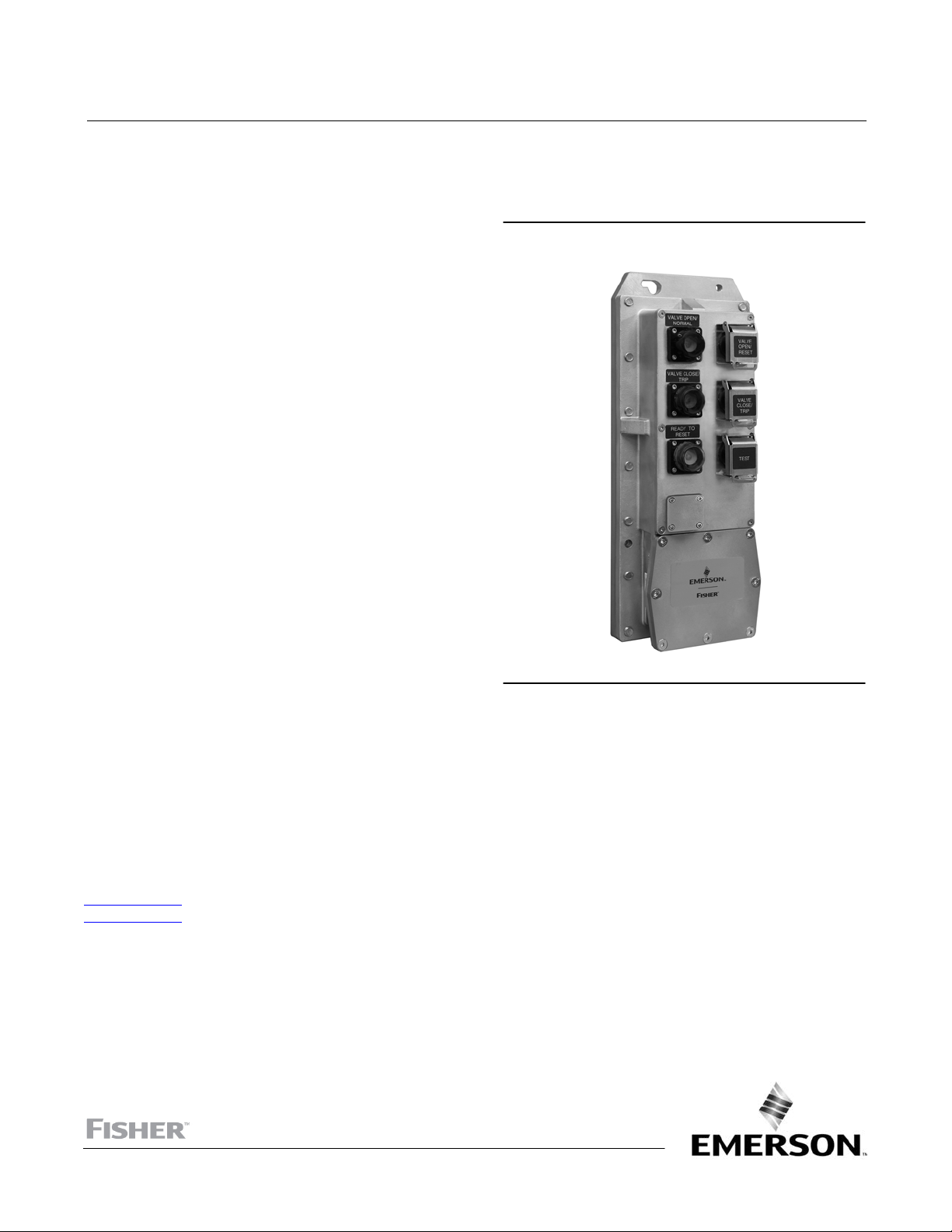
Figure 1. Fisher LCP200 Local Control Panel
X1536
Introduction
Scope of Manual
This instruction manual includes installation and maintenance information for the Fisher LCP200 local control panel
(figure 1). This device is used with Fisher FIELDVUE™ instruments in Safety Instrumented Systems (SIS). Refer to
instruction manual DVC6200 SIS Digital Valve Controllers for Safety Instrumented System (SIS) Solutions,
D103557X012
D103230X012
Unless otherwise noted, the information in this instruction manual applies to both DVC6200 SIS and DVC6000 SIS
digital valve controllers. For simplicity, the DVC6200 SIS model name will be used throughout.
www.Fisher.com
or DVC6000 SIS Digital Valve Controllers for Safety Instrumented System (SIS) Solutions,
for additional information.
Page 2

LCP200 Local Control Panel
August 2018
Do not install, operate, or maintain an LCP200 local control panel without being fully trained and qualified in valve,
actuator, and accessory installation, operation, and maintenance. To avoid personal injury or property damage, it is
important to carefully read, understand, and follow all of the contents of this manual, including all safety cautions and
warnings. If you have any questions about these instructions, contact your Emerson sales office
Instruction Manual
D104296X012
.
Description
The LCP200 local control panel is used with the HARTr communicating DVC6200 SIS digital valve controller. This panel
is used to manually open and close a safety shutdown valve. The LCP200 can be configured to auto or manual reset
after a trip. It also offers a smart auto reset configuration which requires a manual reset for locally initiated trips but
auto reset for all other trips. Additionally, it includes a button for initiating a partial stroke test.
Specifications
Typical specifications for the LCP200 local control panel are shown in table 1.
Educational Services
For information on available courses contact:
Emerson Automation Solutions
Educational Services - Registration
Phone: 1-641-754-3771 or 1-800-338-8158
e‐mail: education@emerson.com
emerson.com/fishervalvetraining
2
Page 3

Instruction Manual
D104296X012
Table 1. Specifications
LCP200 Local Control Panel
August 2018
Power Options
J External: 12VDC to 26.4VDC @ 50 mA maximum
continuous current (100 mA maximum inrush)
J Loop: 8-20 mA (LCP200 and DVC6200 SIS
combined)
Continuous Power Consumption
External: 1.4 W max
Loop (Point-to-Point): 48 mW
Loop (Multi-Drop): 120 mW
Temperature Limits
(1)
-40 to 65_C (-40 to 149_F)
Maximum distance between LCP200 and
DVC6200 SIS digital valve controller
Cable length is limited by maximum cable
capacitance of 340,000 pF
(2)
. Typical 1000 meters
(3280 feet) with 18 AWG shielded Audio, Control
and Instrumentation Cable
Contact Type and Ratings
Three single-pole double-throw (SPDT) relay switches
Each output is capable of 30 VDC with maximum
current of 200 mA at room temperature
Contact Operation
Reset: Activated for 1.5 to 3 seconds when Reset
button is pressed for 0.5 seconds or more
Trip: Activated for 1.5 to 3 seconds when Trip button
is pressed for 0.5 seconds or more
Test: Activated when partial stroke test is in progress
Electrical Classification
Pollution Degree IV, Overvoltage Category II per IEC
61010 clause 5.4.2d
Electromagnetic Interference (EMI)
Meets EN 61326-1:2013
Immunity—Industrial locations per Table 2 of
EN 61326-1 Standard. Performance is
shown in table 2 below.
Emissions—Class A
ISM equipment rating: Group 1, Class A
Connections
Two Conduit entries:
J 3/4 NPT or J M20
Wiring
14 to 26 AWG
Electrical Installation
Wire connections are polarity sensitive
Compatibility
DVC6200 SIS with Firmware revision 3 or later
DVC6000 SIS with Firmware revision 7 or later
Installation Orientation
Conduit entry locations must be facing down
Dimensions
406 mm long by 165 mm wide by 105 mm deep
See figure 2
Adapter is available for replacing the LCP100
Construction Materials
Housing material: 316SST
Approximate Weight
16.8 kg (37 lbs)
(3)(4)
Electrical Housing
IP66, Type 4X
Hazardous Area
FM (United States and Canada)—Intrinsically Safe for
Gas and Dust
ATEX—Intrinsically Safe for Gas and Dust
IECEx—Intrinsically Safe for Gas and Dust
Lights
Top (Green/Normal): Solid when the valve is at its
normal operating position, and loop current is normal
Middle (Red/Trip): Solid when the valve is at its trip
position and middle (Trip) loop current is tripped
Bottom (Yellow/Ready-to-Reset): Solid when the
valve is latched in the trip position, and loop current is
normal
-continued-
3
Page 4
LCP200 Local Control Panel
August 2018
Specifications (continued)
Instruction Manual
D104296X012
Pushbuttons
Protected with lockable covers
Top (Reset): After an emergency demand—
commands the valve to its normal position only after
loop current is restored (manual reset)
1. The pressure/temperature limits in this document and any other applicable code or standard should not be exceeded.
2. DVC6000 SIS: Cable length is limited by maximum cable capacitance of 240,000 pF, typically 765 meters (2510 feet).
3. DVC6200 SIS FW7 or later required for Auto detection of power source.
4. DVC6200 SIS FW7 or later is required for the test contact to change state.
Middle (Trip): Commands the valve to the configured
trip position
Bottom (Test): Commands the configured partial
stroke test. Can be overridden by the Trip button,
Reset button, or Emergency Demand
Table 2. Electromagnetic Immunity Performance for Fisher LCP200
Port Phenomenon Basic Standard Test Level
Electrostatic discharge (ESD) IEC 61000-4-2
Enclosure
I/O signal/
control/power
1. A = No degradation during testing. B = Temporary degradation during testing, but is self-recovering.
Radiated EM field IEC 61000-4-3
Radiated Power Magnetic IEC 61000-4-8 30 A/m A
Burst (fast transients) IEC 61000-4-4
Surge IEC 61000-4-5
Conducted RF IEC 61000-4-6 150 kHz to 80 MHz at 3 Vrms with 1 kHz AM at 80% A
$4 kV contact
$8 kV air
80 to 1000 MHz @ 10V/m with 1 kHz AM at 80%
1400 to 2000 MHz @ 3V/m with 1 kHz AM at 80%
2000 to 2700 MHz @ 1V/m with 1 kHz AM at 80%
$1 kV, I/O lines
$2 kV, DC power lines
$1 kV, I/O lines (line-to-ground)
$2 kV, DC power line (line-to-ground)
$1 kV, DC power line (line-to-line)
Performance
Criteria
A
A
A
B
(1)
4
Page 5
Instruction Manual
D104296X012
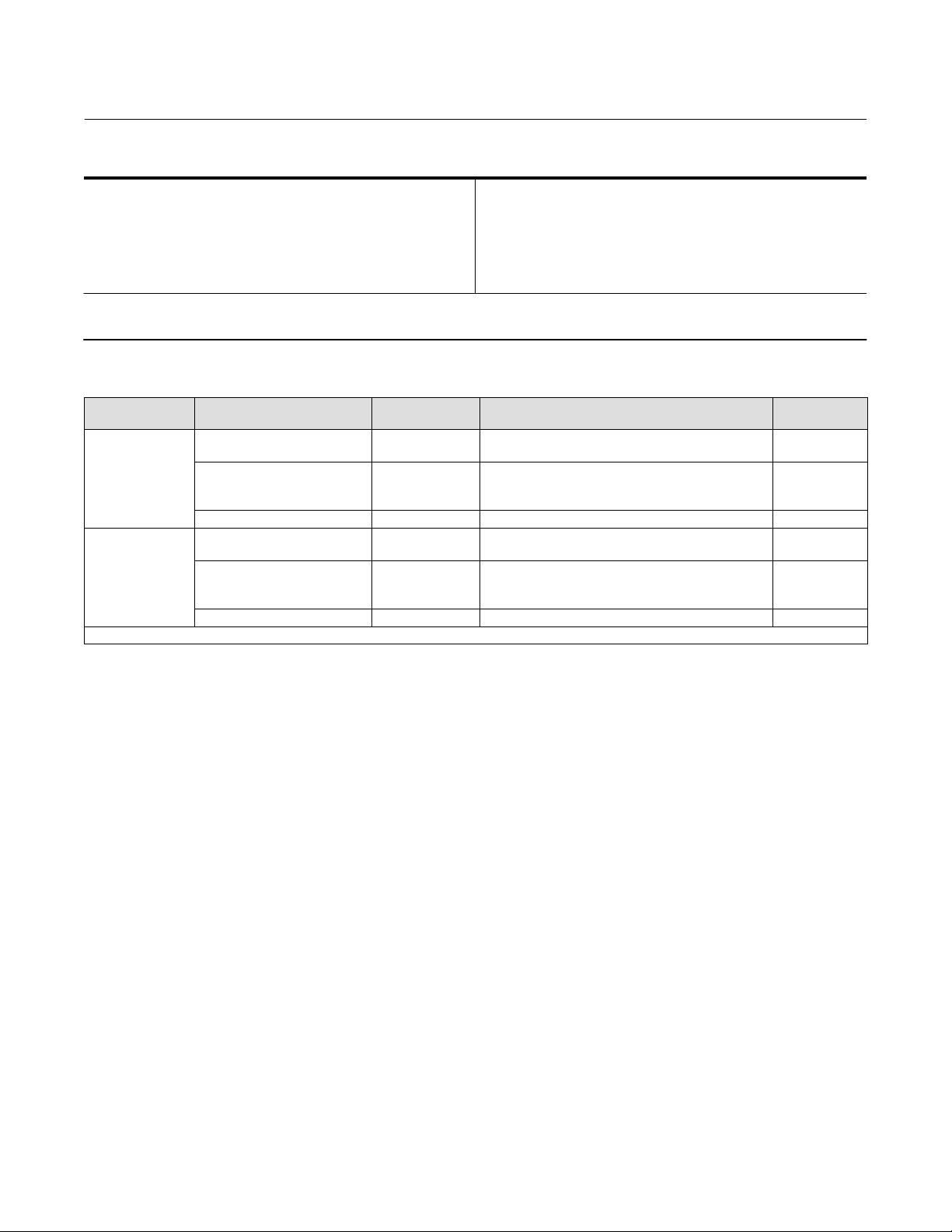
Figure 2. Fisher LCP200 Local Control Panel Dimensions
LCP200 Local Control Panel
August 2018
NOMINAL 8.5 mm
94
(3.7)
288
(11.3)
406
(16)
105
(4.1)
143
(5.6)
165
(6.5)
mm
(INCH)
5
Page 6

LCP200 Local Control Panel
August 2018
Instruction Manual
D104296X012
Installation
WARNING
The enclosure contains non-metallic enclosure parts. To prevent the risk of electrostatic sparking, the non-metallic surface
shall be cleaned with a damp cloth.
Note
Direct all wiring to the left side inside the LCP200 compartment, away from the buttons.
Hazardous Area Classifications and Special Instructions for “Safe Use” and
Installation in Hazardous Locations
Refer to the following instruction manual supplements for approval information.
D FM (United States and Canada) Hazardous Area Approvals - LCP200 Local Control Panel (D104369X012
D ATEX Hazardous Area Approvals - LCP200 Local Control Panel (D104370X012
D IECEx Hazardous Area Approvals - LCP200 Local Control Panel (D104371X012
All documents are available from your Emerson sales office
other approval/certification information.
or Fisher.com. Contact your Emerson sales office for all
)
)
)
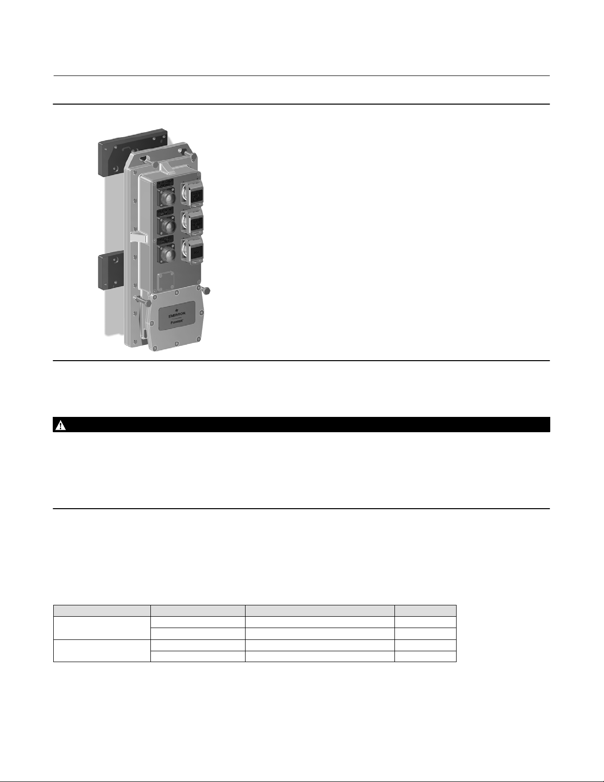
Mounting
Refer to figure 2 for dimensional information. The LCP200 local control panel has mounting holes for on‐site panel
mounting of the device.
Note
A mounting kit is available to use when replacing an LCP100 with the LCP200. Contact your Emerson sales office for information on
obtaining this kit. Refer to figure 3 for the LCP200 with the mounting bracket.
The LCP200 must be installed so that the wiring connections are on the bottom to prevent accumulation of moisture
inside the box.
6
Page 7
Instruction Manual
D104296X012
Figure 3. Fisher LCP200 with Mounting Bracket
LCP200 Local Control Panel
August 2018
Electrical Connections
WARNING
Select wiring and/or cable glands that are rated for the environment of use (such as hazardous location, ingress protection,
and temperature). Failure to use properly rated wiring and/or cable glands can result in personal injury or property damage
from fire or explosion.
Wiring connections must be in accordance with local, regional, and national codes for any given hazardous area approval.
Failure to follow the local, regional, and national codes could result in personal injury or property damage from fire or
explosion.
Refer to the appropriate wiring diagram, as defined in table 3, based on your installation requirements. Also refer to
figure 5 for LCP200 terminal connections, label details and information, as well as DVC6200 SIS terminal box details.
When connecting the wiring terminals tighten to a torque of 0.8 N•m (7 lbf•in) +/- 10%, using a 3 mm thin blade, flat
head screwdriver.
Table 3. Wiring Configurations with DVC6200 SIS Digital Valve Controller
LCP200 Power Source System Output DVC6200 SIS Mode (Current or Voltage) Refer to figure
LOOP
24 VDC External Power
8-20 mA Point-to-Point 6
24 VDC Multi-Drop 8
4-20 mA Point-to-Point 7
24 VDC Multi-Drop 9
7
Page 8

LCP200 Local Control Panel
August 2018
Instruction Manual
D104296X012
Note
For intrinsically safe applications, the LCP200 forms an intrinsically safe explosion protection system when used with intrinsically
safe associated apparatus (a barrier) or with any other intrinsically safe devices.
The following requirements must be met: Uo ≤ Ui , Io ≤ Ii, Po ≤ Pi , Co ≥ Ci + Cc, Lo ≥ Li + Lc.
When installing the terminal cover, use a 4 mm hex key to tighten the screws evenly in a criss‐cross pattern, such as
the one indicated in figure 4, to a torque of 8.7 N•m (77 lbf•in) +/- 10%, to help ensure the cover is properly installed.
Apply silicone lubricant to the terminal box O-ring (key 7, figure 10).
Figure 4. Proper Cover Installation
1
7
3
NOTE: TIGHTEN THE SCREWS IN A CRISS‐CROSS PATTERN
TO HELP ENSURE PROPER COVER INSTALLATION.
X1536
8
5
6
4
8
2
Page 9

Instruction Manual
D104296X012
Figure 5. Interior Details of Fisher LCP200 and FIELDVUE DVC6200 SIS
LCP200 Local Control Panel
August 2018
AUX +
AUX -
24VDC +
24VDC -
GG54648-Sheet 5
LOOP -
LOOP +
TEST
AUX LOOP
24V
POWER
DVC6200 SIS
LCP200 INTERIOR
TRIP
TEST
RESET
TRIP
NOT
AVAILABLE
ELECTRICAL ENTRY
3/4 NPT OR M20
EARTH GROUND
SAFETY GROUND
AUX +
AUX -
RESET
EARTH GROUND
TALK TALK +
LOOP LOOP +
SAFETY
GROUND
DVC6200 SIS
TERMINAL BOX INTERIOR
9
Page 10

LCP200 Local Control Panel
August 2018
Figure 6. Wiring Diagram 1, HART LOOP-Powered Configuration, Point-to-Point
DVC6200 SIS
LCP200
TERMINAL BOX
Instruction Manual
D104296X012
24V
POWER
AUX LOOP
DVC6200 SIS
TEST TRIP
RESET
NOT
AVAILABLE
TALK
AUX LOOP
OUT
CAL
2
3
NOTES:
1 OPTIONAL CABLING TO RESET, TRIP, AND TEST CONTACTS. SHOWN ABOVE IS CABLING TO
1 RESET CONTACT.
2 CONNECT EITHER NO-C OR NC-C TERMINALS OF RESET, TRIP AND TEST CONTACTS. SHOWN
1 ABOVE IS RESET NO-C TERMINALS.
3 USE METAL CONDUIT FOR CABLING BETWEEN DVC6200 SIS AND LCP200 AS EMI SHIELD.
4 THE DIGITAL INPUT DOES NOT NEED TO BE CONNECTED FOR THE LCP200 TO OPERATE.
LOGIC SOLVER
(USER SUPPLIED)
1
DIGITAL IN
ANALOG OUT
(8-20 mA)
4
GG22618 SHEET 2
10
Page 11

Instruction Manual
D104296X012
Figure 7. Wiring Diagram 2, 24 VDC External Power Configuration, Point-to-Point
LCP200 Local Control Panel
August 2018
1
DIGITAL IN
4
DVC6200 SIS
TERMINAL BOX
TALK
AUX LOOP
OUT
CAL
24V
POWER
LCP200
AUX LOOP
DVC6200 SIS
TEST TRIP
RESET
NOT
AVAILABLE
2
3
NOTES:
1 OPTIONAL CABLING TO RESET, TRIP, AND TEST CONTACTS. SHOWN ABOVE IS CABLING TO
1 RESET CONTACT.
2 CONNECT EITHER NO-C OR NC-C TERMINALS OF RESET, TRIP AND TEST CONTACTS. SHOWN
1 ABOVE IS RESET NO-C TERMINALS.
3 USE METAL CONDUIT FOR CABLING BETWEEN DVC6200 SIS AND LCP200 AS EMI SHIELD.
4 THE DIGITAL INPUT DOES NOT NEED TO BE CONNECTED FOR THE LCP200 TO OPERATE.
OUTPUT
4-20 mA
LOGIC SOLVER
(USER SUPPLIED)
24 VDC
SOURCE
(USER SUPPLIED)
GG22618 SHEET 4
11
Page 12

LCP200 Local Control Panel
August 2018
Figure 8. Wiring Diagram 3, HART LOOP-Powered Configuration, Multi-Drop
Instruction Manual
D104296X012
LCP200
TEST TRIP
AUX LOOP
24V
DVC6200 SIS
POWER
NOTES:
1 OPTIONAL CABLING TO RESET, TRIP AND TEST CONTACTS. SHOWN ABOVE IS CABLING TO
1 RESET CONTACT.
2 CONNECT EITHER NO-C OR NC-C TERMINALS OF RESET, TRIP AND TEST CONTACTS. SHOWN
1 ABOVE IS RESET NO-C TERMINALS.
3 USE METAL CONDUIT FOR CABLING BETWEEN DVC6200 SIS AND LCP200 AS EMI SHIELD.
4 THE DIGITAL INPUT DOES NOT NEED TO BE CONNECTED FOR THE LCP200 TO OPERATE.
GG22618 SHEET 3
RESET
NOT
AVAILABLE
2
3
TERMINAL BOX
TALK
AUX LOOP
OUT
CAL
DVC6200 SIS
1
FLD
SYS
LC340 LINE
CONDITIONER
LOGIC SOLVER
(USER SUPPLIED)
DIGITAL IN
4
OUTPUT
24 VDC
12
Page 13

Instruction Manual
D104296X012
Figure 9. Wiring Diagram 4, 24 VDC External Power Configuration, Multi-Drop
LCP200 Local Control Panel
August 2018
1
DIGITAL IN
4
DVC6200 SIS
TERMINAL BOX
TALK
AUX LOOP
OUT
CAL
24V
POWER
AUX LOOP
DVC6200 SIS
LCP200
TEST TRIP
RESET
NOT
AVAILABLE
2
3
NOTES:
1 OPTIONAL CABLING TO RESET, TRIP AND TEST CONTACTS. SHOWN ABOVE IS CABLING TO
1 RESET CONTACT.
2 CONNECT EITHER NO-C OR NC-C TERMINALS OF RESET, TRIP AND TEST CONTACTS. SHOWN
1 ABOVE IS RESET NO-C TERMINALS.
3 USE METAL CONDUIT FOR CABLING BETWEEN DVC6200 SIS AND LCP200 AS EMI SHIELD.
4 THE DIGITAL INPUT DOES NOT NEED TO BE CONNECTED FOR THE LCP200 TO OPERATE.
GG22618 SHEET 5
FLD
SYS
LC340 LINE
CONDITIONER
OPUTPUT
24 VDC
LOGIC SOLVER
(USER SUPPLIED)
24 VDC
SOURCE
(USER SUPPLIED)
13
Page 14

LCP200 Local Control Panel
August 2018
Instruction Manual
D104296X012
Setup
In order for the LCP200 to operate properly, it must be connected to a DVC6200 SIS with firmware revision 3 or later,
or a DVC6000 SIS device with firmware revision 7 or later. Once the physical connections are made, use the following
checklist to configure the LCP200. Refer to the DVC6200 SIS instruction manual (D103557X012
instruction manual (D103230X012
) if additional setup information is needed.
D Using a 475 Field Communicator select Configure > Guided Setup > Device Setup. Follow the prompts on the Field
Communicator:
Enter Supply Pressure and Unit
Enter Actuator Make, Model, and Size
Enter Partial Stroke test Starting Point, Relay Type and Zero Power Condition [select the “instrument connected to
local control panel (LCP200)” option]
D Use Device Setup to configure the digital valve controller with the LCP200.
D Continue to set up the digital valve controller according the normal set up procedure.
D Remember to place the instrument back in service before disconnecting.
) or the DVC6000 SIS
Note
An alternative method to configure the LCP200 is through Manual Setup. Using the Field Communicator, select Configure >
Manual Setup > Instrument > Terminal Box > Edit Auxiliary Terminal Action > SIS Local Control Panel. When this setting is downloaded
to the device, an information screen will pop up advising that some additional parameters will be configured. Select Yes.
14
Page 15

Instruction Manual
D104296X012
LCP200 Local Control Panel
August 2018
Principle of Operation
The lights indicate the state of the valve as described in table 4. Contact operation is described in table 5.
Note
The primary safety function should be implemented by controlling the current (in point‐to‐point mode) or voltage (in multi‐drop
mode) from the logic solver. The Middle (Red/Trip) button is not intended to perform the primary safety function for the process.
Table 4. Fisher LCP200 Light and Button Operation
WHAT THE LCP200 LIGHTS SHOW... POSSIBLE CONDITIONS...
Solid The valve is in its normal operating state. - - - Trip Run PST
The valve is in the process of running a partial stroke
test (PST).
Top
(Green/Normal)
Middle
(Red/Trip)
Bottom
(Yellow/
Ready-to-Reset)
Notes:
1. If the top, middle, and bottom lights are blinking in sequence, then the DVC6200 SIS is out of service. In point-to-point mode, the DVC6200 SIS will not
respond to a trip from the logic solver.
2. Depending on the emergency shutdown valve configuration, the top button could be labeled “Valve Open” and the middle button could be labeled
“Valve Close”; or vice versa. The bottom button will aways be labeled “Valve Test”.
3. Acknowledgment of a PST failure means that the LCP200 will return the blinking top light to a solid light. The PST alert will still be visible via HART
communication with the DVC6200 SIS.
4. If the top and middle lights are both solid the valve is throttling in mid‐travel.
5. The information contained in this table applies to firmware 9 and later.
Fast Blink (1/2 second)
Slow Blink (1 second) A partial stroke test has failed.
Solid
Fast Blink (1/2 second)
Solid The valve may be reset to the normal operating state.
The valve is not at its normal operating position because
the actuator pressure is low or the valve is stuck.
The valve is tripped but is stuck at the normal position. - - - - - - - - -
The valve is tripped due to loss of actuator pressure
(e.g., solenoid valve trip)
The valve is tripped due to a command from the logic
solver or LCP200.
The valve is stuck in the tripped state. - - - - - - - - The valve is at mid-travel after a trip. The valve may be
moving or stuck in this position.
PRESS INDICATED BUTTON TO...
Top Middle Bottom
Stop PST Trip Stop PST
Acknowledge
PST Failure
Acknowledge
PST Failure
Acknowledge
PST Failure
- - - - - - - - -
- - - - - - - - -
Reset to
Normal State
Trip Run PST
Trip Run PST
Trip Run PST
- - - - - -
Table 5. Fisher LCP200 Contact Operation
Contact Normal Operation Bench Mode
Trip
Reset
Test Activated when partial stroke test is in progress. Activated as long as Test button is pressed.
1. Refer to the Maintenance section for Bench Mode details.
Activated for 1.5 to 3 seconds when Trip button is
pressed for 0.5 seconds or more.
Activated for 1.5 to 3 seconds when Reset button is
pressed for 0.5 seconds or more.
Activated as long as Trip button is pressed.
Activated as long as Reset button is pressed.
15
Page 16

LCP200 Local Control Panel
August 2018
Instruction Manual
D104296X012
Operation Verification
Before connecting the LCP200 to the process, conduct the following tests on the LCP200 connected to the
DVC6200 SIS.
Successful Partial Stroke Test
1. Verify that the Top (Green/Normal) light is on solid.
2. Press the Bottom (Test) pushbutton for more than 3 seconds (but less than 10 seconds).
3. Observe that the top light starts flashing when the valve starts moving.
4. Observe that the valve moves no more than the configured partial stroke test travel limit.
5. Observe that the valve returns to the normal operating position and the top light comes on solid.
6. If the relay contacts are being used, verify that the Test contact changes state when the PST is in progress. When
the PST is complete verify that the contact returns to the pre-PST state.
Manually Aborted Partial Stroke Test
1. Verify that the Top (Green/Normal) light is on solid.
2. Press the Bottom (Test) pushbutton for more than 3 seconds (but less than 10 seconds).
3. Observe that the top light starts flashing when the valve starts moving.
4. Before the valve reaches the travel limit of the configured partial stroke test, press the Top (Reset) pushbutton or
the bottom pushbutton.
5. Observe that the valve immediately returns to the normal operating position and the top light comes on solid and if
the contact is being used, the Reset contact changes state for 1.5 to 3 seconds.
6. If the relay contacts are being used, verify that the Test contact changes state when the PST is in progress.
Emergency Demand through the Logic Solver
1. Reduce the current to the DVC6200 SIS to 4 mA (for de‐energize to trip operation).
Note
For a loop powered installation, a minimum current of 8 mA is required at the trip state / “Safety Demand” for proper functioning
of the pushbuttons and lights.
2. Observe that the valve moves to its Trip state.
3. Observe that the Middle (Red/Trip) light comes on solid and the Bottom (Yellow/Ready-to-Reset) light stays off.
4. Increase the current to the DVC6200 SIS to 20 mA (for de‐energize to trip) and observe that the valve behaves as
configured in the reset option i.e., Auto, Manual, or Smart Auto. If the configuration is for auto reset, skip steps 5
and 6.
5. Observe that the middle light stays on solid and the bottom light comes on solid (ready to reset).
6. Press the Top (Reset) pushbutton.
7. Observe that the middle and bottom lights go off, the valve moves to its normal operating position, and then the
Top (Green/Normal) light comes on solid.
8. If the relay contacts are being used, verify that the Reset contact changes state for 1.5 to 3 seconds when the top
pushbutton is pressed.
16
Page 17

Instruction Manual
D104296X012
Emergency Demand and Reset through Local Control Panel
1. Press the Middle (Trip) pushbutton.
2. Observe that the valve moves to it Trip position.
3. Observe that the Middle (Red/Trip) light comes on solid and the Bottom (Yellow/Ready-to-Reset) light is on solid.
4. If the relay contacts are being used, verify that the Trip contact changes state for 1.5 to 3 seconds when the middle
pushbutton is pressed.
5. Press the Top (Reset) pushbutton.
6. Observe that the middle light goes off, the valve moves to its normal operating position, and then the Top
(Green/Normal) light comes on solid.
7. If the relay contacts are being used, verify that the Reset contact changes state for 1.5 to 3 seconds when the top
pushbutton is pressed.
LCP200 Local Control Panel
August 2018
Maintenance
The LCP200 has six major components; the housing, lights, buttons, conduit connections, electronics, and contacts. If
a light is not working it can be replaced as a module. If any of the buttons are not working then the front panel needs
to be replaced. The conduit connections do not normally need replacement. The electronics module, which includes
the relay contacts, can be replaced as an assembly.
The LCP200 enters a bench mode when it is powered and not connected to a digital valve controller, i.e. the auxiliary
terminals are not connected to the DVC6200 SIS. In this mode, the light next to each button will be on solid when the
button is pressed. The corresponding relay contact will change state as long as the respective button is pressed. This
can be used to identify stuck buttons, faulty lights, or relay contacts.
Note
Parts kits for the following maintenance procedures are available on page 20 and 20.
Refer to figure 10 and 11 for key number locations.
Replacing the LED Assembly
The LED's can be replaced in the field without removing power.
CAUTION
Ensure the LED enclosure does not get contaminated with dust, moisture, or other contaminants during this procedure.
Exposure to dust, moisture, or other contaminants can damage the electronics.
1. Unscrew the four socket cap screws (key 45) holding the LED module (key 32) in place using a 2.5 mm hex key and
remove the LED module and the LED base O-ring (key 46). Also remove the four O-rings (key 47).
2. Replace with new O-rings and LED module. Apply silicone lubricant to the O-rings.
3. Replace the required lens cap on the LED module. Install the 4 socket cap screws and tighten to a torque of
0.77 N•m (6.8 lbf•in) +/- 10% .
17
Page 18

LCP200 Local Control Panel
August 2018
Instruction Manual
D104296X012
Replacing the LED Assembly with an LED Light Cover
The LED's can be replaced in the field without removing power.
CAUTION
Ensure the LED enclosure does not get contaminated with dust, moisture, or other contaminants during this procedure.
Exposure to dust, moisture, or other contaminants can damage the electronics.
Note
Install the the LED Blanking kit on a flat surface to ensure that the socket cap screws (key 45) can be securely installed.
1. Unscrew the four socket cap screws (key 45) holding the LED module (key 32) in place using a 2.5 mm hex key and
remove the LED module and the LED base O-ring (key 46). Also remove the four O-rings (key 47). The LED module
and O-rings can be retained for later use if required.
2. Install the new LED base O-ring (key 46) and LED light cover (key 33). Apply silicone lubricant to the O-ring.
3. Install the four socket cap screws and tighten to a torque of 0.77 N•m (6.8 lbf•in) +/- 10%.
Replacing the Front Panel Assembly
WARNING
Disconnect power and remove the LCP200 from service before replacing the front panel assembly. Person injury or
property damage may result if power is not disconnected.
CAUTION
Ensure the front panel assembly is not exposed to dust, moisture, or other contaminants during this procedure. Exposure
to dust, moisture, or other contaminants can damage the electronics.
1. Disconnect the LCP200 from the digital valve controller and remove power to the LCP200. Move to a safe
environment, such as a maintenance shop or service area.
2. Unscrew the six flat head socket screws (key 14) holding the front panel assembly cover in place using a 2.5 mm hex
key and remove the cover.
3. Remove front panel assembly, including panel O-ring (key 44).
4. Replace with new panel O-ring and front panel assembly. Apply silicone lubricant to the O-ring.
5. Install the six flat head socket screws and tighten to a torque of 2.2 N•m (19.5 lbf•in) +/- 10%.
Before reconnecting to the digital valve controller and placing in service, put the LCP200 into bench mode and verify
the light next to each button is on solid when the button is pressed and the corresponding relay contact changes state
for as long as the button is pressed.
18
Page 19

Instruction Manual
LCP200 Local Control Panel
D104296X012
Instrument Troubleshooting
If difficulties are experienced with the LCP200 control panel, refer to table 6.
Table 6. Instrument Troubleshooting
Symptom Possible Cause Action
1. Lights are not lit. 1. LCP200 is not properly connected to the
2. LCP200 is properly connected to
the digital valve controller aux.
terminal, but the lights are not lit.
3. The power wires are landed
correctly but the lights are not lit.
4. The LCP200 and the digital valve
controller are properly connected,
and there is sufficient current but
the lights are not lit.
5. Lights are blinking. 5. Valve is not at it's normal stop. 5. Check for proper calibration. Re‐run calibration if necessary.
6. Proper calibration but lights are
blinking.
7. Button is pressed but expected
action does not occur.
digital valve controller aux. terminal.
2. Power is not connected to the correct
terminals.
3. Loop Power option is selected, but there
is not enough current.
4. The LED may be damaged. 4. Replace LED. If possible take the LCP200 to bench mode and verify
6. Hi Hi / Lo Lo alerts settings not correctly
set.
7.Time requirements may not be met. 7. Ensure time requirements for the button press is met. If the problem
1. Ensure that the LCP200 is connected correctly to the digital valve
controller aux. terminal, as described in the Installation section of this
manual.
2. Ensure that the loop/24V power is landed at the appropriate
terminals.
3. The Loop Power Option requires 8 mA current to operate. Ensure
that there is sufficient current.
that the LED does not light up when the corresponding button is
pressed.
6. Ensure that the Hi Hi / Lo Lo Alert settings are 99 and 1% respectively.
For large rotary valve, adjust settings to 98 and 2% and observe.
persists take the LCP200 into bench mode and press the the respective
button and verify that the relay contact changes state when the button
is pressed. Verify that the corresponding light is on solid.
August 2018
19
Page 20

LCP200 Local Control Panel
August 2018
Instruction Manual
D104296X012
Parts Ordering
When corresponding with your Emerson sales office about this equipment, mention the serial number found on the
nameplate of the unit.
WARNING
Use only genuine Fisher replacement parts. Components that are not supplied by Emerson Automation Solutions should
not, under any circumstances, be used in any Fisher instrument. Use of components not supplied by Emerson may void
your warranty and hazardous area approval, might adversely affect the performance of the instrument, and could cause
personal injury and property damage.
Parts Kits
Kit Description Part Number
1 LED Assemblies Kit (see figure 11) GG54645X012
Includes LED module, qty. 1 (key 32); Lens cap, qty. 3,
green, red, yellow (key 34, 35, 36); LED base O-ring, qty. 2
(key 46); Socket cap screw, qty. 4 (key 45); O-ring, qty. 4
(key 47)
Note
The LED Assemblies Kit replaces one LED.
2 LED Blanking Kit (see figure 11) GG54849X012
Includes LED base O-ring, qty. 3 (key 46); Socket
cap screw, qty. 12 (key 45); LED light cover, qty. 3, (key 33)
3 Soft Parts Kit (see figure 10) GG54647X012
Includes LED base O-ring, qty. 8 (key 46); Terminal O-ring, qty. 1
(key 7); Panel O-ring, qty. 1 (key 44)
Kit Description Part Number
4 Front Panel Assembly Kits (see figure 11)
Note
The Front Panel Assembly Kits contain LEDs and included buttons
pre-assembled on the front panel assembly (key 30). It also includes the
panel O-ring (key 44).
All Buttons included GG54649X012
Includes Flat head socket screw, qty. 6 (key 14); Front panel
assembly, qty. 1 (key 30); Pushbutton O-ring, qty. 3 (key 40);
Pushbutton, qty. 3 (key 38); Shroud, qty. 3 (key 39)
Reset & Trip Buttons included GG54650X012
Reset & Test Buttons included GG54651X012
Test & Trip Buttons included GG54652X012
Kits include Flat head socket screw, qty. 6 (key 14); Front panel
assembly, qty. 1(key 30); Pushbutton O-ring, qty. 3 (key 40);
Pushbutton, qty. 2 (key 38); Shroud, qty. 2 (Key 39); Blank
pushbutton, qty. 1 (key 12, 304, 305)
Reset Button included GG54653X012
Trip Button included GG54654X012
Test Button included GG54655X012
20
Kits include Flat head socket screw, qty. 6 (key 14); Front panel
assembly, qty. 1 (key 30); Pushbutton O-ring, qty 3 (key 40);
Pushbutton, qty. 1 (key 38); Shroud, qty. 1 (key 39); Blank
pushbutton, qty. 2 (key 12, 304, 305)
Page 21

Instruction Manual
D104296X012
Figure 10. Fisher LCP200 Assembly
32
28
46
28
44
34 GREEN
35 RED
36 YELLOW
38
39
28
LCP200 Local Control Panel
August 2018
14
16
7
4
12
APPLY LUBRICANT/SEALANT/TORQUE SEAL
GG54648-2
21
Page 22

LCP200 Local Control Panel
August 2018
Figure 11. Front Panel Assembly
GREEN 34
RED 35
YELLOW 36
16
30
28
28
45
44
32
46
47
33
39
38
Instruction Manual
D104296X012
304
28
40
APPLY LUBRICANT/SEALANT/TORQUE SEAL
GG54648
16
14
12
305
16
22
Page 23

Instruction Manual
D104296X012
LCP200 Local Control Panel
August 2018
23
Page 24

LCP200 Local Control Panel
August 2018
Instruction Manual
D104296X012
Neither Emerson, Emerson Automation Solutions, nor any of their affiliated entities assumes responsibility for the selection, use or maintenance
of any product. Responsibility for proper selection, use, and maintenance of any product remains solely with the purchaser and end user.
Fisher and FIELDVUE are marks owned by one of the companies in the Emerson Automation Solutions business unit of Emerson Electric Co. Emerson
Automation Solutions, Emerson, and the Emerson logo are trademarks and service marks of Emerson Electric Co. HART is a registered trademark of
FieldComm Group. All other marks are the property of their respective owners.
The contents of this publication are presented for informational purposes only, and while every effort has been made to ensure their accuracy, they are not
to be construed as warranties or guarantees, express or implied, regarding the products or services described herein or their use or applicability. All sales are
governed by our terms and conditions, which are available upon request. We reserve the right to modify or improve the designs or specifications of such
products at any time without notice.
Emerson Automation Solutions
Marshalltown, Iowa 50158 USA
Sorocaba, 18087 Brazil
Cernay, 68700 France
Dubai, United Arab Emirates
Singapore 128461 Singapore
www.Fisher.com
24
E 2018 Fisher Controls International LLC. All rights reserved.
 Loading...