

Page 1
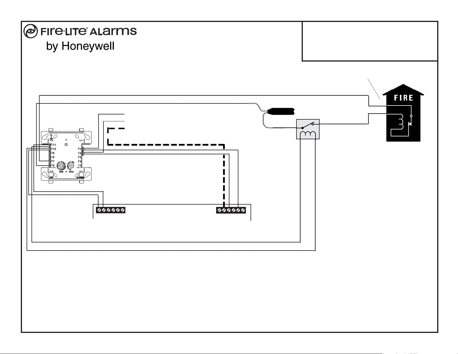
MBT-1 Municipal Box Trip
for Fire-Lite Fire Alarm Control Panels
One Fire-Lite Place, Northford, CT 06472
The CMF-300 must be programmed as
'Silenceable' and 'General Alarm.'
Alarm polarity shown!
+ -
+
+
CMF-300*
+ -
- To next device
+ on SLC Loop
Braided-shield/Drain Wire
24VDC, Nonresettable
TB4
MS-9200
Shield
B
White Wire
Brown Wire
Power Supervision Relay
+ -
EOLR-1
B SLC LOOP
TB6
Document 52033 Rev C 02/19/08 ECN 08-116
MBT-1
Red Black
(Contacts shown in
energized position)
Connect wires to two
red terminals on box
Gamewell Model M34-56
Local Energy Municipal Box
Note: 10 ohms maximum loop resistance due to wiring from power
supply to Municipal Box.
* If the SLC device does not match the one in this figure, refer
to the SLC Manual (document #51309) wiring conversion
charts for legacy and newer versions of the modules.
NFPA 72 Auxiliary Protective Signaling System
For connection of initiating devices and modules in this system, refer to the MS-9200 Installation Manual, Document 51003.
This application is not suitable for separate transmission of sprinkler supervisory or trouble conditions.
1 of 5
MS-9200
(Alarm Signal Transmission)
Document 52033 Rev. C 02/19/08
Page 2
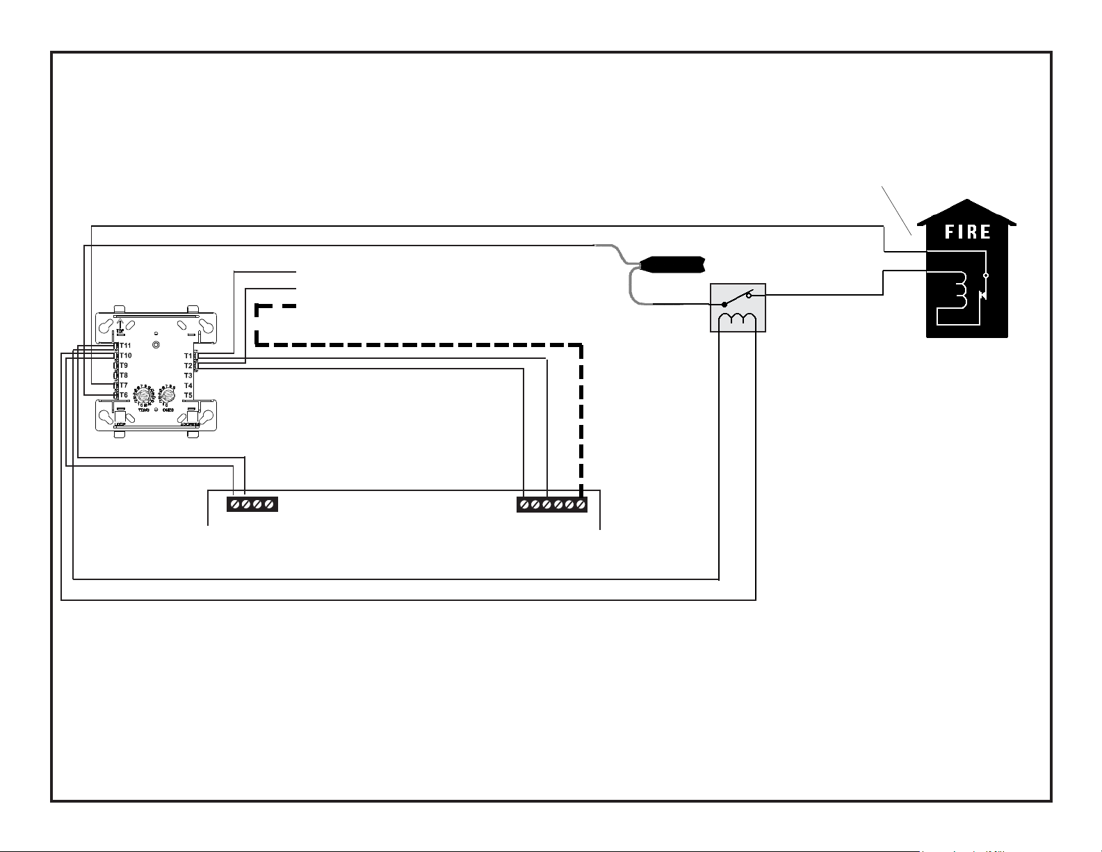
The CMF-300 must be programmed as
'Silenceable' and 'General Alarm.'
Alarm polarity shown!
+ -
+
+
CMF-300*
- To next device
+ on SLC Loop
Braided-shield/Drain Wire
White Wire
Brown Wire
EOLR-1
Power Supervision Relay
Red Black
MBT-1
Connect wires to two
red terminals on box
(Contacts shown in
energized position)
Gamewell Model M34-56
Local Energy Municipal Box
Note: 10 ohms maximum loop resistance due to wiring from power
supply to Municipal Box.
+ -
24VDC, Nonresettable
TB1
* If the SLC device does not match the one in this figure, refer
to the SLC Manual (document #51309) wiring conversion
charts for legacy and newer versions of the modules.
MS-9200UD
NFPA 72 Auxiliary Protective Signaling System
For connection of initiating devices and modules in this system, refer to the MS-9200UD Installation Manual, Document 51906.
This application is not suitable for separate transmission of sprinkler supervisory or trouble conditions.
SLC LOOP B
+ -
B
Shield
TB10
MS-9200UD & MS-9200UDLS
(Alarm Signal Transmission)
Document 52033 Rev. C 02/19/08
2 of 5
Page 3

The CMF-300 must be programmed as
'Silenceable' and 'General Alarm.'
Alarm polarity shown!
+ -
+
+
CMF-300*
- To next device
+ on SLC Loop
Braided-shield/Drain Wire
White Wire
Brown Wire
EOLR-1
Power Supervision Relay
Red Black
MBT-1
Connect wires to two
red terminals on box
(Contacts shown in
energized position)
Gamewell Model M34-56
Local Energy Municipal Box
Note: 10 ohms maximum loop resistance due to wiring from power
supply to Municipal Box.
24VDC, Nonresettable
+ -
TB3
* If the SLC device does not match the one in
this figure, refer to the SLC Manual (document #51309) wiring conversion charts for
legacy and newer versions of the modules.
For connection of initiating devices and modules in this system, refer to the MS-9600 Installation Manual, Document 51335.
This application is not suitable for separate transmission of sprinkler supervisory or trouble conditions.
IMPORTANT! This application, utilizing an MBT-1 and an MS-9600 FACP, is only possible when the MS-9600 has
Software Version 1.2 or Greater installed.
Note: MS-9600LS and MS-9600UDLS Fire Alarm Control Panels are FM Approved.
SLC LOOP B
MS-9600
+ -
TB8
B
Shield
MS-9600, MS-9600LS & MS-9600UDLS
(Software Version 1.2 or Greater)
NFPA 72 Auxiliary Protective Signaling System
(Alarm Signal Transmission)
3 of 5
Document 52033 Rev. C 02/19/08
Page 4

The CMF-300 must be programmed as
'Silenceable' and 'General Alarm.'
Alarm polarity shown!
+ -
+
+
CMF-300*
SLC LOOP
- To next device
+ on SLC Loop
Braided-shield/Drain Wire
B + - B
Shield
- +
White Wire
Brown Wire
EOLR-1
Power Supervision Relay
ANN-BUS Power,
Nonresettable
MBT-1
Red Black
(Contacts shown in
energized position)
Connect wires to two
red terminals on box
Gamewell Model M34-56
Local Energy Municipal Box
Note: 10 ohms maximum loop resistance due to wiring from power
supply to Municipal Box.
TB2
* If the SLC device does not match the one in this figure, refer
to the SLC Manual (document #51309) wiring conversion
charts for legacy and newer versions of the modules.
NFPA 72 Auxiliary Protective Signaling System
For connection of initiating devices and modules in this system, refer to the MS-9050UD Installation Manual, Document 52413.
This application is not suitable for separate transmission of sprinkler supervisory or trouble conditions.
MS-9050UD
Using ANN-BUS Power
(Alarm Signal Transmission)
TB3
MS-9050UD
Document 52033 Rev. C 02/19/08
4 of 5
Page 5

The CMF-300 must be programmed as
'Silenceable' and 'General Alarm.'
Alarm polarity shown!
+ -
+
+
CMF-300*
+ -
- To next device
+ on SLC Loop
Braided-shield/Drain Wire
SLC
LOOP
+ -
B
B
NAC Power*
Shield
White Wire
Brown Wire
EOLR-1
Power Supervision Relay
Red Black
MBT-1
Connect wires to two
red terminals on box
(Contacts shown in
energized position)
Gamewell Model M34-56
Local Energy Municipal Box
Note: 10 ohms maximum loop resistance due to wiring from power
supply to Municipal Box.
TB1
*NAC 1 must be programmed
as a Non-Resettable Power type
* If the SLC device does not match the one in this figure, refer
to the SLC Manual (document #51309) wiring conversion
charts for legacy and newer versions of the modules.
NFPA 72 Auxiliary Protective Signaling System
For connection of initiating devices and modules in this system, refer to the MS-9050UD Installation Manual, Document 52413.
This application is not suitable for separate transmission of sprinkler supervisory or trouble conditions.
5 of 5
TB2
MS-9050UD
MS-9050UD
Using NAC Power*
(Alarm Signal Transmission)
Document 52033 Rev. C 02/19/08
 Loading...