

Page 1
INSTALLATION INSTRUCTIONS FOR M302(A)
TWO-WIRE CONVENTIONAL DETECTOR MONITOR MODULE
This information is included with the modules as a quick reference installation guide. Refer to the appropriate Fire-Lite product
manual for detailed system information. If the modules will be installed in an existing operational system, inform the operator
and local authority that the system will be temporarily out of service. Disconnect power to the control panel before installing the
modules.
GENERAL DESCRIPTION
The M302(A) monitor module allows addressable panels to interface and monitor two-wire conventional smoke detectors. All two-wire detectors being monitored must be UL compatible with the module.
The module is addressed through the communication line (SLC) of addressable systems. When the module is interrogated, it transmits the status of one
zone of two-wire detectors to an addressable control panel. Status conditions
are reported as NORMAL, OPEN, or ALARM. The monitor module supervises
the zone of detectors and the connection of a power source.
4
4
5
3
3
6
27
27
8
1
1
9
0
0
5
6
8
9
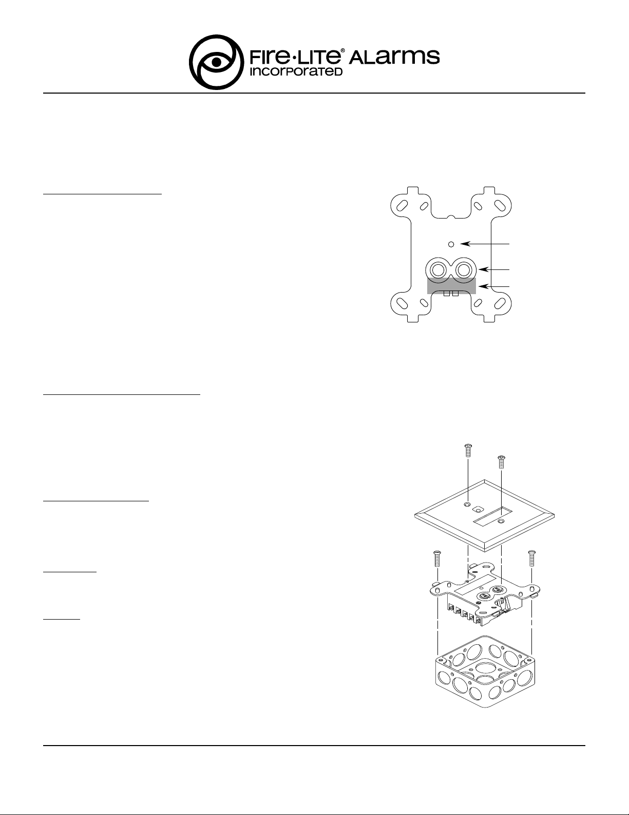
STATUS LED
ROTARY DECADE
ADDRESS SWITCHES
MAGNET TEST
POSITION
Two rotary decade switches allow setting module addresses from 00–99. A
status LED indicator is provided and is controlled by code command from the
control panel. The module provides a magnetically activated test switch for
testing the module’s electronics and connections to the control panel (see Fig-
MODULE CONTROLS AND INDICATORS
FIGURE 1.
ure 1).
COMPATIBILITY REQUIREMENTS
To insure proper operation, this module shall be connected to compatible Fire-Lite addressable control panels only.
Conventional two-wire smoke detectors must be UL compatible with the UL
listed monitor module. For the ULC listed monitor module, the conventional 2wire smoke detectors must be ULC compatible with the monitor module. A list
of compatible two-wire conventional detectors is available from Fire-Lite (P/N
15384).
PACKAGE CONTENTS
(1) Two-wire monitor module, P/N M302
(1) 3.9K ohm end-of-line resistor (A2143-10)
(1) Off-white cover plate
(1) Screw pack for cover plate
A78-2318-00
MOUNTING
The M302(A) monitor module mounts directly to a 4 inch square electrical box
as shown in Figure 2. The box must have a minimum depth of 2-1/8 inches.
WIRING
NOTE: All wiring must conform to applicable local codes, ordinances and reg-
ulations.
1. Install module wiring in accordance with the job drawings and appropriate
wiring diagrams (Figures 3 – 5).
2. Set the address on the module per job drawings.
3. Secure the module to the electrical box (supplied by installer), as shown in
Figure 2.
4. Perform steps one, two, and three for all modules.
FIGURE 2.
EXPLODED VIEW OF TYPICAL MODULE
A78-1327-00
DETAILING MOUNTING ARRANGEMENT
F400-09-00 1 I56-631-06
Fire-Lite, 12 Clintonville Rd., Northford , CT 06472 (203) 484-7161
Page 2
TESTING
The M302(A) monitor module can be tested with a test magnet available from Fire-Lite (M02-04-00, see Figure 1). The magnet
test checks the module’s electronics and connections to the control panel. Interfaced two-wire detectors must be tested independently. Test two-wire detectors per manufacturer’s installation instructions.
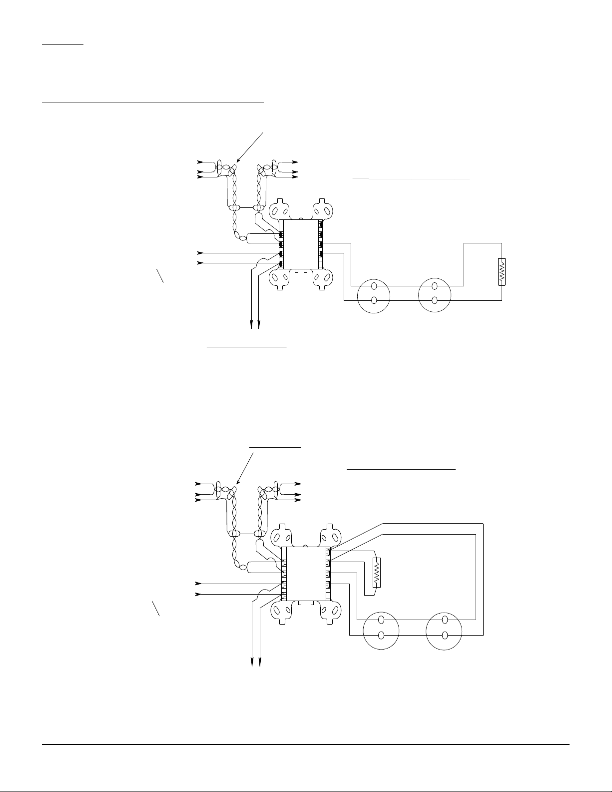
M302(A) MONITOR MODULE WIRING DIAGRAMS
CONNECT MODULES TO LISTED
COMPATIBLE ADDRESSABLE FIRE-LITE
CONTROL PANELS ONLY.
FROM PANEL OR
PREVIOUS DEVICE
LISTED BATTERY BACK-UP, SWITCHED
DC POWER SUPPLY.
SEE REQUIREMENTS ON PAGE 4.
POWER TO THE MONITOR MODULE
MUST BE EXTERNALLY SWITCHED TO
RESET THE DETECTORS. A C300
CONTROL MODULE CAN BE USED TO
SWITCH POWER FROM A STANDARD
UL LISTED POWER SUPPLY - SEE FIGURE 5.
(–)
(+)
(SHIELD)
(–)
(+)
OPTIONAL BRANCH CIRCUIT
TO NEXT INTERFACE MODULE.
MODULE SUPERVISES SUPPLY
VOLTAGE AND DETECTOR LOOP.
COMMUNICATION LINE
32 VDC MAX.
REFER TO FIRE-LITE PRODUCT MANUAL
FOR WIRE SPECIFICATIONS.
(–)
TO NEXT
(+)
(SHIELD)
(–)
(+)
ALL WIRING SHOWN IS SUPERVISED. A78-2394-631
DEVICE
MONITOR
MODULE
M302(A)
1 (–)
2 (+)
3 (–)
4 (+)
(–) 9
(+) 8
(+) 7
(–) 6
5
DETECTORS MUST BE UL LISTED COMPATIBLE WITH MODULE.
TERMINAL WIRING MUST BE POWER LIMITED.
2-WIRE CONVENTIONAL DETECTOR
INITIATING DEVICE CIRCUIT (IDC) - NFPA STYLE B
POWER LIMITED: 90ma MAX; 28 VDC MAX
IDC INSTALLATION WIRING MUST NOT EXCEED
DO NOT MIX FIRE ALARM INITIATING, SUPERVISORY,
OR SECURITY DEVICES ON THE SAME MODULE.
DO NOT LOOP WIRE UNDER TERMINALS. BREAK WIRE
RUN TO ENSURE SUPERVISION OF CONNECTIONS.
INSTALL MODULE PER MANUFACTURER'S
25 OHMS, 12 - 18 AWG.
+
–
INSTALLATION INSTRUCTIONS.
+
–
3.9K EOL
RESISTOR
(INCLUDED)
Figure 3. INTERFACE TWO-WIRE CONVENTIONAL DETECTORS, NFPA STYLE B
CONNECT MODULES TO LISTED
COMPATIBLE ADDRESSABLE FIRE-LITE
CONTROL PANELS ONLY.
FROM PANEL OR
PREVIOUS DEVICE
LISTED BATTERY BACK-UP,
SWITCHED DC POWER SUPPLY.
SEE REQUIREMENTS ON PAGE 4.
POWER TO THE MONITOR MODULE
MUST BE EXTERNALLY SWITCHED TO
RESET THE DETECTORS. A C300
CONTROL MODULE CAN BE USED TO
SWITCH POWER FROM A STANDARD
UL-LISTED POWER SUPPLY - SEE FIGURE 5.
COMMUNICATION LINE
32 VDC MAX.
REFER TO FIRE-LITE PRODUCT
(-)
(+)
MANUAL FOR WIRE SPECIFICATIONS
(-)
(+)
(SHIELD) (SHIELD)
(-)
(+)
(-)
(+)
1 (-)
2 (+)
3 (-)
4 (+)
OPTIONAL BRANCH CIRCUIT
TO NEXT MONITOR MODULE.
MODULE SUPERVISES SUPPLY
VOLTAGE AND DETECTOR LOOP.
TO NEXT
DEVICE
MONITOR
MODULE
M302(A)
TERMINAL WIRING MUST BE POWER LIMITED.
2-WIRE CONVENTIONAL DETECTOR
INITIATING DEVICE CIRCUIT (IDC) - NFPA STYLE D
POWER LIMITED: 90ma MAX; 28 VDC MAX
IDC INSTALLATION WIRING MUST NOT EXCEED
DO NOT MIX FIRE ALARM INITIATING, SUPERVISORY,
(-) 9
(+) 8
(+) 7
(-) 6
5
DO NOT LOOP WIRE UNDER TERMINALS. BREAK WIRE
RUN TO ENSURE SUPERVISION OF CONNECTIONS.
DETECTORS MUST BE UL LISTED COMPATIBLE WITH MODULE.
INSTALL DETECTORS PER MANUFACTURER'S
25 OHMS, 12 - 18 AWG.
OR SECURITY DEVICES ON THE SAME MODULE.
3.9K EOL RESISTOR
REQUIRED AT TERMINALS
8 & 9 (INCLUDED)
+
-
+
-
INSTALLATION INSTRUCTIONS.
ALL WIRING SHOWN IS SUPERVISED. A78-2395-631
Figure 4. INTERFACE TWO-WIRE CONVENTIONAL DETECTORS, NFPA STYLE D
F400-09-00 2 I56-631-06
Page 3

C300 SERIES CONTROL MODULE SWITCHING POWER SUPPLY
COMMUNICATION LINE
CONNECT MODULES TO LISTED COMPATIBLE
ADDRESSABLE FIRE-LITE CONTROL
PANELS ONLY.
FROM PANEL OR
PREVIOUS DEVICE
RELAY CONTACT RATINGS:
RESISTIVE:
INDUCTIVE:
PILOT DUTY:
2 A @ 30 VDC
1 A @ 30 VDC (.6 PF)
.6 A @ 30 VDC (.35 PF)
.3 A @ 110 VDC (.35 PF)
.3 A @ 120 VAC (.35 PF)
CONTACTS SHOWN IN STANDBY.
CONTACTS MAY HAVE SHIFTED TO THE
ACTIVATED STATE DURING SHIPPING.
CONTROL MODULE MUST BE MADE TO
COMMUNICATE WITH THE PANEL PRIOR
TO CONNECTING CIRCUITS CONTROLLED
BY THE MODULE.
(-)
(+)
(SHIELD) (SHIELD)
NORMALLY OPEN
32 VDC MAX.
SEE FIRE-LITE PRODUCT MANUAL
FOR WIRE SPECIFICATIONS
CONTROL
MODULE
C304(A)
(-)
(+)
POWER SUPPLY, LISTED FOR FIRE
PROTECTION WITH BATTERY BACKUP
(MONITOR LOSS OF PRIMARY POWER)
SEE REQUIREMENTS ON PAGE 4.
1 (-)
2 (+)
3
4
J1 & J2
FORM C RELAY OPERATION
WHEN BOTH TABS
J1 & J2 ARE BROKEN
Figure 5.
9
8
7
6
5
RELAY COMMON
(+)
(-)
(-)
TO NEXT
(+)
DEVICE
NORMALLY CLOSED
(+)
(-)
SWITCHED RISER
CIRCUIT FOR
INTERFACE MODULES
C300 CONTROL MODULE
IS NOT REQUIRED IF
SWITCHABLE POWER
IS AVAILABLE.
A2396-631
RISER POWER SUPPLY AND WIRE RESISTANCE CALCULATIONS
The power source must be capable of supplying a minimum amount of current to a riser circuit of monitor modules. It is acceptable in some jurisdictions to supply the minimum current required to allow a percentage of monitor modules to be in the alarm
state while the remaining monitor modules are in the standby state. The formulas below are provided for calculating the maximum current required from a power supply (Imax) to support a riser circuit of monitor modules with a percentage of monitor
modules in the alarm state.
Imax = Vmax/Rmin
Rmin = 2060/( 2.68
Na) + (N )
*
Where:
(Na)
is the number of monitor modules required to be supported in the alarm state; and
(N)
is the total number of monitor modules on a given riser circuit.
Example:
Na = 5, N = 15
Rmin = 72.5 = 2060/( 2.68
5) + (15 )
*
The constants were derived by reducing equations that utilize the internal resistances of the module under worst case conditions.
Designing a system where it is permitted to support a percentage of modules in the alarm state allows a longer wire run for the
riser circuit. The following formula is provided for calculating the maximum resistance (Rlmax) of the wire run for the riser circuit.
Rlmax = .085(Rmin)
The constant was derived by reducing equations that were written from a low battery supply voltage of 20.4 VDC and the minimum supply voltage of 18.8 VDC required for proper operation of the module.
The following table is provided for calculating the maximum cable length allowed for a given riser circuit if Belden cable is used.
Resistance of a pair of conductors in 1000 feet of Belden cable:
Belden 9571 (18 AWG solid copper, twisted pair) 12.6 Ω
Belden 9574 (18 AWG solid copper, twisted-shielded pair) 12.4 Ω
Belden 9572 (16 AWG solid copper, twisted pair) 8.2 Ω
Belden 9575 (16 AWG solid copper, twisted-shielded pair) 8.2 Ω
Belden 9580 (14 AWG solid copper, twisted pair) 5.0 Ω
Belden 9581 (14 AWG solid copper, twisted-shielded pair) 5.0 Ω
Belden 9582 (12 AWG solid copper, twisted pair) 3.2 Ω
Belden 9583 (12 AWG solid copper, twisted-shielded pair) 4.0 Ω
F400-09-00 3 I56-631-06
Page 4

SPECIFICATIONS
Temperature: 32° to 120° F (0° to 49° C)
Humidity: 10% to 93% Noncondensing
Weight: .5 lbs (232 gm)
"
Dimensions: 4-1/2
Test Features: Magnetically activated reed switch.
Accessories: SMB500 Surface Mount Box for 300 series modules
Communication Line – Terminals 1 & 2
Voltage: 15 – 32 VDC
Current: 200 µA Max (Standby)
Communication Line
Loop Impedance: 40 Ω Max
External Power Supply Requirements – Terminals 3 & 4
Voltage: 22.2 – 25.5 VDC (Filtered, Regulated, and Power-Limited)
Ripple: 100mV RMS Max
Current: 90 mA per module
Power must be interrupted to reset detectors. The monitor module must have a minimum of 18.8 VDC at terminals 3 and 4 to function properly. Minimum supply current and maximum wire resistance formulas are provided for a
riser circuit on page 3. Ground fault detection must be accomplished by the control panel.
H, 4" W, 1-1/4" D
(Mounts to 4
M02-04-00 Test Magnet for testing devices
1.3 mA Max (Style D enabled)
5.1 mA Max @ 24V (LED latched on)
"
square by 2-1/8" deep electrical boxes.)
Initiating Device Circuit (IDC) – Terminals 6, 7, 8, & 9
Voltage: 16 – 28 VDC (Ripple: 100mV RMS Max)
Current: 90 mA Max
IDC Loop Impedance: 25 Ω Max
Standby Current: 10.0 mA Max
Detector Current in Standby: Up to 2.4 ma
Alarm Current: 20 mA minimum
Style: Style B (class B) / Style D (class A)
EOL Resistance: 3.9K ohm nominal
Detector loop current is sufficient to ensure operation of one alarmed detector per zone. For compatible detectors refer to the Fire-Lite detector compatibility chart.
F400-09-00 4 I56-631-06
©Fire-Lite 1994
 Loading...