

Page 1
The LED-10 Series
Remote Fire Annunciators
for use with the Fire•Lite
MS-5210UD
Fire Alarm Control/Communicator
12 Clintonville Road, Northford, CT 06472
Document # 50400
10/27/97 Revision:
P/N 50400:B ECN 97-510
B
Page 2

2
Document 50400 Rev B 10/27/97 P/N 50400:B
Page 3

Contents
Section One: LED-10 Series Annunciators ...................................... 4
Features................................................................................................. 4
Figure 1-1: Component Summary......................................................... 5
Figure 1-2: Wiring to Terminals ............................................................. 6
SW1 DIP Switch Settings...................................................................... 7
Figure 1-3: SW1 DIP Switch Settings Example .................................... 7
Figure 1-4: SW2 DIP Switch Settings Example .................................... 8
Table 1-1: LED-10 Series Annunciator Addressing .............................. 9
Figure 1-5: Typical Configuration .......................................................... 9
LED Indicators and Piezo Sounder..................................................... 10
Switch Functions for LED-10 Only ...................................................... 11
Section Two: LED-10 Series Annunciators Mounting.................... 13
Figure 2-1: LED-10 Series Hardware.................................................. 13
Figure 2-2: LED-10 Series Backboxes ................................................ 13
Figure 2-3: LED-10 Series Semi-flush Mounting................................ 14
Figure 2-4: LED-10 Series Surface Mounting..................................... 15
Section Three: LED-10 Series Electrical Connections ................. 1 6
Figure 3-1: Power Connection............................................................. 1 6
Figure 3-2: LED-10IM Installation ....................................................... 1 7
Figure 3-3: EIA-485 Connection ......................................................... 1 8
Figure 3-4: Wiring FACP to LED-10 Series......................................... 19
Section Four: EIA-485 Shield Terminations ................................... 20
When the EIA-485 Shield is not in Conduit ........................................ 20
When the EIA-485 Shield is in Full Conduit ....................................... 21
Spare Slide-In Labels for LED-10 Series Annunciators................ 23
Document 50400 Rev B 10/27/97 P/N 50400:B
3
Page 4
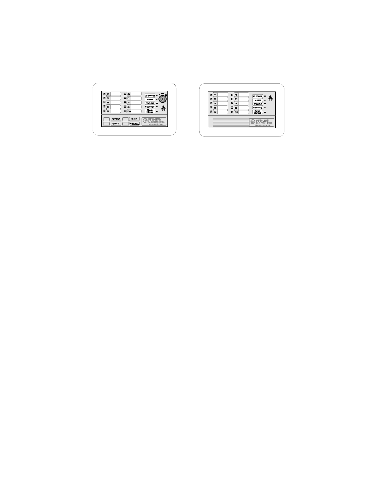
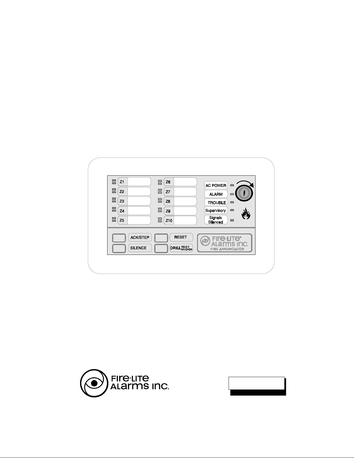
Section One: LED-10 Series Annunciators
LED-10
The Fire•Lite LED-10 Series Annunciators consist of the LED-10, LED-10L and LED10LS2. They are compact, attractive LED-type fire annunciators designed for use with
the MS-5210UD Fire Alarm Control Communicator. The LED-10L and LED-10LS2 are
models which do not have function switches or a key-switch. The LED-10LS2 is
intended primarily for Canadian installations since it provides zone 9 and 10 alarm LEDs
that are yellow for supervisory functions.
The LED-10 Series Annunciators are capable of displaying independent zone
process monitor alarm, trouble and supervisory status. They also provide system
status LEDs to display Power, Alarm, Trouble, Supervisory and Signals Silenced
conditions. The LED-10 model is also capable of performing system acknowledge,
silence, drill and reset remotely.
Communication between the control panel and the LED-10 Series Annunciators is
accomplished over a two-wire serial interface employing the EIA-485 communication
standard. Up to 32 LED-10 Series Annunciators may be connected to the two-wire EIA485 circuit. The annunciators may be powered from the host FACP or remote, UL
listed, filtered, regulated power supplies.
LED-10L and LED-10LS2
fire alarm,
Features - all models
• Zone Alarm and Trouble LEDs.
• System Status LEDs for Power (green), Alarm (red), Trouble (yellow), Supervisory
(yellow) and Signals Silenced (yellow).
• Local piezo sounder with alarm and trouble resound.
• Distinctly different flash rates for LEDs and piezo sounder distinguish system
status:
üfire alarm = 1 second on and 1 second off
üprocess monitor alarm = 1/4 second on and 1/4 second off
üsupervisory alarm = 1/2 second on and 1/2 second off
• EIA-485 connects to control panel terminal port (requires LED-10IM module).
• Plug-in terminal blocks for ease of installation and service.
• DIP switch controls transmit/receive mode.
• Up to 32 LED-10 Series Annunciators per MS-5210UD.
• Mounting options:
üSurface mount in three gang electrical box P/N: SBB-3
üSemi-flush mount in three-gang electrical box P/N: 10103 (2 3/16" min. depth)
üCan be located up to 6,000 feet (1,800 m) from the panel using 18 AWG wire
• Slide-in labels for custom labeling.
• Simple programming at MS-5210UD panel enables communications to LED-10
Series annunciators.
4
Document 50400 Rev B 10/27/97 P/N 50400:B
Page 5
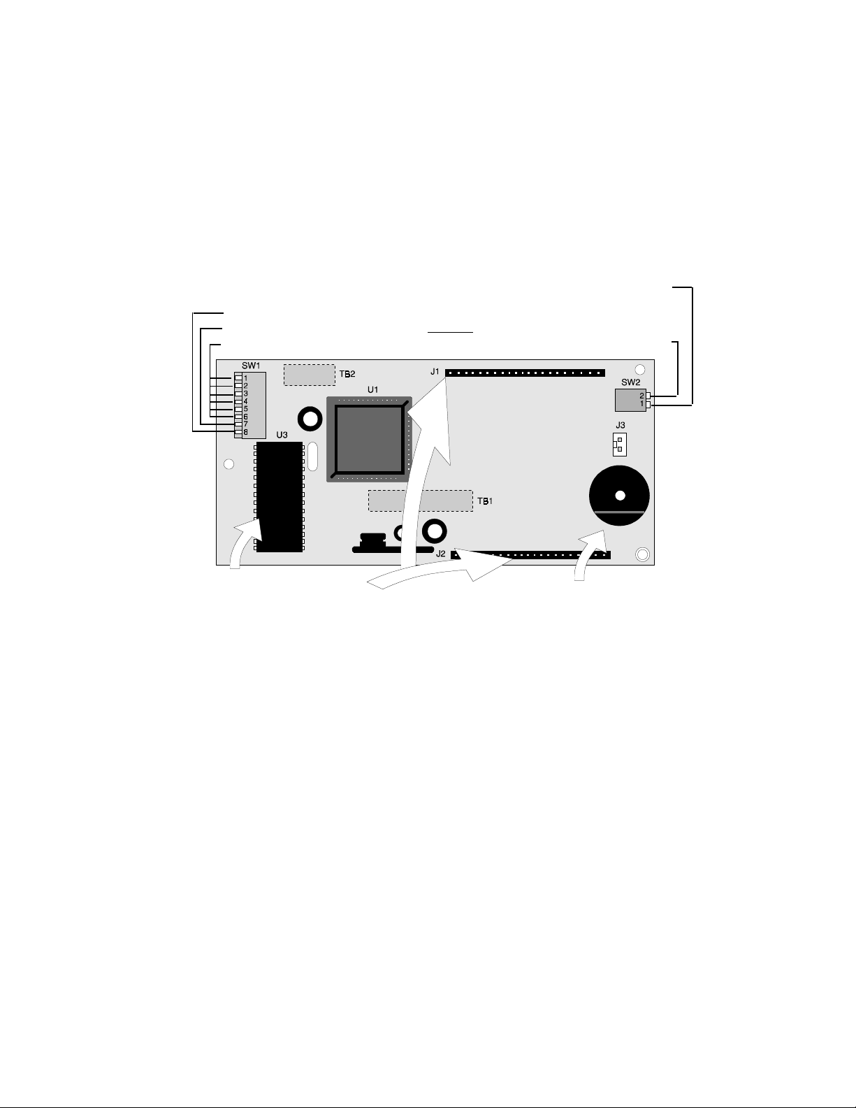
LED-10 only:
• Function switches for:
üAcknowledge üSignal Silence üDrill üSystem Reset
• Enable/Disable key-switch for function switches.
• DIP switches control local functions such as piezo enable/disable, function
switches and key-switch enable/disable.
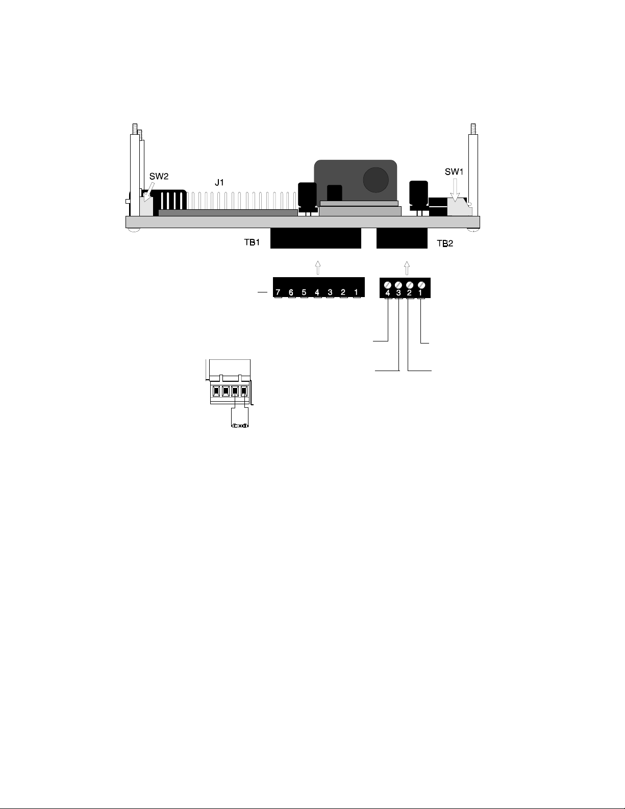
Key-switch Enable/Disable for LED-10 Only
Receive-Transmit/Receive only
not used
LED-10 Series Address
Note: TB1 & TB2 are
located on backside of PCB
(not used on the LED-10L or LED-10LS2)
Top view
Piezo Enable/Disable
ROM
Membrane Connectors
Membrane switch connectors
Figure 1-1: Component Summary
Piezo Sounder
The LED-10 Series sounder, if enabled, will be activated
when any new alarm or trouble is received from the
panel. It is silenced by pressing an ACKNOWLEDGE or
SILENCE switch. Piezo must not be disabled without
approval of LAHJ (Local Authority Having Jurisdiction).
Document 50400 Rev B 10/27/97 P/N 50400:B
5
Page 6
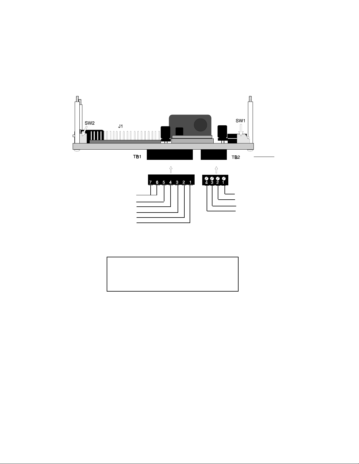
Side view
(rotated 180
from above
[Top] view)
o
Earth Ground Option
-24 VDC OUT
-24 VDC IN
+24 VDC OUT
+24 VDC IN
No connection
+EIA-485
-EIA-485
Shield
No connection
Note: These connections must be power-limited and the +24 volt nominal power (18 VDC to 26 VDC)
must be filtered.
Current Consumption @ 24 VDC nominal (filtered)
Normal/Standby (no activity): 23 mA
Trouble Condition: 31 mA
Alarm: 28 mA (1 zone in alarm)
40 mA (all 10 zones in alarm)
AC Fail: 24 mA
Figure 1-2: Wiring to Terminals
6
Document 50400 Rev B 10/27/97 P/N 50400:B
Page 7
SW1 DIP Switch Settings
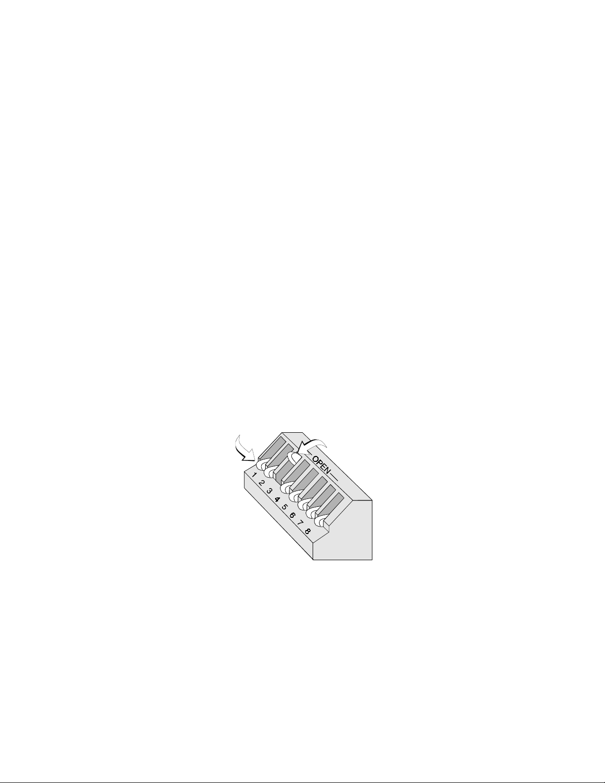
The OPEN position on SW1 is the OFF state. Refer to Figure 1-3 for an explanation of
DIP switch positions. SW1 switch settings are as follows:
1 through 6 - LED-10 Series annunciator address switches.
The first six switches are used to set the address of the annunciator. The OFF
(OPEN) up position equals a binary 1 and the ON down position equals a
binary 0. Refer to Table 1-1 for information on setting these switches for
specific addresses. Each LED-10 Series annunciator connected to the EIA485 communication bus must have a unique address.
7 - Not used
8 - ON = Receive/Transmit, OFF (OPEN) = Receive Only
Switch 8 set to ON position enables Receive/Transmit mode for the LED-10
Series annunciator. This allows the annunciator to receive and display system
status information and to transmit supervision status. It also allows the LED-10
model to transmit system control data such as Acknowledge/Step, Reset,
Signal Silence and Drill. Switch 8 set to the OFF position enables Receive
Only mode which allows the annunciator to receive and display system status
information but prevents supervision status from being transmitted back to the
FACP. It also prevents function switch operation on the LED-10 model. To
ensure annunciator supervision for all LED-10 Series annunciators and
function switch capability for the LED-10 model, each annunciator connected to
the EIA-485 communication bus must have a unique address and should be
set to enable Receive/Transmit Mode.
DOWN POSITION = ON
NOTE - SW1 DIP switch settings as illustrated in Figure 1-3 are as follows:
1) DIP switches 1 - 6: Address 08 (see Table 1-1).
2) DIP switch 7: Not used.
3) DIP switch 8: ON = Receive/Transmit
UP (OPEN) POSITION = OFF
Figure 1-3: SW1 DIP Switch Settings Example
Document 50400 Rev B 10/27/97 P/N 50400:B
7
Page 8
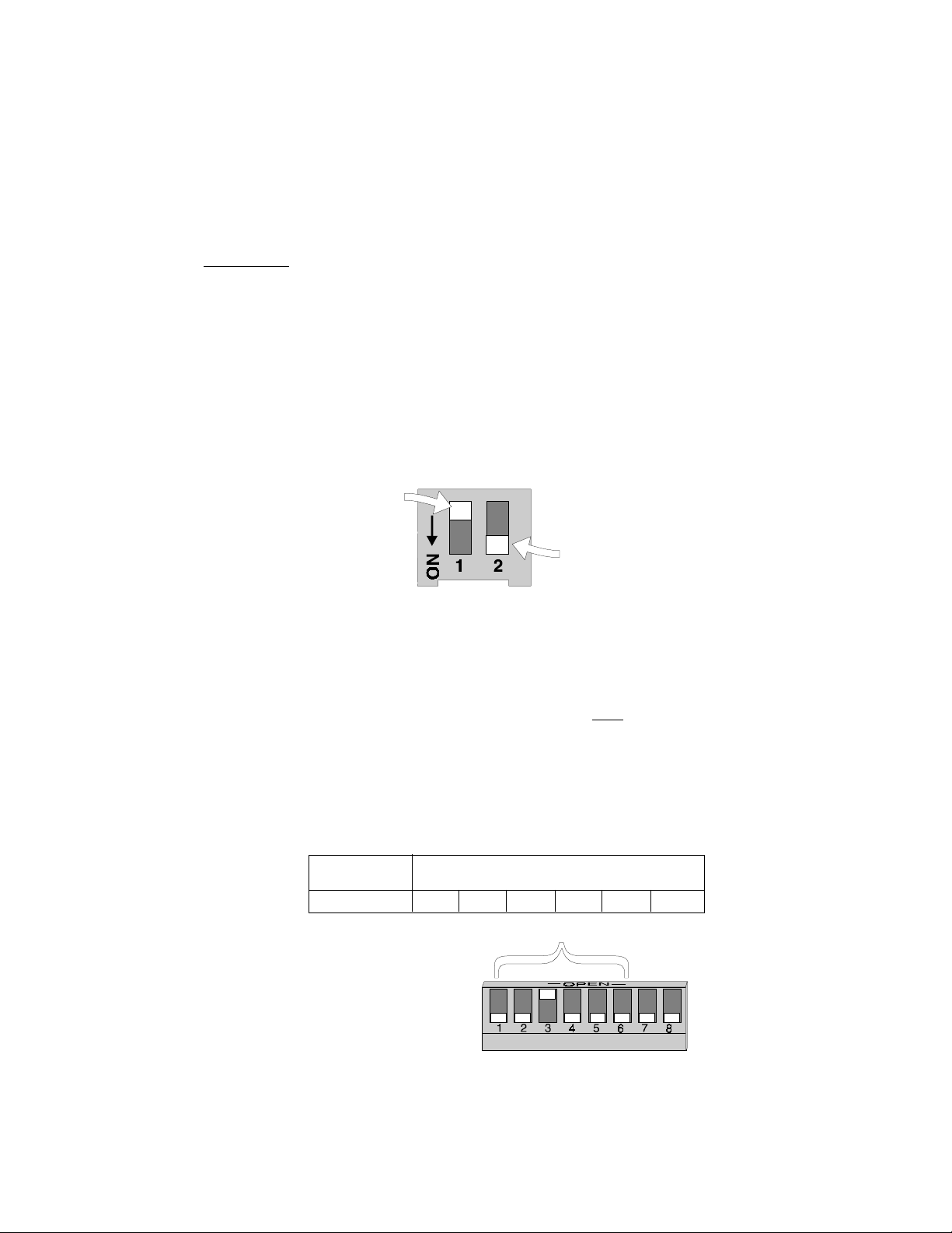
SW2 DIP Switch Settings
SW2 switch settings are as follows:
1 - LED-10 Only (not used on LED-10L and LED-10LS2)
ON = Key-switch Enable, OFF = Key-switch Disable.
Switch 1 set to the ON position enables the key-switch operation. The keyswitch may now be used to enable LED-10 model membrane (control) switches,
allowing remote switch functions, or lockout the switches, preventing remote
switch functions. Switch 1 set to the OFF position disables the key-switch
operation. Refer to Operation Section for key-switch function description.
2 - ON = Piezo sounder enabled, OFF = Piezo sounder disabled.
CAUTION: Piezo sounder must not be disabled without prior approval of the
Local Authority Having Jurisdiction.
UP POSITION = OFF
DOWN POSITION = ON
Figure 1-4: SW2 DIP Switch Settings Example
LED-10 Series Addressing
SW1 DIP switches 1 through 6 are used for addressing the LED-10 Series annunciators.
Each device connected to the EIA-485 communication bus must have a unique
address.
and for individual supervision of each annunciator by the FACP. Switch settings and
the corresponding addresses are shown in Table 1-1. (Address '00' is invalid).
Note: 1 = Switch in the UP (OPEN) position.
8
This allows specific data to be transmitted between the FACP and that device
0 = Switch in the DOWN position.
Example: ADDRESS SWITCH SETTINGS
1 2 3 4 5 6
08 0 0 1 0 0 0
Addressing Switches
Document 50400 Rev B 10/27/97 P/N 50400:B
Page 9
ADDRESS SWITCH SETTINGS ADDRESS SWITCH SETTINGS
1 2 3 4 5 6 1 2 3 4 5 6
INVALID 0 0 0 0 0 0 17 0 1 0 0 0 1
01 0 0 0 0 0 1 18 0 1 0 0 1 0
02 0 0 0 0 1 0 19 0 1 0 0 1 1
03 0 0 0 0 1 1 20 0 1 0 1 0 0
04 0 0 0 1 0 0 21 0 1 0 1 0 1
05 0 0 0 1 0 1 22 0 1 0 1 1 0
06 0 0 0 1 1 0 23 0 1 0 1 1 1
07 0 0 0 1 1 1 24 0 1 1 0 0 0
08 0 0 1 0 0 0 25 0 1 1 0 0 1
09 0 0 1 0 0 1 26 0 1 1 0 1 0
10 0 0 1 0 1 0 27 0 1 1 0 1 1
11 0 0 1 0 1 1 28 0 1 1 1 0 0
12 0 0 1 1 0 0 29 0 1 1 1 0 1
13 0 0 1 1 0 1 30 0 1 1 1 1 0
14 0 0 1 1 1 0 31 0 1 1 1 1 1
15 0 0 1 1 1 1 32 1 0 0 0 0 0
16 0 1 0 0 0 0
Table 1-1: LED-10 Series Annunciator Addressing
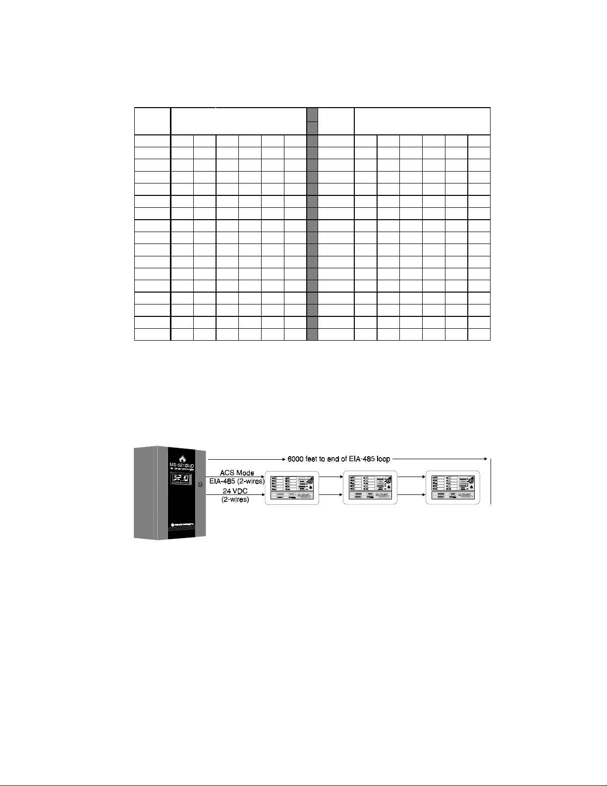
Typical Configuration
The LED-10 Series annunciators indicate the status of the MS-5210UD, display zone
status and require no programming. In addition, the LED-10 model offers multiple
annunciator locations with the capability of remote Acknowledge, Signal Silence, Drill
and Reset functions.
NOTES:
1) EIA-485: Maximum of 6,000 feet (1,800 m) total cable length from FACP to LED-10 Series
annunciators. Circuit is power-limited.
2) Up to 32 LED-10 Series annunciators may be used on the EIA-485 circuit. The MS-5210UD
can power a maximum of seven annunciators. If additional annunciators are connected, the
Fire•Lite FCPS-24F may be used to supply additional power. (Power supplies used for this
purpose must have their negative terminals commoned together).
3) Between each annunciator are four wires: A twisted-shielded pair for data communications and
a pair for 24 VDC power.
4) A mix of LED-10 Series annunciators can be connected to the same EIA-485 circuit.
Figure 1-5: Typical Configuration
Document 50400 Rev B 10/27/97 P/N 50400:B
9
Page 10

LED Indicators and Piezo Sounder
The LED-10 Series annunciators provide LEDs which indicate the system and zone
status of its associated MS-5210UD fire alarm control panel.
AC Power
This is a green LED which illuminates if AC power is
applied to the host FACP. The green LED will turn
off if AC power to the host FACP is lost.
Alarm
This is a red LED that flashes (1 second on, 1
second off) when one or more fire alarms occur. The
piezo sounder turns on steady for alarm. The LED
illuminates steadily and the piezo silences when an
Acknowledge or Silence switch is pressed. The
Alarm LED turns off when the Reset switch is
pressed after the alarm condition has been cleared.
Trouble
This is a yellow LED that flashes (1 second on, 1
second off) when one or more trouble conditions
occur. The piezo sounder pulses (1 second on, 1
second off). The LED turns on steady and the piezo
silences when an Acknowledge or Silence switch is
pressed. The LED turns off when all trouble conditions are cleared. This LED will
also illuminate if the microprocessor watchdog circuit within the annunciator is
activated.
Supervisory
This is a yellow LED that flashes (½ second on, ½
second off) when one or more supervisory conditions
occur, such as a sprinkler valve tamper condition.
The piezo sounder pulses (½ second on, ½ second
off). The LED illuminates steadily and the piezo silences when an Acknowledge or
Silence switch is pressed. The Supervisory LED turns off when a Reset switch is
pressed after clearing the supervisory condition.
LED-10 and LED-10L Only
Zone Alarm - Zones 1 through 10
This is a red LED that flashes when a fire alarm,
supervisory alarm or process monitoring alarm
occurs on the corresponding zone. The LED flashes
at a 1 second on/1 second off rate for a fire alarm
condition, a ½ second on/½ second off rate for a supervisory alarm and a ¼ second
on/¼ second off rate for a process monitoring alarm. The piezo sounder will pulse
at a rate corresponding to the flashing LED. The LED illuminates steadily and the
piezo silences when an Acknowledge or Silence switch is pressed. The LED turns
off when the fire alarm, process monitoring alarm or supervisory alarm is cleared on
the corresponding zone and the Reset switch is pressed.
Note: Be certain to use customized slide-in label to identify the zone function, since
the red LED will flash for a variety of conditions as programmed in the FACP. Refer
to the MS-5210UD Manual P/N 50193 for details.
10
Document 50400 Rev B 10/27/97 P/N 50400:B
Page 11
LED-10LS2 Only
Zone Alarm - Zones 1 through 8
The red LED for Zones 1 through 8 on the
LED-10LS2 operate the same as on the
LED-10 and LED-10L. Refer to the previous
section.
Zone Alarm - Zones 9 and 10
This is a yellow LED on Zones 9 and 10 of the LED-10LS2 only. These two zones
should be used to annunciate supervisory alarms only. Approval from the Local
Authority Having Jurisdiction is required in order to annunciate fire alarms or
process monitor alarms on these zones. The LED flashes at a ½ second on/½
second off rate for a supervisory alarm. The piezo sounder will pulse at a rate
corresponding to the flashing LED. The LED illuminates steadily and the piezo
silences when an Acknowledge or Silence switch is pressed. The LED turns off
when the supervisory alarm is cleared on the corresponding zone and the Reset
switch is pressed.
Zone Trouble - Zones 1 through 10 (All LED-10 Series)
This is a yellow LED that flashes when a zone
trouble condition occurs on the corresponding zone. The LED flashes at a 1 second on/
1 second off rate for a zone trouble condition. The piezo sounder will pulse at a rate
corresponding to the flashing LED. The LED illuminates steadily and the piezo
silences when the Acknowledge or Silence switch is pressed. The LED turns off
when all trouble conditions on the corresponding zone are cleared.
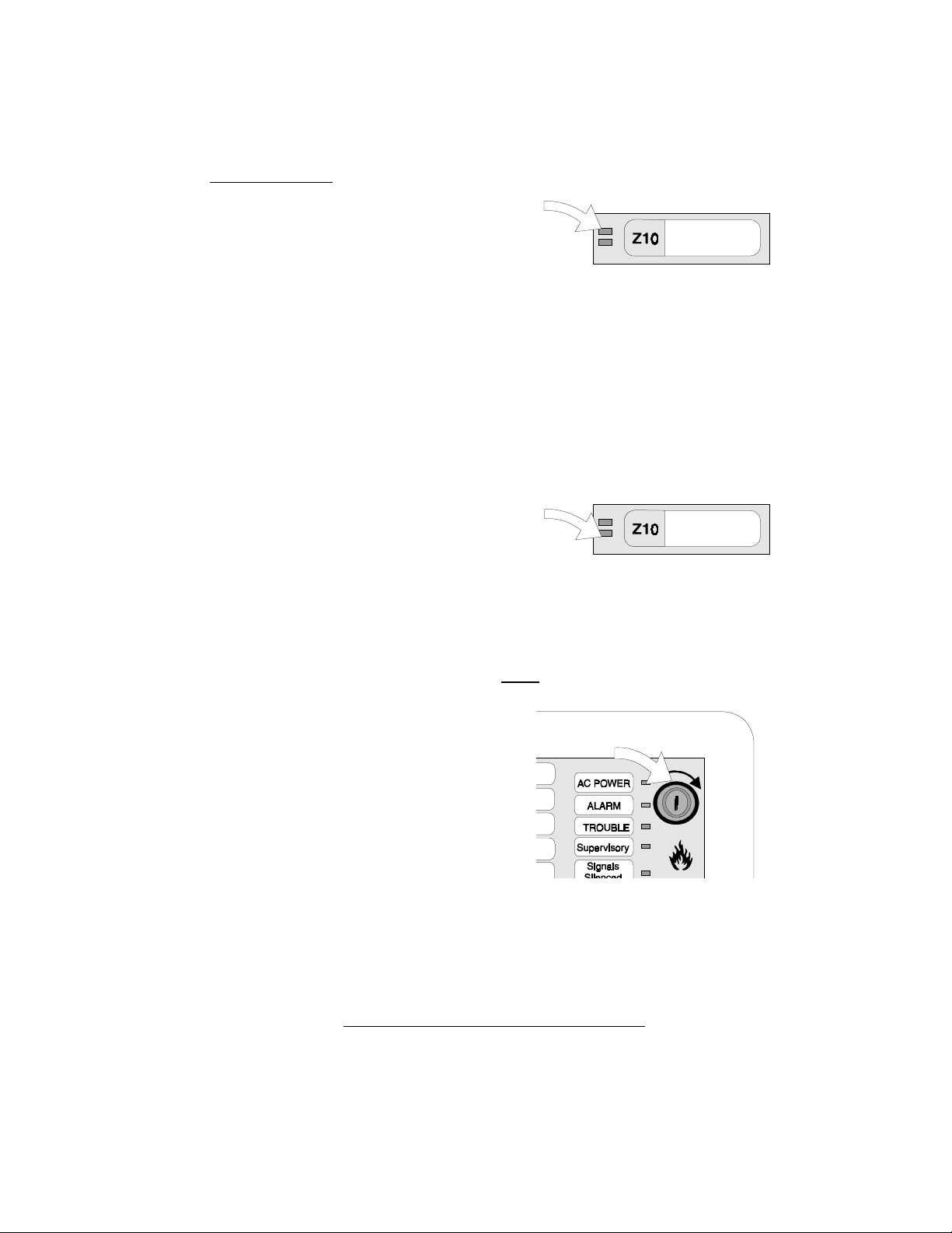
Switch Functions for LED-10 Model Only
Key-switch
The key-switch is used to enable and
disable the operation of the membrane
(control) switches if switch 1 on DIP switch
SW2 has been placed to the ON position.
To enable the Acknowledge, Silence, Drill
and Reset function switches, insert a
standard Fire•Lite key into the key-switch
located at the top right corner of the LED-
10. Make certain the key is inserted
completely before attempting to turn it.
Turn the key clockwise until it stops. Leave the key inserted while pressing the
function switches. When finished with the function switches, turn key-switch
counterclockwise to disable function switches.
Note: The key-switch should normally be in the disabled position (fully counterclockwise), with the key removed and access to the key restricted to authorized
personnel only. Do not leave the key unattended in the LED-10.
Document 50400 Rev B 10/27/97 P/N 50400:B
Key-switch
(shown in Off Position)
11
Page 12

Acknowledge
When the Acknowledge switch is pressed and
released, the LED-10 sends an Acknowledge
command to the control panel. Pressing the Acknowledge switch silences the local piezo sounder,
the sounders located in all other system annunciators and the sounder located on the Fire Alarm Control Panel's main circuit board.
It will also change all flashing system LEDs to steady on. Only one press is
necessary regardless of the number of new alarms, troubles or supervisory signals.
An acknowledge message is also sent to the printer and the history files in the
MS-5210UD.
Silence
When the Silence switch is pressed and released,
the LED-10 sends a Signal Silence command to the
control panel. The Silence switch performs the
same functions as the Acknowledge switch. In
addition, if an alarm exists, it turns off all
NAC outputs only and causes the FACP ALARM SILENCE LED and the LED-10
SIGNAL SILENCE LED to turn on. It also sends an ALARM SILENCED message to
the printer and the history file within the MS-5210UD. A subsequent new alarm will
resound the appropriate Notification Appliance Circuits (NACs) and local sounders.
silenceable
Drill: Hold 2 Sec.
When the Drill switch is pressed and held for at least
two seconds (time required to prevent accidental
activations), the LED-10 will transmit a drill command to the control panel. This command causes
the FACP to turn on all main panel NAC outputs. In
the event that the system was previously silenced, the drill command will also turn
off the ALARM SILENCE LED. (The Silence switch operates on
outputs only).
silenceable
NAC
Reset
When the System Reset switch is pressed and
released, the LED-10 sends a Reset command to the
control panel. This will turn off all Notification Appliance Circuits, temporarily turns off resettable power to
4-wire detectors, and sends a "SYSTEM RESET'
message to the FACP display, printer and MS-5210UD history files. It also turns on
all system LEDs, piezo sounders and FACP LED display segments as long as the
Reset switch is held (lamp test). Any alarm or trouble that exists after a Reset will
resound the system.
12
Document 50400 Rev B 10/27/97 P/N 50400:B
Page 13

Section Two: Mounting LED-10 Series Annunciators
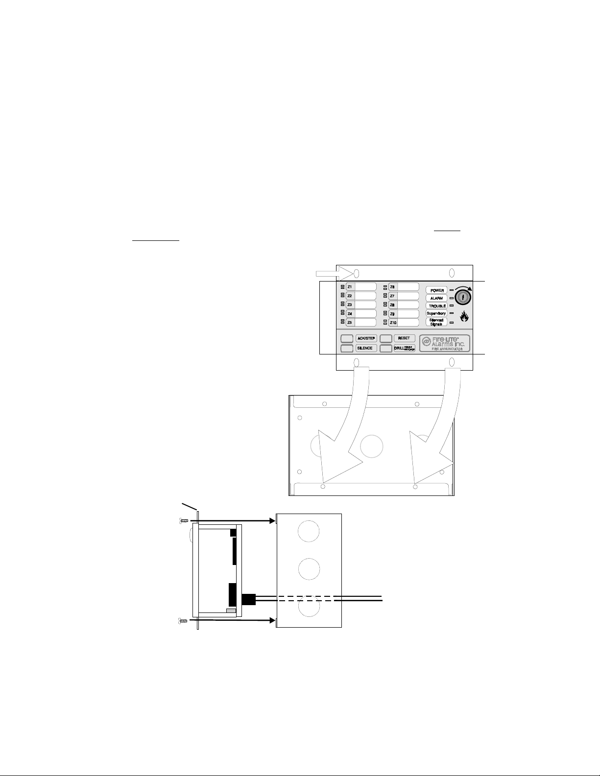
Screw
LED-10 Series Annunciator Preparation
The LED-10 Series can be surface mounted in
a three-gang electrical box, Fire•Lite P/N SBB-3
or semi-flush mounted in a three-gang electrical
box, Fire•Lite P/N 10103 or equivalent, with a
minimum depth of 2 3/16". Select and remove
the appropriate knockout(s), pull the necessary
wires through the knockouts and mount the
three-gang box in or on the wall depending on
the type of installation desired.
power is not applied to the wiring during the
installation procedure.
Note: To ensure static protection, all enclosures, including the LED-10 Series electrical
box, must be connected to earth ground! Never use the shield of the communications
wiring for static protection.
To mount the LED-10 Series Annunciator in the electrical box, the trim ring must first be
removed. The trim ring is held in place by two screws inserted through the top and
bottom edge as illustrated above. Removal of the trim ring will expose a metal flange
with mounting holes.
Be certain that
Screw
LED-10 Series flange
LED-10 Series Trim ring
(P/N 23165)
Figure 2-1: LED-10 Series Hardware
3-Gang Electrical Box P/N: 10103
(semi-flush mount)
Figure 2-2: LED-10 Series Backboxes
Document 50400 Rev B 10/27/97 P/N 50400:B
3-Gang Electrical Box P/N: SBB-3
(surface mount)
13
Page 14

Semi-flush Mount Backbox
Remove the plug-in terminal blocks from the LED-10 Series circuit board. Connect the
EIA-485 and power wiring into the terminal block positions illustrated in Figures 3-1 and
3-3. Plug the terminal blocks back into the TB1 and TB2 connectors on the back of the
annunciator circuit board.
Set DIP switches SW1 and SW2 for the desired options (refer to switch settings in
Figures 1-3, 1-4 and Table 1-1).
Mount the LED-10 Series to the three-gang electrical box using the four mounting holes
on the annunciator flange and the four screws provided for this purpose. Replace the
trim ring and secure with the two screws which were previously removed. Adjust the
plastic trim ring to the surface of the wall before tightening the screws.
tighten.
LED-10 Series flange
Mounting Holes (4)
Do not over-
Three-gang electrical box
(Fire•Lite P/N 10103 or equivalent
with 2 3/16" minimum depth).
flange
LED-10 Series
Figure 2-3: Semi-flush Mounting
14
EIA-485 and power wiring
Document 50400 Rev B 10/27/97 P/N 50400:B
Page 15
Surface Mount Backbox
Remove the plug-in terminal blocks from the LED-10 Series circuit board. Connect the
EIA-485 and power wiring into the terminal block positions illustrated in Figures 3-1 and
3-3. Plug the terminal blocks back into the TB1 and TB2 connectors on the back of the
annunciator circuit board.
Set DIP switches SW1 and SW2 for the desired options (refer to switch settings in
Figures 1-3, 1-4 and Table 1-1).
Mount the LED-10 Series to a three-gang electrical box using the four mounting holes
on the annunciator flange and the four screws provided for this purpose. Replace the
trim ring and secure with the two screws which were previously removed.
overtighten.
LED-10 Series flange
Mounting Holes (4)
Do not
Three-gang electrical box
(Fire•Lite P/N SBB-3 or equivalent
with 2.75" minimum depth).
flange
LED-10 Series
Figure 2-4: Surface Mounting
Document 50400 Rev B 10/27/97 P/N 50400:B
EIA-485 and power wiring
15
Page 16

Section Three: LED-10 Series Electrical Connections
The LED-10 Series Annunciators can be powered by the MS-5210UD power output or
from a remote, UL listed, filtered power supply such as the Fire•Lite FCPS-24F. The
power run to the LED-10 Series must be power-limited but need not contain a power
supervision relay since loss of power is inherently supervised through loss of communication with the annunciator. Maximum LED-10 Series current draw from the power
supply under alarm condition is 28 mA. Maximum current draw from the control panel's
secondary power source (batteries) under loss of AC power is 24 mA.
LED-10 Series
Plug-in terminal blocks
Earth Ground Option
Note: All connections are power-limited and supervised.
Figure 3-1: Power Connection
16
Document 50400 Rev B 10/27/97 P/N 50400:B
n/c
+ 24 VDC
From Main Power Supply
- 24 VDC
+ 24 VDC
To next annunciator or ACM-8RF
- 24 VDC
Page 17

LED-10IM
The LED-10IM Interface Module provides an EIA-485 port to support the LED-10 Series,
AFM Series and LDM Series annunciators as well as the ACM-8RF Remote Relay
Module and is therefore required when connecting these devices to the MS-5210UD.
The MS-5210UD supervises EIA-485 wiring for open circuits via the LED-10IM Interface
Module. The LED-10IM plugs into connector J6 located in the upper right corner of the
MS-5210UD main circuit board.
Install the two supplied standoffs into the FACP main circuit board. Ensure that the
metal standoff is installed in the position indicated in the illustration below. Carefully
align the two connectors and press the LED-10IM module securely into place. Make
certain the pins are properly aligned to prevent bending or breaking of any pins. It is
important that the supplied screw and washer be used to secure the module to the
metal standoff. This is necessary in order to help protect against electrical transients.
Note: Refer to the MS-5210UD Manual Programming Section for information on programming the LED-10 Series Annunciators into the system.
LED-10IM
Figure 3-2: LED-10IM Installation
MS-5210UD
Document 50400 Rev B 10/27/97 P/N 50400:B
Metal
Standoff
17
Page 18
LED-10 Series
Plug-in terminal blocks
No connection
Shield
+ EIA-485
- EIA-485
TB2
Refer to Note 6
Notes:
1) All connections are power-limited and supervised.
2) A maximum of 32 LED-10 Series Annunciators may be connected to this circuit.
3) 6,000 feet (1,800 m) maximum distance @ 18 AWG (0.75 mm2) between the panel and
annunciators.
4) Use overall foil/braided-shield twisted pair cable suitable for EIA-485 applications (refer to Section
Four for shield termination information).
5) The EIA-485 circuit is rated at 5.5 VDC maximum and 60 mA maximum.
6) The LED-10 Series Annunciators must have the supplied R120 (120 ohm) resistor installed
across the EIA-485 terminals on the last or only device connected to the EIA-485 bus as shown.
The resistor is required for impedance matching.
Figure 3-3: EIA-485 Connection
18
Document 50400 Rev B 10/27/97 P/N 50400:B
Page 19

Terms 1 (+)
and 2 (-)
EIA-48524 VDC TB2
LED-10IM
MS-5210UD
LED-10 Series in grounded box
LED-10 Series in grounded box
Refer to Note 4
CAUTION! Please be certain to secure the LED-10IM module to the MS-5210UD and to keep all
wiring from mechanically interfering with the LED-10IM.
Note:
1) Twisted, shielded wire is recommended for the EIA-485 communications loop.
2) Four-conductor, overall shielded wire may be used for the four EIA-485 wires and the two power
wires. It is, however, strongly recommended that the power and communication wires be
separate whenever possible.
3) Refer to Figures 3-1, 3-2 and 3-3 for LED-10 Series and LED-10IM terminal designations.
4) The LED-10 Series Annunciators must have the supplied R120 (120 ohm) resistor installed
across the EIA-485 terminals on the last or only device connected to the EIA-485 bus as shown.
The resistor is required for impedance matching.
Figure 3-4: Wiring FACP to LED-10 Series Annunciator
Document 50400 Rev B 10/27/97 P/N 50400:B
19
Page 20

Section Four: EIA-485 Shield Terminations
The EIA-485 circuit must be wired using a twisted-shielded pair cable having a characteristic impedance of 120 ohms, +/- 20%. Do not run cable adjacent to, or in the same
conduit as, 120-volt AC service, noisy electrical circuits that are powering mechanical
bells or horns, audio circuits above 25 V
Note: To ensure static (ESD - electrostatic discharge) protection, all enclosures,
including the LED-10 Series electrical box, must be connected to earth ground! Never
use the EIA-485 shield for this purpose. The EIA-485 shield is for radiated noise
emission protection (RFI, EMI). Refer to the following figures.
The EIA-485 shield should be terminated as follows:
When the EIA-485 shield is not in conduit: The EIA-485 loop allows the FACP to
communicate with the annunciators. The shield for the EIA-485 loop must be
connected to earth ground at the FACP but must be left floating (no connection) at
the annunciator if it is the first or only device on the EIA-485 loop. If a second
annunciator is connected, the shield leaving the first annunciator must be left
floating. The shield entering the second annunciator must be connected to the 3gang box or Earth Ground terminal (TB1-6 & 7) on the second annunciator. If
additional annunciators are connected, the shield leaving each enclosure must be
left floating and the shield entering each must be connected to the 3-gang box or
the Earth Ground Terminal (TB1-6 & 7) on the annunciator.
Connect the drain wire to the
outside of the MS-5210UD cabinet
via a BX-type connector.
, motor control circuits, or SCR power circuits
RMS
20
Shield Drain Wire
FACP BackboxFACP Backbox
FACP Backbox
FACP BackboxFACP Backbox
Series
Document 50400 Rev B 10/27/97 P/N 50400:B
Series
(+) EIA-485
(-) EIA-485
FACP
Series
Page 21

When the EIA-485 shield is in full conduit: The EIA-485 loop allows the FACP to
communicate with the annunciator(s). The shield for the EIA-485 loop must be
connected to earth ground at the FACP, but must be left floating (no connection) at
the annunciator if it is the first or only device on the EIA-485 loop. If a second
annunciator is connected, the shield leaving the first annunciator must be left
floating. The shield entering the second annunciator must be connected to the
Earth Ground Terminal (TB1- 6 & 7) on the second annunciator. If additional
annunciators are connected, the shield leaving each annunciator must be left
floating and the shield entering the following unit must be connected to the Earth
Ground Terminal (TB1 - 6 & 7) on the annunciator.
Caution! Do not allow the floating (no connection) end of the shield to contact the
conduit. The floating end should be insulated from earth ground.
Connect the shield drain wire to the Earth
Ground Terminal on the annunciator.
LED-10 Series Box
Shield Drain Wire
Series
LED-10
Series
TB2-1 (+) EIA-485
TB2-2 (-) EIA-485
TB1-6 Earth Ground
(IN)
Series Series
Notes:
1) Power-limited 24 VDC regulated power may be run in the same conduit as the EIA-485 wiring.
2) Twisted, shielded wire is recommended for the EIA-485 communications loop.
3) Each LED-10 Series Annunciator's electrical backbox is connected to earth ground via the
conduit.
4) Shield is connected to the FACP cabinet (earth ground) leaving the FACP.
Document 50400 Rev B 10/27/97 P/N 50400:B
21
Page 22

Notes
22
Document 50400 Rev B 10/27/97 P/N 50400:B
Page 23

Slide-In Labels for the LED-10 Series Annunciators
Slide-in labels for Zones 1-10 are included with the LED-10 Series Annunciators. In
the event that these labels are damaged or lost, remove this page from the manual
and type the appropriate information on the labels shown below. Type on the lines
provided to ensure centering of information in label windows. Carefully cut out the
labels and insert them into the two label slots on the top left side of the annunciator
face plate.
Label #1 Label #2
Note: To ensure the best fit, cut directly along the dotted line surrounding
each label.
Custom User
Label #1
Custom User
Label #2
Custom User
Label #1
Document 50400 Rev B 10/27/97 P/N 50400:B
Custom User
Label #2
23
Page 24

Notes
24
Document 50400 Rev B 10/27/97 P/N 50400:B
Page 25

Notes
Document 50400 Rev B 10/27/97 P/N 50400:B
25
Page 26

Notes
26
Document 50400 Rev B 10/27/97 P/N 50400:B
Page 27

Document 50400 Rev B 10/27/97 P/N 50400:B
27
Page 28

28
Document 50400 Rev B 10/27/97 P/N 50400:B
 Loading...