

Page 1

PN 50055:C0 ECN 01-155
Lamp Driver Module
LDM-32F
Instruction Manual
Document 50055
03/20/2001 Rev:
C
Page 2

Fire Alarm System Limitations
An automatic fire alarm system–typically made up of
smoke detectors, heat detectors, manual pull stations,
audible warning devices, and a fire alarm control with
remote notification capability–can provide early warning
of a developing fire. Such a system, however, does not
assure protection against property damage or loss of life
resulting from a fire.
The Manufacturer recommends that smoke and/or heat
detectors be located throughout a protected premise
following the recommendations of the current edition of
the National Fire Protection Association Standard 72
(NFPA 72), manufacturer's recommendations, State and
local codes, and the recommendations contained in the
Guide for Proper Use of System Smoke Detectors, which
is made available at no charge to all installing dealers.
A study by the Federal Emergency Management Agency
(an agency of the United States government) indicated
that smoke detectors may not go off in as many as 35%
of all fires. While fire alarm systems are designed to
provide early warning against fire, they do not guarantee
warning or protection against fire. A fire alarm system
may not provide timely or adequate warning, or simply
may not function, for a variety of reasons:
Smoke detectors may not sense fire where smoke
cannot reach the detectors such as in chimneys, in or
behind walls, on roofs, or on the other side of closed
doors. Smoke detectors also may not sense a fire on
another level or floor of a building. A second-floor
detector, for example, may not sense a first-floor or
basement fire.
Particles of combustion or "smoke" from a developing
fire may not reach the sensing chambers of smoke
detectors because:
• Barriers such as closed or partially closed doors,
walls, or chimneys may inhibit particle or smoke flow.
• Smoke particles may become "cold," stratify, and not
reach the ceiling or upper walls where detectors are
located.
• Smoke particles may be blown away from detectors
by air outlets.
• Smoke detectors may be drawn into air returns before
reaching the detector.
The amount of "smoke" present may be insufficient to
alarm smoke detectors. Smoke detectors are designed
to alarm at various levels of smoke density. If such
density levels are not created by a developing fire at the
location of detectors, the detectors will not go into alarm.
Smoke detectors, even when working properly, have
sensing limitations. Detectors that have photoelectronic
sensing chambers tend to detect smoldering fires better
than flaming fires, which have little visible smoke.
Detectors that have ionizing-type sensing chambers
tend to detect fast-flaming fires better than smoldering
fires. Because fires develop in different ways and are
often unpredictable in their growth, neither type of detector is necessarily best and a given type of detector may
not provide adequate warning of a fire.
Smoke detectors cannot be expected to provide
adequate warning of fires caused by arson, children
playing with matches (especially in bedrooms), smoking
in bed, and violent explosions (caused by escaping gas,
improper storage of flammable materials, etc.).
While a fire alarm system may lower insurance
rates, it is not a substitute for fire insurance!
Heat detectors do not sense particles of combustion and
alarm only when heat on their sensors increases at a
predetermined rate or reaches a predetermined level.
Rate-of-rise heat detectors may be subject to reduced
sensitivity over time. For this reason, the rate-of-rise
feature of each detector should be tested at least once
per year by a qualified fire protection specialist.
detectors are designed to protect property, not life.
IMPORTANT!
the same room as the control panel and in rooms used
by the system for the connection of alarm transmission
Smoke detectors must be installed in
wiring, communications, signaling, and/or power.
detectors are not so located, a developing fire may damage the alarm system, crippling its ability to report a fire.
Audible warning devices such as bells may not alert
people if these devices are located on the other side of
closed or partly open doors or are located on another
floor of a building. Any warning device may fail to alert
people with a disability or those who have recently consumed drugs, alcohol or medication. Please note that:
• Strobes can, under certain circumstances, cause
seizures in people with conditions such as epilepsy.
• Studies have shown that certain people, even when
they hear a fire alarm signal, do not respond or
comprehend the meaning of the signal. It is the
property owner's responsibility to conduct fire drills
and other training exercise to make people aware of
fire alarm signals and instruct them on the proper
reaction to alarm signals.
• In rare instances, the sounding of a warning device
can cause temporary or permanent hearing loss.
A fire alarm system will not operate without any
electrical power. If AC power fails, the system will
operate from standby batteries only for a specified time
and only if the batteries have been properly maintained
and replaced regularly.
Equipment used in the system may not be technically
compatible with the control. It is essential to use only
equipment listed for service with your control panel.
Telephone lines needed to transmit alarm signals from
a premise to a central monitoring station may be out of
service or temporarily disabled. For added protection
against telephone line failure, backup radio transmission
systems are recommended.
The most common cause of fire alarm malfunction is
inadequate maintenance. To keep the entire fire alarm
system in excellent working order, ongoing maintenance
is required per the manufacturer's recommendations,
and UL and NFPA standards. At a minimum, the
requirements of Chapter 7 of NFPA 72 shall be followed.
Environments with large amounts of dust, dirt or high air
velocity require more frequent maintenance. A maintenance agreement should be arranged through the local
manufacturer's representative. Maintenance should be
scheduled monthly or as required by National and/or
local fire codes and should be performed by authorized
professional fire alarm installers only. Adequate written
records of all inspections should be kept.
Heat
If
LimWarSm.p65 01/10/2000
Page 3

Installation Precautions
WARNING -
connected to the fire alarm control panel.
sources of power before servicing. Control unit and
associated equipment may be damaged by removing
and/or inserting cards, modules, or interconnecting
cables while the unit is energized. Do not attempt to
install, service, or operate this unit until this manual is
read and understood.
CAUTION -
Changes.
product must be tested in accordance with NFPA 72
Chapter 7 after any programming operation or change in
site-specific software. Reacceptance testing is required
after any change, addition or deletion of system components, or after any modification, repair or adjustment to
system hardware or wiring.
All components, circuits, system operations, or software
functions known to be affected by a change must be
100% tested. In addition, to ensure that other operations
are not inadvertently affected, at least 10% of initiating
devices that are not directly affected by the change, up
to a maximum of 50 devices, must also be tested and
proper system operation verified.
This system meets NFPA requirements for operation
at 0-49° C/32-120° F
RH (non-condensing) at 30°
useful life of the system's standby batteries and the
electronic components may be adversely affected by
extreme temperature ranges and humidity. Therefore,
it is recommended that this system and all peripherals
be installed in an environment with a nominal room
temperature of 15-27° C/60-80° F.
Verify that wire sizes are adequate for all initiating and
indicating device loops. Most devices cannot tolerate
more than a 10% I.R. drop from the specified device
voltage.
Several different sources of power can be
Disconnect all
System Reacceptance Test after Software
To ensure proper system operation, this
and at a relative humidity of 85%
C/86° F. However, the
Adherence to the following will aid in problem-free
installation with long-term reliability:
Like all solid state electronic devices, this system may
operate erratically or can be damaged when subjected
to lightning-induced transients. Although no system is
completely immune from lightning transients and interferences, proper grounding will reduce susceptibility.
Overhead or outside aerial wiring is not recommended,
due to an increased susceptibility to nearby lightning
Consult with the Technical Services Department
strikes.
if any problems are anticipated or encountered.
Disconnect AC power and batteries prior to removing
or inserting circuit boards. Failure to do so can damage
circuits.
Remove all electronic assemblies prior to any drilling,
filing, reaming, or punching of the enclosure. When
possible, make all cable entries from the sides or rear.
Before making modifications, verify that they will not
interfere with battery, transformer, and printed circuit
board location.
Do not tighten screw terminals more than 9 in-lbs.
Over-tightening may damage threads, resulting in
reduced terminal contact pressure and difficulty with
screw terminal removal.
Though designed to last many years, system components can fail at any time. This system contains staticsensitive components. Always ground yourself with a
proper wrist strap before handling any circuits so that
static charges are removed from the body. Use staticsuppressive packaging to protect electronic assemblies
removed from the unit.
Follow the instructions in the installation, operating,
and programming manuals. These instructions must
be followed to avoid damage to the control panel and
associated equipment. FACP operation and reliability
depend upon proper installation by authorized personnel.
FCC Warning
WARNING: This equipment generates, uses, and
can radiate radio frequency energy and if not installed and used in accordance with the instruction
manual, may cause interference to radio communications. It has been tested and found to comply
with the limits for class A computing device pursuant to Subpart B of Part 15 of FCC Rules, which is
designed to provide reasonable protection against
such interference when operated in a commercial
environment. Operation of this equipment in a
residential area is likely to cause interference, in
which case the user will be required to correct the
interference at his own expense.
Canadian Requirements
This digital apparatus does not exceed the
Class A limits for radiation noise emissions from
digital apparatus set out in the Radio Interference Regulations of the Canadian Department
of Communications.
Le present appareil numerique n'emet pas de
bruits radioelectriques depassant les limites
applicables aux appareils numeriques de la
classe A prescrites dans le Reglement sur le
brouillage radioelectrique edicte par le
ministere des Communications du Canada.
LimWarSm.p65 01/10/2000
Page 4

This page intentionally left blank
4
LDM-32F PN 50055:C 03/20/01
Page 5

Table of Contents
Table of Contents
1. Introduction
General................................................................................................... 9
Features ............................................................................................... 10
LDM-32F..........................................................................................10
LDM-E32F .......................................................................................11
Connectors........................................................................................ 12
J1 - Switch Matrix........................................................................12
J2 - Ribbon Cable Connection to J3.............................................12
J3 - Ribbon Cable Connection from J2........................................12
J4 - Key Switch Input...................................................................12
J5, J6, J7 and J8 - Lamp/LED Driver Outputs ............................. 12
J9 - 24 VDC Lamp Power/System Trouble .................................12
J10 - Relay Expander ...................................................................12
J11 - 5 VDC Lamp Power............................................................13
Switches............................................................................................13
SW1 and SW2 - Address Switches..............................................13
SW3 - Function DIP Switch.........................................................13
SW4 - Alarm/Trouble Mode Switch............................................13
Terminal Blocks ...............................................................................14
TB1 - 24 VDC Power, Earth Ground and Supervision................ 14
TB2- EIA-485 In/Out...................................................................14
Cables ...............................................................................................14
Expander Ribbon Cable ............................................................... 14
The LDM-CBL24 and LDM-CBL48...........................................14
Key-lock Control Switch Security ...............................................15
Related Documentation......................................................................15
2. Installation
External Cabinets ............................................................................... 17
CHS-4L Chassis ..................................................................................17
Wiring the Power Terminal Block ....................................................19
24 VDC Power and Earth Ground....................................................19
Supervision Input ............................................................................. 20
Wiring the EIA-485 Terminal Block.................................................20
Wiring Specifications....................................................................... 20
Wire Chart ..................................................................................21
EIA-485 Shield in Conduit ..........................................................21
EIA-485 Shield Not in Conduit ...................................................21
EIA-485 - TB2 Terminals ................................................................22
Wiring for Lamp/LED .......................................................................23
Wiring the Control Switch.................................................................24
Page 6

Table of Contents
Configuring the LDMs .......................................................................25
Address Switches - SW1 and SW2...................................................25
Function DIP Switch - SW3 .............................................................25
Switch Settings.............................................................................26
Mode Switch - SW4 .........................................................................26
3. Operation
Lamp Test/Acknowledge ....................................................................27
On Line LED .......................................................................................27
Graphic Annunciator Lamps/LEDs..................................................27
4. LDM Communications
Receive Only LDM-32Fs ....................................................................29
Receive/Transmit LDM-32F ..............................................................29
5. Electrical Ratings and Current Calculations
Lamp Driver Electrical Ratings ........................................................31
Supervision of LDM points ................................................................31
Calculating Standby and Alarm Currents .......................................32
Appendix A: Sensiscan 2000
Capabilities ..........................................................................................33
Trouble Indication ..............................................................................33
Programming and Testing the LDM-32F.........................................33
Power Supply Connection ..................................................................34
MPS-24AF Main Power Supply.......................................................34
MPS-24BF Main Power Supply.......................................................34
EIA-485 Connection ...........................................................................34
Lamp/LED Driver Operation ............................................................35
Alarm Only Operation ......................................................................37
Alarm Only Operation with 8-Point Shift ........................................37
Alarm/Trouble Operation .................................................................38
Alarm/Trouble Operation with 8-Point Shift....................................38
Control Switch Operation ..................................................................40
Appendix B: MS-9200
Capabilities ..........................................................................................41
Trouble Indication ..............................................................................41
Programming and Testing the LDM-32F.........................................41
Power and EIA-485 Connections.......................................................41
Configuration ......................................................................................42
Alarm Only Annunciation of Zones.................................................42
Alarm Only Annunciation of Zones - With 8-Point Shift................42
Alarm/Trouble Annunciation of Zones ............................................43
Alarm/Trouble Annunciation of Zones - With 8-Point Shift ...........43
Alarm Only Annunciation of Points.................................................45
Detectors.......................................................................................45
Modules........................................................................................45
Page 7

Table of Contents
Alarm Only Annunciation of Points - With 8-Point shift ................46
Detectors ......................................................................................46
Modules........................................................................................46
Alarm /Trouble Annunciation of Points........................................... 47
Detectors ......................................................................................47
Modules........................................................................................47
Alarm /Trouble Annunciation of Points - With 8-Point Shift.......... 48
Detectors ......................................................................................48
Modules........................................................................................48
Configuration Diagram.....................................................................49
Appendix C: MS-9600
Capabilities..........................................................................................51
Trouble Indication..............................................................................51
Programming and Testing the LDM-32F.........................................51
Power and EIA-485 Connections ......................................................51
Configuration ......................................................................................52
Setting Rotary Switches ...................................................................52
Alarm Only Annunciation of Zones.................................................53
Alarm Only Annunciation of Zones - With 8-Point Shift................ 53
Alarm/Trouble Annunciation of Zones............................................54
Alarm/Trouble Annunciation of Zones - With 8-Point Shift ........... 54
Alarm Only Annunciation of Points.................................................56
Alarm/Trouble Annunciation of Points............................................56
Page 8

This page intentionally left blank
8
LDM-32F PN 50055:C 03/20/01
Page 9

1. Introduction
General
The LDM Series Lamp Driver Modules, which consist of the LDM-32F master
and LDM-E32F expander modules, are used to provide an interface to a custom
graphic annunciator. The master module provides power and control for a
maximum of three expander modules. Both these modules have output
connectors which are used to drive lamps or LEDs and input connectors which
are used for remote switch functions.
The Lamp Driver Modules may be connected to an MS-9200, MS-9600 or
Sensiscan 2000 fire alarm control panel (FACP) to provide remote
annunciation of the following:
• General system status:
General alarm Municipal tie status
General trouble System silence
General supervisory Alarm relay status
NAC output status
• Alarm and trouble status of zones or individual points
• Alarm only status of zones or individual points
The modules also interface to remote control switches which may be used to
provide:
•System reset
•System silence
• System acknowledge
• Temporary activation of NAC outputs
• Alarm relay activation
• Other control functions
The modules interface to the host fire alarm control panel via an EIA-485
communications bus circuit. A maximum of 32 LDM-32Fs may be connected
to the power-limited EIA-485 bus, but if other types of devices are also
connected to the EIA-485 bus, the maximum number of LDM-32Fs must be
reduced by the total of such devices. The EIA-485 wiring distance must not
exceed 6000 feet and cannot be T-tapped. Multiple LDM-32Fs may be used
to annunciate duplicate information.
Power to the LDM-32Fs is typically provided by the host FACP and must be
power-limited, regulated 24 VDC. An external UL listed battery backed power
supply may also be used.
Note: Careful consideration must be given to system battery calculations when power for
the LDM modules and lamps or LEDs is provided by the host FACP. Refer to the
specifications in the appropriate FACP technical manual when making these calculations.
LDM-32F PN 50055:C 03/20/01
9
Page 10
1. Introduction Features
Features
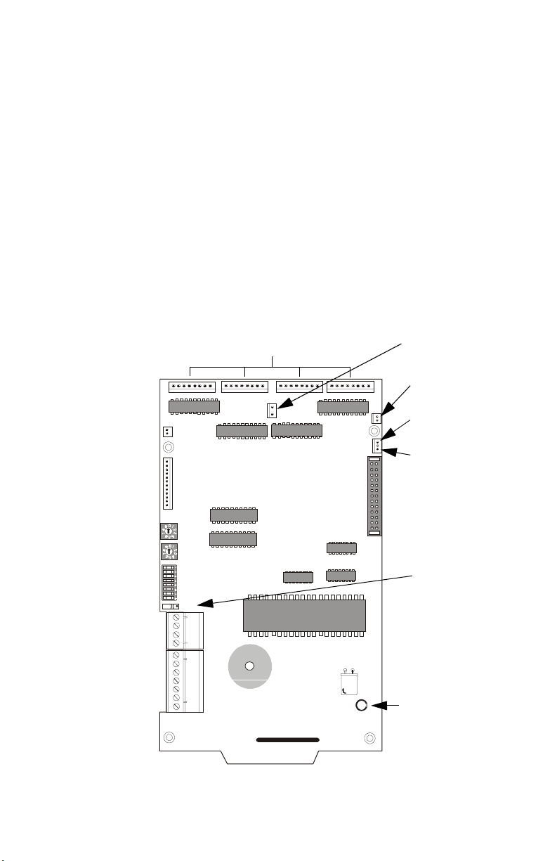
LDM-32F
The Lamp Driver Module LDM-32F has 32 alarm lamp/LED driver outputs
which sink current to system common (–) on activation. A single positive (+)
voltage is required to supply total operating power for all lamps or LEDs when
all drivers are activated. The LDM-32F provides a separate driver for system
trouble and inputs for a local lamp test switch. A maximum of 16 external
control switches may be wired to the LDM-32F. DIP switch SW3 is used to
enable or disable the onboard piezo, enable remote switch functions, select a
flashing LED function for new alarms and troubles, and other functions.
Switch SW4 is used to configure the module to annunciate 32 alarms or 16
troubles. A green
ON LINE
with the host FACP. One LDM-32F supports up to 3 LDM-E32F modules. The
LDM-32F is supplied with 4 standoffs and screws for mounting to a CHS-4L
chassis or custom backbox.
LED flashes to indicate ongoing communications
Output Connectors
for Wiring to LEDs
Lamp Power
(+5 VDC)
Security Key
Switch Terminal
Control Switch
Terminal
Address
Switches
Programming
DIP Switch
EIA-485
Terminal
24 VDC
Power
Terminal
J4
KEYSWITCH
SWITCH
MATRIX
J1
SW1
SW2
SW3
SW4
J5
4
3
2
1
7
6
5
4
3
2
1
J6 J7 J8
TB2
TB1
Figure 1 LDM-32F
Not Used
J11
LAMP
POWER
J10
J9
Lamp Power
(+24 VDC)
System Trouble
Ribbon Cable
Connection to
LDM-E32F
J2
Alarm or
Alarm/Trouble
Slide Switch
LDM-32F.cdr
ON LINE
Indicates EIA-485
Communication
Active
10
LDM-32F PN 50055:C 03/20/01
Page 11
Features 1. Introduction
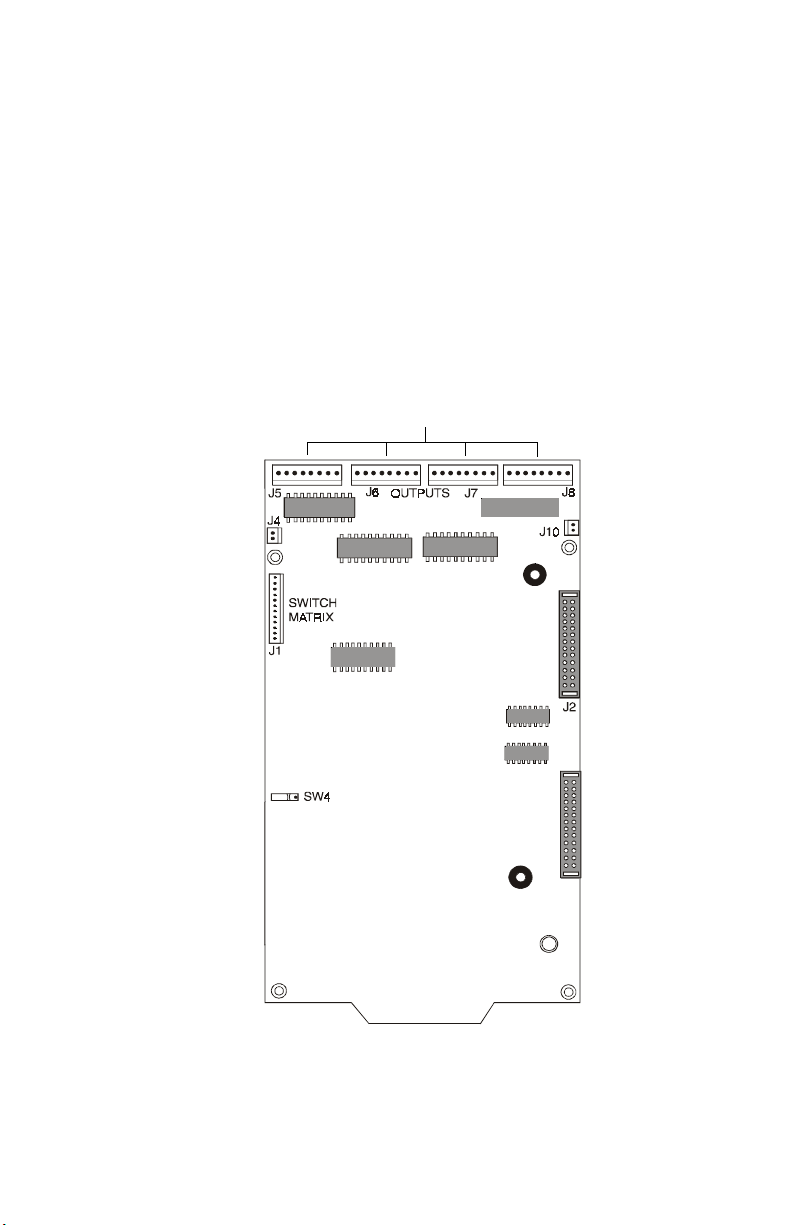
LDM-E32F
Each LDM-E32F expander module provides 32 additional lamp/LED driver
outputs from J5, J6, J7 and J8. The expander module has a slide switch SW4
for selecting alarm or alarm and trouble annunciation and an input for a local
lamp test switch. In alarm mode, use only one LDM-32F and one LDM-E32F
for a maximum of 56 alarm indicators and 8 system status indicators. In alarm/
trouble mode, use one LDM-32F and three LDM-E32Fs for a maximum of 56
alarm indicators, 56 trouble indicators, 16 status indicators and 64 optional
control switch inputs. Multiple sets of LDM-32Fs with LDM-E32F expanders
increase the system annunciation capabilities beyond 56 zones or points. This
is possible by various settings of address switches SW1 and SW2 on the LDM32F (refer to Appendices). Each LDM-E32F is supplied with a 26-conductor
expander ribbon cable, 4 standoffs and 4 screws.
Output Connectors
for Wiring to LEDs
Security Key
Switch Terminal
Control Switch
Te rm i n al
Alarm or
Alarm/Trouble
Slide Switch
Not Used
Ribbon Cable
Connections to
Next LDM-E32F
Ribbon Cable
Connections from
LDM-32F or
Previous LDM-E32F
LDM-E32F.cdr
Figure 2 LDM-E32F
LDM-32F PN 50055:C 03/20/01
11
Page 12

1. Introduction Features
Connectors
J1 - Switch Matrix
Up to 16 optional external control switches and a local lamp test switch may
be attached to the LDM-32F and LDM-E32F via J1 as shown in Figure 16 on
page 24. In the Sensiscan 2000, the control switches may be mapped to the CPU
function switches and all
9600, the switches may only be used for remote Acknowledge, Reset, Drill and
Silence. External switches must be momentary type.
J2 - Ribbon Cable Connection to J3
A single 26-conductor ribbon cable may be connected from J2 on the LDM32F or LDM-E32F (see Figure 6 on page 18) to J3 on adjacent LDM-E32Fs.
The ribbon cable carries power, ground and signaling from the master module
to up to three expander modules. The preformed cables are supplied in fixed
lengths of 24 and 48 inches.
J3 - Ribbon Cable Connection from J2
This connector supports a single 26-conductor ribbon cable from J2 of the
previous LDM-32F or LDM-E32F. Refer to Figure 6 on page 18.
J4 - Key Switch Input
This two pin connector is provided as an input on LDM-32F and LDM-E32F
modules for an external security key switch. Key switch contacts must be
Normally Closed. The key switch prevents unauthorized use of remote control
switches wired to J1.
J5, J6, J7 and J8 - Lamp/LED Driver Outputs
input and output modules. In the MS-9200 and MS-
Each connector provides 8 driver outputs for a total of 32 drivers on each LDM32F and LDM-E32F. Each driver is rated for a maximum of 30 volts and a
current of 100 mA. Each bipolar Darlington open collector driver output must
be current limited by an external resistor. 8-Point Shift and Flash functions are
selectable by DIP switch SW3 (refer to "SW3 - Function DIP Switch" on page
13). Lamp/LEDs may function in ‘alarm only’ mode or ‘alarm/trouble’ mode
as selected by switch SW4. Use the charts and examples shown in Appendices
for additional information.
J9 - 24 VDC Lamp Power/System Trouble
Connector J9 is located only on the LDM-32F. J9 pin 1 provides 24 volts
regulated power to all lamps/LEDs used in a custom graphic annunciator. The
current limit of J9 pin 1 is dependent upon the current limits of the external
power source being used. J9 pin 3 is a driver output for system trouble
indication only. J9 pin 2 connects to system common.
J10 - Relay Expander
Not used on the Sensiscan 2000, MS-9200 and MS-9600.
12
LDM-32F PN 50055:C 03/20/01
Page 13

Features 1. Introduction
J11 - 5 VDC Lamp Power
This connector is located only on the LDM-32F. J11 pin 1 provides 5 volts
regulated power to all lamps/LEDs used in a custom graphic annunciator. The
maximum current available from this output is 300 mA. This current is
sufficient to power the maximum number of LEDs available with one LDM32F and three LDM-E32Fs (from J5, J6, J7, J8 and one system trouble LED)
provided the
current rating per LED is 2 mA.
Switches
SW1 and SW2 - Address Switches
Two rotary BCD switches, located only on the LDM-32F, are used to set the
LDM Series system address. Switch SW1 represents the ‘ones’ position and
switch SW2 represents the ‘tens’ position of the address setting. In system
configurations of 56 zones or less, the switches must be set to address 01 for
all LDMs in the system. For configurations larger than 56 zones, multiple sets
of LDMs are required with sequential addresses, the first LDM starting at
address 01. Each incremental setting adds 64 zones/points to the system.
For example, an MS-9200 system requiring annunciation of alarms and
troubles for all 198 points would require four sets of LDMs with addresses 01,
02, 03 and 04. The MS-9600 is an exception (refer to "Appendix C: MS-9600"
on page 51 for information).
SW3 - Function DIP Switch
SW3, which is located only on the LDM-32F, is used to set the annunciator
functions. Function settings include:
• Number of expanders connected
• 8-Point Shift enabled
• Receive Only communications to host FACP
• Receive/Transmit communications to host FACP
• Control Switch disable
• Piezo disable
• Flash Inhibit
Refer to "Function DIP Switch - SW3" on page 25 for additional information.
SW4 - Alarm/Trouble Mode Switch
The Alarm/Trouble mode switch is installed on the LDM-32F and LDM-E32F.
The switch setting on each
expander module must match the switch setting of
the associated LDM-32F. ‘Alarm Only’ mode causes the driver outputs to turn
on only for alarm conditions per associated zone or point at the host FACP.
‘Alarm/Trouble’ mode causes the driver outputs to turn on for both alarm and
trouble conditions per associated zone or point at the host FACP. Since this
switch affects the assignments of connectors J5, J6, J7 and J8, make certain to
review the appendices in this manual for additional information on wiring to
the lamp/LED drivers.
LDM-32F PN 50055:C 03/20/01
13
Page 14

1. Introduction Features
Terminal Blocks
TB1 - 24 VDC Power, Earth Ground and Supervision
Removable terminal block TB1 appears only on the LDM-32F. 24 volts powerlimited, regulated, non-resettable power from the host FACP or a compatible
UL listed battery backed power supply must be connected to TB1(+) and TB1-
COMMON OUT
COMMON IN
(-) may be used to daisy chain the 24 volts to other LDMs or
devices. Earth ground must be connected to TB1and TB1-
N.C. SUPERVISION INPUT
(-). Terminals TB1-
provide a supervised input which may be
POWER OUT
EARTH
(+) and TB1-
. Terminals TB1-6
POWER IN
used to supervise local power sources or other devices. A trouble signal is
transmitted to the host FACP upon an open circuit across these terminals. The
input must be power-limited. If these terminals are not used, a jumper must
be installed.
TB2- EIA-485 In/Out
Removable terminal block TB2 appears only on the LDM-32F. All LDM-32Fs
must connect to the EIA-485 communications bus circuit for proper operation.
The EIA-485 bus carries commands and data sent between the host FACP and
the LDMs. The input must be power-limited.
Cables
Expander Ribbon Cable
The Expander Ribbon Cable (PN 75120) is supplied with the LDM-E32F to
allow for connection to the LDM-32F master module. The cable connects
between J2 of the LDM-32F or LDM-E32F and J3 of the next LDM-E32F.
The LDM-CBL24 and LDM-CBL48
Cable sets for connecting LDM-32F and LDM-E32F connectors to lamps/
LEDs, switches, etc., are provided through the optional LDM-CBL24 (24"
long) and LDM-CBL48 (48" long) cabling kits. Each cable has a plug on one
end for connection to the LDM modules.
Each LDM-CBL24 cable kit includes:
• (4) P/N 75116, 24" cable consisting of 8 stranded, multicolored
conductors. Cables connect to J5, J6, J7 and J8.
• (1) P/N 75122, 24" cable consisting of 10 stranded, multicolored
conductors. Connects to J1, optional control switches.
• (1) P/N 75117, 24" cable consisting of 2 stranded, single color
conductors. Connects to
J1, Lamp Test Switch.
• (1) P/N 75118, 24" cable consisting of 3 stranded, multicolored
conductors. Connects to J9 or J11, Lamp Power.
14
LDM-32F PN 50055:C 03/20/01
Page 15
Related Documentation 1. Introduction
Each LDM-CBL48 cable kit includes:
• (4) P/N 75147, 48" cable consisting of 8 stranded, multicolored
conductors. Cables connect to J5, J6, J7 and J8.
• (1) P/N 75150, 48" cable consisting of 10 stranded, multicolored
conductors. Connects to J1, optional control switches.
• (1) P/N 75148, 48" cable consisting of 2 stranded, single color
conductors. Connects to J1, Lamp Test Switch
.
• (1) P/N 75149, 48" cable consisting of 3 stranded, multicolored
conductors. Connects to J9 or J11, Lamp Power.
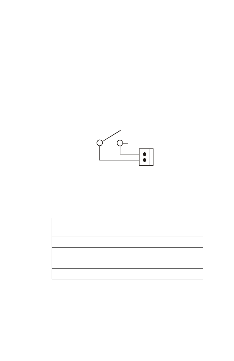
Key-lock Control Switch Security
A UL listed key-lock switch wired to J4 on the LDM-32F should be used to
provide access security for all control switches wired to that set of LDM
modules.
Note: Control switches will not function when the key-lock switch is in its closed position.
J4
2
Key Switch
Figure 3 Key-lock Switch Wiring Diagram
LDM-32F
1
LDM32F-keysw.cdr
Related Documentation
Further details about products referenced in this document can be found in the
manuals for the particular fire alarm control panel and components.
Product
MS-9200 Fire Alarm Control Panel Instruction Manual 51003
MS-9600 Fire Alarm Control Panel Instruction Manual 51335
Sensiscan 2000 Fire Alarm Control Panel Instruction Manual 15017
CAB-3F Series Cabinets Installation Document 15391
LDM-32F PN 50055:C 03/20/01
Part
Number
15
Page 16

1. Introduction Related Documentation
NOTES
16
LDM-32F PN 50055:C 03/20/01
Page 17
2. Installation
External Cabinets
The CAB-A3F and the CAB-B3F are UL listed cabinets suitable for use in
graphic annunciator applications. For size and dimensions, refer to the CAB3F Series Installation Document.
Select and remove the appropriate knockout(s) on the cabinet.
Securely mount the cabinet.
Ground the cabinet to a solid electrical ground per NEC Article 250.
Pull all wiring into the cabinet. (Refer to the appropriate FACP manual for UL
Power-limited Wiring Requirements.)
Note: Other cabinets such as those provided by custom graphic annunciator
manufacturers may be used provided they meet UL requirements as UL listed secured
enclosures.
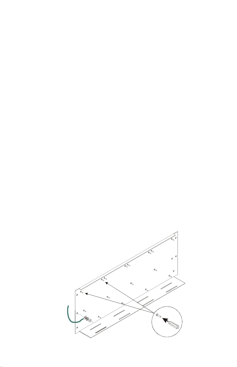
CHS-4L Chassis
The CHS-4L chassis will support one LDM-32F module and up to three LDME32F expander modules. The chassis is mounted inside the CAB-A3F or the
CAB-B3F cabinet.
Mount the CHS-4L Chassis to a cabinet and secure with the hardware provided.
The Grounding Cable must be connected to the chassis mounting stud for
connection to the annunciator's earth ground terminal for proper operation as
well as to aid in transient protection. For each LDM module to be installed on
the chassis, connect two female-to-female standoffs (provided) to the upper
mounting studs on the chassis.
LDM-32F PN 50055:C 03/20/01
LDM32-chs4l.cdr
Figure 4 CHS-4L Mounting
17
Page 18
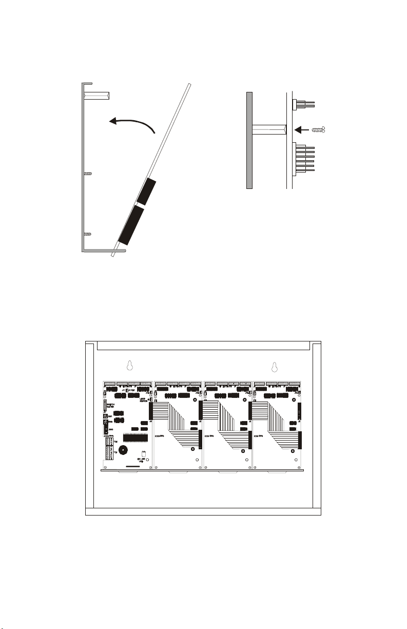
2. Installation CHS-4L Chassis
Slip the bottom edge of the module or expander board into the slot on the chassis
and move the module toward the standoffs. Secure the board to the standoffs
with the screws provided. Repeat for installation of additional modules or
expanders.
Ldminchs.cdr
Figure 5 Installing LDM Modules in CHS-4L
Connect an expander ribbon cable (P/N 75120) from the LDM-32F connector
J2 to J3 of the first LDM-E32F expander module. If multiple LDM-E32F
modules are to be used, connect additional cables from J2 to J3 as shown below.
One LDM-32F may support a maximum of three LDM-E32F modules.
18
Expander Ribbon Cables
LDM-32F LDM-E32F LDM-E32F LDM-E32F
Ldmincab.cdr
Figure 6 LDMs Mounted in UL Listed Cabinet
LDM-32F PN 50055:C 03/20/01
Page 19
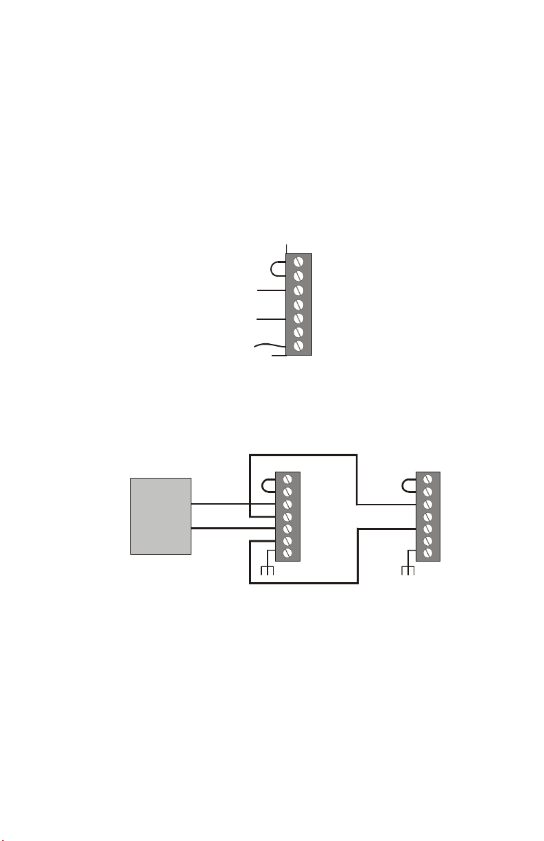
Wiring the Power Terminal Block 2. Installation
Wiring the Power Terminal Block
24 VDC Power and Earth Ground
24 VDC power supplied to the LDM must be power-limited. This power is
inherently supervised (loss of power also results in a communication failure at
the control panel).
• Limit the total wire resistance to 10 ohms.
• Connect the Grounding Cable from the chassis to the earth ground
terminal of TB1 (
• Connect 24 VDC power to the
terminals of TB1.
24 VDC
Power
Grounding Cable
Figure 7 24 VDC Power Terminals - TB1
EARTH
).
POWER IN
TB1
(+) and
N.C. Supervision
Inputs
Common In (–)
Common Out (–)
Power In (+24 VDC)
Power Out (+24 VDC)
Earth
COMMON IN
(–)
LDM32F-TB1.cdr
Wiring of multiple LDM-32F modules.
Host FACP or Remote
Power Supply
– 24 VDC
+ 24 VDC
Figure 8 Multiple Module Wiring - 24 VDC
LDM-32F PN 50055:C 03/20/01
First LDM-32F -- -- -- -- -- -- -- Last LDM-32F
TB1 TB1
LDM32F-power.cdr
19
Page 20
2. Installation Wiring the EIA-485 Terminal Block
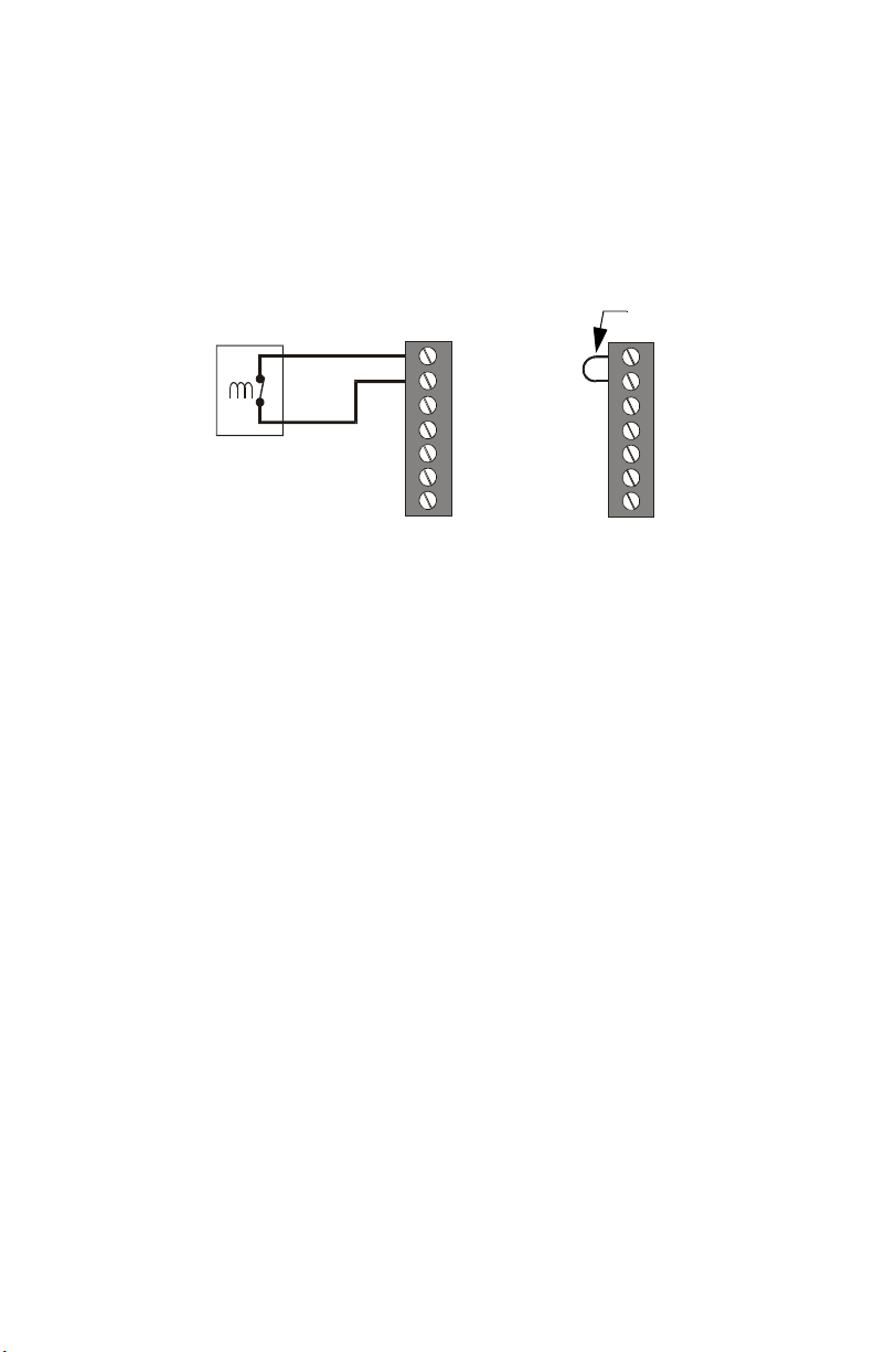
Supervision Input
The Supervision Input, which requires a normally-closed condition, can be
used for supervising power sources or ot her devices. It must be power-limited.
If employed, a change in status will be transmitted to the host control panel in
the event of device failure or restoral.
If not used, a jumper must be installed across these terminals on TB1. A trouble
signal will be registered by the control panel if a short circuit does not exist
across terminals 6 & 7.
Device to be
Supervised
Supervision
Inputs
(5 VDC @
0.5 mA)
Normally Closed
Trouble Contacts
Jumper
TB1
Figure 9 Wiring Supervision Terminals
TB1
Wiring the EIA-485 Terminal Block
A maximum of 32 LDM-32Fs may be connected to the EIA-485 bus, but if
other types of devices are also connected to this bus, the maximum number
of LDM-32Fs must be reduced by the total of such devices. Total annunciation
and switch capability depends upon the number of expander modules used.
Communications between the Fire Alarm Control Panel and the LDM-32F is
accomplished over a two-wire EIA-485 serial communications bus which must
be power-limited. Communications between the host FACP and LDMs is
supervised by the fire alarm control panel.
Wiring Specifications
• The EIA-485 circuit cannot be T-tapped; it must be wired in a
continuous fashion from the control panel to the LDMs.
• The maximum wiring distance between the panel and LDMs is 6000
feet.
• The wiring must be a 18 AWG to 14 AWG twisted shielded pair cable
having a characteristic impedance of 120 ohms, +/- 20%.
• Limit the total wire resistance to 100 ohms.
• Do not run cable adjacent to, or in the same conduit as, 120 volts AC
service, noisy electrical circuits that are powering mechanical bells or
horns, audio circuits above 25 V
power circuits.
Note: Never use the shield for grounding purposes. Terminate the EIA-485 shield at the
Fire Alarm Control Panel only.
20
, motor control circuits, or SCR
RMS
LDM-32F PN 50055:C 03/20/01
LDM32F-super.cdr
Page 21

Wiring the EIA-485 Terminal Block 2. Installation
Wire Chart
Standard Annealed Copper Wire
Wire Size
A.W.G
14 64 4110 0.00323 2.85 2.97 12.4
16 51 2580 0.00203 4.09 4.73 7.82
18 40 1620 0.00128 6.51 7.51 4.92
Diameter
in Mils
Cross Section Ohms per 1000 feet
Circ. Mils Sq. Inch @ 77°F. @ 149°F.
Pounds per
1000 feet
Table 1 Wire Specifications
EIA-485 Shield in Conduit
When the EIA-485 wiring is in conduit, connect the shield to system common.
The shield can enter the cabinet, but must be insulated from the cabinet (no
electrical contact). Between LDMs, wire-nut multiple shields together (which
can be inside of the respective LDM enclosure but ensure that the shield does
not contact earth ground).
TB2
–
–
+
+
LDM32F-term1.cdr
Figure 10 Terminating the Shield in Conduit
EIA-485 Shield Not in Conduit
When the EIA-485 wiring is not in conduit, terminate the shield at the outside
of the FACP cabinet. Do not allow the shield to enter or even touch the cabinet
housing the LDMs. Between LDMs, wire-nut multiple shields toget her outside
of the respective enclosures. Ensure that the shield does not touch earth ground
at any junction points.
TB2
–
–
+
+
Figure 11 Terminating the Shield with No Conduit
LDM-32F PN 50055:C 03/20/01
LDM32F-term2.cdr
21
Page 22

2. Installation Wiring the EIA-485 Terminal Block
EIA-485 - TB2 Terminals
Wire as shown below.
Note: Leave a 120 ohm ELR installed across the EIA-485 Out terminals at the last LDM32F on the circuit (see below). All other LDM-32Fs should not have a resistor installed.
TB2
In (–)
Out (–)
Out (+)
In (+)
LDM32F-TB2.cdr
Figure 12 EIA-485 Terminal Block - TB2
Multiple wiring of EIA-485 circuits.
First LDM-32F -- -- -- -- -- -- Last LDM-32F
Host FACP
Host FACP
TB2 TB2
EIA-485 (–)
ELR
EIA-485 (+)
LDM32F-mult.cdr
Figure 13 Wiring Multiple LDM-32Fs - EIA-485
22
LDM-32F PN 50055:C 03/20/01
Page 23

Wiring for Lamp/LED 2. Installation
Wiring for Lamp/LED
• All LEDs must be located in the same room as the LDM modules.
• For 5 volt output use a 680 ohm, 1/4-watt resistors for each point if
using 2 mA LEDs.
• For 24 volt output use a 10K ohm, 1/4-watt resistors for each point if
using 2 mA LEDs.
• LEDs: use red for alarm points, yellow for trouble points and green
for output points.
• Use the cables supplied in the cable kit to wire connectors on LDM.
The figure below illustrates LEDs being powered by the 5 volt output from
LDM-32F, J11 pin 1.
Custom Graphic Display Wiring is not
supervised
Point Status LEDs
System
Trouble
LED
Resistor
J5 J6 J7 J8
1234567
8
9101112131415
16
J11
LDM-32F
171819202122232425262728293031
LAMP
POWER
32
J10
J9
Figure 14 Typical LDM-to-Graphics Display Connection @ 5VDC
The figure below illustrates LEDs being powered by the 24 volt output from
LDM-32F, J9 pin 3.
Custom Graphic Display
Point Status LEDs
Resistor
J5 J6 J7 J8
1234567
8
9101112131415
16
J11
LDM-32F
171819202122232425262728293031
LAMP
POWER
32
J10
J9
Figure 15 Typical LDM-to-Graphics Display Connection @ 24VDC
Wiring is not
supervised
System
Trouble
LED
LDM32F-5voltout.cdr
LDM32F-24voltout.cdr
LDM-32F PN 50055:C 03/20/01
23
Page 24

2. Installation Wiring the Control Switch
Wiring the Control Switch
Each LDM must be set for Alarm/Trouble mode by positioning slide switch
SW4 to the right, for the optional control switches to function (the
acknowledge/lamp test switch will work in either mode). In this configuration,
each LDM-32F and LDM-E32F provides 16 alarm drivers, 16 trouble drivers
and 16 control switches. The alarm and trouble drivers are assigned to host
FACP zones/points via user setup. Not all switches must be used - switches can
be wired only for desired functions.
• Switches must be UL listed to switch 5 volts DC @ 0.5mA.
• Switches must be key-lock type, secured in a locked enclosure or a
security key switch must be installed to control access.
• All switches must be installed in the same room as, and no more than
20 feet from, the LDM enclosure. Wiring must be in conduit.
• Optional zone/point control switches must be momentary type.
• Use the cables supplied in the cable kit to wire the control switches.
• See Appendices for specific FACP information.
Switch #16
Switch #15
Switch #14
Switch #13
Switch #12
Switch #11
Switch #10
Switch #9
Lamp Test/Acknowledge
Switch (momentary)
J5
J4
24
Switch #8
Switch #7
Switch #6
Switch #5
Switch #4
Switch #3
Switch #2
Switch #1
Manual Evacuate
System Reset
Signal Silence
Acknowledge
Note: Switches 5 - 16 are not used in this example.
Figure 16 Optional Zone/Point Control Switch Wiring
J1
SWITCH
MATRIX
SW1
SW2
12345
SW3
6
78
SW4
Ldmswtwr.cdr
LDM-32F PN 50055:C 03/20/01
Page 25

Configuring the LDMs 2. Installation
Configuring the LDMs
Address Switches - SW1 and SW2
It is critical to the operation of the LDMs that the Address Switches be set
correctly.
To set the LDM-32F’s address to ‘01’, position the arrow on SW2 (tens) so it
points to 0 and position the arrow on SW1 (ones) so it points to 1.
SW2 SW1
LDM32F-SW1-2
Figure 17 Address Switches SW1 & SW2
Function DIP Switch - SW3
These switches are used to determine how the LDM-32F operates. The
following illustration provides details on DIP switch placement in the On and
Off position:
Side View of Switch
Shown in the OFF
Position
O
F
F
OFF
1
2
345
678
LDM32F-SW3.cdr
Figure 18 Function DIP Switch
LDM-32F PN 50055:C 03/20/01
25
Page 26

2. Installation Configuring the LDMs
Switch Settings
1 - Not Used: This switch must be set “OFF”
2 - Expanders Installed: None = OFF; One = ON; Two = OFF; Three = ON
3 - Expanders Installed: None = OFF; One = OFF; Two = ON; Three = ON
4 - Eight-Point Shift: Set switch “ON” to switch the FACP LED function
annuciation from the first eight annunciator positions on the LDM-32F to the
last LDM-E32F expander positions 57 - 64. This shift can only be set on an
LDM-32F set for address 01 (system using 56, or less, software zones).
5 - Receive Only: Set this switch “ON” for each LDM series that will provide
the same information as another LDM series in a different physical location.
Note: When two or more LDM series hold the same address, all but one must be
configured as “Receive Only”.
6 - Piezo Disable: Set this switch “ON” to disable the piezo from sounding for
any event. (The piezo will also be disabled if Flash Inhibit is “ON”.)
7 - Switch Inhibit: To disable the point control switches on the LDMs from
functioning, set this switch “ON”. When inhibited, the local lamp test switch
continues to function. In addition, the acknowledge/lamp test switch will
function only in a local capacity, unrecognized by the host FACP.
8 - Flash Inhibit: Set this switch “ON” to disable the flashing of LEDs
associated with unacknowledged events. Flash Inhibit also disables the piezo
from sounding.
Mode Switch - SW4
Set the mode of operation to:
“Alarm/Trouble” by sliding the switch to the right
“Alarm Only” mode by sliding the switch to the left.
Alarm Only
Mode
Figure 19 Mode Select Switch - SW4
26
Alarm/Trouble
Mode
LDM32F-SW4.cdr
LDM-32F PN 50055:C 03/20/01
Page 27

3. Operation
Lamp Test/Acknowledge
A separate, dedicated lamp test switch is required for each LDM-32F and
LDM-E32F (see "Wiring the Control Switch" on page 24). A switch installed
for LAMP TEST/ACKNOWLEDGE performs two functions:
1. When pressed, it will light all LEDs wired to the specific LDM module
(except the On Line LED) and will sound the integral piezo (if enabled)
for as long as the switch is held down. The Lamp Test switch will light
only the LEDs on the module to which it is wired.
2. The switch connected to the LDM-32F, when pressed, acknowledges all
status changes (for both the LDM-32F and any LDM-E32F expanders).
Flashing LEDs will latch on solid and the piezo will be silenced.
On Line LED
This green LED, located on the LDM-32F module (see Figure 1 on page 10),
flashes during communication with the host control panel.
Graphic Annunciator Lamps/LEDs
To adhere to standard fire alarm control panel convention and remain
consistent with other products that may exist in the system, the following color
convention is employed:
Red Alarm LEDs - To indicate an alarm condition for an Initiating Device
Circuit or a software zone.
Yellow Trouble LEDs - To indicate a trouble condition exists on an
initiating or indicating device circuit or zone. Yellow trouble LEDs also are
used to indicate general system trouble conditions such as low battery, earth
fault, general system trouble, etc.
Green Controlled Output LEDs - Indicates that power is applied or that
the controlled output circuit or device has been activated. Applicable to
notification appliance, relay, speaker, telephone, and time control circuits.
Note: The graphic annunciator may contain a yellow System Trouble LED and a red
System Alarm LED which will light for all trouble or alarm conditions (respectively) in the
system (not just for those points of zones mapped to the LDM master/expanders).
LDM-32F PN 50055:C 03/20/01
27
Page 28

3. Operation Graphic Annunciator Lamps/LEDs
NOTES
28
LDM-32F PN 50055:C 03/20/01
Page 29

4. LDM Communications
Receive Only LDM-32Fs
For duplicate annunciation of system points, LDMs can be configured for
Receive Only annunciation. Receive Only LDMs must be set to the same
address as the LDM they duplicate, but are not fully supervisable. Receive
Only LDMs intercept information being transmitted to a Receive/Transmit
LDM so that this information can be duplicated at an intermediate display
location. When configured for Receive Only operation, LDMs cannot transmit
information to the host control panel. Remote Acknowledge, Silence, or Reset
cannot be performed. Control switches on Receive Only LDMs are for local
lamp test only. If a Receive/Transmit LDM is located at the end of the EIA485 bus, it will provide supervision of Receive Only LDMs located on the EIA485 bus between the Receive/Transmit LDM and the FACP.
Receive/Transmit LDM-32F
LDMs that are configured to serve as full-function annunciators can both
receive status information for annunciation as well as transmit commands to
the control panel through custom-wired point control switches. This allows the
LDM to initiate control panel switch functions from a remote location in
addition to displaying the status of the system. In order for wiring connecting
all Receive/Transmit LDMs to be supervised, the LDM-32F addressed as '01'
must be placed at the end of the EIA-485 loop farthest from the FACP. Only
address '01' is supervised.
Receive Only LDM-32F
Fire Alarm Control Panel
Set to Address X
LDM-32F PN 50055:C 03/20/01
EIA-485 Circuit
LDM-32F LDM-E32F
Receive/Transmit LDM-32F
Set to Address X
LDM-32F LDM-E32F
Figure 20 LDM-32F Supervision
Ldmsupv.cdr
29
Page 30

4. LDM Communications Receive/Transmit LDM-32F
NOTES
30
LDM-32F PN 50055:C 03/20/01
Page 31

5. Electrical Ratings and Current Calculations
Lamp Driver Electrical Ratings
LDM modules may use either 24 VDC (regulated) or internal 5 VDC for
powering connected LEDs. 5 volt usage conserves power but is limited in the
current available to drive the LEDs. Refer to "Wiring for Lamp/LED" on page
23 for connection illustrations.
5 Volt LED Power Limitations
LED Current
Desired (mA)
2 13013
56611
10 34 1 0
Note: The LDM-32F drives 32 LEDs and each LDM-E32F drives 32 more LEDs. An LDM
system configured for Alarm and Trouble Display Mode and employing three expanders
could have as many as 128 LEDs, all of which are activated during Lamp Test.
Max Number
of LEDs
Table 2 Power Limitations
Number of Modules
LDM-32F LDM-E32F
Maximum Current per Driver: 100 mA (external circuit must limit current)
Maximum Voltage rating per output driver: 30 VDC
Supervised circuit (typical rating): 5 volts DC @ 0.5 mA
Bipolar Darlington Open Collector NPN Transistor
Supervision of LDM points
Any LEDs or lamps connected to the LDM-32F or LDM-E32F are not
supervised for failure. Therefore, all LEDs or lamps, must be located in the
same room as the LDM modules.
LDM-32F PN 50055:C 03/20/01
31
Page 32

5. Electrical Ratings and Current Calculations Calculating Standby and
Calculating Standby and Alarm Currents
The LDM series annunciators draw their power from the Fire Alarm Control
Panel and must be considered when calculating primary and secondary power
requirements. Refer to the installation manual for the particular control panel
employed for the calculation of power requirements for the entire system.
1. Enter Standby Total obtained here into the standby calculation tables of
the installation manual.
2. Enter Alarm Current Total obtained here into the alarm calculation tables
of the installation manual.
Standby Current
Numb er of LDM-32F Modules [ ]
Number of LDM-E32F Expanders [ ] X 2 mA =
Standby Total = [ ] amps
Alarm Current
Numb er of LDM-32F Modules [ ] X 56 mA =
Numb er of LDM-E32F Expander [ ] X 18 mA =
Number of LEDs
Number of LEDs
1. The 0.040 amps can be reduced to 0.030 for modules with Piezo disable or Flash Inhibit selected.
2. Use this line for calculations if LEDs are powered from 24 VDC source.
3. Use this line for calculations if LEDs are powered from the 5 VDC source from J1 on the LDM-32F.
2
3
[ ] X [ ]mA per LED=
[ ] X [( )mA/3]=
Alarm Current Total = [ ] amps
X 40 mA
1
=
Table 3 Power Requirement Calculations
32
LDM-32F PN 50055:C 03/20/01
Page 33

Appendix A: Sensiscan 2000
Capabilities
When installed with a Sensiscan 2000, the LDM Series modules can annunciate
general system status; the status of all initiating and notification circuits and
output relays. Plus, manually activate all points via control switches. Each
lamp driver output may be assigned to one and only one system I/O point:
Optional Sensiscan 2000 plug in Modules -
IZ-8F - Initiating Device Circuits (alarm and trouble)
IZ-4F/IZE-AF - Initiating Device Circuits (alarm and trouble)
IC-4F/IC-4CCF - Notification Appliance Circuits (trouble)
ICE-4F - Notification Appliance Circuits (trouble)
CR-4F/CRE-4F - Control Relay Modules
TC-2F/TC-4F - Time Control Modules
Sensiscan 2000 modules are user configurable. Refer to the Sensiscan 2000
Manual.
System Control Switches -
Acknowledge
Signal Silence
System Reset
Activate selected system outputs (notification circuits, relays)
System Control Switches on the Sensiscan 2000 CPU may be remoted via the
LDM series modules. Also, zone/point control switches may be configured.
Trouble Indication
Communication between the CPU and the LDMs is accomplished over a twowire EIA-485 serial communication bus. The EIA-485 bus is supervised by
the Sensiscan 2000. Loss of communication results in System Trouble and
Module Failure indications at the CPU.
Programming and Testing the LDM-32F
After complete installation, the Lamp Driver Module(s) must be programmed
into the control panel as if it were an annunciator. After programming the fire
alarm control panel to accept them, fully test the LDM(s) by ensuring that each
switch and LED performs its intended function, and that the LDM(s) can
perform the functions outlined in "3. Operation" on page 27.
LDM-32F PN 50055:C 03/20/01
33
Page 34

Appendix A: Sensiscan 2000 Power Supply Connection
Power Supply Connection
The LDMs may be powered by an MPS-24AF or an MPS-24BF. The power
run to the LDMs need not contain a Power Supervision Relay since loss of
power is inherently supervised.
MPS-24AF Main Power Supply
Connect the power run for the LDMs to MPS-24AF TB3, Terminals 1 (+)
and 2 (–). Maximum current is 1 amp.
To LDM-32F TB1
Power In (+)
+24R COMMON +24 COMMON
BAT + BAT -
TB2
Figure 21 MPS-24AF Power Supply Connections
MPS-24BF Main Power Supply
Connect the power run for the LDMs to MPS-24BF TB2, Terminals 1 (+)
and 2 (–). No more than 200 mA current can be drawn from these terminals
in standby or alarm.
To LDM-32F TB1
Power In (+)
To LDM-32F TB1
Common In (–)
POWER L IMI TED
P3
To LDM-32F TB1
Common In (–)
P2
P5
P4
R27
LDM32F-mps24af.cdr
6 7 8
TB2
+24 VRESET +24 VPOWER
1 2 3 4
BATT +
1 2
BATT -
TB3
P3
COMMON COMMON
Figure 22 MPS-24BF Power Supply Connections
EIA-485 Connection
The EIA-485 bus that communicates with the LDM must be connected to the
CPU as illustrated below.
Note: The CPU must be Revision D or greater. (The revision level of the CPU is marked
on a label affixed to the upper board.)
EIA-485
To TB 2 I n ( – )
Sensiscan 2000 CPU
Figure 23 EIA-485 Connection to CPU
34
EIA-485
To TB2 I n ( + )
LDM-32F PN 50055:C 03/20/01
LDM32F-mps24bf.cdr
LDM32F-s2000.cdr
Page 35

Lamp/LED Driver Operation Appendix A: Sensiscan 2000
Lamp/LED Driver Operation
LDM Address Switches (SW1 & SW2) must be set to address ‘01’.
Lamp Driver outputs do not latch - they track or follow the status of each zone/
point that they are assigned to annunciate. The table below defines the ON
status of each lamp driver output.
Note: Control Switches marked 'Not Used' will still function as local LAMP TEST or local
ACKNOWLEDGE switches for their respective points.
Note: If Alarm Only mode is selected, column labeled Yellow LED is not applicable and
control switches do not function.
CPU Points
1
Annunciator
Point #1
Annunciator
Point #2
Annunciator
Point #3
Annunciator
Point #4
Annunciator
Point #5
Annunciator
Point #6
Annunciator
Point #7
Annunciator
Point #8
1. If the 8-Point Shift (DIP switch #4 of SW3) is set ON, the eight Sensiscan 2000 CPU
functions (ACK, SIL, RESET, LAMP TEST, NAC1, NAC2, MUNTIE, RELAY) will be
shifted from annunciator points 1 through 8 (as shown above) to points 57 through 64
(provided those points exist in the system and the LDM-32F is set to address 01).
2. Optional control switches are active only if all of these conditions are met:
a) '8-Point Shift' (DIP switch #4) is set to OFF.
b) Receive Only (DIP Switch #5) is set to OFF.
c) Switch Inhibit (DIP Switch #7) is set to OFF.
3. Use green LEDs to indicate activation on controlled output circuits.
Alarm
(Red LED)
System Alarm System Trouble Acknowledge
Not Used Signal Silence Signal Silence
Not Used Not Used System Reset
Not Used
NAC #1 Activated
NAC #2 Activated
Remote Signaling
of Municipal Tie
Activated
3
Alarm Relay
Activated
3
Trouble/Supv
(Yellow LED)
Supervisory
Condition
Trouble Status of
3
Circuit
Trouble Status of
3
Circuit
Trouble Status of
Circuit
Module Trouble,
Power Failure, or
Disabled Circuit
Control Switches
Not Used
NAC #1
NAC #2
Remote Signaling
of Municipal Tie
Alarm Relay
Table 4 Annunciator Point Assignment to LDMs
2
LDM-32F PN 50055:C 03/20/01
35
Page 36

Appendix A: Sensiscan 2000 Lamp/LED Driver Operation
The following table defines the point assignments if incorporating the optional
modules available on the Sensiscan 2000.
Optional
Modules
IZ-8F Alarm Status per
IZ-4F/IZE-4F Alarm Status per
IC-4F/IC-4CCF
ICE-4F
CR-4F/CE-4F Indicates
TC-2F/TC-4F Indicates
1. Optional control switches are active only if all of these conditions are met:
a) '8-Point Shift' (DIP switch #4) is set to OFF.
b) Receive Only (DIP Switch #5) is set to OFF.
c) Switch Inhibit (DIP Switch #7) is set to OFF.
2. These Status LEDs are active only when the Sensiscan 2000 is programmed for Output
Status. Use green LEDs to indicate activation on controlled output circuits.
3. These control switches require that the Sensiscan 2000 be programmed for Output Control.
Alarm
(Red LED)
Circuit
Circuit
Indicates
Activation
Indicates
Activation
Activation
Activation
Trouble/Supv
(Yellow LED)
Trouble Status per
Circuit
Trouble Status per
Circuit
2
2
2
2
Indicates Trouble
per Circuit
Indicates Trouble
per Circuit
Indicates Trouble
per Circuit
Indicates Trouble
per Circuit
Control Switches
Not Used
Not Used
Momentarily Turns
On NAC Output
When Pressed
Momentarily Turns
On NAC Output
When Pressed
3
Relays
Remote Switch
Functions
1
3
3
3
Table 5 Optional Modules Annunciator Point Assignment to LDMs
36
LDM-32F PN 50055:C 03/20/01
Page 37

Lamp/LED Driver Operation Appendix A: Sensiscan 2000
Alarm Only Operation
The table below illustrates the configuration of the LDM Series modules to
annunciate alarms for up to 56 zones/points (no troubles) with the first eight
points (P1 through P8) dedicated to the Sensiscan 2000 system status
annunciation (see Figure 24 below).
Note: Control switches do not function in Alarm Only configuration.
Note: The Address switch sets the limit of annunciator points per LDM series. With the
address set to 01, the limit is 64 annunciated points.
LDM Module
Address ‘01’
LDM-32F System Status 1 to 8 9 to 16 17 to 24
LDM-E32F 25 to 32 33 to 40 41 to 48 49 to 56
J5 J6 J7 J8
LDM Output Connectors
Table 6 Alarm Only Operation
Alarm Only Operation with 8-Point Shift
The table below illustrates the configuration of the LDM Series modules to
annunciate alarms for up to 56 zones/points (no troubles) with the last eight
points (P57 through P64) dedicated to the Sensiscan 2000 system status
annunciation (see Figure 24 below).
It is assumed that the ‘8-Point Shi ft’ will be selected only on systems containing
56 zones/points or less, or a total of 64 annunciator points or less.
Note: Control Switches do not function in Alarm Only mode.
Note: Addres s switch sets the limit of annunciator points per LDM series. With the address
set to 01, the limit is 64 annunciated points.
LDM Module
Address ‘01’
LDM-32F 1 to 8 9 to 16 17 to 24 25 to 32
LDM-E32F 33 to 40 41 to 48 49 to 56 System Status
J5 J6 J7 J8
LDM Output Connectors
System Status Indicators
NAC #1 ON (Green LED)
System Alarm (Red LED)
Figure 24 System Functions to Output Connectors - 1
LDM-32F PN 50055:C 03/20/01
Table 7 Alarm Only Operation with Shift
NAC #2 ON (Green LED)
Not
Used
Municipal Tie ON (Red
LED)
J5
1234567
J8
25262728293031
8
32
LDM32F-J5.cdr
37
Page 38

Appendix A: Sensiscan 2000 Lamp/LED Driver Operation
Alarm/Trouble Operation
The table below (also see Figure 25 on page 39) illustrates the configuration
of the LDM Series modules to annunciate alarms and troubles for up to 56
zones/points with the first eight points - 16 LEDs (J5: P1 through P8 and J6:
P1 through P8) dedicated to Sensiscan 2000 system status annunciation (see
Figure 26 on page 39).
LDM Module
Address ‘01’
LDM-32F System Status 1 to 4 5 to 8
1st LDM-E32F 9 to 12 13 to 16 17 to 20 21 to 24
2nd LDM-E32F 25 to 28 29 to 32 33 to 36 37 to 40
3rd LDM-E32F 41 to 44 45 to 48 49 to 52 53 to 56
J5 J6 J7 J8
LDM Output Connectors
Table 8 Alarm/Trouble Operation
Alarm/Trouble Operation with 8-Point Shift
The table below (also see Figure 25 on page 39) illustrates the configuration
of the LDM Series modules to annunciate alarms and troubles for up to 56
zones/points with the last eight points - 16 LEDs (J7: P1 through P8 and J8:
P1 through P8) dedicated to Sensiscan 2000 system status annunciation (see
Figure 27 on page 39).
LDM Module
Address ‘01’
LDM-32F 1 to 4 5 to 8 9 to 12 13 to 16
1st LDM-E32F 17 to 20 21 to 24 25 to 28 29 to 32
2nd LDM-E32F 33 to 36 37 to 40 41 to 44 45 to 48
3rd LDM-E32F 49 to 52 53 to 56 System Status
J5 J6 J7 J8
Table 9 Alarm/Trouble Operation
LDM Output Connectors
38
LDM-32F PN 50055:C 03/20/01
Page 39

Lamp/LED Driver Operation Appendix A: Sensiscan 2000
The figure below is an example of the connections used when setting the LDM
module for Alarm/Trouble mode.
Alarm - First 4 Zones or Points
Trouble - First 4 Zones or Points
Alarm - Second 4 Zones or Points
Trouble - Second 4 Zones or Points
Alarm - Third 4 Zones or Points
Trouble - Third 4 Zones or Points
Alarm - Fourth 4 Zones or Points
Trouble - Fourth 4 Zones or Points
J5 J6 J7 J8
1234567
8
9101112131415
16
171819202122232425262728293031
32
LCM32F-conn.cdr
Figure 25 Connections for Alarm/Trouble
The figure below illustrates pin usage of output connectors for system functions
in Alarm/Trouble mode.
System Status Indicators
Supervisory (Yellow)
Not Used
Signals Silenced (Yellow)
System Trouble (Yellow)
System Alarm (Red)
Not
Used
NAC #1 ON (Green)
NAC #2 ON (Green)
Municipal Tie ON (Red)
Alarm Relay ON (Red)
NAC #1 Trbl (Yellow)
NAC #2 Trbl (Yellow)
Municipal Tie Trbl (Yellow)
Alarm Relay Trbl (Yellow)
J5 J6
1234567
8
9101112131415
16
LCM32F-J5J6.cdr
Figure 26 System Functions to Output Connectors - 1
The figure below illustrates pin usage of output connectors for system functions
in alarm/trouble mode with 8-Point shift selected.
System Status Indicators
Supervisory (Yellow)
Signals Silenced (Yellow)
System Trouble (Yellow)
System Alarm (Red)
Figure 27 System Functions to Output Connectors - 2
LDM-32F PN 50055:C 03/20/01
Not Used
J7 J8
Not
Used
17181820212223
24
25262728293031
NAC #1 ON (Green)
NAC #2 ON (Green)
Municipal Tie ON (Red)
Alarm Relay ON (Red)
NAC #1 Trbl (Yellow)
NAC #2 Trbl (Yellow)
Municipal Tie Trbl (Yellow)
Alarm Relay Trbl (Yellow)
32
LCM32F-J7J8.cdr
39
Page 40

Appendix A: Sensiscan 2000 Control Switch Operation
Control Switch Operation
Circuit corresponds to a specific I/O module installed in user configured
Sensiscan 2000.
The first 8 control switches of the LDM-32F will correspond to CPU switch
functions as shown below, if “8-Point Shift” is not selected.
With “8-Point Shift” selected, the first 8 control switches move to the 3rd LDME32F and are assigned to Circuits 57 through 64 as shown below.
Note: It is assumed that Sensiscan 2000 systems with “8-Point Shift” selected will be 56
zones/points or less.
Switch
Position
1 Acknowledge Not Used
2 Signal Silence Not Used
3System Reset Not Used
4 Not Used Not Used
5 NAC #1 Not Used
6 NAC #2 Not Used
7 Municipal Tie Not Used
8 Alarm Relay Not Used
9 Not Used Acknowledge
10 Not Used Signal Silence
11 Not Used System Reset
12 Not Used Not Used
13 Not Used NAC #1
14 Not Used NAC #2
15 Not Used Municipal Tie
16 Not Used Alarm Relay
LDM-32F ----- 3rd LDM-E32F
Table 10 Switch Control Functions
40
LDM-32F PN 50055:C 03/20/01
Page 41

Appendix B: MS-9200
Capabilities
When installed with a MS-9200, the LDM Series modules can annunciate the
status of 56 software zones or 198 points plus system status. Each lamp driver
output is assigned to one and only one system I/O point:
Addressable Devices -
Detectors - SD350, SD350T, CP350, H350, H350R, D350P & D350LP
Monitor Modules - MMF-300, MMF-301, MMF-302 & MDF-300
Control Modules - CMF-300
Addressable Pull Stations - BG-12LX
System Control Switches -
Acknowledge, Signal Silence, System Reset & Drill
Trouble Indication
Communication between the MS-9200 and the LDMs is accomplished over a
two-wire EIA-485 serial communication bus. The EIA-485 bus is supervised
by the MS-9200. Loss of communication results in system trouble message on
the panel’s display.
Programming and Testing the LDM-32F
After complete installation, the Lamp Driver Module(s) must be programmed
into the control panel as if it were an annunciator. After programming the fire
alarm control panel to accept them, fully test the LDM(s) by ensuring that each
switch and LED performs its intended function, and that the LDM(s) can
perform the functions outlined in "3. Operation" on page 27.
Power and EIA-485 Connections
Regulated 24 VDC power and the EIA-485 communication circuit must be
connected to the MS-9200 as illustrated below.
Note: An external power source may be used to power the LDM Series.
To LDM TB2 EIA-485 IN (+)
EIA-485 IN (–)
ACS SHIELD SLC SL C
1 COMM 2
T
B
5
24V UNREG24V NONRS 24V RST BELL 2 POWER BELL 1 POWER SUPV ALARM TROUBLE
T
B
4
Figure 28 MS-9200 Circuit Board connections
LDM-32F PN 50055:C 03/20/01
To LDM TB1 Power IN (+)
Power IN (–)
B+ A + A- B-
B+ A + A- B-
T
B
2
NO C NO NC C NO NC C A B B+ A+ B- A-
T
B
1
OU T+ IN+ OUT- IN -
T
B
3
T
B
7
T
B
6
LDM32F-9200.cdr
41
Page 42

Appendix B: MS-9200 Configuration
Configuration
The control panel needs to be programmed to either “Points” or “Zones”,
depending on which type of address is to be annunciated.
LDM Address Switches (SW1 & SW2) must be set to address ‘01’, ‘02’, ‘03’
or ‘04’. The CPU will differentiate between the addresses.
• For Zones use address 01 (56 zones).
• For Points use addresses 01, 02, 03 and 04 (198 points).
Note: Do not omit any address when annunciating 198 points or the MS-9200 will indicate
a constant trouble.
Alarm Only Annunciation of Zones
The table below illustrates the configuration of the LDM Series modules to
annunciate the alarm state of all 56 software zones (no zone troubles), and two
NACs, with the first eight points of address ‘01’ dedicated to the MS-9200
system function LEDs (see Figure 29 below).
LDM Module
Address ‘01’
LDM-32F Sys Funct Z1 to Z8 Z9 to Z16 Z17 to Z24
LDM-E32F Z25 to Z32 Z33 to Z40 Z41 to Z48 Z49 to Z56
J5 J6 J7 J8
LDM Output Connectors
Table 11 Alarm Only Setup
Alarm Only Annunciation of Zones - With 8-Point Shift
The table below illustrates the configuration of the LDM Series modules to
annunciate the alarm state of all 56 software zones (no zone troubles), and two
NACs, with the last eight points of address ‘01’ dedicated to the MS-9200
system function LEDs (see Figure 29 below).
LDM Module
Address ‘01’
LDM-32F Z1 to Z8 Z9 to Z16 Z17 to Z24 Z25 to Z32
LDM-E32F Z33 to Z40 Z41 to Z48 Z49 to Z56 Sys Funct
J5 J6 J7 J8
Table 12 Alarm Only Setup with Shift
System Alarm
Not Used
J5
1234567
Figure 29 System Functions to Output Connectors - 1
LDM Output Connectors
System Alarm
8
J8
25262728293031
Not Used
32
LDM32F-J5J8.cdr
42
LDM-32F PN 50055:C 03/20/01
Page 43

Configuration Appendix B: MS-9200
Alarm/Trouble Annunciation of Zones
The table below (also see Figure 30 on page 44) illustrates the configuration
of the LDM Series modules to annunciate the alarm and trouble states for all
56 software zones with the first eight points of address ‘01’ dedicated to the
MS-9200 system functions (see Figure 31 on page 44).
LDM Module
Address ‘01’
LDM-32F System Functions Z1 to Z4 Z5 to Z8
1st LDM-E32F Z9 to Z12 Z13 to Z16 Z17 to Z20 Z21 to Z24
2nd LDM-E32F Z25 to Z28 Z29 to Z32 Z33 to Z36 Z37 to Z40
3rd LDM-E32F Z41 to Z44 Z45 to Z48 Z49 to Z52 Z53 to Z56
J5 J6 J7 J8
LDM Output Connectors
Table 13 Alarm/Trouble Setup
Alarm/Trouble Annunciation of Zones With 8-Point Shift
The table below (also see Figure 30 on page 44) illustrates the configuration
of the LDM Series modules to annunciate the alarm and trouble states for all
56 software zones with the last eight points of address ‘01’ dedicated to the MS9200 system functions as listed below (see Figure 32 on page 44).
LDM Module
Address ‘01’
LDM-32F Z1 to Z4 Z5 to Z8 Z9 to Z12 Z13 to Z16
1st LDM-E32F Z17 to Z20 Z21 to Z24 Z25 to Z28 Z29 to Z32
2nd LDM-E32F Z33 to Z36 Z37 to Z40 Z41 to Z44 Z45 to Z48
3rd LDM-E32F Z49 to Z52 Z53 to Z56 System Functions
J5 J6 J7 J8
Table 14 Alarm/Trouble Setup with Shift
LDM Output Connectors
LDM-32F PN 50055:C 03/20/01
43
Page 44

Appendix B: MS-9200 Configuration
The figure below is an example of the connections used when setting the LDM
module for Alarm/Trouble mode.
Alarm - First 4 Zones or Points
Trouble - First 4 Zones or Points
Alarm - Second 4 Zones or Points
Trouble - Second 4 Zones or Points
Alarm - Third 4 Zones or Points
Trouble - Third 4 Zones or Points
Alarm - Fourth 4 Zones or Points
Trouble - Fourth 4 Zones or Points
J5 J6 J7 J8
1234567
8
9101112131415
16
171819202122232425262728293031
32
LCM32F-conn.cdr
Figure 30 Connections for Alarm/Trouble
The figure below illustrates pin usage of output connectors for system functions
in alarm/trouble mode.
System Status Indicators
Signals Silenced (Yellow)
System Trouble (Yellow)
System Alarm (Red)
Supervisory (Yellow)
AC Fail (Red)
J5 J6
1234567
Note: Pins not marked are not used
8
9101112131415
16
Figure 31 System Functions to Output Connectors - 1
The figure below illustrates pin usage of output connectors for system functions
in alarm/trouble mode with 8-Point shift selected.
System Status Indicators
Signals Silenced (Yellow)
System Trouble (Yellow)
System Alarm (Red)
Figure 32 System Functions to Output Connectors - 2
44
J7 J8
17181820212223
Note: Pins not marked are not used
24
25262728293031
Supervisory (Yellow)
AC Fail (Red)
32
LDM-32F PN 50055:C 03/20/01
LCM32F-J5J6.cdr
LCM32F-J7J8.cdr
Page 45

Configuration Appendix B: MS-9200
Alarm Only Annunciation of Points
The tables below illustrate the configuration of the LDM Series modules to
annunciate the alarm state of all 99 points (detectors or modules) with the first
eight points of address ‘01’ dedicated to the MS-9200 system functions (see
Figure 29 on page 42).
Detectors
Set address ‘01’ and ‘02’ for detectors.
LDM Module
Address ‘01’
LDM-32F Sys Funct 1 to 8 9 to 16 17 to 24
LDM-E32F 25 to 32 33 to 40 41 to 48 49 to 56
LDM Module
Address ‘02’
LDM-32F 57 to 64 65 to 72 73 to 80 81 to 88
LDM-E32F 89 to 96 97 to 99 Not Used Not Used
J5 J6 J7 J8
J5 J6 J7 J8
LDM Output Connectors
LDM Output Connectors
Table 15 Alarm Only Setup - Detectors
Modules
Set address ‘03’ and ‘04’ for modules.
LDM Module
Address ‘03’
LDM-32F 1 to 8 9 to 16 17 to 24 25 to 32
LDM-E32F 33 to 40 41 to 48 49 to 56 57 to 64
LDM Module
Address ‘04’
LDM-32F 65 to 72 73 to 80 81 to 88 89 to 96
LDM-E32F 97 to 99 Not Used Not Used Not Used
J5 J6 J7 J8
J5 J6 J7 J8
LDM Output Connectors
LDM Output Connectors
LDM-32F PN 50055:C 03/20/01
Table 16 Alarm Only Setup - Modules
45
Page 46

Appendix B: MS-9200 Configuration
Alarm Only Annunciation of Points With 8-Point shift
The tables below illustrate the configuration of the LDM Series modules to
annunciate the alarm state of all 99 points (detectors or modules) with the last
eight points of address ‘01’ dedicated to the MS-9200 system functions (see
Figure 29 on page 42).
Detectors
Set address ‘01’ and ‘02’ for detectors.
LDM Module
Address ‘01’
LDM-32F 1 to 8 9 to 16 17 to 24 25 to 32
LDM-E32F 33 to 40 41 to 48 49 to 56 Sys Funct
LDM Module
Address ‘02’
LDM-32F 57 to 64 65 to 72 73 to 80 81 to 88
LDM-E32F 89 to 96 97 to 99 Not Used Not Used
J5 J6 J7 J8
J5 J6 J7 J8
LDM Output Connectors
LDM Output Connectors
Table 17 Alarm Only Setup - Detectors (shift)
Modules
Set address ‘03’ and ‘04’ for modules.
LDM Module
Address ‘03’
LDM-32F 1 to 8 9 to 16 17 to 24 25 to 32
LDM-E32F 33 to 40 41 to 48 49 to 56 57 to 64
LDM Module
Address ‘04’
LDM-32F 65 to 72 73 to 80 81 to 88 89 to 96
LDM-E32F 97 to 99 Not Used Not Used Not Used
J5 J6 J7 J8
J5 J6 J7 J8
LDM Output Connectors
LDM Output Connectors
46
Table 18 Alarm Only Setup - Modules (shift)
LDM-32F PN 50055:C 03/20/01
Page 47

Configuration Appendix B: MS-9200
Alarm /Trouble Annunciation of Points
The table below (also see Figure 30 on page 44) illustrates the configuration
of the LDM Series modules to annunciate the alarm and trouble states for all
99 points (detectors or modules) with the first eight points of address ‘01’
dedicated to the MS-9200 system functions (see Figure 31 on page 44).
Detectors
Set address ‘01’ and ‘02’ for detectors.
LDM Module
Address ‘01’
LDM-32F System Functions 1 to 4 5 to 8
1st LDM-E32F 9 to 12 13 to 16 17 to 20 21 to 24
2nd LDM-E32F 25 to 28 29 to 32 33 to 36 37 to 40
3rd LDM-E32F 41 to 44 45 to 48 49 to 52 53 to 56
LDM Module
Address ‘02’
LDM-32F 57 to 60 61 to 64 65 to 68 69 to 72
1st LDM-E32F 73 to 76 77 to 80 81 to 84 85 to 88
2nd LDM-E32F 89 to 92 93 to 96 97 to 99 Not Used
J5 J6 J7 J8
J5 J6 J7 J8
LDM Output Connectors
LDM Output Connectors
Table 19 Alarm/Trouble Setup - Detectors
Modules
Set address ‘03’ and ‘04” for modules
LDM Module
Address ‘03’
LDM-32F 1 to 4 5 to 8 9 to 12 13 to 16
1st LDM-E32F 17 to 20 21 to 24 25 to 28 29 to 32
2nd LDM-E32F 33 to 36 37 to 40 41 to 44 45 to 48
3rd LDM-E32F 49 to 52 53 to 56 57 to 60 61 to 64
J5 J6 J7 J8
LDM Output Connectors
LDM Module
Address ‘04’
LDM-32F 65 to 68 69 to 72 73 to 76 77 to 80
1st LDM-E32F 81 to 84 85 to 88 89 to 92 93 to 96
2nd LDM-E32F 97 to 99 Not Used Not Used Not Used
LDM-32F PN 50055:C 03/20/01
LDM Output Connectors
J5 J6 J7 J8
Table 20 Alarm/Trouble Setup - Modules
47
Page 48

Appendix B: MS-9200 Configuration
Alarm /Trouble Annunciation of Points With 8-Point Shift
The table below (also see Figure 30 on page 44) illustrates the configuration
of the LDM Series modules to annunciate the alarm and trouble states for all
99 points (detectors or modules) with the last eight points of address ‘01’
dedicated to the MS-9200 system functions (see Figure 32 on page 44).
Detectors
Set address ‘01’ and ‘02’ for detectors.
LDM Module
Address ‘01’
LDM-32F 1 to 4 5 to 8 9 to 12 13 to 16
1st LDM-E32F 17 to 20 21 to 24 25 to 28 29 to 32
2nd LDM-E32F 33 to 36 37 to 40 41 to 44 45 to 48
3rd LDM-E32F 49 to 52 53 to 56 System Functions
LDM Module
Address ‘02’
LDM-32F 57 to 60 61 to 64 65 to 68 69 to 72
1st LDM-E32F 73 to 76 77 to 80 81 to 84 85 to 88
2nd LDM-E32F 89 to 92 93 to 96 97 to 99 Not Used
J5 J6 J7 J8
J5 J6 J7 J8
LDM Output Connectors
LDM Output Connectors
Table 21 Alarm/Trouble Setup - Detectors (shift)
Modules
Set address ‘03’ and ‘04” for modules
LDM Module
Address ‘03’
LDM-32F 1 to 4 5 to 8 9 to 12 13 to 16
1st LDM-E32F 17 to 20 21 to 24 25 to 28 29 to 32
2nd LDM-E32F 33 to 36 37 to 40 41 to 44 45 to 48
3rd LDM-E32F 49 to 52 53 to 56 57 to 60 61 to 64
J5 J6 J7 J8
LDM Output Connectors
48
LDM Module
Address ‘04’
LDM-32F 65 to 68 69 to 72 73 to 76 77 to 80
1st LDM-E32F 81 to 84 85 to 88 89 to 92 93 to 96
2nd LDM-E32F 97 to 99 Not Used Not Used Not Used
J5 J6 J7 J8
LDM Output Connectors
Table 22 Alarm/Trouble Setup - Modules (shift)
LDM-32F PN 50055:C 03/20/01
Page 49

Configuration Appendix B: MS-9200
Configuration Diagram
The following diagram illustrates the configuration of LDM modules for 198
point Alarm/Trouble annunciation.
All LDM modules are set to “Receive/Transmit”.
The LDM-32F addressed as ‘01’ must be placed at the end of the EIA-485
circuit in order to provide electrical supervision of the wiring between all
LDMs on the loop.
EIA-485
Line
MS-9200 FACP
LDM-32F LDM-E32F LDM-E32F
Address 04 (Modules)
LDM-32F LDM-E32F LDM-E32F LDM-E32F
Address 03 (Modules)
LDM-32F LDM-E32F LDM-E32F
Address 02 (Detectors)
Ldm198pt .cdr
Figure 33 Configuration for 198 Point Alarm/Trouble
LDM-32F PN 50055:C 03/20/01
LDM-32F LDM-E32F LDM-E32F LDM-E32F
Address 01 (Detectors)
49
Page 50

Appendix B: MS-9200 Configuration
NOTES
50
LDM-32F PN 50055:C 03/20/01
Page 51

Appendix C: MS-9600
Capabilities
When installed with a MS-9600, the LDM Series modules can annunciate the
status of 99 software zones or 318 points (per SLC Loop) plus system status.
Each lamp driver output is assigned to one and only one system I/O point:
Addressable Devices -
Detectors - SD350, SD350T, CP350, H350, H350R, D350P & D350LP
Monitor Modules - MMF-300, MMF-301, MMF-302 & MDF-300
Control Modules - CMF-300
Addressable Pull Stations - BG-12LX
System Control Switches -
Acknowledge, Signal Silence, System Reset & Drill
Trouble Indication
Communication between the MS-9600 and the LDMs is accomplished over a
two-wire EIA-485 serial communication bus. The EIA-485 bus is supervised
by the MS-9600. Loss of communication results in system trouble message on
the panel’s display.
Programming and Testing the LDM-32F
After complete installation, the Lamp Driver Module(s) must be programmed
into the control panel as if it were an annunciator. After programming the fire
alarm control panel to accept them, fully test the LDM(s) by ensuring that each
switch and LED performs its intended function, and that the LDM(s) can
perform the functions outlined in "3. Operation" on page 27.
Power and EIA-485 Connections
Regulated 24 VDC power and the EIA-485 communication circuit must be
connected to the MS-9600 as illustrated below.
Note: An external power source may be used to power the LDM Series.
To LDM TB1 Power IN (+)
Power IN (–)
TB3
Figure 34 MS-9600 Circuit Board connections
LDM-32F PN 50055:C 03/20/01
TB4
TB5
TB6 TB7
To LDM TB2 EIA-485 IN (+)
EIA-485 IN (–)
TB8
LCM32F-9600.cdr
51
Page 52

Appendix C: MS-9600 Configuration
Configuration
Setting Rotary Switches
LDM Address Switches (SW1 & SW2) must be set to an address. Use the
following table to set these switches.
Note: Do not omit any address when annunciating 636 points or the MS-9600 will indicate
a constant trouble.
M = Module D = Detector
FACP
Address
13 - 19 Not Used
SW1 SW2 Relay Activation for:
1 0 1 8 System Points & Zones 1-56
2 0 2 Zones 57-99 & 2 NACs
3 0 3 Loop 1, Address M1 - M64
4 0 4 Loop 2, Address M1 - M64
5 0 5 Loop 1, Address M65 - M128
6 0 6 Loop 2, Address M65 - M128
707
8 0 8 Loop 1, Address D1 - D64
9 0 9 Loop 2, Address D1 - D64
10 1 0 Loop 1, Address D65 - D128
11 1 1 Loop 2, Address D65 - D128
12 1 2
20 2 0 8 System Points & Zones 1-56
21 2 1 Zones 57-99 & 2 NACs
22 2 2 Loop 1, Address M1 - M64
23 2 3 Loop 2, Address M1 - M64
24 2 4 Loop 1, Address M65 - M128
25 2 5 Loop 2, Address M65 - M128
26 2 6
27 2 7 Loop 1, Address D1 - D64
28 2 8 Loop 2, Address D1 - D64
29 2 9 Loop 1, Address D65 - D128
30 3 0 Loop 2, Address D65 - D128
31 3 1
Loop 1, Address M129 - M159 &
Loop 2, Address M129 - M159
Loop 1, Address D129 - D159 &
Loop 2, Address D129 - D159
Loop 1, Address M129 - M159 &
Loop 2, Address M129 - M159
Loop 1, Address D129 - D159 &
Loop 2, Address D129 - D159
Table 23 SW1 & SW2 Switch Settings
Note: If a UDACT-F is installed and selected in control panel programming, it will
automatically assign addresses 20 - 31 to the UDACT-F and disable the selection of
these addresses.
52
LDM-32F PN 50055:C 03/20/01
Page 53

Configuration Appendix C: MS-9600
Alarm Only Annunciation of Zones
The table below illustrates the configuration of the LDM Series modules to
annunciate the alarm state of all 99 software zones (no zone troubles), and two
NACs, with the first eight points of address ‘01’ dedicated to the MS-9600
system functions (see Figure 35 below).
LDM Module
Address ‘01’
LDM-32F Sys Funct Z1 to Z8 Z9 to Z16 Z17 to Z24
LDM-E32F Z25 to Z32 Z33 to Z40 Z41 to Z48 Z49 to Z56
J5 J6 J7 J8
LDM Output Connectors
LDM Module
Address ‘02’
LDM-32F Z57 to Z64 Z65 to Z72 Z73 to Z80 Z81 to Z88
LDM-E32F Z89 to Z96 Z97 to Z99 &
J5 J6 J7 J8
LDM Output Connectors
NAC1, NAC2
ON
Table 24 Alarm Only Setup
Alarm Only Annunciation of Zones - With 8-Point Shift
The table below illustrates the configuration of the LDM Series modules to
annunciate the alarm state of all 99 software zones (no zone troubles), and two
NACs, with the last eight points of address ‘01’ dedicated to the MS-9600
system functions (see Figure 35 below).
LDM Module
Address ‘01’
LDM-32F Z1 to Z8 Z9 to Z16 Z17 to Z24 Z25 to Z32
LDM-E32F Z33 to Z40 Z41 to Z48 Z49 to Z56 Sys Funct
LDM Module
Address ‘02’
LDM-32F Z57 to Z64 Z65 to Z72 Z73 to Z80 Z81 to Z88
LDM-E32F Z89 to Z96 Z97 to Z99 &
J5 J6 J7 J8
J5 J6 J7 J8
Table 25 Alarm Only Setup with Shift
System Alarm
Not Used
LDM Output Connectors
LDM Output Connectors
NAC1, NAC2
ON
System Alarm
Not Used
J5
Figure 35 System Functions to Output Connectors - 1
LDM-32F PN 50055:C 03/20/01
1234567
J8
8
25262728293031
32
LDM32F-J5J8.cdr
53
Page 54

Appendix C: MS-9600 Configuration
Alarm/Trouble Annunciation of Zones
The table below (also see Figure 36 on page 55) illustrates the configuration
of the LDM Series modules to annunciate the alarm and trouble states for all
99 software zones, and two NACs, with the first eight points of address ‘01’
dedicated to the MS-9600 system functions (see Figure 37 on page 55).
LDM Module
Address ‘01’
LDM-32F System Functions Z1 to Z4 Z5 to Z8
1st LDM-E32F Z9 to Z12 Z13 to Z16 Z17 to Z20 Z21 to Z24
2nd LDM-E32F Z25 to Z28 Z29 to Z32 Z33 to Z36 Z37 to Z40
3rd LDM-E32F Z41 to Z44 Z45 to Z48 Z49 to Z52 Z53 to Z56
J5 J6 J7 J8
LDM Output Connectors
LDM Module
Address ‘02’
LDM-32F Z57 to Z60 Z61 to Z64 Z65 to Z68 Z69 to Z72
1st LDM-E32F Z73 to Z76 Z77 to Z80 Z81 to Z84 Z85 to Z88
2nd LDM-E32F Z89 to Z92 Z93 to Z96 Z97 to Z99 &
J5 J6 J7 J8
LDM Output Connectors
NAC1, NAC2
ON
Table 26 Alarm/Trouble Setup
Alarm/Trouble Annunciation of Zones - 8-Point Shift
The table below (also see Figure 36 on page 55) illustrates the configuration
of the LDM Series modules to annunciate the alarm and trouble states for all
99 software zones, and one NAC, with the last eight points of address ‘01’
dedicated to the MS-9600 system functions as listed below (see Figure 38 on
page 55).
LDM Module
Address ‘01’
LDM-32F Z1 to Z4 Z5 to Z8 Z9 to Z12 Z13 to Z16
1st LDM-E32F Z17 to Z20 Z21 to Z24 Z25 to Z28 Z29 to Z32
2nd LDM-E32F Z33 to Z36 Z37 to Z40 Z41 to Z44 Z45 to Z48
3rd LDM-E32F Z49 to Z52 Z53 to Z56 System Functions
J5 J6 J7 J8
LDM Output Connectors
54
LDM Module
Address ‘02’
LDM-32F Z57 to Z60 Z61 to Z64 Z65 to Z68 Z69 to Z72
1st LDM-E32F Z73 to Z76 Z77 to Z80 Z81 to Z84 Z85 to Z88
2nd LDM-E32F Z89 to Z92 Z93 to Z96 Z97 to Z99 &
J5 J6 J7 J8
LDM Output Connectors
NAC1, NAC2
ON
Table 27 Alarm/Trouble Setup with Shift
LDM-32F PN 50055:C 03/20/01
Page 55

Configuration Appendix C: MS-9600
The figure below is an example of the connections used when setting the LDM
module for Alarm/Trouble mode.
Alarm - First 4 Zones or Points
Trouble - First 4 Zones or Points
Alarm - Second 4 Zones or Points
Trouble - Second 4 Zones or Points
Alarm - Third 4 Zones or Points
Trouble - Third 4 Zones or Points
Alarm - Fourth 4 Zones or Points
Trouble - Fourth 4 Zones or Points
J5 J6 J7 J8
1234567
8
9101112131415
16
171819202122232425262728293031
32
LCM32F-conn.cdr
Figure 36 Connections for Alarm/Trouble
The figure below illustrates pin usage of output connectors for system functions
in alarm/trouble mode.
System Status Indicators
Program Mode (Yellow)
Signals Silenced (Yellow)
System Trouble (Yellow)
Power (Green)
System Alarm (Red)
Supervisory (Yellow)
Walktest
Battery Trouble (Yellow)
AC Fail (Red)
J5 J6
1234567
Note: Pins not marked are not used
8
9101112131415
16
Figure 37 System Functions to Output Connectors - 1
The figure below illustrates pin usage of output connectors for system functions
in alarm/trouble mode with 8-Point shift selected.
System Status Indicators
Program Mode (Yellow)
Signals Silenced (Yellow)
System Trouble (Yellow)
Power (Green)
System Alarm (Red)
Figure 38 System Functions to Output Connectors - 2
LDM-32F PN 50055:C 03/20/01
J7 J8
17181820212223
Note: Pins not marked are not used
24
25262728293031
Supervisory (Yellow)
Walktest
Battery Trouble (Yellow)
AC Fail (Red)
32
LCM32F-J5J6.cdr
LCM32F-J7J8.cdr
55
Page 56

Appendix C: MS-9600 Configuration
Alarm Only Annunciation of Points
The following table displays an example of setting up an LDM Series to
annunciate the control panel’s SLC Loop #1, Modules M65 to M128 in
Alarm Only mode.
By referring to Table 23 on page 52 it can be determined what address can be
set to annunciate any other group of address points.
LDM Module
Address ‘05’
(SLC Loop #1)
LDM-32F M65 to M72 M73 to M80 M81 to M88 M89 to M96
LDM-E32F M97 to M104 M105 to M112 M113 to M120 M121 to M128
J5 J6 J7 J8
LDM Output Connectors
Table 28 Alarm Only Setup
Alarm/Trouble Annunciation of Points
The following table displays an example of setting up an LDM Series to
annunciate the control panel’s SLC Loop #1, Modules M65 to M128 in
Alarm/Trouble mode. (See Figure 36 on page 55).
By referring to Table 23 on page 52 it can be determined what address can be
set to annunciate any other group of address points.
LDM Module
Address ‘05’
(SLC Loop #1)
LDM-32F M65 to M68 M69 to M72 M73 to M76 M77 to M80
1st LDM-E32F M81 to M84 M85 to M88 M89 to M92 M93 to M96
2nd LDM-E32F M97 to M100 M101 to M104 M105 to M108 M109 to M112
3rd LDM-E32F M113 to M116 M117 to M120 M121 to M124 M125 to M128
J5 J6 J7 J8
Table 29 Alarm/Trouble Setup
LDM Output Connectors
56
LDM-32F PN 50055:C 03/20/01
Page 57

Numerics
120 volts AC
24 VDC
24 VDC power
24 volt output
24 volts regulated power
5 VDC
5 volt output
5 volts
5 volts regulated power
8-Point Shift
8-Point shift
20
31, 41, 51
9, 19
23
12
31
23
24
13
12, 13, 37, 40, 48
26, 39, 44, 46, 55
A
Acknowledge
acknowledge/lamp test switch
address
address points
Address Switches
Addressable Pull Stations
Alarm
11
alarm
alarm and trouble states
12, 29, 33, 41, 51
29, 42
56
25, 35, 42, 52
41, 51
56
43, 47, 48,
54
alarm condition
Alarm Current Total
alarm drivers
Alarm Only
Alarm Only mode
alarm points
alarm state
Alarm/Trouble
Alarm/Trouble annunciation
Alarm/Trouble mode
27
32
24
26
13, 35, 56
23
42, 45, 46, 53
26
13, 24, 39,
44, 55, 56
10, 37
alarms
alarms and troubles
annunciation capabilities
annunciator functions
annunciators
38
11
13
29
B
9
battery
BCD switches
13
24, 26
49
Index
12, 31
bipolar
C
CAB-A3F and CAB-B3F
21
cabinet
cabinets
cable
cable kit
calculation table
calculations
change in status
CHS-4L chassis
color convention
communication failure
communications
conduit
configuration
connections
Control Modules
Control Switch disable
control switch inputs
control switches
33, 40
Copper Wire
CPU function switches
CPU switch functions
current limit
current rating
custom backbox
D
daisy chain
Darlington
Detector
Detectors
detectors
device failure or restoral
DIP switch
display
Drill
driver outputs
drivers
duplicate annunciation
17
20
14, 15, 23, 24
21, 24
52
41, 51
12, 41, 51
24
Index
17
32
9
20
10, 17
27
19
10, 13
37, 38
39, 44, 55
41, 51
13
11
10, 12, 15, 24, 29,
21
12
40
12
13
10
14
12, 31
41, 51
45, 46, 47, 48
20
10, 12, 25
10, 11, 12, 13
29
LDM-32F PN 50055:C 03/20/01
57
Page 58

Index
E
earth fault
earth ground
earth ground terminal
EIA-485 bus
27
14, 17, 21
19
9, 14, 20, 29, 33, 34,
41, 51
electrical supervision
22
ELR
enclosure
example of setting up
expander module
expander ribbon cable
Expanders
external control switches
external power source
external resistor
21, 24
26
49
56
9, 11, 12, 13, 18
11, 18
12, 41, 51
12
F
first eight points
37, 38, 42, 43, 45,
47, 53, 54
Flash functions
Flash Inhibit
full-function annunciators
Function settings
functions
12
13, 26, 32
13
13
G
general system status
general system trouble
graphic annunciator
33
27
9, 12, 13, 17,
27
23
green
Grounding Cable
grounding purposes
group of address points
17, 19
20
56
I
I/O module
I/O point
impedance
indicating device circuit
initiating circuits
initiating device circuit
intermediate display
40
33, 41, 51
20
33
27
29
J
32
J1
10
29
27
14, 18
J2
14, 18
J3
15
J4
J5, J6, J7 and J8
14, 20
jumper
11, 13
K
key-lock switch
key-lock type
knockout
15
24
17
L
lamp driver output
lamp test
lamp test switch
lamps
last eight points
29
10, 11, 12, 26, 27
31
37, 38, 42, 43, 46,
48, 53, 54
27, 35
latch
LDM-CBL24
LDM-CBL48
23, 26, 27, 31, 38
LEDs
local power sources
low battery
14
14
27
M
manually activate
mapped
master module
Maximum Current
Maximum Voltage
message
mode
mode of operation
Module
Module Failure
Modules
modules
momentary type
Monitor Modules
MPS-24AF
MPS-24BF
multiple modules
multiple shields
multiple wiring
12
41
11
52
56
12, 45, 46, 47, 48
33
9, 12, 14
33
12, 24
41, 51
34
34
19
21
22
33, 35, 41, 51
14
31
31
26
58
LDM-32F PN 50055:C 03/20/01
Page 59

N
42, 53, 54
NACs
NEC Article 250
non-resettable
normally-closed
notification appliance circuits
notification circuits
17
14
20
27
33
O
On Line
on line LED
open circuit
Open Collector
open collector driver output
operation
optional modules
output connectors
27
10
14
31
12
26
36
37, 39, 42, 44,
55
output points
output relays
23
33
P
10, 27
piezo
Piezo disable
pin usage
plug in modules
13, 23
point
point assignments
point control switches
points
13, 26, 32
39, 44, 55
33
36
26
9, 24, 37, 38, 41, 42, 45,
46, 47, 48, 51
power requirements
power run
power sources
Power Supervision Relay
power supply
power-limited
Power-limited Wiring Requirements
34
32
20
34
9, 14
14, 19, 20
17
primary power
programmed
32
33, 41, 42, 51
R
Receive Only
Receive/Transmit
23
red
regulated
LDM-32F PN 50055:C 03/20/01
13, 26
13, 49
14
relay circuits
remote control switches
remote location
remote switch functions
removable terminal block
12, 29
Reset
resistance
resistor
revision level
ribbon cable
rotary switches
27
9, 12
29
10
20
22, 23
34
12, 18
13, 52
S
secondary power
security key switch
24
setup
21
shield
short circuit
Signal Silence
12, 29
Silence
SLC Loop
slide switch
software zone
software zones
32
12, 24
20
33, 41, 51
51, 56
24
27
26, 41, 42, 43, 51,
53, 54
speaker circuits
Standby Total
9
status
status changes
status indicators
supervised
Supervised circuit
supervised input
supervising power sources
supervision
11, 25, 35, 42, 52
SW1
11, 25, 35, 42, 52
SW2
10, 12, 25
SW3
10, 11, 12, 24, 26
SW4
26
switch
Switch Inhibit
system address
system common
system function LEDs
system functions
27
32
27
11
19
31
14
29
26
13
21
42
39, 43, 44, 45,
46, 47, 48, 53, 54, 55
Index
14
20
59
Page 60

Index
system points
System Reset
system status
System Trouble
system trouble message
29
33, 41, 51
9, 37, 38, 41, 51
33
41, 51
T
telephone circuits
33, 41, 51
Testing
time control circuits
35
track
transient protection
11
trouble
trouble condition
trouble drivers
trouble indication
trouble indicators
trouble points
trouble signal
troubles
T-tapped
twisted shielded pair cable
10
9, 20
27
27
17
27
24
12
11
23
14, 20
U
UDACT-F
52
20
W
Wire Specifications
wire-nut
wiring
wiring distance
21
49
21
9, 20
Y
23, 35
yellow
Z
13, 27
zone
9, 13, 24, 26, 37, 38, 42
zones
60
LDM-32F PN 50055:C 03/20/01
Page 61

LDM-32F PN 50055:C 03/20/01
61
Page 62

62
LDM-32F PN 50055:C 03/20/01
Page 63

Limited Warranty
The manufacturer warrants its products to be free from defects in materials and
workmanship for eighteen (18) months from the date of manufacture, under normal
use and service. Products are date-stamped at time of manufacture. The sole and
exclusive obligation of the manufacturer is to repair or replace, at its option, free of
charge for parts and labor, any part which is defective in materials or workmanship
under normal use and service. For products not under the manufacturer's datestamp control, the warranty is eighteen (18) months from date of original purchase
by the manufacturer's distributor unless the installation instructions or catalog sets
forth a shorter period, in which case the shorter period shall apply. This warranty is
void if the product is altered, repaired, or serviced by anyone other than the
manufacturer or its authorized distributors, or if there is a failure to maintain the
products and systems in which they operate in a proper and workable manner. In
case of defect, secure a Return Material Authorization form from our customer
service department. Return product, transportation prepaid, to the manufacturer.
This writing constitutes the only warranty made by this manufacturer with respect
to its products. The manufacturer does not represent that its products will prevent
any loss by fire or otherwise, or that its products will in all cases provide the
protection for which they are installed or intended. Buyer acknowledges that the
manufacturer is not an insurer and assumes no risk for loss or damages or the cost
of any inconvenience, transportation, damage, misuse, abuse, accident, or similar
incident.
THE MANUFACTURER GIVES NO WARRANTY, EXPRESSED OR IMPLIED,
OF MERCHANTABILITY, FITNESS FOR ANY PARTICULAR PURPOSE, OR
OTHERWISE WHICH EXTEND BEYOND THE DESCRIPTION ON THE FACE
HEREOF. UNDER NO CIRCUMSTANCES SHALL THE MANUFACTURER
BE LIABLE FOR ANY LOSS OF OR DAMAGE TO PROPERTY, DIRECT,
INCIDENTAL, OR CONSEQUENTIAL, ARISING OUT OF THE USE OF, OR
INABILITY TO USE THE MANUFACTURER'S PRODUCTS.
FURTHERMORE, THE MANUFACTURER SHALL NOT BE LIABLE FOR ANY
PERSONAL INJURY OR DEATH WHICH MAY ARISE IN THE COURSE OF,
OR AS A RESULT OF, PERSONAL, COMMERCIAL, OR INDUSTRIAL USE
OF ITS PRODUCTS.
This warranty replaces all previous warranties and is the only warranty made by the
manufacturer. No increase or alteration, written or verbal, of the obligation of this
warranty is authorized.
LimWarSm.p65 01/10/2000
Page 64

World Headquarters
One Fire-Lite Place, Northford, CT 06472-1653 USA
203-484-7161 • Fax 203-484-7118
www.firelite.com
 Loading...