

Page 1
M300(A) MONITOR MODULE, C304(A) CONTROL MODULE, AND
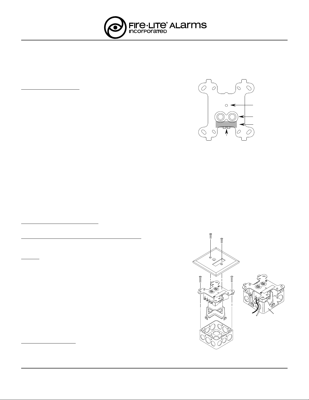
STATUS LED
ROTARY DECADE
ADDRESS SWITCHES
MODE TABS
M300(A) MAGNET
TEST POSITION
ISOLATED
QUADRANT
I300(A) FAULT ISOLATOR MODULE INSTALLATION INSTRUCTIONS
This information is included as a quick reference installation guide. Refer to the appropriate Fire-Lite control panel installation manual for detailed system information. If the modules will be installed in an existing operational system, inform the operator and local
authority that the system will be temporarily out of service. Disconnect power to the control panel before installing the modules.
NOTICE: This manual should be left with the owner/user of this equipment.
GENERAL DESCRIPTION
M300(A) MONITOR MODULES provide a two-wire, or fault-tolerant, initiating
circuit for normally open contact fire alarm and supervisory devices, or either
normally open or normally closed security devices. The LED indicator can be
latched on or returned to the normal mode by code command from the panel.
Rotary decade switches are used to set the address of each module.
C304(A) CONTROL MODULES allow a compatible control panel to switch discrete contacts by code command. The control module offers a status LED that
can be latched on or returned to the normal mode by code command from the
panel. Rotary decade switches are used to set the address of each module.
The control module offers two modes of switching operation. As shipped, the
Figure 1. Montior and Control Module
Conrols and Indicators
module is configured for switching an external power source to notification appliances. The external power source can be a DC power supply or an audio amplifier (up to 70.7 Vrms). In this mode, the module reports supervision status of the connected loads to the control panel. Load circuit status is reported as a normal, open, or
shorted circuit. Two pairs of output termination points are available for fault-tolerant wiring. The second mode of switching operation allows the panel to control one Form-C (SPDT) set of contacts.
by the module.
This mode is enabled by breaking two external tabs on the module.
Circuit connections to the contacts are not supervised
A78-2318-01
I300(A) FAULT ISOLATOR MODULES enable part of the communications loop to continue operating when a short circuit occurs on it. An LED indicator blinks in the normal condition and turns on during a short circuit condition. The module will automatically restore the entire communications loop to the normal condition when the short circuit is removed. (The isolator module does not have decade switches.)
COMPATIBILITY REQUIREMENTS
To insure proper operation, these modules must be connected to addressable, listed compatible Fire-Lite control panels only.
MOUNTING M300(A), C304(A), AND I300(A) DEVICES
M300(A), C304(A), and I300(A) modules mount directly to 4 inch square elec-
1
trical boxes as shown in Figure 2A. The box must have a min. depth of 2
/8".
WIRING
NOTE: All wiring must conform to applicable local codes, ordinances, and
regulations. When using control modules in nonpower limited applications, the CB500 Module Barrier must be used to meet UL requirements for the separation of power-limited and nonpower-limited termi-
1
nals and wiring. The barrier must be inserted in a 4"x4"x2
/8" junction
box, and the control module must be placed into the barrier and attached to the junction box (Figure 2A). The power-limited wiring must
be placed into the isolated quadrant of the module barrier (Figure 2B).
1. Install module wiring in accordance with the job drawings and appropriate
wiring diagrams (Figures 3 - 10).
2. Set the address on the M300 and C304 per job drawings. Record this address and loop on the front of the module, if desired.
Figure 2B.
A78-2611-00
3. Secure module to electrical box (supplied by installer), as shown in Figure 2A.
M300(A) MAGNET TEST
The M300(A) Monitor module can be tested with Fire-Lite's M02-04-01 Test
Magnet (see Figure 1). The magnet test checks the module electronics and
connections to the control panel. Interfaced initiating and indicating devices
must be tested independently.
F300-03-01 1 I56-570-05
Fire-Lite Alarms, Inc., 12 Clintonville Rd, Northfield , CT 06472-1652 (203) 484-7161
Figure 2A. Module
Mounting with Barrier
A78-2610-00
Page 2
1 (-)
2 (+)
MODULE
FROM PANEL OR
(+)
(-)
TO NEXT
(+)
(-)
DEVICE
(+)
(-)
3 (-)
4 (+)
(+) 9
(-) 8
(-) 7
(+) 6
XXX 5
CONTROL
(-)
(+)
(-)
(+)
47K EOL
RESISTOR
A2143-00
UL LISTED EOL RELAY
SHOWN ENERGIZED
A77-716B
XXX - DO NOT
USE TERMINAL 5
TO NEXT CONTROL MODULE OR END
OF LINE RELAY (EOLR); ONE EOLR
REQUIRED PER BRANCH CIRCUIT
MODULE POLARITIES ARE
SHOWN IN ALARM
CONNECT MODULES TO LISTED COMPATIBLE
USE UL LISTED INDICATING APPLIANCES
RESISTIVE: 2 A @ 30 VDC
INDUCTIVE: 1 A @ 30 VDC (.6 PF)
PILOT DUTY: .6 A @ 30 VDC (.35 PF)
MAXIMUM LOAD:
SEE FIRE-LITE PRODUCT
MANUAL FOR
WIRE SPECIFICATIONS
BRANCH CIRCUIT
3 & 4. BREAK WIRE RUN TO PROVIDE
SUPERVISION OF CONNECTIONS.
DO NOT LOOP WIRE ON TERMINALS
ALL WIRING SHOWN IS SUPERVISED AND POWER LIMITED
(-)
(+)
IS
OLATED, REGULATED
POWER SUPPLY, LISTED FOR FIRE
PROTECTION WITH BATTERY BACKUP
(MONITOR LOSS OF PRIMARY POWER)
C304(A)
FIRE-LITE CONTROL PANELS ONLY
INDICATING APPLIANCE CIRCUIT (IAC) - NFPA STYLE W
COMMUNICATION LINE
PREVIOUS DEVICE
EXTERNAL POWER SOURCE MUST BE
POWER LIMITED PER NFPA 70
FROM PANEL OR
PREVIOUS DEVICE
(–)
(+)
(–)
TO NEXT
(+)
DEVICE
ANY NUMBER OF UL LISTED CONTACT CLOSURE
DEVICES MAY BE USED. DO NOT MIX FIRE
ALARM INITIATING, SUPERVISORY, OR
SECURITY DEVICES ON THE SAME MODULE.
47 K EOL
RESISTOR
A2143-00
INITIATING DEVICE CIRCUIT - NFPA STYLE A OR B
POWER LIMITED: 230 µA MAX @ 12 VDC MAX
IDC INSTALLATION WIRING SHALL NOT
EXCEED 40 OHMS OR 2500 FEET, 12 - 18 AWG.
INSTALL CONTACT CLOSURE DEVICES PER
MANUFACTURER'S INSTALLATION INSTRUCTIONS.
CONNECT MODULES TO LISTED COMPATIBLE
FIRE-LITE CONTROL PANELS ONLY
COMMUNICATION LINE
SEE FIRE-LITE PRODUCT
MANUAL FOR WIRE SPECIFICATIONS
ALL WIRING SHOWN IS SUPERVISED AND POWER LIMITED
MONITOR
MODULE
M300(A)
(–)
(+)
1 (–)
2 (+)
(–)9
(+)8
(+)7
(–)6
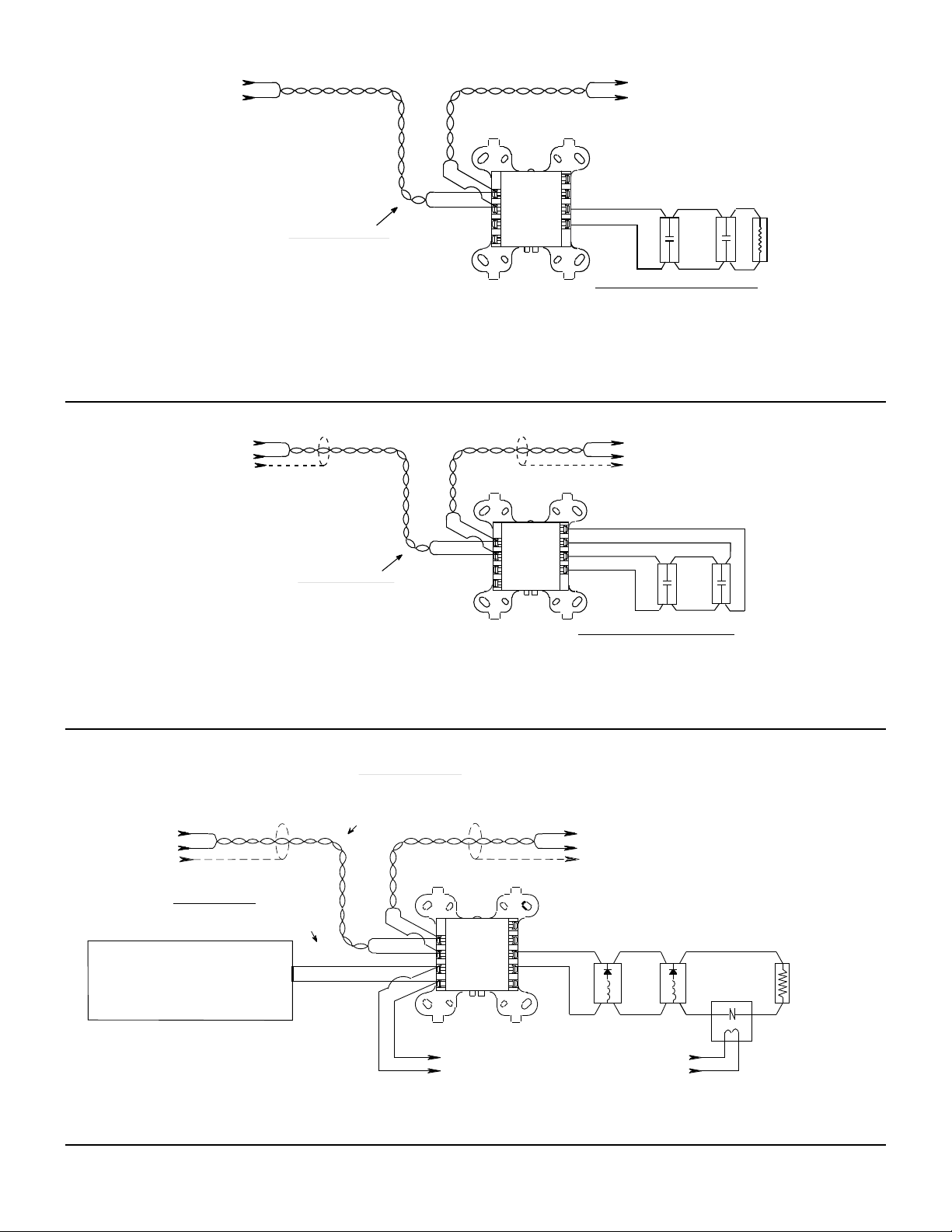
FIGURE 3. TYPICAL M300 2-WIRE INITIATING CIRCUIT CONFIGURATION, NFPA STYLE A OR B
CONNECT MODULES TO LISTED COMPATIBLE
FIRE-LITE CONTROL PANELS ONLY
FROM PANEL OR
PREVIOUS DEVICE
(-)
(+)
COMMUNICATION LINE
SEE FIRE-LITE PRODUCT
MONITOR
MODULE
M300(A)
(–)
(+)
MANUAL FOR WIRE
SPECIFICATIONS
ALL WIRING SHOWN IS SUPERVISED AND POWER LIMITED
1 (–)
2 (+)
(–)
TO NEXT
(+)
DEVICE
ANY NUMBER OF UL LISTED CONTACT CLOSURE
DEVICES MAY BE USE. DO NOT MIX FIRE
ALARM INITIATING, SUPERVISORY, OR
SECURITY DEVICE ON THE SAME MODULE.
(–)9
(+)8
(+)7
(–)6
INITIATING DEVICE CIRCUIT - NFPA STYLE D
POWER LIMITED: 230 µA MAX @ 12 VDC MAX
IDC INSTALLATION WIRING SHALL NOT
EXCEED 40 OHMS OR 2500 FEET, 12 - 18 AWG.
INSTALL CONTACT CLOSURE DEVICES PER
MANUFACTURER'S INSTALLATION INSTRUCTIONS.
EOL RESISTOR
IS INTERNAL AT
TERMINALS 8 & 9.
FIGURE 4. TYPICAL M300 FAULT TOLERANT INITIATING CIRCUIT CONFIGURATION, NFPA STYLE D
A78-2280-05
A78-2281-03
FIGURE 5. TYPICAL C304 INDICATING CIRCUIT CONFIGURATION, NFPA STYLE W
F300-03-01 2 I56-570-05
A78-2282-05
Page 3

CONNECT MODULES TO LISTED COMPATIBLE
FIRE-LITE CONTROL PANELS ONLY
FROM PANEL OR
PREVIOUS DEVICE
DO NOT LOOP WIRE ON TERMINALS
3 & 4. BREAK WIRE RUN TO PROVIDE
ISOLATED REGULATED
POWER SUPPLY, LISTED FOR FIRE
PROTECTION WITH BATTERY BACKUP
(MONITOR LOSS OF PRIMARY POWER)
EXTERNAL POWER SOURCE MUST BE
POWER LIMITED PER NFPA 70
(–)
(+)
BRANCH CIRCUIT
SUPERVISION OF CONNECTIONS.
(–)
(+)
*Canadian models have a resistive rating of 1.5A @ 30 VDC in this configuration.
FIGURE 6. TYPICAL C304 FAULT TOLERANT INDICATING CIRCUIT CONFIGURATION, NFPA STYLE X
CONNECT MODULES TO LISTED COMPATIBLE
FIRE-LITE CONTROL PANELS ONLY
FROM PANEL OR
PREVIOUS DEVICE
DO NOT LOOP WIRE AROUND TERMINALS
SUPERVISION OF CONNECTIONS.
AUDIO AMPLIFIER
(–)
(+)
AUDIO BRANCH CIRCUIT
3 & 4. BREAK WIRE TO ENSURE
70.7 Vrms MAX.
SUPERVISION
WIRES MUST BE SUPERVISEDD PER NFPA
WHEN A 70.7V AUDIO AMPLIFIER IS USED, TERMINALS 1 AND 2 ARE POWER LIMITED,
WHILE TERMINALS 3-9 ARE NONPOWER LIMITED. IN THIS CASE THE CB500 BARRIER
IS REQUIRED. OTHERWISE, ALL TERMINAL WIRING IS POWER LIMITED.
INCLUDES A LABEL INDICATING WHICH TERMINALS ARE NONPOWER LIMITED. THIS
LABEL MUST BE PLACED OVER THE POWER-LIMITED TERMINAL INFORMATION ON
THE NAMEPLATE LABEL, PRESENT ON THE MODULE HOUSING.
THE CB500
FIGURE 7. TYPICAL C304 WIRING FOR SPEAKER SUPERVISION AND SWITCHING, NFPA STYLE W
COMMUNICATION LINE
SEE FIRE-LITE PRODUCT
MANUAL FOR
WIRE SPECIFICATIONS
CONTROL
MODULE
C304(A)
(–)
(+)
1 (–)
2 (+)
3 (–)
4 (+)
XXX - DO NOT
USE TERMINAL 5
MODULE POLARITIES ARE
SHOWN IN ALARM
SEE FIRE-LITE PRODUCT
AMP. WIRE
(–)
(+)
CIRCUIT
(+) (–)
ALL WIRING SHOWN IS SUPERVISED AND POWER LIMITED
(–)
TO NEXT
(+)
DEVICE
INDICATING APPLIANCE CIRCUIT (IAC) - NFPA STYLE X
USE UL LISTED INDICATING APPLIANCES
MAXIMUM LOAD:
(+) 9
(–) 8
(–) 7
(+) 6
XXX 5
(–)
(+)
TO NEXT CONTROL MODULE OR END
OF LINE RELAY (EOLR); ONE EOLR
REQUIRED PER 24 VDC BRANCH CIRCUIT
COMMUNICATION LINE
MANUAL FOR
WIRE SPECIFICATIONS
(–)
(+)
CONTROL
MODULE
C304(A)
(–)
(+)
(+) 9
(–) 8
1 (–)
(–) 7
2 (+)
(+) 6
3 (–)
XXX 5
4 (+)
XXX - DO NOT
USE TERMINAL 5
TO NEXT CONTROL MODULE
LAST MODULE MUST RETURN
WIRES FOR SUPERVISION
MODULE POLARITIES ARE
SHOWN IN ALARM
RESISTIVE: 2 A @ 30 VDC*
INDUCTIVE: 1 A @ 30 VDC (.6 PF)
PILOT DUTY: .6 A @ 30 VDC (.35 PF)
(–)
(+)
ALL WIRING SHOWN IS SUPERVISED.
TO NEXT
DEVICE
SPEAKER SWITCHING CIRCUIT - NFPA STYLE W
SPEAKERS MUST BE LISTED FOR FIRE PROTECTION
MAXIMUM LOAD: 43.75 WATTS MAX.
(–)
(+)
UL LISTED EOL RELAY
SHOWN ENERGIZED
24 VDC COIL
A77-716B
UP TO 70.7 Vrms
(.35 POWER FACTOR)
(–)
(+)
47 K EOL
RESISTOR
A2143-00
EOL RESISTOR IS
INTERNAL ACROSS
TERMINALS 8 AND 9
A78-2283-05
A78-2284-04
COMMUNICATION LINE
SEE FIRE-LITE PRODUCT
MANUAL FOR
CONNECT MODULES TO LISTED COMPATIBLE
FIRE-LITE CONTROL PANELS ONLY
FROM PANEL OR
PREVIOUS DEVICE
DO NOT LOOP WIRE AROUND TERMINALS
WIRES MUST BE SUPERVISEDD PER NFPA
WHEN A 70.7V AUDIO AMPLIFIER IS USED, TERMINALS 1 AND 2 ARE POWER LIMITED,
WHILE TERMINALS 3-9 ARE NONPOWER LIMITED. IN THIS CASE THE CB500 BARRIER
IS REQUIRED. OTHERWISE, ALL TERMINAL WIRING IS POWER LIMITED.
INCLUDES A LABEL INDICATING WHICH TERMINALS ARE NONPOWER LIMITED. THIS
LABEL MUST BE PLACED OVER THE POWER-LIMITED TERMINAL INFORMATION ON
THE NAMEPLATE LABEL, PRESENT ON THE MODULE HOUSING.
(–)
(+)
AUDIO BRANCH CIRCUIT
3 & 4. BREAK WIRE TO ENSURE
SUPERVISION OF CONNECTIONS.
AUDIO AMPLIFIER
70.7 Vrms MAX.
AMP. WIRE
SUPERVISION
CIRCUIT
THE CB500
(+) (–)
WIRE SPECIFICATIONS
(–)
(+)
(–)
(+)
USE TERMINAL 5
MODULE POLARITIES ARE
(–)
TO NEXT
(+)
DEVICE
CONTROL
MODULE
C304(A)
(+) 9
(–) 8
1 (–)
(–) 7
2 (+)
(+) 6
3 (–)
XXX 5
4 (+)
XXX - DO NOT
TO NEXT CONTROL MODULE
LAST MODULE MUST RETURN
WIRES FOR SUPERVISION
SHOWN IN ALARM
ALL WIRING SHOWN IS SUPERVISED.
SPEAKER SWITCHING CIRCUIT - NFPA STYLE X
SPEAKERS MUST BE LISTED FOR FIRE PROTECTION
MAXIMUM LOAD: 43.75 WATTS MAX.
UP TO 70.7 Vrms (.35 POWER FACTOR)
(–)
(+)
BYPASS CAPACITORS: 100 µf, 10V
EOL RESISTOR IS
(–)
INTERNAL ACROSS
TERMINALS 8 AND 9
(+)
A2143-20 NONPOLARIZED
<10 µA LEAKAGE
A78-2285-04
FIGURE 8. TYPICAL C304 FAULT TOLERANT WIRING FOR SPEAKER SUPERVISION AND SWITCHING, NFPA STYLE X
F300-03-01 3 I56-570-05
Page 4

CONNECT MODULES TO LISTED COMPATIBLE
CONTROL PANELS ONLY
FROM PANEL OR
PREVIOUS DEVICE
RELAY CONTACT RATINGS:
RESISTIVE: 2 A @ 30 VDC
INDUCTIVE: 1 A @ 30 VDC (.6 PF)
PILOT DUTY: .6 A @ 30 VDC (.35 PF)
.3 A @ 110 VDC (.35 PF)
.3 A @ 120 VAC (.35 PF)
(–)
(+)
COMMUNICATION LINE
SEE FIRE-LITE PRODUCT
MANUAL FOR WIRE
SPECIFICATIONS
(–)
(+)
NORMALLY OPEN
2 (+)
4
1 (–)
3
CONTROL
MODULE
C304(A)
(–)
(+)
9
8
7
RELAY COMMON
6
NORMALLY CLOSED
5
TO NEXT
DEVICE
BREAK OFF TABS
J1 & J2 TO ENABLE
FORM C OPERATION
FORM "C" RELAY OPERATION WHEN
BOTH TABS J1 AND J2 ARE BROKEN.
MODULE DOES NOT SUPERVISE CIRCUITS
A78-2286-03 A78-1953-02
CONTROLLED BY FORM C CONTACT.
J1 & J2
ALL WIRING SHOWN IS POWER LIMITED
FIGURE 9. C304 CONTROL MODULE IN RELAY OUTPUT MODE
INST ALLATION W ARNINGS AND NOTES
Control and isolator modules use a latching relay that can change states if it is subjected to mechanical shocks or jarring. As a
result, although modules are shipped with their relays in the open state, the contacts may have closed during shipment. Connecting an auxiliary control circuit to closed relay contacts in a control module can cause an unexpected, and possibly dangerous, activation of that circuit. Therefore, do NOT connect an auxiliary control circuit to the relay contacts before ensuring that
they are in their open (standby) state. Make sure that the contacts are open by allowing the control panel to poll the module at
least once, as indicated when the LED blinks.
If the contacts of several isolator modules are closed when system power is initially applied, it increases the load on upstream
modules, causing their relays to open. This prevents the proper application of power to the entire system. To correct this, connect a temporary jumper between terminals 2 and 3 on all isolator modules whose LEDs are continuously lit OR interrupt the
signal line circuit after the last open isolator. The panel must delay communications for at least one minute after power is applied to allow all system devices to power up past the 7 volt threshold.
FAULT ISOLATOR
MODULE
I300(A)
(–)
(+)
(–)
(+)
1 (–)
2 (+)
3 (–)
4 (+)
COMMUNICATION LINE
SEE FIRE-LITE PRODUCT
MANUAL FOR
WIRE SPECIFICATIONS
ALL WIRING SHOWN IS SUPERVISED AND POWER LIMITED.
(–)
(+)
(–)
(+)
FAULT ISOLATOR
MODULE
I300(A)
1 (–)
2 (+)
3 (–)
4 (+)
(–)
(–)
(+)
1 (–)
2 (+)
1 (–)
2 (+)
(–)
(+)
(–)
(+)
1 (–)
2 (+)
1 (–)
2 (+)
FAULT ISOLATOR
MODULE
I300(A)
(–)
(+)
(–)
(+)
1 (–)
2 (+)
3 (–)
4 (+)
(+)(–)
FIRE-LITE UL LISTED COMPATIBLE
CONTROL PANEL
(+)
(–)
FAULT ISOLATOR
MODULE
I300(A)
(–)
(+)
1 (–)
2 (+)
3 (–)
(–)
4 (+)
(+)
(–)
(+) (+)
(–)
(+)
1 (–)
2 (+)
GROUPS OF ADDRESSABLE DEVICES ARE SEPARATED BY FAULT ISOLATOR
A PAIR OF FAULT ISOLATOR MODULES WILL DISCONNECT A
1 (–)
2 (+)
MODULES. ANY COMBINATION OF COMPATIBLE,
LISTED DEVICES MAY BE MIXED WITHIN A GROUP.
GROUP OF DEVICES IF A SHORT CIRCUIT OCCURS ON THE
SIGNALING LINE CIRCUIT WITHIN THAT GROUP.
A78-2287-04
FIGURE 10. I300 FAULT ISOLATOR MODULE WIRING
F300-03-01 4 I56-570-05
© Fire-Lite Alarms, Inc. 1996
 Loading...