

Page 1

Field Charger/Power Supply
FCPS-24FS6 & FCPS-24FS8
FCPS-24FS6E & FCPS-24FS8E
FCPS-24FS6C & FCPS-24FS8C
Installation Manual
Document 51883-L8
8/30/13 Rev:
P/N 51883-L8:J1 ECN 13-201
J1
Page 2

Fire Alarm & Emergency Communication System Limitations
While a life safety system may lower insurance rates, it is not a substitute for life and property
insurance!
An automatic fire alarm system—typically made up of
smoke detectors, heat detectors, manual pull stations, audible
warning devices, and a fire alarm control panel (FACP) with
remote notification capability—can provide early warning of a
developing fire. Such a system, however, does not assure
protection against property damage or loss of life resulting
from a fire.
An emergency communication system—typically made up
of an automatic fire alarm system (as described above) and a
life safety communication system that may include an autonomous control unit (ACU), local operating console (LOC), voice
communication, and other various interoperable communication methods—can broadcast a mass notification message.
Such a system, however, does not assure protection against
property damage or loss of life resulting from a fire or life
safety event.
The Manufacturer recommends that smoke and/or heat
detectors be located throughout a protected premises
following the recommendations of the National Fire Protection
Association Standard 72 (NFPA 72), manufacturer's
recommendations, State and local codes, and the
recommendations contained in the Guide for Proper Use of
System Smoke Detectors, which is made available at no
charge to all installing dealers. This document can be found at
http://www.systemsensor.com/appguides/. A study by the
Federal Emergency Management Agency (an agency of the
United States government) indicated that smoke detectors
may not go off in as many as 35% of all fires. While fire alarm
systems are designed to provide early warning against fire,
they do not guarantee warning or protection against fire. A fire
alarm system may not provide timely or adequate warning, or
simply may not function, for a variety of reasons:
Smoke detectors may not sense fire where smoke cannot
reach the detectors such as in chimneys, in or behind walls, on
roofs, or on the other side of closed doors. Smoke detectors
also may not sense a fire on another level or floor of a building.
A second-floor detector, for example, may not sense a firstfloor or basement fire.
Particles of combustion or “smoke” from a developing fire
may not reach the sensing chambers of smoke detectors
because:
• Barriers such as closed or partially closed doors, walls,
chimneys, even wet or humid areas may inhibit particle or
smoke flow.
• Smoke particles may become “cold,” stratify, and not reach
the ceiling or upper walls where detectors are located.
• Smoke particles may be blown away from detectors by air
outlets, such as air conditioning vents.
• Smoke particles may be drawn into air returns before
reaching the detector.
The amount of “smoke” present may be insufficient to alarm
smoke detectors. Smoke detectors are designed to alarm at
various levels of smoke density. If such density levels are not
created by a developing fire at the location of detectors, the
detectors will not go into alarm.
Smoke detectors, even when working properly, have sensing
limitations. Detectors that have photoelectronic sensing
chambers tend to detect smoldering fires better than flaming
fires, which have little visible smoke. Detectors that have ionizing-type sensing chambers tend to detect fast-flaming fires
better than smoldering fires. Because fires develop in different
ways and are often unpredictable in their growth, neither type
of detector is necessarily best and a given type of detector
may not provide adequate warning of a fire.
Smoke detectors cannot be expected to provide adequate
warning of fires caused by arson, children playing with
matches (especially in bedrooms), smoking in bed, and violent
explosions (caused by escaping gas, improper storage of
flammable materials, etc.).
Heat detectors do not sense particles of combustion and
alarm only when heat on their sensors increases at a predetermined rate or reaches a predetermined level. Rate-of-rise
heat detectors may be subject to reduced sensitivity over time.
For this reason, the rate-of-rise feature of each detector
should be tested at least once per year by a qualified fire protection specialist. Heat detectors are designed to protect
property, not life.
IMPORTANT! Smoke detectors must be installed in the
same room as the control panel and in rooms used by the system for the connection of alarm transmission wiring, communications, signaling, and/or power. If detectors are not so
located, a developing fire may damage the alarm system,
compromising its ability to report a fire.
Audible warning devices such as bells, horns, strobes,
speakers and displays may not alert people if these devices
are located on the other side of closed or partly open doors or
are located on another floor of a building. Any warning device
may fail to alert people with a disability or those who have
recently consumed drugs, alcohol, or medication. Please note
that:
• An emergency communication system may take priority
over a fire alarm system in the event of a life safety emergency.
• Voice messaging systems must be designed to meet intelligibility requirements as defined by NFPA, local codes, and
Authorities Having Jurisdiction (AHJ).
• Language and instructional requirements must be clearly
disseminated on any local displays.
• Strobes can, under certain circumstances, cause seizures
in people with conditions such as epilepsy.
• Studies have shown that certain people, even when they
hear a fire alarm signal, do not respond to or comprehend
the meaning of the signal. Audible devices, such as horns
and bells, can have different tonal patterns and frequencies. It is the property owner's responsibility to conduct fire
drills and other training exercises to make people aware of
fire alarm signals and instruct them on the proper reaction
to alarm signals.
• In rare instances, the sounding of a warning device can
cause temporary or permanent hearing loss.
A life safety system will not operate without any electrical
power. If AC power fails, the system will operate from standby
batteries only for a specified time and only if the batteries have
been properly maintained and replaced regularly.
Equipment used in the system may not be technically compatible with the control panel. It is essential to use only equipment listed for service with your control panel.
Telephone lines needed to transmit alarm signals from a
premises to a central monitoring station may be out of service
or temporarily disabled. For added protection against telephone line failure, backup radio transmission systems are recommended.
The most common cause of life safety system malfunction is
inadequate maintenance. To keep the entire life safety system
2 FCPS-24FS Series Instruction Manual — P/N 51883-L8:J1 8/30/13
Page 3

Installation Precautions
Adherence to the following will aid in problem-free installation with long-term reliability:
WARNING - Several different sources of power can be
connected to the fire alarm control panel. Disconnect all
sources of power before servicing. Control unit and associated equipment may be damaged by removing and/or inserting cards, modules, or interconnecting cables while the unit is
energized. Do not attempt to install, service, or operate this
unit until manuals are read and understood.
CAUTION - System Re-acceptance Test after Software
Changes: To ensure proper system operation, this product
must be tested in accordance with NFPA 72 after any programming operation or change in site-specific software. Reacceptance testing is required after any change, addition or
deletion of system components, or after any modification,
repair or adjustment to system hardware or wiring. All components, circuits, system operations, or software functions known
to be affected by a change must be 100% tested. In addition,
to ensure that other operations are not inadvertently affected,
at least 10% of initiating devices that are not directly affected
by the change, up to a maximum of 50 devices, must also be
tested and proper system operation verified.
This system meets NFPA requirements for operation at 0-49º
C/32-120º F and at a relative humidity . However, the useful
life of the system's standby batteries and the electronic components may be adversely affected by extreme temperature
ranges and humidity. Therefore, it is recommended that this
system and its peripherals be installed in an environment with
a normal room temperature of 15-27º C/60-80º F.
Verify that wire sizes are adequate for all initiating and indicating device loops. Most devices cannot tolerate more than a
10% I.R. drop from the specified device voltage.
Like all solid state electronic devices, this system may
operate erratically or can be damaged when subjected to lightning induced transients. Although no system is completely
immune from lightning transients and interference, proper
grounding will reduce susceptibility. Overhead or outside aerial
wiring is not recommended, due to an increased susceptibility
to nearby lightning strikes. Consult with the Technical Services Department if any problems are anticipated or encountered.
Disconnect AC power and batteries prior to removing or
inserting circuit boards. Failure to do so can damage circuits.
Remove all electronic assemblies prior to any drilling, filing,
reaming, or punching of the enclosure. When possible, make
all cable entries from the sides or rear. Before making modifications, verify that they will not interfere with battery, transformer, or printed circuit board location.
Do not tighten screw terminals more than 9 in-lbs. Overtightening may damage threads, resulting in reduced terminal
contact pressure and difficulty with screw terminal removal.
This system contains static-sensitive components.
Always ground yourself with a proper wrist strap before handling any circuits so that static charges are removed from the
body. Use static suppressive packaging to protect electronic
assemblies removed from the unit.
Follow the instructions in the installation, operating, and programming manuals. These instructions must be followed to
avoid damage to the control panel and associated equipment.
FACP operation and reliability depend upon proper installation.
Precau-D1-9-2005
FCC Warning
WARNING: This equipment generates, uses, and can
radiate radio frequency energy and if not installed and
used in accordance with the instruction manual may
cause interference to radio communications. It has been
tested and found to comply with the limits for class A
computing devices pursuant to Subpart B of Part 15 of
FCC Rules, which is designed to provide reasonable
protection against such interference when devices are
operated in a commercial environment. Operation of this
equipment in a residential area is likely to cause interference, in which case the user will be required to correct
the interference at his or her own expense.
Canadian Requirements
This digital apparatus does not exceed the Class A limits
for radiation noise emissions from digital apparatus set
out in the Radio Interference Regulations of the Canadian Department of Communications.
Le present appareil numerique n'emet pas de bruits radioelectriques depassant les limites applicables aux appareils numeriques de la classe A prescrites dans le
Reglement sur le brouillage radioelectrique edicte par le
ministere des Communications du Canada.
LiteSpeed™ is a trademark; and FireLite® Alarms is a registered trademark of Honeywell International Inc. Microsoft® and Windows® are registered
trademarks of the Microsoft Corporation.
©2013 by Honeywell International Inc. All rights reserved. Unauthorized use of this document is strictly prohibited.
FCPS-24FS Series Instruction Manual — P/N 51883-L8:J1 8/30/13 3
Page 4

Software Downloads
In order to supply the latest features and functionality in fire alarm and life safety technology to our customers, we make
frequent upgrades to the embedded software in our products. To ensure that you are installing and programming the latest
features, we strongly recommend that you download the most current version of software for each product prior to
commissioning any system. Contact Technical Support with any questions about software and the appropriate version for
a specific application.
Documentation Feedback
Your feedback helps us keep our documentation up-to-date and accurate. If you have any comments or suggestions about
our online Help or printed manuals, you can email us.
Please include the following information:
•Product name and version number (if applicable)
•Printed manual or online Help
•Topic Title (for online Help)
•Page number (for printed manual)
•Brief description of content you think should be improved or corrected
•Your suggestion for how to correct/improve documentation
Send email messages to:
FireSystems.TechPubs@honeywell.com
Please note this email address is for documentation feedback only. If you have any technical issues, please contact
Technical Services.
4 FCPS-24FS Series Instruction Manual — P/N 51883-L8:J1 8/30/13
Page 5

Table of Contents
Section 1: System Overview....................................................................................................8
1.1: General...........................................................................................................................................................8
1.2: Features..........................................................................................................................................................8
1.3: Start-up Procedure .........................................................................................................................................9
1.4: Jumpers ........................................................................................................................................................10
1.4.1: Jumper JP1 - Ground Fault Detection ...............................................................................................10
1.4.2: Jumpers JP2 and JP3: Coded/Noncoded Input Selection ..................................................................10
1.5: LED Indicators.............................................................................................................................................10
1.6: Specifications...............................................................................................................................................10
1.7: General.........................................................................................................................................................12
Section 2: Installation.............................................................................................................14
2.1: Backbox Mounting ......................................................................................................................................14
2.2: NAC Circuit Wiring.....................................................................................................................................16
2.2.1: Style Y (Class B) ...............................................................................................................................16
2.2.2: ZNAC-4 Class A Option Module......................................................................................................16
2.3: Addressable Module Mounting ...................................................................................................................17
2.4: NEC Power-limited (Class 2) Wiring Requirements...................................................................................18
Section 3: Programming Options.......................................................................................... 19
3.1: DIP Switch Settings.....................................................................................................................................20
3.2: Programmable Features Description............................................................................................................21
3.2.1: Synchronization Type Selection........................................................................................................21
Maximum Number of Strobes for Synchronization .............................................................................21
3.2.2: Synchronization Mode - Master/Slave ..............................................................................................21
3.2.3: AC Fail Delay/Aux. Trouble Relay Function....................................................................................22
3.2.4: Input/Output Function .......................................................................................................................22
Auxiliary Power Control ......................................................................................................................23
3.2.5: Charger Enable/Disable.....................................................................................................................23
3.2.6: Door Closers......................................................................................................................................23
Section 4: Trouble Supervision............................................................................................. 25
4.1: Supervision via FACP Notification Appliance Circuit................................................................................25
4.1.1: Supervision of FACP to FCPS wiring...............................................................................................25
4.1.2: Supervision of FCPS-24FS Faults.....................................................................................................25
4.1.3: Aux. Trouble Relay/AC Fail Relay ...................................................................................................25
4.2: AC Loss Reporting Delay............................................................................................................................26
Section 5: Applications .......................................................................................................... 27
5.1: Controlling Four NACs With One Input and Selective Silence ..................................................................27
5.2: Controlling Three NACs and One Door Holder With One Input................................................................29
5.3: Split Temporal Mode of Operation..............................................................................................................31
5.4: Remote Supply With Resettable and Nonresettable Power.........................................................................33
5.5: Master FACP with Slave FCPS-24FS Power Supply..................................................................................35
5.6: Master FCPS-24FS Power Supply Connected to FACP..............................................................................36
5.7: Canadian Applications.................................................................................................................................36
Section 6: Power Supply Requirements............................................................................... 38
6.1: Overview......................................................................................................................................................38
6.2: Calculating the AC Branch Circuit..............................................................................................................38
6.3: Calculating the System Current Draw .........................................................................................................39
6.3.1: Overview ...........................................................................................................................................39
6.3.2: How to Calculate System Current Draw ...........................................................................................39
6.4: Calculating the Battery Size ........................................................................................................................41
6.4.1: NFPA Battery Requirements .............................................................................................................41
6.4.2: Selecting and Locating Batteries .......................................................................................................41
FCPS-24FS Series Instruction Manual — P/N 51883-L8:J1 8/30/13 5
Page 6

Table of Contents
Appendix A: Wire Requirements........................................................................................... 43
Index ........................................................................................................................................44
6 FCPS-24FS Series Instruction Manual — P/N 51883-L8:J1 8/30/13
Page 7

It is imperative that the installer understand the requirements of the Authority Having Jurisdiction
(AHJ) and be familiar with the standards set forth by the following regulatory agencies:
• Underwriters Laboratories Standards
• NFPA 72 National Fire Alarm Code
Before proceeding, the installer should be familiar with the following documents.
NFPA Standards
NFPA 72 National Fire Alarm Code
NFPA 70 National Electrical Code
Underwriters Laboratories Documents:
UL 464 Audible Signaling Appliances
UL 864 Standard for Control Units for Fire Protective Signaling Systems
UL 1638 Visual Signaling Appliances
UL 1971 Signaling Devices for Hearing Impaired
UL 2572 Standard for Mass Notification Systems
NOTE: Mass Notification is not listed in Canada. Any part number that has a suffix of “C” is a
Canadian part number and will not have Mass Notification.
CAN/ULC - S524-01 Standard for Installation of Fire Alarm Systems
CAN/ULC-S527-99 Standard for Control Units for Fire Alarm Systems
Other:
NEC Article 250 Grounding
NEC Article 300 Wiring Methods
NEC Article 760 Fire Protective Signaling Systems
Applicable Local and State Building Codes
Requirements of the Local Authority Having Jurisdiction (LAHJ)
Canadian Electrical Code, Part 1
Other Fire•Lite Documents:
Device Compatibility Document Document #15384
This product has been certified to comply with the requirements in the Standard for Control Units
and Accessories for Fire Alarm Systems, UL 864, 9th Edition. Operation of this product with products not tested for UL 864, 9th Edition has not been evaluated. Such operation requires the
approval of the local Authority Having Jurisdiction (AHJ).
FCPS-24FS Series Instruction Manual — P/N 51883-L8:J1 8/30/13 7
Page 8

The FCPS-24FS6 is a 6 amp power supply and the FCPS-24FS8 is an 8 amp power supply. Each
FCPS-24FS power supply is a compact, cost-effective, remote power supply and battery charger
which provides ADA compatible strobe synchronization. Each remote power supply consists of a
filtered 24 VDC output that can be configured to drive four Style Y (Class B) NACs (Notification
Appliance Circuits). The four circuits can be configured for Style Z (Class A) with the optional
ZNAC-4 Class A converter module. Alternatively, the four output circuits may be configured as 24
VDC resettable or nonresettable power outputs. The input circuits, which control the power supply
operation, are triggered by the reverse polarity of an NAC or by a 12 VDC or 24 VDC power
source. The power supplies are compatible with 12 VDC and 24 VDC control panels.
The FCPS-24FS6E and FCPS-24FS8E offer the same features as the FCPS-24FS6 and FCPS24FS8 respectively but allow connection to 220/240 VAC. Unless otherwise specified, the information in this manual applies to both the 110/120 VAC versions and the 220/240 VAC versions of
the power supplies.
The FCPS-24FS6C and FCPS-24FS8C are the Canadian versions which offer the same features as
the FCPS-24FS6 and FCPS-24FS8 respectively. Unless otherwise specified, the information in this
manual also applies to the Canadian versions of the power supplies.
1.1 General
The FCPS-24FS power supplies can be used as remotely mounted power supplies and battery chargers to power four noncoded or coded NACs. The Main FACP (Fire Alarm Control Panel) NAC(s)
is connected to the remote power supply input circuit(s). When the control input circuit activates
due to reverse polarity of the NAC from the FACP, the power supply will activate its Notification
Appliance Circuits.
Section 1: System Overview
During the inactive or nonalarm state, the power supply supervises its NAC field wiring for short
and open conditions. AC fail, battery, charger and ground fault troubles will also be monitored by
the power supply. If an NAC or power supply fault is detected, the power supply Normally-Closed
Trouble contact will open.
If an alarm condition occurs and the NAC is activated, the supervision is disabled and the Notification Appliance Circuit is no longer supervised (except for shorts). Supervision of other power supply faults such as low battery, AC loss, ground fault and battery charger trouble will continue and
may be monitored via the Trouble relay contacts.
1.2 Features
• Self-contained in a lockable cabinet
• 24 VDC remote power supply
• Outputs are completely power-limited (Class 2)
• Two optically-isolated input/control circuits, compatible with 12 VDC and 24 VDC control
• Four output circuits:
• NAC Trouble LED - blinks to indicate the number of the circuit in trouble
panel NACs
– Fully filtered power
– Four 24 VDC Style Y (Class B) NACs
– Optional ZNAC-4 Class A converter module for conversion to Style Z NACs
– Alternatively, all four circuits may be configured as 24 VDC special application power
outputs
– Output circuits may be configured as resettable or nonresettable
8 FCPS-24FS Series Instruction Manual — P/N 51883-L8:J1 8/30/13
Page 9

Start-up Procedure System Overview
• Maximum current available for any one output circuit: 3.0 amps, special application, 300mA
regulated
• Maximum total continuous current available:
– 4.0 amps for FCPS-24FS6
– 6.0 amps for FCPS-24FS8
• Maximum total short term current (one hour maximum):
– 6.0 amps for FCPS-24FS6
– 8.0 amps for FCPS-24FS8
• Integral supervised battery charger for lead acid batteries only
• Capable of charging 7.0 AH to 18.0 AH (Amp Hour) batteries
• Fully supervised power supply, battery and NACs
• Selectable Strobe Synchronization for NACs (System Sensor, Gentex and Wheelock)
• Coded signal synchronization
• Fixed terminal blocks for field wiring capable of accepting 12 - 22 AWG wire
• Selectable Ground Fault detection by jumper JP1
• Power supply trouble Form-C relay contacts (fail-safe)
• Optional delay of AC loss reporting for 2 hours
• Auxiliary Special Application Power Output for SLC modules (500 mA maximum) with
optional reset for 4-wire smoke detectors
• Mounting location for optional addressable control module
1.3 Start-up Procedure
1. Configure the power supply jumpers as described in “Jumpers” on page 10.
2. Install the power supply as described in“Installation” on page 14.
3. Program the power supply as described in “Programming Options” on page 19.
4. Wire the power supply circuits, referring to the options described in“Trouble Supervision” on
page 25 and the application examples in“Applications” on page 27.
5. Connect primary power source wiring while observing the following:
– Make certain that the AC mains circuit breaker is off before making any wiring connections
between the mains and the power supply.
– Make certain primary power source is 120 VAC, 60 Hz, 3.2 amps.
– Run a pair of wires (with ground conductor) from the protected premises main breaker box
to TB1 of the power supply main circuit board.
– Use 14 AWG (1.6 mm O.D.) or heavier gauge wire with 600V insulation.
6. Apply power to the power supply using the following procedure:
– Apply AC power by turning on the AC mains circuit breaker connected to the power supply.
– Connect a properly charged battery to connector JP4 on the power supply main circuit
board.
FCPS-24FS Series Instruction Manual — P/N 51883-L8:J1 8/30/13 9
Page 10

System Overview Jumpers
!
Jumper positions shown
for noncoded (steady)
source voltage
JP3
JP2
jumpers
24s8jp3b.wmf
1.4 Jumpers
CAUTION: DISCONNECT POWER
REMOVE ALL POWER (AC & DC) BEFORE CUTTING OR MOVING ANY JUMPERS.
1.4.1 Jumper JP1 - Ground Fault Detection
The Ground Detection circuit monitors for zero impedance between the power supply and ground.
Jumper JP1 is located in the top right section of the power supply circuit board. Cutting JP1 will
disable ground fault detection by the power supply. This should only be done if ground faults are
being monitored by a panel connected to the FCPS power supply.
1.4.2 Jumpers JP2 and JP3: Coded/Noncoded Input Selection
Jumpers JP2 and JP3 are located in the top right section of the power
supply circuit board. JP2 is used for Control Input Circuit #1 and
JP3 is used for Control Input Circuit #2. The position of these jumpers will depend on the type of signal being fed to the input circuits:
• If the source voltage to the input circuit is a noncoded (steady
voltage) input signal, the jumper for the corresponding input
circuit should be in the default position which jumpers the
bottom two pins (as illustrated in drawing at left).
• If the source voltage to the input circuit is coded (variable
voltage), the jumper for the corresponding input circuit should
be moved to jumper the top two pins.
1.5 LED Indicators
1.6 Specifications
10 FCPS-24FS Series Instruction Manual — P/N 51883-L8:J1 8/30/13
• AC Power on (green) LED - indicates AC power is present
• Ground Fault (yellow) LED - indicates a ground fault condition (zero impedance to ground)
• Battery Trouble (yellow) LED - indicates low or no battery
• NAC Trouble (yellow) LED - indicates a Notification Appliance Circuit trouble (blinks once
for Circuit 1 trouble, twice for Circuit 2 trouble, three times for Circuit 3 trouble and four times
for Circuit 4 trouble. Note that multiple circuits in trouble will cause the LED to blink the
number of the circuit with the highest number)
• ChargerTrouble/AC Loss (yellow) LED - indicates a charger fault or loss of AC power:
– If AC is applied to the power supply without a battery connected, both the Charger
Trouble/AC Loss LED and Battery Trouble LED will turn on simultaneously, indicating that
a battery is not connected.
– When a battery is connected and the power supply is in Normal Mode, if the battery voltage
drops too low or the battery is disconnected, only the Battery Trouble LED will turn on.
– When a battery is connected and the charger develops a problem, only the Charger
Trouble/AC Loss LED will turn on.
Refer to Figure 1.1 on page 12 for terminal locations.
Primary AC Power - TB1
• FCPS-24FS6(C) & FCPS-24FS8(C): 120 VAC, 60 Hz, 3.2 amps maximum
• FCPS-24FS6E & FCPS-24FS8E: 240 VAC, 50 Hz, 1.6 amps maximum
• Wire size: minimum #14 AWG with 600V insulation
Page 11

Specifications System Overview
Control Input Circuits - TB4, Terminals 3 (+) & 4 (-) and 7 (+) & 8 (-)
• Trigger Input Voltage: 9 to 32 VDC
• Input Current Draw in Alarm Polarity:
– 16 to 32 volts, 2.0 mA maximum per input
– 9 to 16 volts, 1.0 mA maximum per input
NAC/Output Circuits - TB2, Terminals 1 (+) & 2 (-), 3 (+) & 4 (-), 5 (+) & 6 (-) and
7 (+) & 8 (-) alarm polarity
• Supervised, and power-limited (Class 2)
• Voltage Rating: 24 VDC filtered
• Current:
– Maximum for any one circuit - 3.0 amps, special application, 300mA, regulated
– Maximum total continuous
current for all output:
FCPS-24FS6 - 4.0 amps
FCPS-24FS8 - 6.0 amps
– Maximum total short term
current (one hour maximum) for all outputs:
FCPS-24FS6 - 6.0 amps
FCPS-24FS8 - 8.0 amps
• Output Circuit Types:
– Four Style Y NACs (require 4.7 KΩ End-of-Line Resistors) or
Style Z NACs using the optional ZNAC-4 Class A converter module
OR
– Four resettable or nonresettable 24 VDC power outputs
• Refer to the Fire•Lite Device Compatibility Document #15384 for listed compatible devices.
• For wiring requirements, refer to “Wire Requirements” on page 43.
Trouble Relay Contact Rating - TB5
• Fail-safe Form-C relay (normally energized, transfers with loss of power)
• 5.0 amps @ 24 VDC or 5.0 amps @ 30 VAC
Secondary Power (battery) Charging Circuit - JP4
• Supervised, nonpower-limited
• Supports lead acid type batteries only
• Float Charge Voltage: 27.6 VDC
• Maximum Charge Current: 1.5 A
• Battery fuse (F1) 15A, 32V (Canadian version is nonreplaceable 12A, 32V)
• Maximum Battery Capacity: 18.0 AH
• Minimum Battery Capacity: 7.0 AH
• Power supply draws maximum standby current of 65 mA from batteries
Auxiliary Special Application Power Output - TB4 Terminals 9 (+) & 10 (-)
• Special application power
• Power-limited (Class 2), nonsupervised
• Voltage Rating: 24 VDC
• Current:
– 170 mA maximum with internal 7.0 Amp Hour batteries
FCPS-24FS Series Instruction Manual — P/N 51883-L8:J1 8/30/13 11
Page 12
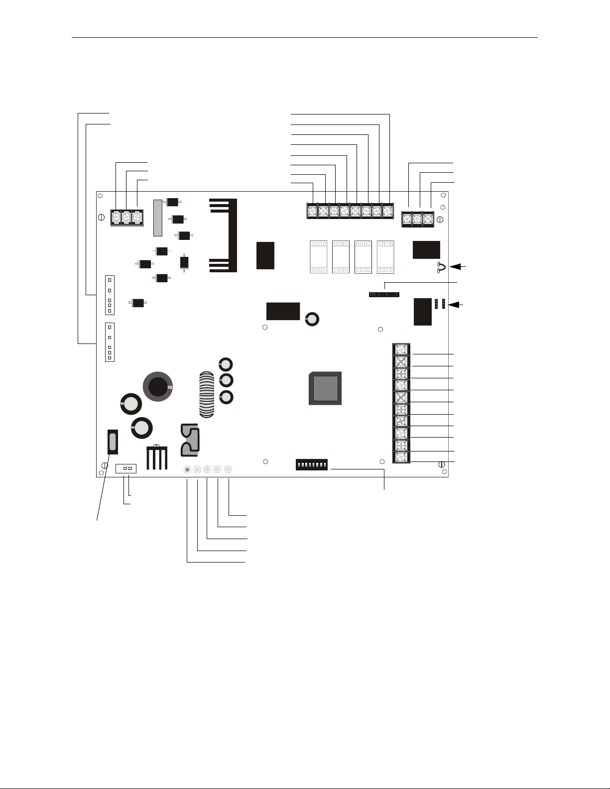
System Overview General
1 2 3 4 5 6 7 8
ON
TB1
J2
TRANSFORMER 2
TRANSFORMER 1
J1
F1
JP4
SW1
TB4
JP3
J3
TB5
TB2
JP1
JP2
- +
EARTH NEUT HOT
OUT4
- NAC4 +
OUT3
- NAC3 +
OUT2
- NAC2 +
OUT1
- NAC1 +
8 7 6 5 4 3 2 1
3 2 1
10
9
8
7
6
5
4
3
2
1
AUX -
IN2-
IN2+
OUT1-
OUT1+
IN1-
IN1+
SYNC IN -
SYNC IN +
AUX +
NO NC
AUX TBL
COM
BATTERY
AC
BATT
AC/
CHGR
GND
FLT
NAC
TRBL
Figure 1.1 FCPS-24FS Board Layout
- Aux. Common
+ Aux. 24 VDC*
- Control Input 2
+ Control Input 2
- Out Common
+ Out/Trouble Contact
- Control Input 1
+ Control Input 1
- Sync Input
+ Sync Input
NAC/Out 1 +
NAC/Out 1 -
NAC/Out 2 +
NAC/Out 2 -
NAC/Out 3 +
NAC/Out 3 -
NAC/Out 4 +
NAC/Out 4 -
Supervised,
Nonpower-limited
Earth
AC Neutral
AC Hot
Trouble Relay
Form-C Fail-safe
Nonsupervised
(shown energized)
Normally Open
Normally Closed
Common
JP1 Ground Fault
Detection
(cut to disable)
JP2 & JP3
Coded/Noncoded
Input Selection
JP4 Supervised
+ Battery
- Battery
18 AH, 24 VDC
Nonpowerlimited
LEDs
Charger Trouble/AC Loss (yellow)
NAC Trouble (yellow)
Battery Trouble (yellow)
Ground Fault (yellow)
AC Power (green)
SW1
Programming
DIP Switches
(change switch
settings only
when all power
(AC & DC) is
removed)
F1
Battery Fuse
15A, 32V
(Canadian version
is nonreplaceable
12 A, 32V)
Nonpower-limited
To Transformer #1
To Transformer #2
Auxiliary Output
500 mA Special
Application Power*
J3
ZNAC-4 Connector
*Note: Auxiliary Power
Output is power-limited
(Class 2) but not
supervised
Power-limited (Class 2), Supervised,
Special Application or regulated
24fs8brd.wmf
– 500 mA maximum with external 18.0 Amp Hour batteries
1.7 General
The FCPS may be used in a number of different applications. It may be used as a remotelymounted power supply and battery charger where it can provide up to four coded or noncoded, synchronized or nonsynchronized NACs (Notification Appliance Circuits). Alternatively, output #4
12 FCPS-24FS Series Instruction Manual — P/N 51883-L8:J1 8/30/13
Page 13

General System Overview
Style Y NAC
or Door
Holder Power
Output #4
AC Power
Figure 1.2 Simplified FCPS Block Diagram
Battery Charger
Style Y NAC
Output #3
Style Y NAC
Output #2
Style Y NAC
Output #1
Note: All NAC
outputs can be
converted to Style Z
with a ZNAC-4
option module
FCPS Trouble
Contact Output
24 VDC Specific
Application Power
NAC Control
Input #2
(from FACP)
NAC Control
Input #1
(from FACP)
Sync. Input
Input/Output Functions are Programmable
by SW1 DIP Switch Settings
24fsblok.wmf
can be used as a door holder circuit which will provide a steady 24 VDC output until an alarm condition or AC fail condition causes it to drop to 0 VDC following a 10 second delay. All four outputs can also provide power.
One possible application for the FCPS remote power supply utilizes the NAC repeater feature. In
this application, one or two NACs are connected from the main FACP to the remote power supply
control input circuits. When the control input circuits are activated by the reverse polarity of the
NACs, the power supply will activate its corresponding output circuits as programmed by SW1
DIP switch configuration (refer to Table 3.1 on page 20).
During the inactive state, the remote power supply supervises its NAC field wiring for short and
open conditions. If a fault is detected, the power supply will enter a trouble condition and illuminate the NAC Trouble LED. When the NACs are activated, the supervision is disabled and the circuits are no longer supervised (except for short circuit conditions). Supervision of other power
supply faults such as low battery, battery charger trouble, ground fault and AC loss will continue
and may be monitored via the power supply trouble relay.
If an application requires that all four outputs activate at the same time, only one NAC is required
from the FACP. For this application, the NAC is connected to control input circuit #1 and SW1
DIP switch is set for this operation.
FCPS-24FS Series Instruction Manual — P/N 51883-L8:J1 8/30/13 13
Page 14
Section 2: Installation
!
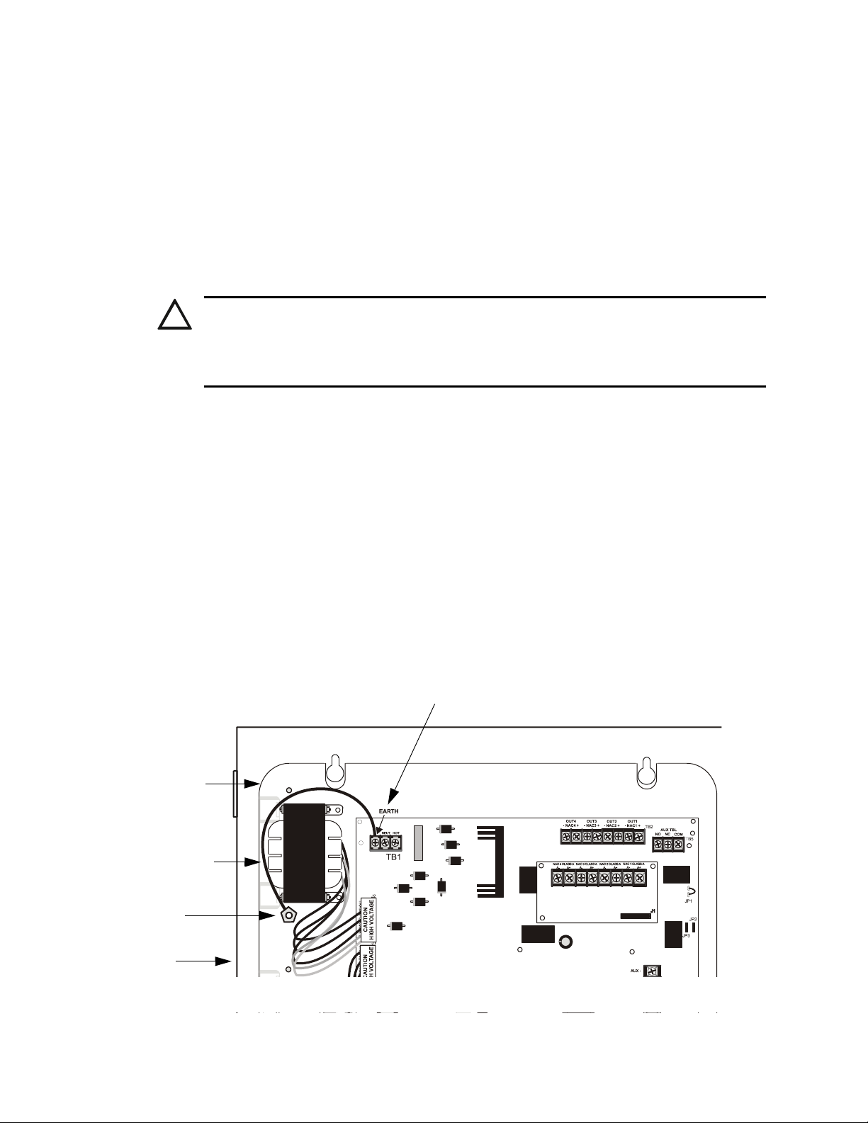
Ground Stud
Grounding Strap
Earth Terminal on TB1 (AC Terminal Block)
Backbox
Mounting Plate
24fsgrnd.wmf
Figure 2.1 Grounding Strap
Carefully unpack the system and check for shipping damage. Select a location for the cabinet that is
in a clean, dry, vibration-free area where extreme temperatures are not encountered. The area
should be readily accessible with sufficient room to easily install and maintain the power supply.
Locate the top of the cabinet approximately five feet above the floor with the hinge mounting on
the left. Determine the number of conductors required for the devices to be installed and determine
the appropriate knockouts. All wiring must be in accordance with the National and/or Local codes
for fire alarm systems and power supplies.
2.1 Backbox Mounting
CAUTION: STATIC SENSITIVE COMPONENTS
THE CIRCUIT BOARD CONTAINS STATIC-SENSITIVE COMPONENTS. ALWAYS GROUND
YOURSELF WITH A PROPER WRIST STRAP BEFORE HANDLING ANY BOARDS SO THAT
STATIC CHARGES ARE REMOVED FROM THE BODY. USE STATIC SUPPRESSIVE PACKAGING
TO PROTECT ELECTRONIC ASSEMBLIES.
1. Remove the PC board and transformers from the backbox before installing backbox. Set the
board and transformers aside in a safe, clean place. Avoid static discharge which may damage
static sensitive components on the board.
2. Mark and predrill holes for the top two keyhole mounting bolts.
3. Install two upper fasteners in the wall with the screw heads protruding approximately ¼”.
4. Using the upper keyholes, mount the backbox over the two screws.
5. Mark the lower two holes, remove the backbox from the wall and drill the mounting holes.
6. Mount the backbox, install the remaining fasteners and tighten all screws.
7. When the location is dry and free of construction dust, reinstall the PC board and transformers
and continue with the installation.
8. IMPORTANT! Make certain to connect the supplied grounding strap between the Earth
terminal on TB1 (AC Terminal Block) of the main circuit board and the chassis ground stud as
illustrated in Figure 2.1:
14 FCPS-24FS Series Instruction Manual — P/N 51883-L8:J1 8/30/13
Page 15
Backbox Mounting Installation
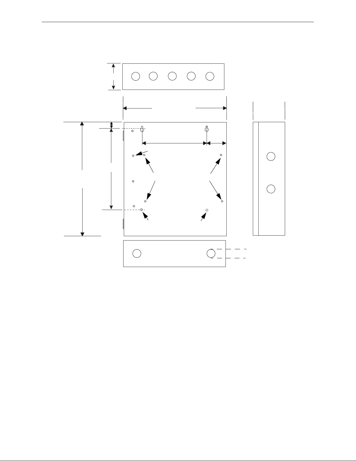
Figure 2.2 Backbox Mounting Dimensions
Bottom
Height=15.00”
(38.10 cm)
10.625”
(26.99 cm)
0.75”
(1.9 cm)
2.875” (7.3 cm)
Backbox = 14.5”
(36.8 cm)
Depth = 3.050”
(7.75 cm)
Top
9.1” (23.1 cm)
2.7”
(6.86cm)
1.125” (2.868 cm)
Mounting Plate Pem Studs
Backbox Mounting Holes
fcpscabb.wmf
Ground Stud
FCPS-24FS Series Instruction Manual — P/N 51883-L8:J1 8/30/13 15
Page 16

Installation NAC Circuit Wiring
Figure 2.3 NAC Style Y (Class B)
4.7KΩ ELR
Horn Strobe
Horn Strobe
Horn Strobe
Alarm Polarity Shown
FCPS-24FS Circuit Board
24fsclsb.wmf
Figure 2.4 Style Z (Class A) NACs using ZNAC-4 Option Module
ZNAC-4 Option Module
J3
Horn Strobes
ZNAC-4
Alarm Polarity
Shown
24fsclsa.wmf
FCPS-24FS Circuit Board
2.2 NAC Circuit Wiring
2.2.1 Style Y (Class B)
The standard configuration for NACs is Style Y (Class B) as shown in Figure 2.3.
2.2.2 ZNAC-4 Class A Option Module
The ZNAC-4 is an optional Class A conversion module which mounts to connector J3 on the upper
right side of the FCPS-24FS circuit board. This module allows the FCPS-24FS6 or FCPS-24FS8 to
support Style Z (Class A) Notification Appliance Circuits.
16 FCPS-24FS Series Instruction Manual — P/N 51883-L8:J1 8/30/13
Page 17

Addressable Module Mounting Installation
standoff
standoff
standoff
standoff
24fsmodltpH.wmf
*If the SLC device does not match the one in this figure,
refer to the SLC manual wiring conversion charts for legacy and newer versions of the modules.
Module Installation
1. Remove FCPS-24FS main circuit board from
mounting plate by removing four corner screws.
2. Install four male/female standoffs through bottom of
board in holes indicated in illustration above.
3. Screw four female/female standoffs to male ends of
standoffs installed in Step 2 to secure in place.
4. Place addressable module over standoffs installed in
Step 3 and secure with supplied screws.
5. Reinstall main circuit board on mounting plate and
wire module as show in illustration above.
Figure 2.5 Mounting Module In FCPS-24FS Cabinet
female/female standoffs
female/female standoffs
addressable module
mounting screw
24fsmodinstl.wmf
2.3 Addressable Module Mounting
The FCPS-24FS has been designed to allow the mounting of an addressable control, relay or monitor module on the main circuit board inside the power supply cabinet with the module status LED
visible through the closed door. This allows power to be fed from the FCPS-24FS Auxiliary Power
output directly to the module, if needed, without running the power wires outside the cabinet. As an
example, Figure 2.5 illustrates wiring from the Auxiliary power output terminals to a CMF-300
control module’s terminals 3 (-) and 4 (+).
NOTE: The optional module mounting kit (P/N 90286) is required to install an addressable
module on the power supply main circuit board. The kit includes four female/female and four
male/female standoffs as well as four mounting screws.
FCPS-24FS Series Instruction Manual — P/N 51883-L8:J1 8/30/13 17
Page 18

Installation NEC Power-limited (Class 2) Wiring Requirements
Figure 2.5 Power-limited (Class 2) Wiring Example
AC Power
Nonpower-limited
Output Circuits
Power-limited Circuits (Class 2)
Relay Contacts
Nonpower-limited Circuit
Input Circuits
Power-limited Circuit
(Class 2)
Specific Application
Power & SLC are
Power-limited Circuits
(Class 2)
24fspwrltpH.wmf
*If the SLC device does
not match the one in this
figure, refer to the SLC
manual wiring conversion charts for legacy
and newer versions of
the modules.
2.4 NEC Power-limited (Class 2) Wiring Requirements
Power-limited (Class 2) and nonpower-limited circuit wiring must remain separated in the cabinet.
All power-limited (Class 2) circuit wiring must remain at least 0.25” away from any nonpower-limited circuit wiring. Furthermore, all power-limited (Class 2) circuit wiring and nonpower-limited
circuit wiring must enter and exit the cabinet through different conduits. One such example of this
is shown below. Your specific application may require different conduit knockouts to be used. Any
conduit knockouts may be used. For power-limited (Class 2) applications, use of conduit is
optional.
18 FCPS-24FS Series Instruction Manual — P/N 51883-L8:J1 8/30/13
Page 19
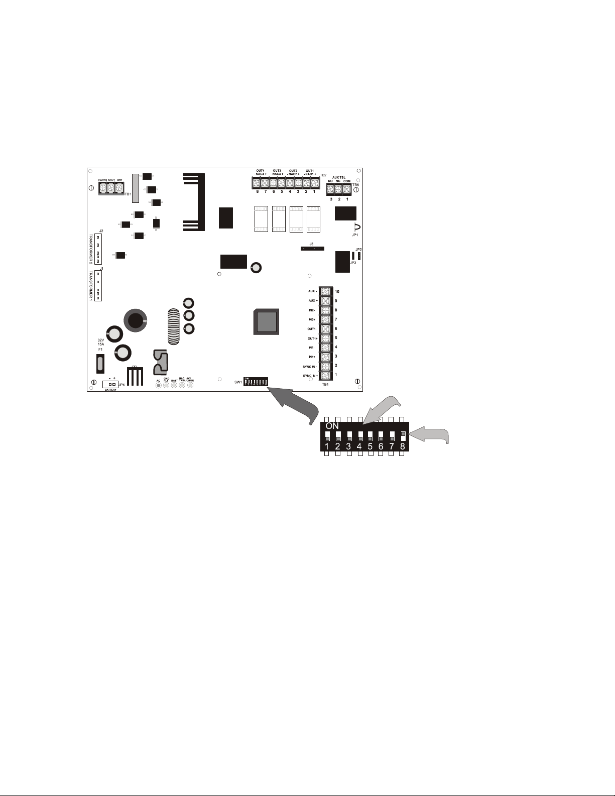
Section 3: Programming Options
Switches 1 through 7 shown
in OFF (Open) position
Switch 8 shown in
ON (Closed) position
Figure 3.1 Field Programming DIP Switches
24fsswitc.wmf
This section describes the programming options available via DIP switch settings. The FCPS can
be field programmed using option DIP switch SW1 which is located in the lower center of the circuit board. Refer to the following illustration for switch location and DIP switch placement in the
ON and OFF positions.
Important: Change DIP switch settings only when all power (AC & DC) is removed.
FCPS-24FS Series Instruction Manual — P/N 51883-L8:J1 8/30/13 19
Page 20

Programming Options DIP Switch Settings
3.1 DIP Switch Settings
The following table lists the FCPS programmable features and the switch settings required to select
a particular feature. A detailed description of each feature is presented in the following pages.
SW1 DIP Switch ON OFF
1
1 This switch works in conjunction with switch 2 to determine the Strobe Synchronization Type
2 1 OFF, 2 OFF = no sync (steady +24V) - default
3 FCPS configured for Slave Synchronization FCPS configured for Master Synchronization - default
4 Delay AC Fail Reporting for 2 Hours - default
5 This switch works in conjunction with switch 6 to determine Input to Output functions
6 5 OFF, 6 OFF = General Alarm - default
7 Disable Charger Enable Charger - default
8 Output Circuit #4 = Door Holder Output Circuit #4 = NAC - default
1 OFF, 2 ON = System Sensor
1 ON, 2 OFF = Gentex
1 ON, 2 ON = Wheelock
No Delay in AC Fail Reporting
Aux. Trouble Relay responds to all troubles
Internal Trouble contact responds to AC loss
• FCPS configured as Master (switch 3 OFF), NAC Outputs 1 through 4
Sync Input is ignored.
• FCPS configured as Slave (switch 3 ON), NAC Outputs 1 through 4
Sync Input is monitored
• Resettable or nonresettable Auxiliary Power Output is available from TB4 Terminals 9 & 10. Control Input
#2 determines if reset will occur (must go from On to Off for a minimum 6 second reset to occur).
• Output #4 function follows DIP switch 8 setting.
5 OFF, 6 ON = Split Alarm
• FCPS configured as Master (switch 3 OFF), NAC Outputs 1 & 2 are controlled by Control Input #1 and
Outputs 3 & 4
• FCPS configured as Slave
Outputs 3 & 4
• Only nonresettable Auxiliary Power is available from TB4 Terminals 9 & 10.
• Output #4 function follows DIP switch 8 setting.
5 ON, 6 OFF = Split Temporal
• FCPS configured as Master (switch 3 OFF), Control Input #1 controls NAC Outputs 1 & 2 and Control Input
#2 controls Outputs 3 & 4
• FCPS configured as Slave (switch 3 ON), Control Input #1 controls NAC Outputs 1 & 2 and Control Input #2
controls Outputs 3 & 4
for Outputs 1 & 2
• Only nonresettable Auxiliary Power is available from TB4 Terminals 9 & 10.
• Output #4 function follows DIP switch 8 setting.
5 ON, 6 ON = Selective Silence
• FCPS configured as Master (switch 3 OFF), NAC Outputs 1 through 4
Sync Input is ignored.
• Control Input #2 determines when Selective Silence for all outputs will occur
• Only nonresettable Auxiliary Power is available from TB4 Terminals 9 & 10.
• Output #4 function follows DIP switch 8 setting.
2
are controlled by Control Input #2; Sync Input is ignored.
2
are controlled by Control Input #2; Sync Input is monitored3.
3
.
4
(switch 3 ON), NAC Outputs 1 & 2 are controlled by Control Input #1 and
2
which will generate a Temporal code signal without sync; Sync Input is ignored.
2
which will generate a Temporal code signal without sync; Sync Input is monitored
3
.
Aux. Trouble Relay responds only to AC Fail/Brownout
Internal Trouble contact does not respond to AC loss
2
are controlled by Control Input #1;
2
are controlled by Control Input #1;
2
are controlled by Control Input #1;
5
.
Table 3.1 DIP Switch Settings
1 Strobe Synchronization only works with non-coded NACs.
2 If Door Closer function is selected (switch 8 ON), Output 4 does not function as an NAC, therefore sync input is
ignored for it.
3If no synchronization is selected by switches 1 & 2, the Sync Input is ignored.
4 When using Split Alarm with power supply configured for Slave Mode, System Sensor cannot be used (use
System Sensor with Master Mode only).
5 Selective Silence allows the silencing of the sounder portion of a horn/strobe combination device without turning
off the strobe.
20 FCPS-24FS Series Instruction Manual — P/N 51883-L8:J1 8/30/13
Page 21

Programmable Features Description Programming Options
3.2 Programmable Features Description
3.2.1 Synchronization Type Selection
Synchronization is a feature that controls the activation of notification appliances in such a way that
all devices will turn on and off at exactly the same time. This is particularly critical when activating strobes which must be synchronized to avoid random activation and a potential hazard or confusion. The FCPS can be programmed to operate with a variety of manufacturer’s devices. Note
that strobe synchronization works only with non-coded NACs.
DIP switches 1 and 2 are used to select the type of synchronization as listed below:
DIP Switch 1 DIP Switch 2 Synchronization Type
OFF OFF no synchronization (steady 24V)
OFF ON System Sensor
ON OFF Gentex
ON ON Wheelock
Table 3.2 Sync Type Settings
Maximum Number of Strobes for Synchronization
The total current draw for each Notification Appliance Circuit cannot exceed 3.0 amps, special
application, 300mA regulated. Refer to the manufacturer’s documentation supplied with the strobes
to determine the maximum current draw for each strobe and ensure that the circuit maximum is not
exceeded.
To ensure proper strobe and circuit operation, there is also a limit to the number of strobes that can
be attached to each circuit. Following is a table of the strobes that have been tested with the power
supply and the maximum number that can be connected to each NAC when using the lowest candela settings. Make sure that the NAC maximum current is not exceeded:
Strobe Manufacturer FCPS-24FS6 (max. strobes) FCPS-24FS8 (max. strobes)
System Sensor 51 51
Wheelock 30 40
Gentex 39 39
3.2.2 Synchronization Mode - Master/Slave
The FCPS power supply can be configured for Master or Slave Synchronization by setting DIP
switch 3 ON for Slave or OFF for Master mode.
In some installations, it is necessary to synchronize the flash timing of all strobes in the system for
ADA compliance. Strobes accomplish this by monitoring very short timing pulses on the NAC
power which are created by an FACP with synchronization capability. When installed at the end of
a NAC wire run, this power supply can track (that is follow) the strobe synchronization timing
pulses on the existing NAC wire run. This maintains the overall system flash timing of the additional strobes attached to this power supply.
When this power supply is configured as a sync generator (Master Synchronization mode), the
Sync Input terminals are not used. The power supply is the originator of the strobe synchronization
pulses on its NAC outputs. In sync generator mode, the sync type (System Sensor, Wheelock, or
Gentex) is selectable via DIP switches 1 and 2.
When this power supply is configured as a sync follower (Slave Synchronization mode), the power
supply’s NAC outputs track the strobe synchronization pulses present at the supply’s Sync Input
terminals. The pulses originate from an upstream FACP or other power supply. Some FACPs pro-
FCPS-24FS Series Instruction Manual — P/N 51883-L8:J1 8/30/13 21
Page 22

Programming Options Programmable Features Description
vide synchronization timing pulses from a dedicated sync output connector. Connect the FCPS
sync input terminals to the FACP sync output connector instead of the FACP NAC.
Note that the Synchronization Type configured by DIP switches 1 and 2 must be set to the same type
as the signal being fed to the Sync Input circuit in the event that Selective Silence is employed.
Important! In Slave Mode, if the Input is active, but no signal is present on the Sync Input circuit,
the power supply will turn the NACs on steady until a sync signal appears. The NACs will turn off
when the Input becomes inactive.
Also in Slave Mode, if the Input is active and the Sync Input is suddenly lost (FCPS or wiring failure), there will be a three second period when NAC outputs are indeterminate. After this three second period, the power supply will turn the NACs on steady until the Input becomes inactive.
3.2.3 AC Fail Delay/Aux. Trouble Relay Function
The AC Fail Delay feature provides the option to delay generation of a trouble signal upon the loss
of AC power. In addition, the operation of the Aux. Trouble Relay is altered.
• DIP switch 4 set to the ON position will delay the generation of an AC Loss/brownout trouble
signal for 2 hours. In addition, the Aux. Trouble Relay will immediately respond to all trouble
conditions on the power supply.
• DIP switch 4 set to the OFF position will allow the FCPS to generate a trouble signal
immediately on the loss of AC power. In addition, the Aux. Trouble Relay will respond only
to AC power fail/brownout conditions.
Refer to “Supervision of FCPS-24FS Faults” on page 25, for operation of internal NAC trouble
relay in response to AC loss.
3.2.4 Input/Output Function
DIP switches 5 and 6 are used to determine the Input Control circuits that will activate the four output circuits and the function of the output circuits. For example, to configure a General Alarm
operation in which Input Control Circuit #1 activates all four output NACs, DIP switches 5 and 6
are both set to the OFF position. In this configuration, the Sync Input circuit is ignored if the power
supply is set as a Master but will be monitored if the supply is set as a Slave. In addition, if the
Auxiliary Power output is set as a resettable output, the circuit connected to Control Input Circuit
#2 will control the auxiliary power reset function.
The following table details the four possible input/output configurations:
DIP Switch 5 DIP Switch 6 Input/Output Function
OFF OFF General Alarm
• FCPS configured as Master (switch 3 OFF), NAC Outputs 1 through 4
Control Input #1; Sync Input is ignored.
• FCPS configured as Slave (switch 3 ON), NAC Outputs 1 through 4
Control Input #1; Sync Input is monitored
• Resettable or nonresettable Auxiliary Power Output is available from TB4 Terminals 9 & 10.
Control Input #2 determines if reset will occur (must go from On to Off for a minimum 6
second reset to occur).
OFF ON Split Alarm
• FCPS configured as Master (switch 3 OFF), NAC Outputs 1 & 2 are controlled by Control
Input #1 and Outputs 3 & 4
• FCPS configured as Slave
Input #1 and Outputs 3 & 4
• Only nonresettable Auxiliary Power is available from TB4 Terminals 9 & 10.
1
are controlled by Control Input #2; Sync Input is ignored.
3
(switch 3 ON), NAC Outputs 1 & 2 are controlled by Control
1
are controlled by Control Input #2; Sync Input is monitored2.
2
.
1
are controlled by
2
are controlled by
Table 3.3 Input/Output Configurations
22 FCPS-24FS Series Instruction Manual — P/N 51883-L8:J1 8/30/13
Page 23

Programmable Features Description Programming Options
ON OFF Split Temporal
ON ON Selective Silence
• FCPS configured as Master (switch 3 OFF), Control Input #1 controls NAC Outputs 1 & 2
and Control Input #2 controls Outputs 3 & 4
without sync; Sync Input is ignored.
• FCPS configured as Slave (switch 3 ON), Control Input #1 controls NAC Outputs 1 & 2 and
Control Input #2 controls Outputs 3 & 4
sync; Sync Input is monitored for Outputs 1 & 2
• Only nonresettable Auxiliary Power is available from TB4 Terminals 9 & 10.
4
• FCPS configured as Master (switch 3 OFF), NAC Outputs 1 through 41 are controlled by
Control Input #1; Sync Input is ignored.
• Control Input #2 determines when Selective Silence for all outputs will occur.
• Only nonresettable Auxiliary Power is available from TB4 Terminals 9 & 10
1
which will generate a Temporal code signal
1
which will generate a Temporal code signal without
2
.
Table 3.3 Input/Output Configurations
1 If Door Closer function is selected (switch 8 ON), Output 4 does not function as an NAC, therefore sync input is
ignored for Output 4.
2If no synchronization is selected by switches 1 & 2, the Sync Input is ignored.
3 When using Split Alarm with power supply configured for Slave Mode, System Sensor cannot be used (use
System Sensor with Master Mode only).
4 Selective Silence allows the silencing of the sounder portion of a horn/strobe combination device without turning
off the strobe.
Auxiliary Power Control
The 24 VDC Auxiliary power from TB4 Terminals 9(+) & 10(-) can be resettable or nonresettable
power only when the power supply is configured for General Alarm operation. For all other configurations, the auxiliary power output is only nonresettable.
In the General Alarm configuration, the Auxiliary power output can be made resettable by applying
a steady signal to Control Input 2 (positive 12 to 24 VDC on TB4 Terminal 7 and common on Terminal 8). Temporarily removing the voltage or reversing the polarity will cause the Auxiliary
power output to reset for 6 seconds.
3.2.5 Charger Enable/Disable
The FCPS-FS battery charger can be disabled to accommodate an external battery charger. Setting
DIP switch 7 to the default setting of OFF will enable the battery charger. Setting DIP switch 7 to
the ON position will disable the charger. It should only be disabled if an external battery charger is
being used for the FCPS-FS.
3.2.6 Door Closers
Output Circuit #4 can be configured as an NAC or door closer circuit. Setting DIP switch 8 to the
OFF position will configure Output Circuit #4 as an NAC. Setting DIP switch 8 to the ON position
will configure only Output Circuit #4 as a door closer circuit which will provide a steady 24 VDC
to door holders until an alarm or AC fail condition removes the power following a 10 second delay.
FCPS-24FS Series Instruction Manual — P/N 51883-L8:J1 8/30/13 23
Page 24

Notes
24 FCPS-24FS Series Instruction Manual — P/N 51883-L8:J1 8/30/13
Page 25

Section 4: Trouble Supervision
4.1 Supervision via FACP Notification Appliance Circuit
4.1.1 Supervision of FACP to FCPS wiring
The FACP (Fire Alarm Control Panel) supervises the connection between itself and the FCPS-24FS
via the control panels NAC End-of-Line Resistor (ELR). The ELR must be installed at the FCPS
end of the circuit, after the last notification appliance on the circuit. If no additional devices are
connected from the FCPS Control Input terminals, the ELR must be connected across terminals 5
& 6 for Control Input Circuit #1 and across terminals 7 & 8 for Control Input Circuit #2. An open
or short anywhere on the control panel’s NAC or power supply NAC will be detected at the FACP
as a NAC trouble.
IMPORTANT: If additional notification appliances are connected to the Out terminals 5 & 6 of
Control Input Circuit #1 or extended from Control Input Circuit #2 Terminals 7 & 8, the ELR must
be installed after the last device on the circuit.
4.1.2 Supervision of FCPS-24FS Faults
The FACP will detect FCPS power supply faults as an open circuit condition on its NAC. An internal trouble contact is located between TB4 Terminal 3 (In+) and TB4 Terminal 5 (Out+). Any of
the following conditions will cause the trouble contact to open, provided the FACP Notification
Appliance Circuit is not in alarm. The following trouble conditions will cause a general NAC trouble:
• A field wiring fault on the NAC output of the power supply
• An AC fail condition at the power supply (only if SW1 switch 4 is ON and a 2 hour delay has
expired. If SW1 switch 4 is OFF, the Internal Trouble contact will not respond to an AC fail
condition)
• A battery fail condition at the power supply
• A battery charger fail on the power supply
• A ground fault condition on the power supply (zero impedance between power supply and
ground)
Any power supply trouble will break the connection between the FACP and the ELR connected to
Control Input #1 provided the FACP’s NAC is not in alarm. The FACP’s ELR must be placed after
the last notification appliance connected to FCPS terminals 5 & 6 on TB4 or, if no devices are connected to these terminals, the ELR must be connected directly across terminals 5 & 6.
If trouble monitoring is required when the power supply is in alarm, the Trouble Relay at TB5 can
be used for this purpose. An addressable monitor module may be used to monitor these contacts.
Refer to “Aux. Trouble Relay/AC Fail Relay” on page 25 in the following section.
NOTE: Control Input #2 (terminals 7 & 8) cannot be used to supervise the power supply for
internal troubles, but an ELR is still required for FACP wiring supervision.
4.1.3 Aux. Trouble Relay/AC Fail Relay
The FCPS-24FS power supply has one fail-safe Form-C aux. trouble relay located at TB5. The
contacts can be monitored by an FACP input circuit or an addressable monitor module as illustrated
below. The Aux. Trouble Relay responds to FCPS-24FS power supply troubles depending on the
setting of SW1 switch 4.
FCPS-24FS Series Instruction Manual — P/N 51883-L8:J1 8/30/13 25
Page 26

Trouble Supervision AC Loss Reporting Delay
SLC
Monitor Module*
Aux. Trouble Relay
Monitor Module ELR
FCPS-24FS6/8
T7
T6
NO
NC
*If the SLC device does not
match the one in this figure, refer
to the SLC manual wiring conversion charts for legacy and
newer versions of the modules.
• With SW1 switch 4 set to the ON position, AC Fail/brownout reporting will be delayed 2 hours
and the following trouble conditions will cause the normally energized Aux. Trouble Relay to
change states regardless of whether the panel is in alarm or standby:
– An AC fail condition at the power supply
– A battery fail condition at the power supply
– A battery charger fail on the power supply
– A ground fault condition on the power supply (zero impedance between the power supply
and ground
– A field wiring fault on the NAC output of the power supply. (If the panel is in alarm, only a
short circuit on the NAC will be detected as a trouble)
NOTE: The NAC Trouble LED will indicate which NAC circuit is in trouble by blinking once for
Circuit 1, twice for Circuit 2, three times for Circuit 3 and four times for Circuit 4. If more than one
circuit is in trouble, the LED will blink the highest circuit number in trouble.
• With SW1 switch 4 set to the OFF position, AC Fail/brownout reporting will occur
immediately and the Aux. Trouble Relay will change state only for AC Fail/brownout
conditions. A monitor module can be used to monitor the relay for AC fail.
4.2 AC Loss Reporting Delay
The reporting of AC loss to a central station is usually delayed in order to prevent multiple transmissions of AC loss and restoral, thus allowing AC power to stabilize. When a host FACP is programmed to delay AC loss reporting, the FCPS-24FS must be configured to delay the reporting of
AC fail. This is accomplished by setting SW1 DIP switch 4 to the ON position. This will prevent
AC loss from being reported as a trouble condition for two hours.
Changing the AC Loss Reporting setting will also affect the functioning of the Trouble Relay.
Refer to “Aux. Trouble Relay/AC Fail Relay” on page 25.
Note that the FCPS-24FS power supply will immediately indicate loss of AC power by turning off
the AC Power LED and turning on the Charger Trouble/AC Loss LED, regardless of the setting of
SW1 DIP switch 4.
26 FCPS-24FS Series Instruction Manual — P/N 51883-L8:J1 8/30/13
Page 27

Section 5: Applications
5.1 Controlling Four NACs With One Input and Selective Silence
NOTE: The Relay Module is required only for this application with the power supply set as Master.
If the power supply is set as Slave, the Relay Module is not required. In Slave mode, selective
silence (horn mute) is provided by the FACP through the sync input.
In this application, the power supply has been set as a master with synchronized outputs and selective silence (see SW1 switch settings in following illustration). All four FCPS-24FS output circuits,
which are shown as NACs (Notification Appliance Circuits), can be controlled from one input such
as an addressable control module as illustrated in Figure 5.1. The control module can be powered
from the FCPS-24FS auxiliary 24 VDC power output (TB4, Terminals 9 & 10) and supervised by
an EOL relay. An addressable relay module, programmed as an alarm output and a silenceable
point, can be used as a selective silence input.
NOTE: Mass Notification (MN) only, Fire only, or MN/Fire combo NACs only are
allowed.
FCPS-24FS Series Instruction Manual — P/N 51883-L8:J1 8/30/13 27
Page 28
Applications Controlling Four NACs With One Input and Selective Silence
Figure 5.1 Controlling Four Outputs With One Input
Control Module*
Relay Module*
EOL Power
Supervision Relay
EOLR-1
(energized)
SLC
SLC
Style Z (Class A)
Style Y (Class B)
Use listed ELR
(4.7KΩ) to terminate
Style Y (Class B)
NAC
Note: All NACs are supervised and power-limited (Class 2)
ZNAC-4
Option Module
Output/NAC 4
Output/NAC 3
Output/NAC 2
Output/NAC 1
FCPS-24FS has been set for
Selective Silence and Relay
Module has been programmed
at FACP as a silenceable point
so it can perform selective
silence when its Normally Open
contact (8 & 10) closes in
alarm, then opens when silence
is invoked at the FACP.
Note: the Relay Module can be
mounted on the power supply
inside the cabinet. This allows
power wiring to remain inside
the cabinet.
SW1 Switch Settings
1 & 2 = sync (any setting but OFF/OFF)
3 = OFF (master)
4 = OFF (no AC Fail reporting delay)
5 = ON
6 = ON
7 = OFF (charger enabled)
8 = OFF (circuit 4 NAC function)
(selective silence)
End-of-Line Resistor
supplied with Control
Module
Internal Trouble Contact
ELR not required for
Style Z (Class A) NAC
FCPS-24FS
Horn/Strobes
Alarm Polarity Shown
Horn/Strobes
Alarm Polarity Shown
24fsapp7tpH.wmf
*If the SLC device does not match the one in this figure,
refer to the SLC manual wiring conversion charts for
legacy and newer versions of the modules.
T11
T10
T9
T8
T7
T6
T11
T10
T9
T8
T7
T6
T1
T2
T3
T4
T5
T1
T2
T3
T4
T5
The control module is shown to demonstrate the use of a remotely mounted device associated with
an addressable fire alarm control panel. The module could be replaced with any circuit capable of
polarity reversal, such as an FACP NAC.
The following notes apply to Figure 5.1 on page 28.
1. When the FCPS-24FS power supply is in an inactive state (control module not active), a
trouble on the power supply will result in an open circuit condition on the control module
output circuit (monitored by End-of-Line Resistor across TB4, Terminals 5 & 6). As an
alternative, the trouble contacts at TB5 of the power supply can also be used for independent
trouble monitoring.
2. The addressable relay module must be programmed as a silenceable point at the FACP to allow
selective silence of horn/strobe devices. The Normally Open contact of the relay module is
connected between TB4 Terminal 7 (IN2 +) and Terminal 9 (Aux. Power +).
3. Do not loop wires under screw terminals. Break wires to maintain proper supervision.
4. An End-of-Line Resistor must be installed between TB4, Terminals 5 & 6 for control module
wiring supervision (the ELR value is dependent on the module employed).
28 FCPS-24FS Series Instruction Manual — P/N 51883-L8:J1 8/30/13
Page 29

Controlling Three NACs and One Door Holder With One Input Applications
TB4
1 2 3 4 5 6 7 8 9 10
SYNC SYNC IN+ IN- OUT+ OUT- IN2+ IN2- AUX+ AUX-
5. Supervise the power wiring between the FCPS-24FS auxiliary 24 VDC output on TB4,
Terminals 9 & 10 with an EOL relay (P/N: EOLR-1).
6. For a list of compatible devices, refer to the Fire•Lite Device Compatibility Document #15384.
7. IMPORTANT! When the power supply is programmed for both Selective Silence and Slave
Mode, TB4 Terminal 7 (IN+) must be jumpered to Terminal 9 (AUX+) and Terminal 8 (IN-)
must be jumpered to Terminal 10 (AUX-). The FACP will control the Selective Silence feature
with this configuration.
If the terminals are not jumpered as indicated, the horn portion of the horn/strobes will be
silenced
at all times.
5.2 Controlling Three NACs and One Door Holder With One Input
In this application, the power supply has been set as a master with synchronized outputs. All four
FCPS-24FS output circuits, three NACs and one door holder, can be controlled from one input such
as an addressable control module as illustrated in Figure 5.2. The control module can be powered
from the FCPS-24FS auxiliary 24 VDC power output (TB4, Terminals 9 & 10).
FCPS-24FS Series Instruction Manual — P/N 51883-L8:J1 8/30/13 29
Page 30

Applications Controlling Three NACs and One Door Holder With One Input
Figure 5.2 Controlling Three NACs and One Door Holder With One Input
Style Z (Class A)
Style Y (Class B)
Door Holder Circuit 4
Output/NAC 3
Output/NAC 2
Output/NAC 1
Use listed ELR
(4.7KΩ) to
terminate Style Y
(Class B) NAC
ELR not required for
Style Z (Class A) NAC
Door Holder
Door Holder
Note: All NACs are supervised and power-limited (Class 2)
ZNAC-4
Option Module
SW1 Switch Settings
1 & 2 = sync (any setting but OFF/OFF)
3 = OFF (master)
4 = OFF (no AC Fail reporting delay)
5 = OFF
6 = OFF
7 = OFF (charger enabled)
8 = ON (circuit 4 door holder)
Internal Trouble Contact
(general alarm)
Control Module*
SLC
End-of-Line Resistor
supplied with Control
Module
FCPS-24FS
Horn/Strobes
Alarm Polarity
Shown
Horn/Strobes
Alarm Polarity
Shown
24fsapp6tpH.wmf
*If the SLC device does not match the one in this
figure, refer to the SLC manual wiring conversion
charts for legacy and newer versions of the modules.
The control module is shown to demonstrate the use of a remotely mounted device associated with
an addressable fire alarm control panel. The module could be replaced with any circuit capable of
polarity reversal, such as an FACP Notification Appliance Circuit.
The following notes apply to Figure 5.2 on page 30.
1. The Output 4 door holder circuit will deactivate 10 seconds after Control Input #1 is activated
2. When the FCPS-24FS power supply is in an inactive state (control module not active), a
3. Do not loop wires under screw terminals. Break wires to maintain proper supervision.
or AC power is lost.
trouble on the power supply will result in an open circuit condition on the control module
output circuit (monitored by an End-of-Line Resistor across Terminals 5 & 6). As an
alternative, the trouble contacts at TB5 of the power supply can also be used for independent
trouble monitoring.
30 FCPS-24FS Series Instruction Manual — P/N 51883-L8:J1 8/30/13
Page 31

Split Temporal Mode of Operation Applications
4. An End-of-Line Resistor must be installed between terminals 5 & 6 for control module wiring
supervision (the ELR value is dependent on the module employed).
5. For a list of compatible devices, refer to the Fire•Lite Device Compatibility Document #15384.
5.3 Split Temporal Mode of Operation
In this application, the power supply has been set as a master with two synchronized and two nonsynchronized outputs as determined by the Split Temporal mode feature. Control Input #1 (TB4,
Terminals 3 & 4) is connected to an addressable control module which will cause the synchronized
FCPS-24FS Series Instruction Manual — P/N 51883-L8:J1 8/30/13 31
Page 32
Applications Split Temporal Mode of Operation
TB4
JP3
J3
TB5
TB2
JP1
JP2
OUT4
-NAC4+
OUT4
-NAC4+
OUT4
-NAC4+
OUT3
-NAC3+
OUT2
-NAC2+
OUT1
-NAC1+
AUX -
IN2-
IN2+
OUT1-
OUT1+
IN1-
IN1+
SYNC IN -
SYNC IN +
AUX +
NO N C
AUX TBL
COM
1 2 3 4 5 6 7 8 9 10
8
7
6
5
4
3
2
1
8
7
8
7
TB2
TB2
3
2
1
+
+++
+
+
+++
-
-------
-
T1
T11
T2
T10
T3
T9
T4
T8
T5
T7
T6
Figure 5.3 Split Temporal Mode Application
Style Z (Class A)
Style Y (Class B)
Temporal Bell Circuit 4
Temporal Bell Circuit 3
Horn/Strobe Circuit 2
Horn/Strobe Circuit 1
Use listed ELR
(4.7KΩ) to
terminate Style Y
(Class B) NAC
ELR not required for
Style Z (Class A) NAC
Note: All NACs are supervised and power-limited (Class 2)
ZNAC-4
Option Module
SW1 Switch Settings
1 & 2 = sync (any setting but
OFF/OFF)
3 = OFF (master)
4 = OFF (no AC Fail reporting delay)
5 = ON
6 = OFF
7 = OFF (charger enabled)
8 = OFF (circuit 4 NAC)
Internal Trouble Contact
Split Temporal
FACP
Control Module*
End-of-Line
Resistor supplied
with Control Module
FACP NAC
End-of-Line
Resistor
Bells
Bells
SLC
24fsapp5tpH2.wmf
*If the SLC device does not match the one in this
figure, refer to the SLC manual wiring conversion
charts for legacy and newer versions of the modules.
T11
T10
T9
T8
T7
T6
T1
T2
T3
T4
T5
FCPS-24FS
NAC
(steady,
no sync)
power supply output circuits 1 & 2 to turn on. Control Input #2 (TB4, Terminals 7 & 8) is connected to an FACP Notification Appliance Circuit which is used to activate the power supply’s temporal output circuits 3 & 4.
32 FCPS-24FS Series Instruction Manual — P/N 51883-L8:J1 8/30/13
Page 33

Remote Supply With Resettable and Nonresettable Power Applications
The following notes apply to Figure 5.3 on page 32.
1. When the FCPS-24FS power supply is in an inactive state (control module not active), a
trouble on the power supply will result in an open circuit condition on the control module
output circuit (monitored by an End-of-Line Resistor across Terminals 5 & 6). As an
alternative, the trouble contacts at TB5 of the power supply can also be used for independent
trouble monitoring.
2. Do not loop wires under screw terminals. Break wires to maintain proper supervision.
3. An End-of-Line Resistor must be installed between terminals 5 & 6 for control module wiring
supervision (the ELR value is dependent on the module employed) and across terminals 7 & 8
for FACP NAC wiring supervision (the ELR value is dependent on the NAC).
4. For a list of compatible devices, refer to the Device Compatibility Document.
5.4 Remote Supply With Resettable and Nonresettable Power
The FCPS-24FS can be used as a remote stand-alone power supply to provide power to any devices
that require filtered, resettable or nonresettable power. The FCPS-24FS6 can provide up to 4 amps
of continuous current and the FCPS-24FS8 can provide up to 6 amps of continuous current. The
power supply must be set for Split Alarm mode. Output circuits 1 & 2 are configured as resettable
power outputs by connecting the resettable power from an FACP to Control Input 1 Terminals 3(+)
& 4(-) on TB4 of the FCPS-24FS. Output circuits 3 & 4 are configured as nonresettable power outputs by connecting jumpers between the auxiliary 24 VDC output on TB4 to the Control Input 2
terminals on TB4 [Terminals 9(+) to 7(+) and 10(-) to 8(-)].
NOTE: All four outputs can be configured as resettable or all four can be configured as
nonresettable by setting the power supply for General Alarm and then connecting a resettable
power source to Control Input 1 or a nonresettable power source, such as the Aux. Power output
of the FCPS-24FS, to Control Input 1.
FCPS-24FS Series Instruction Manual — P/N 51883-L8:J1 8/30/13 33
Page 34

Applications Remote Supply With Resettable and Nonresettable Power
Figure 5.4 Remote Power Supply Application
Power Output 1
Resettable
Power Output 2
Resettable
Power Output 3
Nonresettable
Power Output 4
Nonresettable
SLC
SLC
Monitor Module*
FACP
24 VDC
Resettable
Power
FCPS-24FS
EOL Power
Supervision
Relay
EOLR-1
(energized)
SW1 Switch Settings
1 = OFF
2 = OFF
3 = OFF (master)
4 = ON (Aux Trouble Relay responds
to all troubles)
5 = OFF
6 = ON
7 = OFF (charger enabled)
8 = OFF (circuit 4 NAC)
Split Alarm
No Sync
End-of-Line Resistor supplied
with Monitor Module
24fsapp4tpH.wmf
*If the SLC device does
not match the one in this
figure, refer to the SLC
manual wiring conversion
charts for legacy and newer
versions of the modules.
T11
T10
T9
T8
T7
T6
T1
T2
T3
T4
T5
For addressable panel applications, an addressable monitor module can be used to monitor the trouble contact of the FCPS-24FS and the resettable power connection from the FACP using an End-ofLine power supervision relay. If the FCPS-24FS enters a trouble condition, the Normally Closed
trouble contact will open and if the resettable power from the FACP is lost, the Normally Closed
power supervision relay contact will open.
The following notes apply to Figure 5.4 on page 34.
1. An End-of-Line Resistor must be installed between TB5, Terminal 1 (trouble relay common)
and the monitor module input circuit for module wiring supervision (the ELR value is
dependent on the module employed).
2. An End-of-Line power supervision relay must be connected between TB4, Terminals 5 & 6.
The Normally Closed (when energized) power supervision relay contact must be in series with
the End-of-Line Resistor referred to in note 1.
3. Do not loop wires under screw terminals. Break wires to maintain proper supervision.
4. For a list of compatible devices, refer to the Fire•Lite Device Compatibility Document #15384.
34 FCPS-24FS Series Instruction Manual — P/N 51883-L8:J1 8/30/13
Page 35
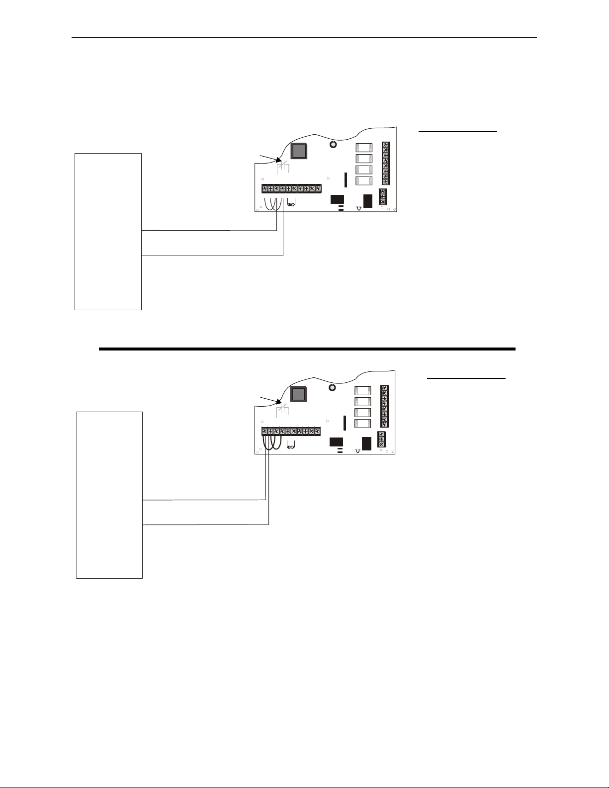
Master FACP with Slave FCPS-24FS Power Supply Applications
-
+
TB4
JP3
J3
TB5
TB2
JP1
JP2
OUT4
-NAC4+
OUT3
-NAC3+
OUT2
-NAC2+
OUT1
-NAC1+
AUX -
IN2-
IN2+
OUT1-
OUT1+
IN1-
IN1+
SYNC IN -
SYNC IN +
AUX +
NO NC
AUX TBL
COM
1 2 3 4 5 6 7 8 9 10
8
7
6
5
4
3
2
1
3
2
1
ELR
-
+
TB4
JP3
J3
TB5
TB2
JP1
JP2
OUT4
-NAC4+
OUT3
-NAC3+
OUT2
-NAC2+
OUT1
-NAC1+
AUX -
IN2-
IN2+
OUT1-
OUT1+
IN1-
IN1+
SYNC IN -
SYNC IN +
AUX +
NO NC
AUX TBL
COM
1 2 3 4 5 6 7 8 9 10
8
7
6
5
4
3
2
1
3
2
1
ELR
Standby Polarity Shown
FCPS-24FS
SW1 Switch Settings
1 & 2 = sync (any setting
but OFF/OFF)
3 = ON (slave)
4 = OFF (no AC Fail
reporting delay)
5 = OFF
6 = OFF
7 = OFF (charger enabled)
8 = OFF (circuit 4 NAC)
Figure 5.5 Supervised Master/Slave Connections
general alarm
24fsapp1c.wmf
See Note 3
24fsapp1b.wmf
SW1 Switch Settings
1 & 2 = sync (any setting
but OFF/OFF)
3 = ON (slave)
4 = OFF (no AC Fail
reporting delay)
5 = OFF
6 = OFF
7 = OFF (charger enabled)
8 = OFF (circuit 4 NAC)
Figure 5.5a: Supervised Master/Slave Connections (Filtered, Synchronized NAC Source)
Figure 5.5b: Supervised Master/Slave Connections (Remote Sync Source)
Standby Polarity Shown
FACP
NAC1
(programmed
for sync)
Internal Trouble
Contact
FACP
Remote Sync
Output
Internal Trouble
Contact
5.5 Master FACP with Slave FCPS-24FS Power Supply
In this application, an FCPS-24FS power supply, configured as a Slave unit, is connected to a master FACP programmed for synchronized output. The power supply should be set for synchronization which matches the FACP programming.
The following notes apply to both illustrations in Figure 5.5 on page 35
1. Refer to NFPA 72, Chapter 4-4, Visible Characteristics, Public Mode.
2. Use only devices from the same manufacturer in each system.
3. If the FACP has a dedicated sync output connector, wire the remote sync output connector to
the FCPS Sync In terminals TB4 terminals 1 & 2. Refer to the Supervised Master/Slave
Connections (Remote Sync Source) in Figure 5.5b.
FCPS-24FS Series Instruction Manual — P/N 51883-L8:J1 8/30/13 35
Page 36
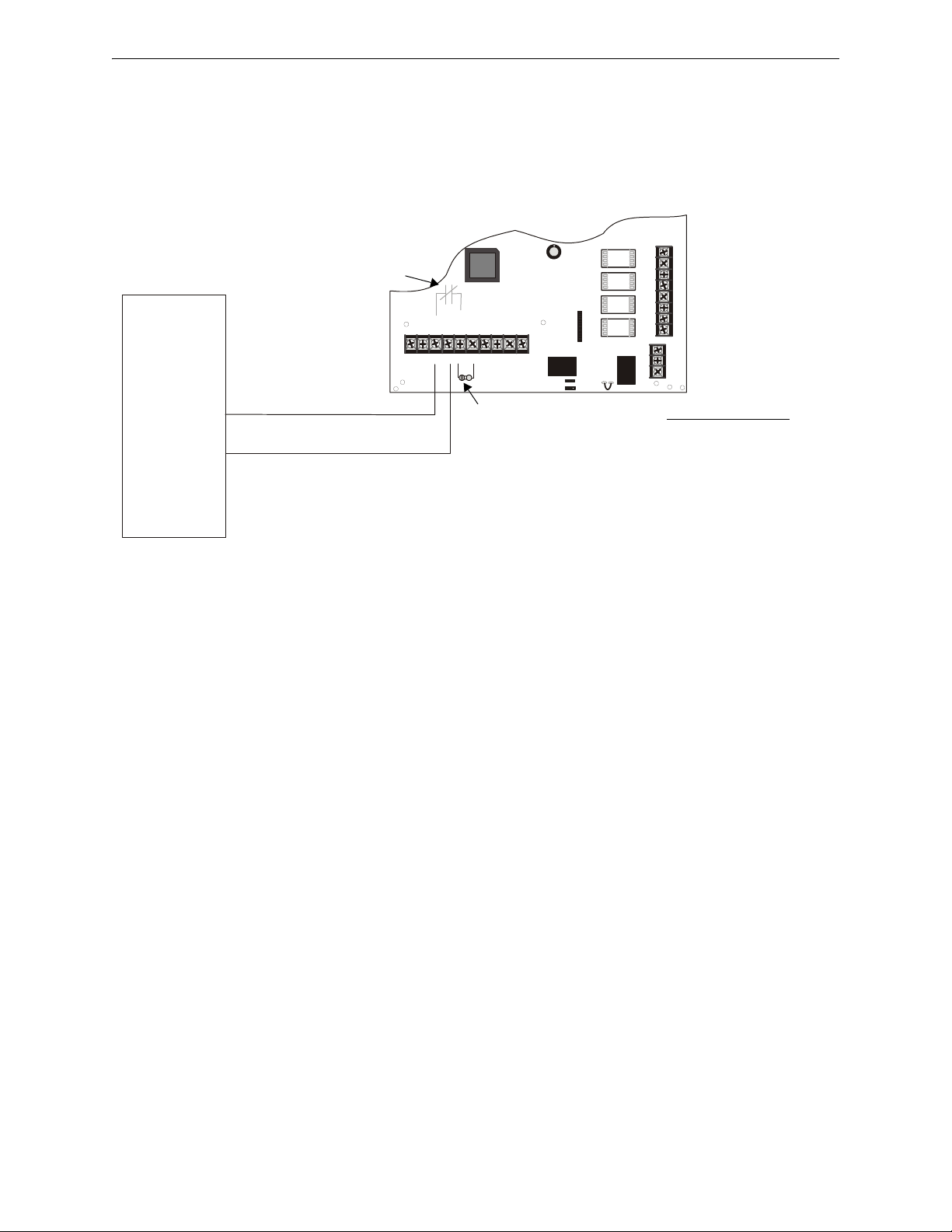
Applications Master FCPS-24FS Power Supply Connected to FACP
-
+
TB4
JP3
J3
TB5
TB2
JP1
JP2
OUT4
-NAC4+
OUT3
-NAC3+
OUT2
-NAC2+
OUT1
-NAC1+
AUX -
IN2-
IN2+
OUT1-
OUT1+
IN1-
IN1+
SYNC IN -
SYNC IN +
AUX +
NO NC
AUX TBL
COM
1 2 3 4 5 6 7 8 9 10
8
7
6
5
4
3
2
1
3
2
1
Standby Polarity Shown
FCPS-24FS
SW1 Switch Settings
1 & 2 = sync (any setting
but OFF/OFF)
3 = OFF (master)
4 = OFF (No AC Fail
Reporting Delay)
5 = OFF
6 = OFF
7 = OFF (charger enabled)
8 = OFF (circuit 4 NAC)
Figure 5.6 Supervised FACP to Master Connections (nonsynchronized source)
general alarm
24fsapp11b.wmf
FACP
NAC with no
syncronization
NAC1
Internal Trouble
Contact
ELR for
FACP
NAC
5.6 Master FCPS-24FS Power Supply Connected to FACP
In this application, a master FCPS-24FS power supply, set for synchronization, is connected to an
FACP with nonsynchronized output.
5.7 Canadian Applications
The following notes apply to this illustration
1. Refer to NFPA 72, Chapter 4-4, Visible Characteristics, Public Mode.
2. Use only devices from the same manufacturer in each system.
Canadian applications, per ULC, require the following:
• The FCPS-24FS power supply must be used as a Notification Appliance Circuit extender only.
The TB2 terminals cannot be configured as auxiliary power outputs.
• The host FACP must monitor for all ground fault conditions. The Ground Fault Detection
circuit on the FCPS-24FS power supply must be disabled by cutting jumper JP1.
36 FCPS-24FS Series Instruction Manual — P/N 51883-L8:J1 8/30/13
Page 37
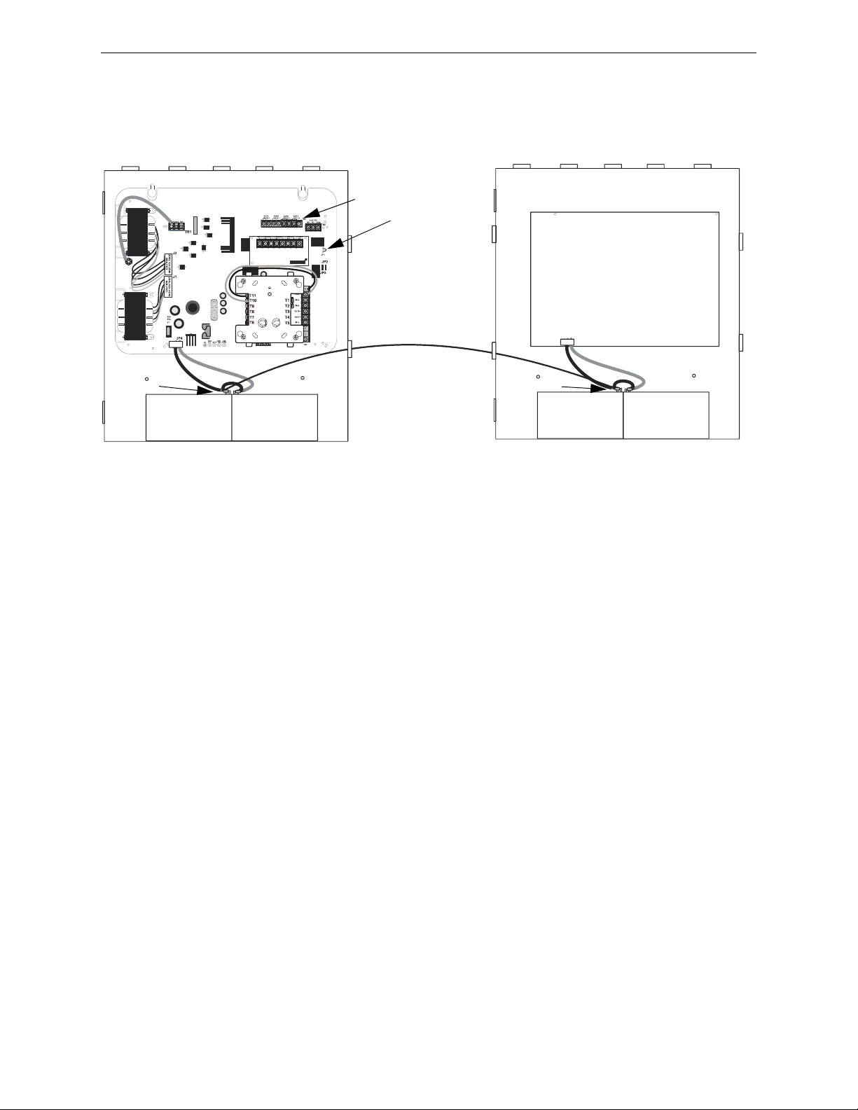
Canadian Applications Applications
Host FACP
FCPS Power Supply
Battery -
Battery -
NAC Outputs only
Cut JP1
24fsCanadiantpH.wmf
*If the SLC device does not match the one in this figure, refer to the SLC manual wiring conversion charts for legacy and newer versions of the modules.
• The negative (-) battery terminal of the FCPS-24FS power supply must be connected to the
negative (-) battery terminal of the host FACP.
FCPS-24FS Series Instruction Manual — P/N 51883-L8:J1 8/30/13 37
Page 38

Section 6: Power Supply Requirements
6.1 Overview
This section contains instructions and tables for calculating power supply currents in alarm and
standby conditions. This is a four-step process, consisting of the following:
1. Calculating the total amount of AC branch circuit current required to operate the system
2. Calculating the power supply load current for non-fire and fire alarm conditions and
calculating the secondary (battery) load
3. Calculating the size of batteries required to support the system if an AC power loss occurs
4. Selecting the proper batteries for your system
6.2 Calculating the AC Branch Circuit
The power supply requires connection to a separate, dedicated AC branch circuit, which must be
labeled FIRE ALARM. This branch circuit must connect to the line side of the main power feed
of the protected premises. No other non-fire alarm equipment may be powered from the fire alarm
branch circuit. The branch circuit wire must run continuously, without any disconnect devices,
from the power source to the power supply. Overcurrent protection for this circuit must comply
with Article 760 of the National Electrical Codes as well as local codes. Use 14 AWG (2.00 mm
wire with 600 volt insulation for this branch circuit.
Use Table 6.1 to determine the total amount of current, in AC amperes, that must be supplied to the
system.
2
)
Device Type
FCPS-24FS6/8(C)
or
FCPS-24FS6/8E
[ ] [ ] x [ ] =
[ ] [ ] x [ ] =
Number of
Devices
1x
Sum Column for AC Branch Current Required
Current Draw
(AC amps)
3.2
or
1.6
Table 6.1 120/240 VAC Branch Circuit Requirements
Total Current
per Device
=
=
38 FCPS-24FS Series Instruction Manual — P/N 51883-L8:J1 8/30/13
Page 39

Calculating the System Current Draw Power Supply Requirements
6.3 Calculating the System Current Draw
6.3.1 Overview
The power supply must be able to power all internal and external devices continuously during the
non-fire alarm condition. To calculate the non-fire alarm load on the power supply when primary
power is applied, use Calculation Column 1 in Table 6.3 on page 40. The power supply must support a larger load current during a fire alarm condition. To calculate the fire alarm load on the
power supply, use Calculation Column 2 in Table 6.3 on page 40. The secondary power source
(batteries) must be able to power the system during a primary power loss. To calculate the non-fire
alarm load on the secondary power source, use Calculation Column 3 in Table 6.3 on page 40.
When calculating current draw and the battery size, note the following:
• Primary refers to the main power source for the power supply.
• Secondary refers to the power supply’s backup batteries.
• All currents are given in amperes (A). Table 6.2 shows how to convert milliamperes and
microamperes to full amperes.
To convert... Multiply Example
Milliamperes (mA) to
amperes (A)
Microamperes (μA) to
amperes (A)
mA x 0.001 3 mA x 0.001 = 0.003 A
μA x 0.000001 300 μA x 0.000001 = 0.0003 A
Table 6.2 Converting to Full Amperes
6.3.2 How to Calculate System Current Draw
Use Table 6.3 on page 40 to calculate current draws as follows:
1. Enter the quantity of devices in all three columns.
2. Enter the current draw where required. Refer to the Fire-Lite Device Compatibility Document
for compatible devices and their current draws.
3. Calculate the current draws for each in all columns.
4. Sum the total current for each column.
5. Copy the totals from Column 2 and Column 3 to Table 6.3 on page 40.
Following are the types of current that can be entered into Table 6.3 on page 40.
Calculation Column 1 - The primary supply current load that the power supply must
support during a non-fire alarm condition, with AC power applied
Calculation Column 2 - The primary supply current load the power supply must support
during a fire alarm condition, with AC power applied
Calculation Column 3 - The standby current drawn from the batteries in a non-fire alarm
condition during a loss of AC power
FCPS-24FS Series Instruction Manual — P/N 51883-L8:J1 8/30/13 39
Page 40

Power Supply Requirements Calculating the System Current Draw
Table 6.3 contains three columns for calculating current draws. For each column, calculate the current and enter the total (in amperes) in the bottom row. When finished, copy the totals from Calculation Column 2 and Calculation Column 3 to Table 6.4 on page 41.
Calculate Column 1
Device Type
Main Circuit
Board
Power
Supervision Relay
NAC/Output #1
NAC/Output #2 [ ] X [ ] =
NAC/Output #3 [ ] X [ ] =
NAC/Output #4 [ ] X [ ] =
Current Draw
from TB4
Terminals 9 & 10
Sum each
column for totals
Primary, Non-Fire Alarm Current
(amps)
Qty X (current draw) = Total Qty X (current draw) = Total Qty X (current draw) = Total
1 X [ 0.091] = 1 X [ 0.145] = 1 X [ 0.065] =
[ ] X [ 0.025] = [ ] X [0.025 ] = [ ] X [ 0.025] =
[ ] = [ ] = [ ] =
Primary Non-Alarm = Primary Alarm = Secondary Alarm =
Calculate Column 2
Primary, Fire Alarm Current
(amps)
[ ] X [ ] =
Table 6.3 System Current Draw Calculations
Calculation Column 3
Secondary, Non-Fire Alarm
Current
(amps)
40 FCPS-24FS Series Instruction Manual — P/N 51883-L8:J1 8/30/13
Page 41

Calculating the Battery Size Power Supply Requirements
6.4 Calculating the Battery Size
Use Table 6.4 to calculate the total Standby and Alarm load in ampere hours (AH). This total load
determines the battery size (in AH) required to support the power supply under the loss of AC
power. Complete Table 6.4 as follows:
1. Enter the totals from Table 6.3 on page 40, Calculation Columns 2 and 3 where shown.
2. Enter the NFPA Standby and Alarm times. Refer to Section 6.4.1, “NFPA Battery
Requirements”.
3. Calculate the ampere hours for Standby and Alarm, then sum the Standby and Alarm ampere
hours.
4. Multiply the sum by the derating factor of 1.2 to calculate the proper battery size (in AH).
5. Write the ampere hour requirements on the Protected Premises label located inside the cabinet
door.
Secondary Standby Load
(total from Table 6.3 Calculation
Column 3)
[ ]
Primary Alarm Load
(total from Table 6.3 Calculation
Column 2)
[ ]
Sum of Standby and Alarm Ampere Hours = AH
for nonULC applications, multiply by the Derating Factor
for ULC applications, multiply by the Derating Factor
Battery Size, Total Ampere Hours Required = AH
Required Standby Time
(24 or 60 hours)
X [ ]
Required Alarm Time
(for 5 min., enter 0.084,
for 10 min., enter 0.168)
X [
Table 6.4 Total Secondary Power Requirements at 24 VDC
1 Multiply by only one of the Derating Factors, depending on whether the power
supply is being used for a ULC (Canadian) application or nonULC application.
6.4.1 NFPA Battery Requirements
NFPA 72 Local and Proprietary Fire Alarm Systems require 24 hours of standby power followed by
5 minutes in alarm.
6.4.2 Selecting and Locating Batteries
=AH
=AH
1
1
X 1.2
X 2.5
Select batteries that meet or exceed the total ampere hours calculated in Table 6.4. The power supply can charge batteries in the 7 AH to 18 AH range. The power supply cabinet is capable of housing batteries up to 7 AH. Batteries larger than 7 AH require the BB-17F or other UL listed external
battery cabinet.
FCPS-24FS Series Instruction Manual — P/N 51883-L8:J1 8/30/13 41
Page 42

Notes
42 FCPS-24FS Series Instruction Manual — P/N 51883-L8:J1 8/30/13
Page 43

Appendix A: Wire Requirements
Connecting external system accessories to the main circuits must be carefully considered to ensure
proper operation. It is important to use the correct type of wire, gauge and run length for each circuit. The following table lists NAC wiring requirements for the FCPS-24FS6 and FCPS-24FS8
Field Charger Power Supply.
Max.
NAC Load
(Amps)
allowable
total loop
resistance
(ohms)
0.25 6.00 1554 977 613 386 777 489 307 193
0.5 3.00 777 489 307 193 389 244 153 97
0.75 2.00 518 326 204 129 259 163 102 64
1.0 1.50 389 244 153 97 194 122 77 48
1.25 1.20 311 195 123 77 155 98 61 39
1.5 1.00 259 163 102 64 130 81 51 32
1.75 0.86 222 140 88 55 111 70 44 28
2.0 0.75 194 122 77 48 97 61 38 24
2.25 0.67 173 109 68 43 86 54 34 21
2.5 0.60 155 98 61 39 78 49 31 19
2.75 0.55 141 89 56 35 71 44 28 18
3.0 0.50 130 81 51 32 65 41 26 16
Max. allowable wire pair lenth
AWG 12
solid
CLASS-B
AWG 14
solid
(feet)
AWG 16
solid
AWG 18
solid
Max. allowable wire pair length
AWG 12
solid
CLASS-A
AWG 14
solid
(feet)
AWG 16
solid
Table A.1 NAC Wiring Requirements for Power Supply
NOTE: Calculations are based on Direct-Current Resistance data for uncoated copper wire, per
National Electrical Code (2005 Edition) Table 8, Conductor Properties.
AWG 18
solid
NOTE: These distances reflect the worst case scenario and are based on the correct draw of the
highest candela strobes at the low end of the supported NAC voltage with the entire load at the
end of the circuit. Further distances can be achieved by performing a point to point voltage
calculation that more accurately reflects the specific devices used and how they are dispersed on
the circuit.
FCPS-24FS Series Instruction Manual — P/N 51883-L8:J1 8/30/13 43
Page 44

Index
A
AC
Loss
8
Loss Reporting Delay
AC fail
delay
22
see also AC loss reporting delay
AC loss
reporting delay
AC loss reporting
delay
9
AC power
activation
alarm condition
applications
Auxiliary Power
Auxiliary Power Control
10
current
10
LED
10
voltage
10
reverse polarity
8
8
9, 11
current
11
voltage
11
see also resettable or nonresettable power
23
26
22
8
22
Class A Converter Module
see also ZNAC-4
Class B
see also Style Y
Coded Input
Coded/Noncoded Input Selection
coding
compatibility
control circuit
current
10
NAC
8
input circuit
8
8
current
11
see also input circuit
voltage
11
maximum continuous
maximum short term
standby
total continuous
total short term
11
16
8
8
11
9
9
11
11
D
dimensions
backbox
15
10
B
backbox dimensions 15
battery
capacity
charge current
charger capacity
float charge voltage
fuse F1
lead acid
maximum capacity
see also secondary power
trouble
battery/charger trouble LED
11
11
9
11
11
9, 11
9
8
C
cabinet
see also backbox
capacity
battery
11
charge current
maximum
charger trouble
LED
10
circuit board
layout
12
15
11
8
10
11
E
ELR
installation
see also End-of-Line Resistor
End-of-Line Resistor
see also ELR
25
25
F
faults 25
FCPS-24FS6
FCPS-24FS8
Features
filtered power
float charge voltage
Form-C
see also Relay
8
8
8
8
11
9
G
ground fault 8
ground fault detection
Jumper JP1
ground fault LED
9, 10
10
10
I
input
25
44 FCPS-24FS Series Instruction Manual — P/N 51883-L8:J1 8/30/13
Page 45

Index J–T
current 11
voltage
11
input circuit
installation
8
activation
compatibility
see also control
8
8
14
11
J
JP1 Jumper
ground fault detection
JP2 Jumper
Coded/Noncoded Input
JP3 Jumper
Coded/Noncoded Input
Jumper
JP1 ground fault detection
JP2 Coded/NonCoded Input
JP3 Coded/Noncoded Input
10
10
10
9, 10
10
10
L
LED
AC power
battery/charger trouble
Charger Trouble
Ground Fault
NAC Trouble
LED indicators
10
10
10
10
10
10
M
mounting
see also installation
14
N
NAC
activation
coding
see also Notification Appliance Circuit
supervision
NAC Circuit Wiring
NAC output
see also output circuit
NAC style
see alsoNFPA Style
NAC Trouble LED
NACs
9
NEC power-limited wiring requirements
NFPA Style
see also Style
nonalarm state
Noncoded Input
nonresettable power
Notification Appliance Circuit
see also NAC
8
8
25
16
11
8
10
8
8
10
23
8
18
O
output
circuit types
maximum current 3.0 amps
output circuit
current
maximum current
see also NAC output
Style
voltage rating
output power
11
11
11
9
11
11
11
8
P
Power
nonresettable
resettable
power supply
board layout drawing
connectors and jumpers
power supply requirements
powering supply
power-limited
power-limited wiring
8
8
12
12
38
38
8
18
R
relay
trouble
8, 9, 11, 25
reporting delay
AC loss
resettable power
26
23
S
secondary power
see also battery
Special Application Power
see also Auxiliary Power
specifications
8
Startup Procedure
strobe synchronization
Style
see also NFPA Style
supervision
synchronization
8
NAC
25
trouble
25
ADA compatible
selectable
11
11
10
9
9
8
8
9
T
trouble
supervision
trouble relay
contact rating
trouble supervision
25
8, 9, 11, 25
11
8
FCPS-24FS Series Instruction Manual — P/N 51883-L8:J1 8/30/13 45
Page 46

W–Z Index
troubles 25
power supply
8
W
wiring 9
AC power
power-limited
10
18
Z
ZNAC-4 16
see also Class A Converter Module
8
46 FCPS-24FS Series Instruction Manual — P/N 51883-L8:J1 8/30/13
Page 47

Manufacturer Warranties and Limitation of Liability
Manufacturer Warranties. Subject to the limitations set forth herein,
Manufacturer warrants that the Products manufactured by it in its
Northford, Connecticut facility and sold by it to its authorized
Distributors shall be free, under normal use and service, from defects
in material and workmanship for a period of thirty six months (36)
months from the date of manufacture (effective Jan. 1, 2009). The
Products manufactured and sold by Manufacturer are date stamped at
the time of production. Manufacturer does not warrant Products that
are not manufactured by it in its Northford, Connecticut facility but
assigns to its Distributor, to the extent possible, any warranty offered
by the manufacturer of such product. This warranty shall be void if a
Product is altered, serviced or repaired by anyone other than
Manufacturer or its authorized Distributors. This warranty shall also
be void if there is a failure to maintain the Products and the systems in
which they operate in proper working conditions.
MANUFACTURER MAKES NO FURTHER WARRANTIES, AND
DISCLAIMS ANY AND ALL OTHER WARRANTIES, EITHER
EXPRESSED OR IMPLIED, WITH RESPECT TO THE PRODUCTS,
TRADEMARKS, PROGRAMS AND SERVICES RENDERED BY
MANUFACTURER INCLUDING WITHOUT LIMITATION,
INFRINGEMENT, TITLE, MERCHANTABILITY, OR FITNESS FOR
ANY PARTICULAR PURPOSE. MANUFACTURER SHALL NOT BE
LIABLE FOR ANY PERSONAL INJURY OR DEATH WHICH MAY
ARISE IN THE COURSE OF, OR AS A RESULT OF, PERSONAL,
COMMERCIAL OR INDUSTRIAL USES OF ITS PRODUCTS.
This document constitutes the only warranty made by Manufacturer
with respect to its products and replaces all previous warranties and is
the only warranty made by Manufacturer. No increase or alteration,
written or verbal, of the obligation of this warranty is authorized.
Manufacturer does not represent that its products will prevent any loss
by fire or otherwise.
Warranty Claims. Manufacturer shall replace or repair, at
Manufacturer's discretion, each part returned by its authorized
Distributor and acknowledged by Manufacturer to be defective,
provided that such part shall have been returned to Manufacturer with
all charges prepaid and the authorized Distributor has completed
Manufacturer's Return Material Authorization form. The replacement
part shall come from Manufacturer's stock and may be new or
refurbished. THE FOREGOING IS DISTRIBUTOR'S SOLE AND
EXCLUSIVE REMEDY IN THE EVENT OF A WARRANTY CLAIM.
Warn-HL-08-2009.fm
FCPS-24FS Series Instruction Manual — P/N 51883-L8:J1 8/30/13 47
Page 48

World Headquarters
1 Firelite Place
Northford, CT 06472-1653 USA
203-484-7161
fax 203-484-7118
www.firelite.com
 Loading...