


CAS-2B

2630 Airport Road · Kinston, NC 28504
Phone: 252-522-3031· Fax: 252-522-0214
www.fieldcontrols.com
COMBUSTION AIR SYSTEM
Model: CAS-2B, 2C & 2W
This product is designed for use on the following burners, for the purpose of routing
combustion air directly to the burner, with the added safety feature of the vacuum relief valve.
NOTE: For burner inputs up to 2.0 GPH at 100 PSI input pressure or equivalent.
This device MUST be installed by a qualified agency* in accordance with the manufacturer’s
installation instructions.
The definition of a qualified agency is: any individual, firm, corporation or company which
either in person or through a representative is engaged in, and is responsible for, the
installation and operation of oil appliances, who is experienced in such work, familiar with all
the precautions required, and has complied with all the requirements of the authority having
jurisdiction.
“The Air Boot™ models CAS-2B, CAS-2C and CAS-2W are for use only on the designated
burner(s) as described in these instructions only when the specific burner includes this Air
Boot™ when shipped from the burner manufacturer or where the burner instructions
specifically reference the models CAS-2B, CAS-2C or CAS-2W Air Boot™ as an optional air
intake system .”
NOTE: This product brings combusti on air only to the burner; must have adequate venting air
in accordance with NFPA-31.
CAS-2B BECKETT-AF/AFG
CAS-2C CARLIN-EZ-1/CRD/FRD
CAS-2W WAYNE-MSR
4” IAH HOOD
AIR BOOT™
4” VRV
ITEMS INCLUDED IN KIT:
1 - Air Boot™
1 - Set of Gaskets
1 - 4” VRV
1 - 4” IAH Hood
1 - Burner Coupling Set
2 - Mounting Bolts
1 - Flow Restrictor Pan (CAS-2B ONLY)
INSTALLER SUPPLIED ITEMS:
Duct Piping and Elbows
90° Elbows;
¼ “ NPT Female x ¼” NPT
Male for routing oil line
Page 2
THE PURPOSE OF THE VRV
The Vacuum Relief Valve is a
safety device to guard against
combustion problems
associated with directly
connecting oil burners to the
outside. Typical problems can
be caused by blockage of the
intake termination, icing up of
the duct work and effects of
leeward side wind effects on a
building.
VRV O
PERATION
The VRV gate operates on
changes in the vacuum
pressure generated by the inlet
to the oil burner. The VRV gate
will remain closed during
normal burner operation.
During an abnormal operation
(i.e., blockage of the intake or
change in external building
pressures) an increased
negative pressure on the intake
of the burner causes a
reduction in burner air flow.
Under this condition, the VRV
gate opens, stabilizing and
maintaining proper air flow to
the burner. The VRV gate
closes again once the
abnormal condition is
corrected.
INSTALLATION
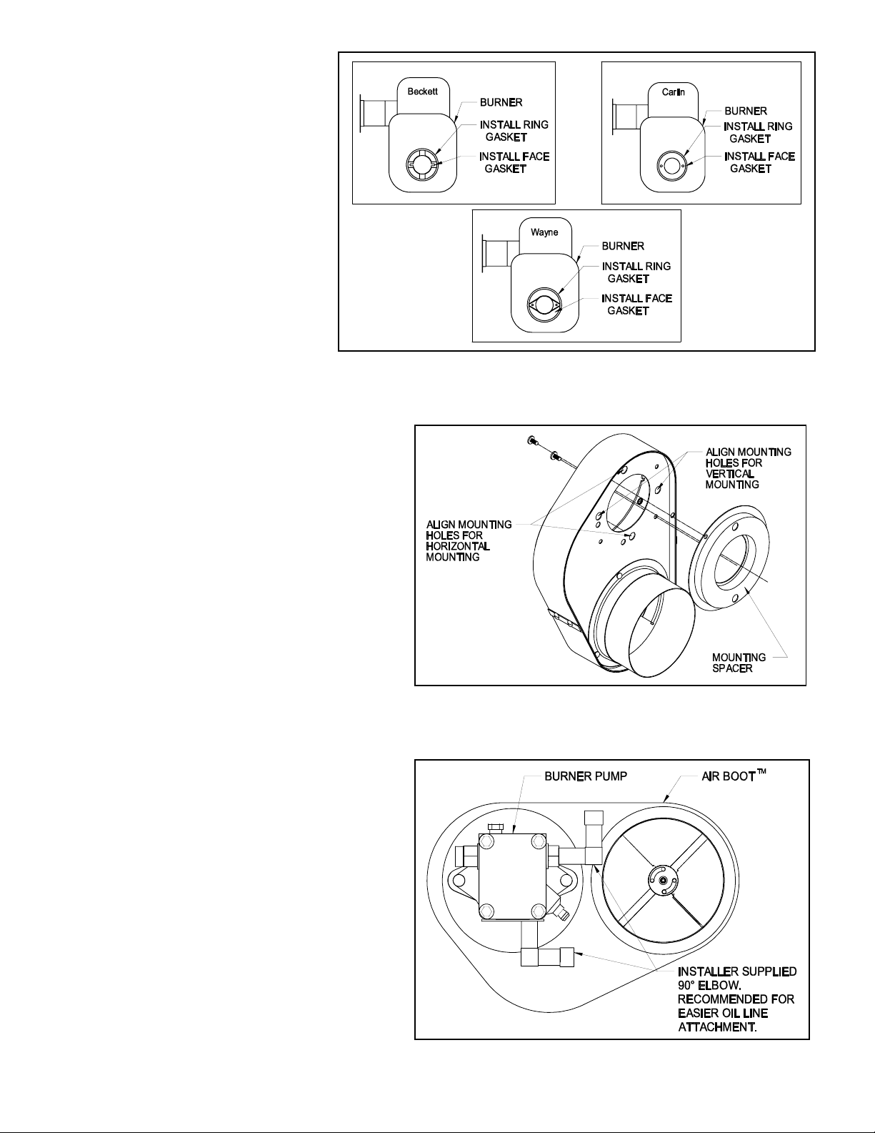
1. Remove the oil pump and air
bands from the burner housing.
Install the sealing gaskets
onto the burner housing.
Failure to install the ring
gasket onto the burner
housing will result in unlevel
boot, noisy operation, and
improper CO
2
readings. (See
Figure 1) Install mounting
spacer onto Air Boot™. (See
Figure 2) Position the Air
Boot™ over the burner
housing on the intake. The Air
Boot™ can be mounted onto
the burner in a horizontal or
vertical position. Install
mounting spacer onto Air
Boot™. Align the holes in the
Figure 1
Figure 2
Figure 3

Page 3
Air Boot™ with the holes in the
housing and re-attach the oil pump.
(See Figure 3) Important: Replace
pump coupling with the coupling
supplied with kit or pump operation
problems may occur. Note that the
Air Boot™ may be oriented either
vertically or horizontally as space
allows. The round spacer plate
attached to the Air Boot™ must be
removed and rotated 90° if vertical
mounting is needed.
2. FOR LOW FIRING RATE
APPLICATIONS WITH BURNER
INPUTS UP TO .75 GPH (CAS-2B
ONLY)
a. Insert flow restrictor pan in the
inlet collar with the flat of the
pan inward. (See Figure 4)
b. Push the pan in all the way,
approximately 5/8” from the air
adjustment blades. (See Figure
5)
Mount VRV tee assembly or
90° elbow onto the Air Boot™
intake. Fasten using three (3)
sheet metal screws spaced
120° apart on all joints. (See
Figure 6)
3. Assemble VRV balance weight
onto the gate. Screw the weight all
the way in. Then attach lock nut
and knurl nut. (See Figure 7)
4. Mount the VRV assembly onto the
tee and fasten with a screw and
nut in collar tabs. To ensure
proper operation, check the gate
for being level across the pivot
points and plumb. (See Figure 8)
5. Refer to Figure 9 for general
installation layout.
T
ERMINATION LOCATION GUIDELINES
1. Mount intake hood 12 inches above
finished grade. If mounting on the
side of a building prone to drifting
snow, mount 12 inches above the
snow line.
2. Mount at least 12 inches from either
side of the vent termination and on
the same wall if sidewall venting.
3. Always mount with the inlet vent termination opening pointing down.
NOTE: Make sure hood is kept free of debris.
Figure 6
Figure 5
Figure 4
 Loading...