


SYSTEM CONTROL KIT
Model: CK-43F
Designed for use with the SWG Series Power Venter for controlling Natural Gas or L.P. Gas draft induced appliances.
ITEMS INCLUDED IN KIT
1)Junction box with mounted pressure switch and post purge timer
1)2 ft. length of 1/4 inch aluminum tubing
2)Flexible conduit connector
1) 4" MG1 Barometric Draft Control
1) 1/4 inch tubing connector
DO NOT DESTROY
THESE INSTRUCTIONS MUST REMAIN WITH EQUIPMENT

INSTALLATION
Typical Vent System Layout
MOUNTING JUNCTION BOX
The junction box can be mounted at the venter or remotely mounted away from the venter. (See Figure 1 & Figure 2)
1.Remove one of the knockouts from the side of the junction box where the pressure switch is mounted. Install the flexible conduit connector onto the CK-43F junction box and secure with fastening nut. If remote mounting the CK-43F junction box, mount the flexible conduit connector onto a 2" x 4" installer supplied junction box.
2.Fasten the flexible conduit from the SWG Venter into the conduit connector. Mount the CK-43F junction box or installer supplied junction box onto the wall or floor joist without straining the flexible conduit. Fasten the CK-43F junction box through the four dimpled locations on the base of the box. (See Figure 3)
PRESSURE SWITCH SENSING TUBE INSTALLATION
1.Attach the 1/4 inch tubing connector to the pressure tube on the SWG Venter. (See Figure 3)
2.Connect the supplied 1/4" aluminum tubing to the tubing connector. Route the tubing to the CK-43F junction box and connect the tubing to the pressure switch. When routing the tubing, avoid kinking the tubing by bending the tubing too sharply.
For remote mounted CK-43F Junction Box, use a 1/4" OD copper, aluminum or plastic tubing and route the tubing to avoid contact with any heat source.
Figure 1
Figure 2
Page 2
Figure 3
DRAFT CONTROL INSTALLATION
CAUTION: This draft control is shipped as a single acting draft control. If the draft control is not being used on a gas draft induced furnace, remove the gate stop on the draft control ring before installing.
COLLAR INSTALLATION
This control is shipped with a collar patterned to fit a single wall round vent pipe. To attach this collar to the flue, see Figure 4 and follow the instructions below.
1. |
Bend outward the two ears at the front corners of the collar. Bend 90 degrees, |
|
|
|
1/4 inch behind the single hole on the straps. |
Figure 4 |
|
2. |
Insert clamping screw in ears on collar and bolt the remainder of the collar |
||
|
together.
3.Hold the collar against the side of the flue in the exact position it is to be installed (shown by dotted lines) and mark the outline of the collar on the flue.
4.Cut a hole in the flue about 1/2" inside of this outline.
5.Make a series of cuts about 1/2" apart from the edge of this hole to the outline marks.
6.Strap the collar to the flue pipe.
7.Bend the tabs formed by the series of cuts outward against the inside of the collar to make a tight joint.
8.Insert the draft control. (See Draft Control Installation and Adjustment Section.)
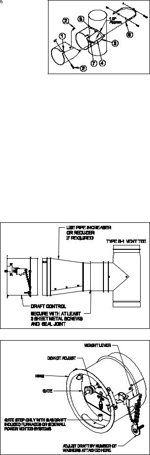
DRAFT CONTROL INSTALLATION IN TYPE B VENT PIPE
CAUTION: DO NOT use the supplied collar when mounting draft control to Type B Vent Pipe. Install by using a Type B Vent Pipe Tee.
1.Install a vent pipe reducer or increaser into the inner pipe and fasten using sheet metal screws. (See Figure 5)
2.The opening of the Type B Vent Tee, at the draft control mounting location, should be sealed with a high temperature sealant or equivalent.
3.Refer to Draft Control Installation Section.
DRAFT CONTROL INSTALLATION
Insert the draft control into the collar or tee. The front face of the control MUST be plumb and the bearing surfaces MUST be level whether the control is on a horizontal, vertical or sloping flue pipe.
Use a spirit level and level accurately. (See Figure 5) Secure the control in the collar by tightening the clamping screws. If a tee is used or a collar is supplied locally, the control may be held in place by sheet metal screws.
ADJUSTING THE DRAFT CONTROL WITH 4" MG1
The control MUST be adjusted to the desired draft setting by adding or removing the washer-type weights supported by the two chains on the side of the draft control. (See Figure 6) DO NOT move the weight attached directly to the gate, this is used only for balancing at the factory.
Figure 5
Figure 6
Page 3
 Loading...