


120 VAC SYSTEM CONTROL KIT
Model: CK-61
Designed for use on SWG Series Power Vent Hoods for controlling oil fired heating appliances with 120 VAC controls.
ITEMS INCLUDED IN KIT:
1) Junction box with mounted pressure switch and solid state post purge control 1) 2 Ft. Length of 1/4 inch aluminum tubing
1) 1/4 inch tubing connector
1) Flexible conduit connector
1) WMO-1 Secondary Safety Switch
DO NOT DESTROY
THESE INSTRUCTIONS MUST REMAIN WITH EQUIPMENT
INSTALLATION
MOUNTING JUNCTION BOX
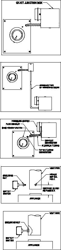
The junction box can be mounted at the venter or remotely mounted away from the venter. (See Figure 1 & Figure 2)
1.Remove one of the knockouts from the side of the junction box where the pressure switch is mounted. Install the flexible conduit connector onto the CK-61 Junction Box and secure with fastening nut. If remote mounting the CK-61 Junction Box, mount the flexible conduit connector onto a 2" x 4" installer supplied junction box.
2.Fasten the flexible conduit from the SWG Venter into the conduit connector. Mount the CK-61 Junction box or installer supplied junction box onto the wall or floor joist without straining the flexible conduit. Fasten the CK61 Junction Box through the four dimpled locations on the base of the box. (See Figure 3)
OIL FIRED SECONDARY SAFETY SWITCH (WMO-1)
Installation of a SECONDARY SAFETY SWITCH (WMO-1) is recommended for detecting flue gas spillage from a blocked flue system and/or inadequate draft.
1.Pierce a 5/8" dia. hole into the vent pipe near the appliance outlet. Remove one of the securing nuts from the shaft of the safety switch. (See Figure 4) Tighten the other securing nut onto the pipe as far as possible.
2.Insert the threaded pipe end into the pierced hole, then install the securing nut, which was removed in Step 1, and tighten securely (See Figure 5)
3.Wire safety switch in series into one side of the burner circuit. Refer to Unit Wiring Instructions.
CAUTION: If for any reason the system has shut down during operation, the cause of the system failure should be investigated and corrected before resetting the safety switch and restarting the system.
PRESSURE SWITCH SENSING TUBE INSTALLATION
1.Attach the 1/4 inch tubing connector to the pressure tube on the SWG Venter. (See Figure 3)
2.Connect the supplied 1/4" aluminum tubing to the tubing connector. Route the tubing to the CK61 Junction Box and connect the tubing to the pressure switch. When routing the tubing avoid kinking the tubing by bending the tubing too sharply.
3.For remote mounted CK-61 Junction Box, use a 1/4" OD copper, aluminum or plastic tubing and route the tubing to avoid contact with any heat source.
Refer to the SWG Venter installation instructions for setting system airflow.
Page 2
Figure 1
Figure 2
Figure 3
Figure 4
Figure 5

WIRING INSTRUCTIONS
Wire the venter motor and controls in accordance with the National Electrical Code, manufacturer's recommendations and/or applicable local codes. UNIT MUST BE GROUNDED. Check ground circuit to make certain that the unit has been properly grounded. The wiring should be protected by an over current circuit device rated at 15 amperes. Caution must be taken to ensure that the wiring does not come into contact with any heat source. All line voltage and safety control circuits, between the venter and the appliance, MUST be wired in accordance with the
National Electrical Code for
Diagram A – Oil Fired System: Single Unit Wiring
Class I wiring or equivalent methods. Route the venter motor and control wiring with an appropriate wiring method. (Diagrams A through E)
Diagram B – Oil Fired System: Wiring with Electronic Primary
Page 3
 Loading...