

Page 1

User’s Guide
www.fetco.com
CBS-3000P Series Coffee Brewers
Contact Information ................................................ 2
Product Description/Features ................................. 2
Technical Data........................................................ 2
Dimensional Drawings & Utilities............................3
Installation............................................................... 4
Pour-Over Models:
f CBS-31P
f CBS-31Pap
Table of Contents
Brewing Specifications........................................ 2
Weights and Capacities ...................................... 2
Electrical Configuration and Brewing Efficiency .2
Operating Procedures ............................................ 5
Service.................................................................... 6
Warranty.............................................................. 6
Adjustments ........................................................ 6
Troubleshooting .................................................. 7
Parts ....................................................................... 8
FETCO® and Driven To Pioneer Innovation™ are trademarks or trade names of Food Equipment Technologies Company.
© 2006 Food Equipment Technologies Company Part # P003 August 2, 2006
Page 2
Contact Information
FETCO®
Food Equipment Technologies Company
600 Rose Road
Lake Zurich • IL • 60047-0429 • USA
Internet: www.fetco.com
Phone: (800) 338-2699 (US & Canada)
(847) 719-3000
Fax: (847) 719-3001
Email: sales@fetco.com
techsupport@fetco.com
Product Description/Features
CBS-31P Coffee Brewing System
CBS-31Pap Coffee Brewing System
• Pour-over, requires no plumbing
• Compact design • Iced tea brewing capability
• All stainless steel brewer body construction • Color stainless steel finish
• Electronic temperature control • Custom and export voltage
• “Ready to brew” indicator lamp
• Non clog sprayhead
• Heater protection control
Note: Throughout this manual, all references to the CBS-31 brewer apply to both the “P” and “Pap” versions, unless
otherwise indicated.
Used with 2.5 liter thermal gravity pots
Used with various size airpots*
Optional Features:
Technical Data
Brewing Specifications
CBS-31P CBS-31Pap
Brew Volume: 2.5 liters 2.2 liters / 3.0 liters Temperature:
Brew Time: 3½ - 4 min 3-3½ min. / 4-4½ min.
(Allow an extra 1-3 minutes for coffee to finish dripping)
Coffee Filters: Plastic Brew Basket: 9¾” X 4½” FETCO # F003
Stainless Steel Brew Basket: 13” X 5” FETCO # F002
*FETCO currently supplies 2.2 and 3.0 liter airpots. Pap brewers can also utilize the other available sizes, 1.9 and 2.5 liters.
Weights and Capacities
Brewer
Model
CBS-31P/Pap 30 lbs. 1.7 gal. 14.2 lbs. 44.2 lbs. 4 lbs. 10.3 lbs. 55 lbs.
Weight
(empty)
Water tank
Capacity & Weight
Weight
(filled)
Dispenser
Weight, ea.
Electrical Configuration and Brewing Efficiency
Brews per Hour (cold or hot water)
Heater Voltage Max. Amp 2.2 lit. (max 13) 2.5 lit. (max 12) 3.0 lit.(max 11)
Model Configuration Connection Phase Wires KW draw cold hot cold hot cold hot
CBS-31P/Pap (-1) 1 X 1300 w 120 1 ph. 2 + grnd 1.3 11.2 5.5 12.8 4.9 11.3 4.1 9.4
CBS-31P/Pap (-2) 1 X 1800 w 120 1 ph. 2 + grnd 1.8 15.3 7.7 13.0 6.8 12.0 5.6 11.0
203°F inside water tank (at sea level)
195°F ± 5° at sprayhead
Dispenser.
Filled, ea.
Total Weight Brewer&
Dispensers, filled
2
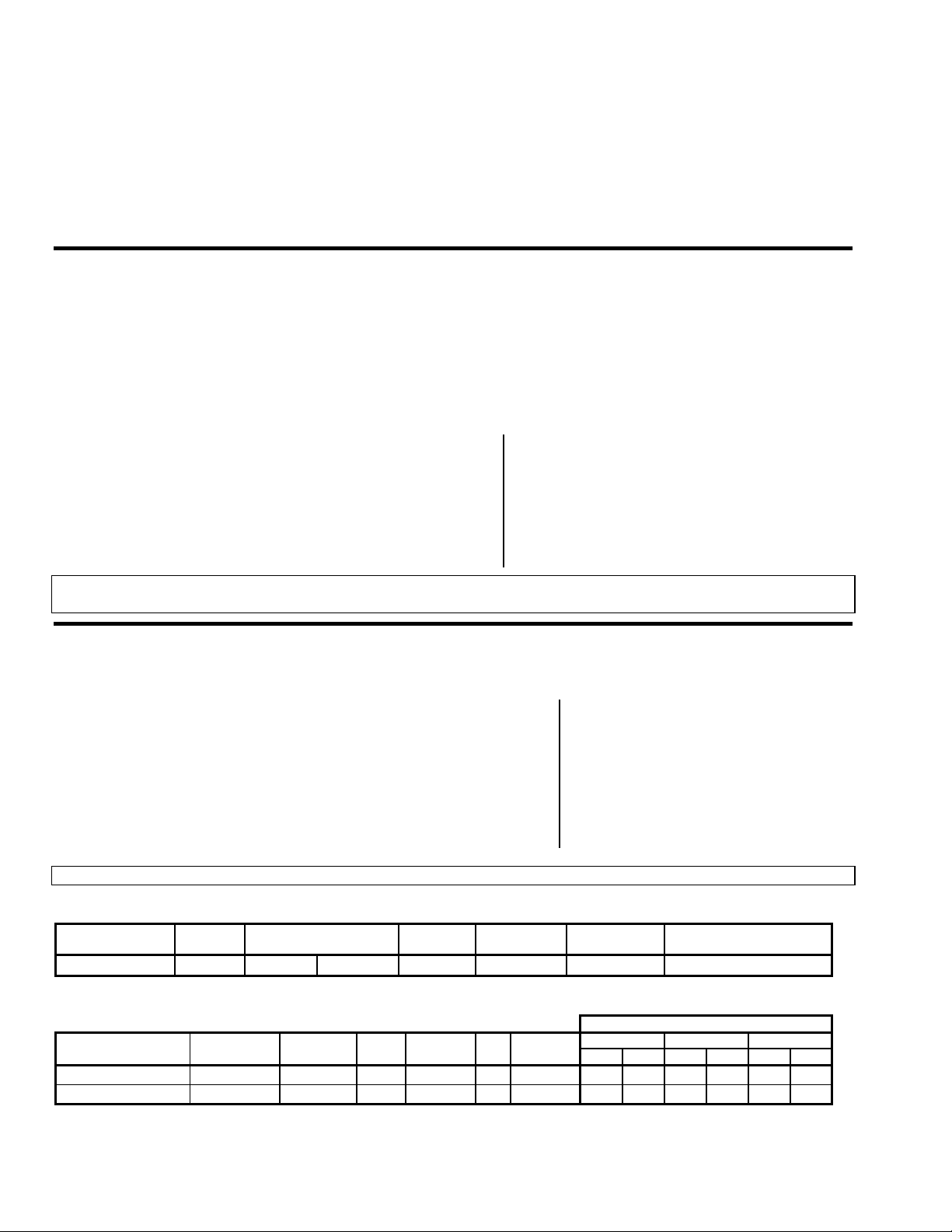
Page 3
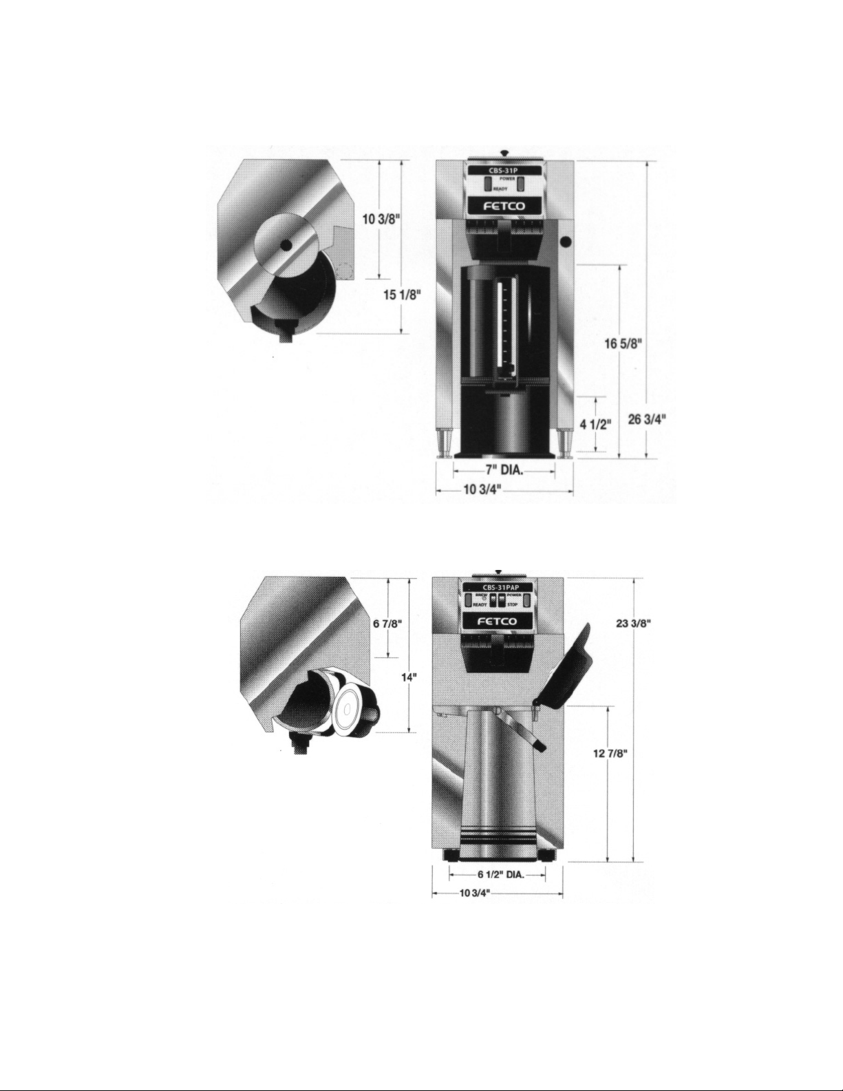
CBS-31P
Dimensional Drawings & Utilities
CBS-31Pap
3
Page 4

Installation
(For Qualified Service Technicians Only)
Keys Points
Electrical:
•The electronic controls require at least 105 volts. Less than 105 volts will cause erratic behavior from the
brewer.
•The electrical drawing for the brewer is located on the inside of the upper cover.
General:
•Do not adjust the thermostat setting unless absolutely necessary. It is set at the factory for optimum
performance.
Installation Instructions
1. Review the Dimensional Drawings and the Operating Procedures for the unit you are installing. Verify that
the brewer will fit in the space intended for it. Verify that the counter or table will support 55 lbs., the weight
of the brewer and dispensers when filled.
2. The thermostat is pre-set at the factory. There is no need to turn off the heater during the installation
process. The heater is disabled by the liquid level control board until water is sensed. The heating
process will start automatically when the tank has filled with water.
3. When the brewer is in position for use, level the brewer front to back as well as side to side by adjusting the
feet.
4. Plug the power cord into a proper receptacle
5. Turn the power switch to the “on” position.
• The “ready” light will go on briefly, then go off.
• The heaters will be disabled by the L.L.C. board until water is sensed by the water level probe.
6. Fill the water tank as follows:
• Remove the pour-over tank cover.
• Place a container under the brew basket.
• Slowly pour approximately 1½ gallons of water into the top of the brewer. This will almost completely
fill the brewer’s main tank.
• Pour additional water into the top until water begins flowing out of the brew basket into the container.
• The brewer’s tank is now completely full and the water will begin heating.
• Due to the expansion of the water as the temperature rises, water will drip from the brew basket during
the heating process. Therefore, the brew basket and container should be kept in place until the water
has reached operating temperature.
The brewer will be ready for operation as soon as the ready light comes on to indicate that the water tank is
up to brewing temperature. The time required to reach brewing temperature will vary according to the electrical
configuration and the temperature of the cold water.
Depending on the cost of electricity in your area, very little savings may be had by turning the brewer off
between shifts. The water tank is well insulated and may actually use less electricity to keep the tank hot, than reheating the tank from a cold condition. Leaving the brewer in the on position will also avoid delays at the beginning
of shifts for the brewer to reach operating temperature.
7. Review the entire operating procedures with whomever will be using the brewer. Pay particular attention to
the following areas.
• Don't remove the brew basket until it has stopped dripping.
• Make sure the dispenser is empty before brewing into it.
• Show how to close and/or secure the dispensers for transporting.
4
Page 5

Operating Procedures
1. Turn the power switch
• The power switch will illuminate to indicate that the brewer has power.
• When the ready light
time required to gain full operating temperature will vary depending on the electrical configuration that
was ordered, and the temperature of the cold water.
2. Prepare the brew basket
• Place a paper filter in each basket to be used. Pour the appropriate amount of pre-measured, ground
coffee into the filter. The amount of coffee used will depend on your personal tastes and the
recommendation of your roaster.
• Slide the brew basket back into the rails on the brewer.
3. Prepare the dispenser.
• Ensure that the dispenser is empty. If you are using an
airpot, open the cover and remove the pump stem
before brewing.
• Place the dispenser in position under the brew basket.
4. Remove the tank cover
amount of water into the top of the brewer.
• It is normal for the ready light to go out after the start of
the brew cycle.
• The electrical configuration and the electrical power
connected to the brewer will determine how long before
the ready light comes back on for the next brew.
5. You now have a dispenser of freshly brewed coffee, ready to serve, that will taste fresh and stay hot.
ONLY a non-heated dispenser can do that.
• If you are using an airpot, insert the pump stem before closing the cover.
CAUTION:
Do not remove the brew basket immediately after the brew cycle has finished. Wait until
dripping from the bottom of the brew basket has stopped. Carefully remove the brew basket
while inspecting the inside of the basket for hot coffee that has not finished draining.
(A) to the on position
(B) illuminates, the brewer is fully up to brewing temperature. The amount of
(C).
(D), and pour the appropriate
Gravity pot
Airpot
D
Legend:
Power switch
A-
Ready light
BC-Brew basket
D-Pour-over tank cover
B
POWER
READY
A
C
5
Page 6

Service
Warranty
All FETCO brewers come with a limited warranty. All warranty service must be authorized by calling FETCO
Technical Support at (800) 338-2699.
Adjustments
Thermostat Adjustment:
For equipment manufactured before April 1, 2004
The brewer’s water tank temperature is factory set at 205°F (slightly lower for high altitudes, to prevent boiling).
This setting will deliver water at 195°F ± 5° to the coffee grounds.
Measure the temperature by holding a thermometer in the stream of water flowing out of the brew basket, 1/3 of
the way through the brew cycle. The temperature should be 195°F ± 5°.
If an adjustment is necessary:
• Turn the power switch off.
• Remove the four screws on the upper cover. The upper water tank is attached to the cover.
• Lift the cover and tank just enough to reach the thermostat, which
is located on the right side, under the tank.
• Turn the adjustment stem slightly counter-clockwise to increase
the temperature, and clockwise to decrease the temperature.
• Place the tank and cover in their normal positions and turn the
power switch on.
• If you decreased the temperature setting, place a container
under the brew basket and pour water into the top of the brewer
until the “ready” light goes out
• Wait for the “ready” light to come on, and measure the temperature again.
Repeat until the desired temperature is obtained.
Effective December, 2004:
A new digital thermostat and temperature probe were introduced as a direct replacement for the old style
thermostat and probe.
During normal operation, the digital readout displays the last two digits of the actual water temperature. When the
adjustment tool is turned, the readout begins flashing to indicate the set point, not the actual temperature. After the
tool is released, the readout stops flashing and displays the actual temperature again.
A red LED lights when the power to the thermostat is on. A yellow LED lights when the thermostat is calling for
heat.
To adjust, turn the adjustment tool. If no adjustment tool is present, a small flat-head screwdriver may be used. The
display will flash, indicating that the display is showing the set point, not the actual temperature.
The dots below the numbers indicate the temp range.
0 dots – less than 100° F
1 dot – between 100° and 200° F
2 dots – over 200° F
Thermostat
Examples:
7 5
8 7
= 75°F
= 187°F
0 3
= 203°F
6
Page 7

Troubleshooting
Brewing Problem Possible Cause Solution
Short brew levels
High brew levels
Dispenser not empty -Empty the dispenser completely and try again
Brew basket or filter overflows
Grounds not saturated
Water Softener in use -Obtain water from a non-softened source.
Weak Coffee
Too many filter papers -Make sure only one paper is used
Low brew temperature
Spray head / brew basket drips
Coffee tastes too strong
Short brew levels -See “Short brew levels”, above.
Incorrect amount of water poured
in top of brewer.
Incorrect amount of water poured
into top of brewer.
-Call FETCO Service Dept. to discuss. (800) 338-2699
Half batch used incorrectly -Use smaller brew basket
Degassing - extremely fresh
coffee
Improper dose -Measure and confirm correct dose
(Temperature inside the water
tank should be set to 203° F.)
Condensation around the
sprayhead area
Condensation from water tank
dripping through dispense tube
Incorrect dosage -Measure and confirm the correct amount of coffee
Temperature Problem (brewer only) Possible Cause Solution
Brew water is cold / not hot enough,
ready light is OFF.
Water tank is not full.
Defective liquid level control
Bad heating element.
Brew water is cold / not hot enough,
ready light is ON.
Slow to recover temperature
(Ready light takes a long time to come
back on after brewing.)
Boiling and Steams
No power to brewer. -Make sure power switch is on
(If the brewer has not been used
for an extended period, the
water level may drop below the
probe tip, disabling the
thermostat.)
board.
(No power to thermostat).
Bad Thermostat
(The thermostat believes that it is
at set temperature)
Low brew temperature
(Temperature inside the water
tank should be set to 203° F.)
Hot water tank limed up -Remove access cover to the hot water tank and inspect
Thermostat set too high for
altitude (Denver etc.)
Defective thermostat -Replace the thermostat and or thermal probe. It’s not
Dispenser Problem Possible Cause Solution
Coffee not hot enough
Using 1/2 batch on regular basis -Encourage full batch use except at end of day or shift.
Parts related problems
Attempting to hold coffee too
long.
-Contact dispenser manufacturer:
Use correct amount of water for the size of the dispenser
being used.
Use correct amount of water for the size of the dispenser
being used.
-Call FETCO Service Dept. to discuss.
(800) 338-2699
-Adjust thermostat so the water stream measured at the
bottom of the brew basket, 1/3 of the way through the
brew cycle, equals 195 degrees + or - 5 degrees
-Wipe sprayhead area after brewing; place an empty
container under brew cone when not in use.
-Insert an empty brew basket and server under brew
heads when not in use
required
-Make sure brewer is plugged in.
-Check the wall circuit breaker / reset
-Refill the tank by pouring water into the top of the
brewer until it begins flowing out of the sprayhead.
-With power on, and water tank full, disconnect the
green wire connected to the water level probe.
Touching this wire to the tank should cause the relay
on the control board to click. If not, replace the board.
-Check amperage draw on heater wires. 0 amps = bad
heater.
-Replace the thermostat and or thermal probe. It’s not
possible to trouble shoot the probe.
-Adjust thermostat so the water stream measured at the
bottom of the brew basket, 1/3 of the way through the
brew cycle, equals 195 degrees + or - 5 degrees
for lime. Remove the brewer for shop de-liming if build
up is thick.
-Reduce temperature setting to 3 degrees below boiling
at your altitude
possible to trouble shoot the probe.
-Review discard times
Explore the need for smaller dispensers
Zojirushi - (800) 733-6270
Techni-Brew - (800) 545-4077
7
Page 8

CBS-31P
Parts
ITEM QTY PART NO. DESCRIPTION
1 1 72006 KNOB, WATER INLET COVER
2 1 01180 WATER INLET LID
3 1 82041 CHAIN, #10, ROUND BEAD
4 1 01160 COVER TOP
5a 1 23174 LID, UPPER TANK
5b 1 23200 BODY, UPPER TANK
6 1
6 1
7 1 31036 FITTING, COMPR., MALE CONNECT.,1/4 TUBE OD. X 1/4 MPT
8 1 83064 WASHER, .812" OD X .563"ID, FLAT
10 2 31117 LOCKNUT, 1/4 STRAIGHT PIPE THREAD
11 1 12030 WATER LEVEL PROBE FITTING
12 1 21069 BREW HOUSING
53015 thermostat temp probe 14" (use with K045 digital thermostat or 53012 thermostat)
102198 Digital temp probe assy., 14” (use with K045 digital thermostat only)
8
Page 9

13 1 31101 FITTING, BARB, 90 ELBOW, 1/2 HOSE ID X 3/8 MPT
14 2 31118 LOCKNUT, 3/8 STRAIGHT PIPE THREAD
15 1 21038 HOUSING, ELECTRODE
16 1 002034 WELDMENT, WATER LEVEL PROBE
17 1 102047 TANK COVER ASSY
18 1 25094 VENT,SILICONE TUBE,
19 1 32047 TUBE, FITTING, TANK
20 1 32045 TUBE, FITTING, BREW
21 1 25095 TUBE, SILICONE
22 1 03098 BRACKET, SPRAY HEAD HOLDING
23 1 83065 WASHER, 1.0"OD X .412"ID, FLAT
24 1 24036 O'RING, .562" OD X .375" ID
25 1 21061 FLOW DISC, DISENSE
26 1 23104 SPRAY CUTTER, CLEAR, 6 + 1 HOLE
27 1 24010 O'RING SPRAY CUTTER
35 1 52023 TERMINAL BLOCK
36 2 82054 #6-32 X .625 S.S., PHIL, MS.
37 1 01152 BACK COVER
38 1 401044 WIRING DIAGRAM
39 1 22048 INSULATION
40 1 03076 BRACKET, THERMOSTAT
41 1 K045 DIGITAL THERMOSTAT, 100-120VAC
41 1 K046 DIGITAL THERMOSTAT, 200-240VAC (EXPORT ONLY)
42 1 108055 Liquid Level Control Brd. 100-120VAC, digital
42 1 108056 Liquid Level Control Brd. 200-240VAC, digital (EXPORT ONLY)
43 1 107006 1300W, 120VAC HEATER KIT
43 1 107007 1800W, 120VAC HEATER KIT
43 1 107001 2300W, 240VAC HEATER KIT (EXPORT ONLY)
44 1 004008 TANK WELDMENT
45 1 31116 1/8 LOCKNUT SPT
46 1 83041 .812 X .412 FLAT WASHER
47 1 31076 FITTING BARB, 1/8 MPT X 5/16
48 1 25024 TUBE, SILICONE, DRAIN
49 1 102032 CORD, 120VAC, 15AMPS W/5-15P NEMA PLUG ASSY.
49 1 102033 CORD, 120VAC, 20AMP W/5-20P NEMA PLUG ASSY
49 1 102035 CORD, 16AMP W/EUROPEAN PLUG ASSY
49 1 102050 CORD 15AMP W/AUSTRALIAN PLUG ASSY
49 1 102049 CORD, 15AMP W/BRITISH PLUG ASSY
50 1 86012 BUSHING, HEYCO STRAIN RELIEF
51 1 31086 VALVE, DRAIN
52 1 31087 FITTING, DRAIN VALVE CONNECT
53 1 58064 LAMP "READY" INDICATOR GREEN, 120VAC
54 1 58063 SWITCH, POWER ROCKET, RED, 240VAC
55 1 46009 LABEL, INFO. SET CBS-30'S
56 6 84002 NUT, HEX #8-32 S.S., MS
57 2 82049 SCREW, ROUND HD, PHIL, MS.#6-32 X 1/4
58 1 25011 TUBE,SILICONE,
60 1 23036 BREW BASKET,BROWN PLASTIC (9-3/4 X 4-1/2 FILTER)
60 1 23035 BREW BASKET, BLACK PLASTIC (9-3/4 X 4-1/2 FILTER) TEA
61 1 86038 CLAMP, HEYCO HOSE
62 1 25004 TUBE, 1/4OD X 1/8ID TEMP.PROBE COVER
63 1 84006 NUT, CAP, #8-32
67 5 83026 WASHER, #8 INTER. TOOTH LOCK
69 3 84001 NUT, #6-32, MS, S.S.
70 2 84002 NUT HEX, #8-32 S.S. MS.
71 3 83011 WASHER, #6, INTERN. TOOTH LOCK
72 10 82053 SCREW,S.S. #6-32 X 1/2, TRUSS HD,PHIL MS
73 4 73007 LEG, 2.5" HIGH, ADJUSTABLE
74 1 83063 WASHER,FLAT, .536 X .875 X .060TH
75 1 24002 TANK COVER GASKET
76 1 09010 BASKET, WIRE, 13 X 5, GOURMET
77 1 101098 ASSY, BREW BASKET, 13 X 5 (OPTIONAL)
78 1 102072 HANDLE ASSY WITH SCREWS & INSERTS
79 2 82042 FITTING, BEAD CHAIN
80 1 102046 WATER POUR OVER LID COVER ASSY
81 4 73002 LEG, 4.0" ADJUSTABLE, FLANGED FOOT
9
Page 10

CBS-31Pap
ITEM QTY PART NO. DESCRIPTION
1 1 72006 KNOB, WATER INLET COVER
2 1 01180 WATER INLET LID
4 1 01160 COVER TOP
5 1 23047 UPPER TANK
6 1
6 1
7 1 31036 FITTING, COMPR., MALE CONNECT.,1/4 TUBE OD. X 1/4 MPT
8 1 83064 WASHER, .812" OD X .563"ID, FLAT
10 2 31117 LOCKNUT, 1/4 STRAIGHT PIPE THREAD
11 1 12030 WATER LEVEL PROBE FITTING
12 1 21069 BREW HOUSING
13 1 31101 FITTING, BARB, 90 ELBOW, 1/2 HOSE ID X 3/8 MPT
14 2 31118 LOCKNUT, 3/8 STRAIGHT PIPE THREAD
15 1 21038 HOUSING, ELECTRODE
16 1 002034 WELDMENT, WATER LEVEL PROBE
17 1 102047 TANK COVER ASSY
53015 thermostat temp probe 14" (use with K045 digital thermostat or 53012 thermostat)
102198 Digital temp probe assy., 14” (use with K045 digital thermostat only)
10
Page 11

18 1 25094 VENT, SILICONE, TUBE
19 1 32047 TUBE, FITTING, TANK
20 1 32045 TUBE, FITTING, BREW
21 1 25095 TUBE, SILICONE
22 1 03098 BRACKET, SPRAY HEAD HOLDING
23 1 83065 WASHER, 1.0"OD X .412"ID, FLAT
24 1 24036 O'RING, .562" OD X .375" ID
25 1 21061 FLOW DISC, DISPENSE
26 1 23104 SPRAY CUTTER, CLEAR, 6 + 1 HOLE
27 1 24010 O'RING SPRAY CUTTER
29 2 01490 LEG CHANNEL
30 4 83027 WASHER, 1/4" SCREW SIZE, INTERNAL TOOTH LOCK
31 4 82073 SCREW, SOCKED HD, CAP, 1/4-20 X 1/2LG
32 4 73016 LEG, 1.0" HIGH
34 1 83041 WASHER, .812"OD X .412"ID FLAT
35 1 52023 TERMINAL BLOCK
36 2 82054 #6-32 X .625 S.S, PHIL, MS.
37 1 01152 BACK COVER
38 1 401044 WIRING DIAGRAM
39 1 22048 INSULATION
40 1 03076 THERMOSTAT BRACKET
41 1 K045 DIGITAL THERMOSTAT, 100-120VAC
41 1 K046 DIGITAL THERMOSTAT, 200-240VAC (EXPORT ONLY)
42 1 108055 Liquid Level Control Brd. 100-120VAC, digital
42 1 108056 Liquid Level Control Brd. 200-240VAC, digital (EXPORT ONLY)
43 1 107006 1300W, 120VAC HEATER KIT
43 1 107001 2300W,240VAC HEATER KIT (EXPORT ONLY)
43 1 107007 1800W 120VAC HEATER KIT
44 1 004008 TANK WELDMENT
45 1 31116 1/8 LOCKNUT SPT
47 1 31076 FITTING, BARB, 1/8 MPT X 5/16
48 1 25024 TUBE SILICONE, DRAIN
49 1 102033 CORD, 120VAC, 20AMP W/5-20P NEMA PLUG ASSY
49 1 102035 CORD, 16AMP W/EUROPEAN PLUG ASSY
49 1 102050 CORD 15AMP W/AUSTRALIAN PLUG ASSY
49 1 102049 CORD, 15AMP W/BRITISH PLUG ASSY
49 1 102032 CORD, 120VAC, 15AMPS W/5-15P NEMA PLUG ASSY.
50 1 86012 BUSHING, HEYCO STRAIN RELIEF
51 1 31086 VALVE,DRAIN
52 1 31087 FITTING, DRAIN VALVE CONNECT
53 1 58064 LAMP "READY" INDICATOR GREEN, 120VAC
54 1 58063 SWITCH, POWER ROCKET, RED 240VAC
55 1 46009 LABEL, INFO. SET CBS-30'S
56 6 84002 NUT, HEX, #8-32 S.S, MS
57 2 82049 SCREW,ROUND HD, PHIL, MS. #6-32 X 1/4
58 1 25011 TUBE, SILICONE
60 1 23035 BREW BASKET,BLACK, PLASTIC (9-3/4 X 4-1/2 FILTER) TEA
60 1 23036 BREW BASKET, BROWN, PLASTIC (9-3/4 X 4-1/2 FILTER)
61 1 86038 CLAMP, HEYCO HOSE
62 1 25004 TUBE1/4 OD 1/8 ID TEMP. PROBE COVER
63 1 84006 NUT, CAP, #8-32
66 1 82041 CHAIN, #10 ROUND BEAD
67 1 82042 FITTING, BEAD CHAIN
68 7 83026 WASHER, #8 INTER. TOOTH
69 1 83063 WASHER,FLAT, .536 X .875 X .060TH
70 3 84001 NUT, #6-32, S.S.
71 3 83011 WASHER, #6, INTERN. TOOTH
72 10 82053 SCREW,S.S. #6-32 X 1/2, TRUSS HD, PHIL, MS.
73 1 09010 BASKET, WIRE, 13 X 5, GOURMET
74 1 101098 ASSY, BREW BASKET, 13 X 5 (OPTION)
75 1 102072 HANDLE ASSY WITH SCREWS & INSERTS
76 1 102046 WATER POUR OVER INLET LID ASSY
77 1 24002 COVER GASKET
11
Page 12

 Loading...