

Page 1

®
Model
www.fetco.com
Contact Information ........................................................2
Description & Features ...................................................2
Specifications..................................................................2
Requirements .................................................................2
Weights Capacities and Measurements.........................3
Electrical Configuration and Brewing Efficiency .............3
Installation.......................................................................5
Accessing batch and programming menu screens ........8
NOTICE TO INSTALLER: Please leave this book with the machine.
Table of Contents
User’s Guide
s:
f CBS-2131
f CBS-2132
3 liter and 1 gallon airpot brewers
Operating Instructions...................................................10
Programming- operator access programming..............12
Hot water convenience tap ...........................................17
Adjustable spray pattern ...............................................17
Error Codes...................................................................17
Airpot use instructions and cleaning.............................18
Parts diagrams, bill of materials lists ............................22
Wiring diagrams............................................................33
FETCO®, LUXUS®, EXTRACTOR®, INTERMITTENT BREW, and Driven To Innovation™
are trademarks or trade names of Food Equipment Technologies Company.
© 2012 Food Equipment Technologies Company P114 Version1 October 2012
Page 2

Contact Information
FETCO
®
Food Equipment Technologies Company
600 Rose Road
Lake Zurich • IL • 60047-0429 • USA
Internet: www.fetco.com
Phone: (800) 338-2699 (US & Canada)
(847) 719-3000
Fax: (847) 719-3001
Email: sales@fetco.com
techsupport@fetco.com
Description & Features
The CBS-2130 Series coffee brewers feature our universal spray over technology, which works like this:
The following variables are programmed for each batch size:
Brew volume Prewet percent (Percentage of the brew volume)
Brew time Prewet delay (The time between prewetting and the brew cycle.)
Adjustable number of pulses Bypass percent (Percentage of the brew volume)
Three selectable spray patterns
Drip delay (The time between the end of the brew cycle to
empty the brewbasket and end of the brewing cycle.)
Using these variables, the software calculates how much water to use for prewetting, bypass (optional), and
brewing. The total brew time is divided into several cycles. Within these cycles, the software calculates how
long to spray water over the coffee grounds, and how long to pause before the next cycle begins. The optional
bypass valve opens at the beginning of the brew cycle and dispenses the correct amount of water all at once.
Spray pattern into brew basket may be user set for perfect penetration.
Features
Touchscreen Operation Pump circuit calibration on startup
Cascading Spray Dome-no holes to clog in sprayhead Magnetic flux brew basket sensor
Four fully programmable batch sizes per side Dispenser locator under brew basket
Batch sizing Brew at temperature protection
Customizable batch name Brew mechanism is digitally adjustable
Recipe copy Adjustable bypass (with bypass option)
Screen logo customizable by user from SD card Three adjustable spray patterns
SD card firmware program and upgrade installation Totalizing counters for brewer functions
User programs save to and load from SD cards Shipped ready to operate out of the box
Specifications
Requirements
Water Requirements: Inlet Water Temperature: Cold or Hot supply
CBS-2131: 20-75 psig (138-517kPa) 1½gpm/(5.7lpm)
CBS-2132: 20-75 psig (138-517kPa) 1½gpm/(5.7lpm) 13”X5”– standard FETCO # F002
Water inlet fitting is a 1/4 inch male flare. Electrical: See electrical configuration chart.
Brew Volume: Temperature:
Full Batch 3 liter CBS-2132 & CBS-2131—3 liter version
Full Batch 1gal. CBS-2132 & CBS-2131—1 gal. version
Designs, materials, specifications, physical dimensions, firmware and software protocol for equipment or replacement parts are subject to change by FETCO without notice.
2
Coffee Filter Size:
200°F (93°C) inside water tank (at sea level)
195°F (91°C) ± 5° at sprayhead
Page 3

Weights Capacities and Measurements
Weights and Capacities & Measurements; 3 liter and 1 gallon brewers
Brewer Height Width Depth
CBS-2131
3 liter
CBS-2131
I gallon
CBS-2132
3 liter
CBS-2132
I gallon
21 ⅜”
54.3cm
23 ⅜”
59.4cm
21 ⅜”
54.3cm
23 ⅜”
59.4cm
11 ¾”
30.3cm
11 ¾”
30.3cm
19 ¾”
50.2cm
19 ¾”
50.2cm
20 ⅜”
51.8cm
20 ⅜”
51.8cm
20 ⅜”
51.8cm
20 ⅜”
51.8cm
Empty
Weight
29 lb
13.1kg
29 lb
13.1kg
42.6lb
19.3 kg
42.6lb
19.3 kg
Filled
Weight
50 lb
22.7 kg
50 lb
22.7 kg
87.6 lb
39.7kg
87.6 lb
39.7 kg
Total Weight-
Brewer &
Filled Dispenser
61.2lb
27.8 kg
63lb
28.6 kg
110lb
49.9 kg
114 lb
51.7 kg
Shipping
Weight
36.3 lb
16.5 kg
36.3 lb
16.5 kg
49.4 lb
22.4 kg
49.4 lb
22.4 kg
Shipping Dimensions
22 ¾”x 16 5/8” x 22 7/8”
57.8 x42.3x58.1cm
22 ¾”x 16 5/8” x 22 7/8”
57.8 x42.3x58.1cm
24½” x 22⅞” x 23”
62.2 x 58.1 x 58.4cm
24½” x 22⅞” x 23”
62.2 x 58.1 x 58.4cm
Electrical Configuration and Brewing Efficiency
Electrical Configurations- CBS-2131—3 liter version
Configuration
Code
Heater
Configuration
Bypass
E213103 1 X 1.5 kW NO
E213104 1 X 1.7 kW NO
E213101 1 X 2.3 kW NO
E213105 1 X 2.3 kW NO
E213107 1 X 3.0 kW NO
Voltage
100 - 120
100 - 120
100 - 120
200 - 240
200 - 240
Phase
Wires
1 2+G NEMA 5-15P 1.1 –1.6 10.9 – 13.0 3.9 gal/14.8 lit
1 2+G NEMA 5-15P 1.3 – 1.8 12.3 - 14.7 4.4 gal/16.7 lit
1 2+G NEMA 5-20P 1.7 – 2.4 16.5 - 19.7 5.8 gal/22 lit
1 2+G Cord/No Plug 1.7 – 2.4 8.5 – 10.1 5.8 gal/22 lit
1 2+G Cord/No Plug 2.2 – 3.1 10.9 – 13.0 7.7 gal/29.1 lit
Electrical
Connection
KW
.
Electrical Configurations- CBS-2132—3 liter version
Configuration
Code
Heater
Configuration
Bypass
Voltage
Phase
Wires
E213201 2 X 2.3 kW NO 200-240 1 2+G Terminal Block 3.3 – 4.7 16.5 - 19.7 11.5 gal/43.5 lit
E213202 2 X 3.0 kW NO 200-240 1 2+G Terminal Block 4.2 – 6.1 21.3—25.5 14.0 gal/53 lit
.
Electrical
Connection
Electrical Configurations- CBS-2131—1 gallon airpot version
Configuration
Code
Heater
Configuration
Bypass
E213102 1 X 2.3 kW NO
E213112 1 X 2.3 kW YES
E213106 1 X 2.3 kW NO
E213116 1 X 2.3 kW YES
E213108 1 X 3.0 kW NO
E213118 1 X 3.0 kW YES
.
Voltage
100 - 120
100 - 120
200 - 240
200 - 240
200 - 240
200 - 240
Phase
Wires
1 2+G NEMA 5-20P 1.7 –2.4 16.5 - 19.7 5.8 gal/22 lit
1 2+G NEMA 5-20P 1.7 – 2.4 16.5 - 19.7 5.8 gal/22 lit
1 2+G Cord/No Plug 1.7 – 2.4 8.5 – 10.1 5.8 gal/22 lit
1 2+G Cord/No Plug 1.7 – 2.4 8.5 – 10.1 5.8 gal/22 lit
1 2+G Cord/No Plug 2.2 – 3.1 10.9 – 13.0 7.7 gal/29.1 lit
1 2+G Cord/No Plug 2.2 – 3.1 10.9 – 13.0 7.7 gal/29.1 lit
Electrical
Connection
Electrical Configurations- CBS-2132—1 gallon airpot version
Configuration
Code
Heater
Configuration
Bypass
Voltage
Phase
Wires
E213203 2 X 3.0 kW NO 200-240 1 2+G Terminal Block 4.2 – 6.1 21.3—25.5 14.0 gal/53 lit
E213213 2 X 3.0 kW YES 200-240 1 2+G Terminal Block 4.2 – 6.1 21.3—25.5 14.0 gal/53 lit
Designs, materials, specifications, physical dimensions, firmware and software protocol for equipment or replacement parts are subject to review and change by FETCO without notice
Electrical
Connection
KW
KW
KW
Maximum Amp
Draw
Maximum
Amp Draw
Maximum
Amp Draw
Maximum
Amp Draw
Gallon/Hour
(3 liters per batch)
Gallon/Hour
(3 liters per batch)
Gallon/Hour
(1 gallon per batch)
Gallon/Hour
(1 gallon per batch)
3
Page 4

CBS-2131
3 liter
Dimensions & Utility Connections—Rough-in drawings
CBS-2132
3 liter
CBS-2131
1 gallon
Rough-in CBS-2131—Single station 3 liter airpot version
Rough-in CBS-2132—Twin station 3 liter airpot version
NEMA PLUG CONFIGURATION
G
W
NEMA 5-15P NEMA 5-20P
G
CBS-2132
1 gallon
Rough-in CBS-2131—Single station 1 gallon airpot version
Rough-in CBS-2132—Twin station 1 gallon airpot version
4
Page 5
g
Installation
(For Qualified Service Technicians Only)
Guide to A Successful Installation
If not installed correctly by qualified personnel, the brewer will not operate properly and damage may result.
Damages resulting from improper installation are not covered by the warranty, and will void the warranty.
Here are the key points to consider before installation:
Electrical:
All FETCO brewers require an electrical ground wire. Installation without grounding is dangerous.
Verify voltages, polarity, circuits, and circuit breaker access before attaching equipment.
The electrical diagram is located in the Users Guide and online at www.fetco.com.
The installation must comply with applicable federal, state, and local codes having jurisdiction at your
location. Check with your local inspectors to determine what codes will apply.
Plumbing:
All installations must comply with applicable federal, state, or local plumbing codes.
An inline water filter is highly recommended. It should be installed after a water shutoff valve and in a
position to facilitate filter replacement.
The water line and newly installed filter cartage must be flushed thoroughly prior to connecting it to the
brewer to prevent debris from contaminating the machine.
Verify that the water line will provide a flow rate of at least 1½gpm/ (5.7lpm) per minute and water
pressure is between 20-75 psig (138-517kPa) before making any connections.
Install a backflow prevention device if required. Many municipalities require a recognized backflow
preventer. Usable on all hot beverage and cold beverage equipment is a WATTS® SD-2 or SD-3.
These spring loaded double check valve models are accepted by most zoning authorities.
The check valve should be as close to the water supply inlet of the beverage equipment as possible.
General:
Utilize only qualified beverage equipment service technicians for installation.
A Service Company Directory is available at www.fetco.com.
Leveling legs, if installed, are to be
adjusted for leveling the brewer only.
Do not use for height adjustment, or extend
them hi
WARNING
her than necessary.
Installation Instructions
Brewer Setup
1. Review the dimensions for the unit and verify that it will fit properly in the space intended for it. Verify that
the counter or table will support the total weight of the brewer and dispensers when filled (specifics-page
3).
2. Place the brewer on the counter or stand.
3. When the brewer is in position, level it front to back as well as side to side by adjusting the legs.
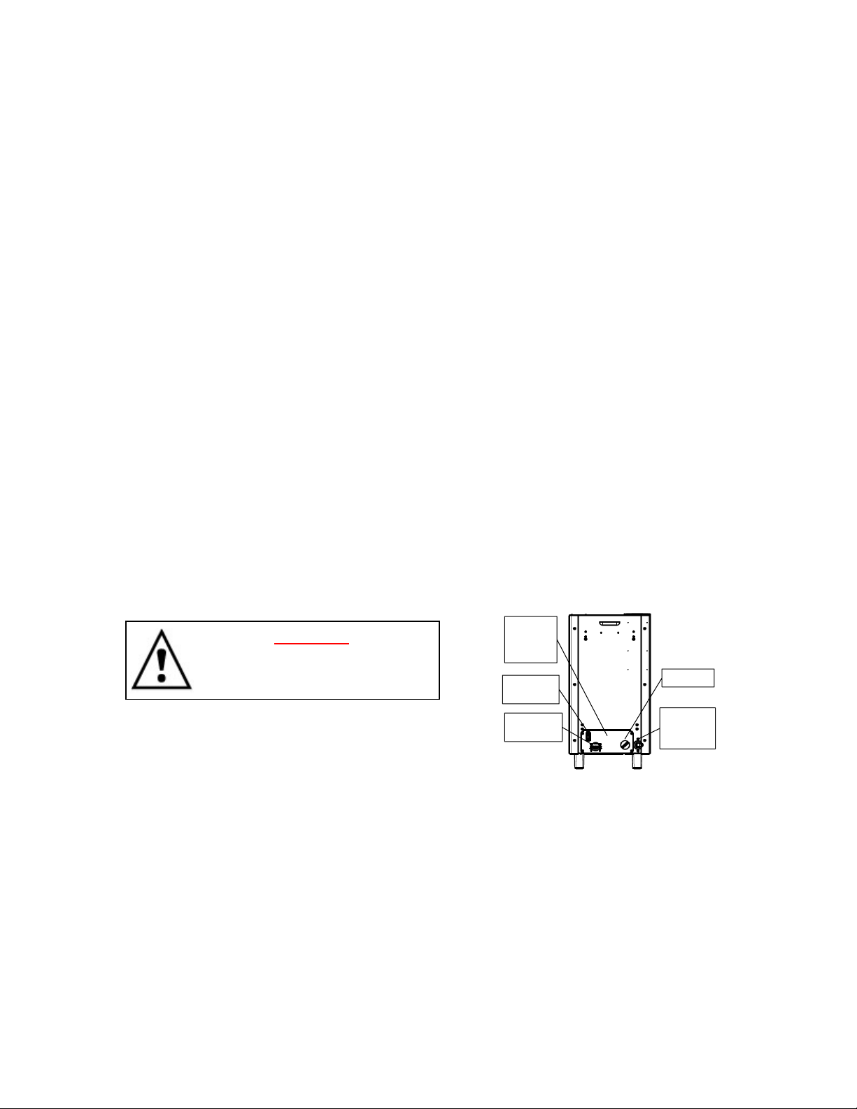
4. For 200-240 volt units: remove the lower utility slide out at the back of the equipment to access the
electrical connections. The utility slide must remain close to the unit, Note: it cannot be detached
completely.
5
Utility slide
on back
of brewer
Power
Switch
Electrical
Connection
Tank Drain
Water
Supply
Connection
Page 6

L2
Water Connection
1. Water inlet is a ¼ inch male flare fitting.
2. The brewer can be connected to a cold or hot water line. Cold water is preferred for best coffee flavor, but
hot water will allow for faster recovery times. High temperature water should not exceed 160°F/71°C.
3. Install a water shut off valve near the brewer to facilitate service. An in-line water filter should be used, it
should be installed after the water shut off valve and in a position to facilitate filter replacement.
4. Flush the water supply line and filter before connecting it to the brewer.
5. Verify that the water line will provide at least 1½gpm/(5.7lpm) per minute for the CBS-2131& CBS-2132 and
also that the water pressure is between 20-75 psig (138-517kPa).before connecting it to the brewer.
Electrical Connection – US & Canada
1. Verify that the actual voltage at the electrical service connection is compatible with the specifications on the
brewer’s serial number label. Install an electrical ground wire.
2. The temperature and water tank fill level are pre-set at the factory. There is no need to turn off the heaters
during the installation process. The heaters are disabled by the control board until the tank is full of water.
The heating process will start automatically when the tank has filled.
3. Most CBS-2131 equipment is factory equipped with a 120 V cord and plug. Some CBS-2131 and all CBS2132 have a terminal block for connecting the incoming power wires. Consult local codes to determine if a
cord and plug can be installed on factory supplied terminal block equipment, or if the unit must be hard
wired.
4. Plug in unit if the equipment has an attached cord & plug, or, wire into circuit for terminal block units. Note
that the plug is NEMA 5-15P or NEMA 5-20P (domestic).
5. A fused disconnect switch or circuit breaker on the incoming power line must be conveniently located near
the brewer, and its location and markings known to the operators.
6. The body of the brewer must be grounded to a suitable building ground. A ground lug is provided in the
brewer next to the power terminal block. Use 10 gauge copper wire for grounding.
7. Electrical connections must be secured in-place within the unit to meet national and local
standards.
Warning : To prevent
electrical shock, this
unit must be prope rly
grounded.
Electrical Configurations Terminal Block Diagram – US & Canada
WARNING—DANGER
Do not plug-in or electrically
energize this equipment, or attempt
operation without all covers in place
and all screws fastened
.
CBS-2131
120 volt models
Factory Configuration:
Attached cord 120 VAC, 3 wires
GROUND
LUG
L1 L2
N
Factory Configuration:
Terminal block for professional installation
(some)CBS-2131 and (all)CBS-2132
208-240 volt models
GROUND LUG
L1
N
L2 - NOT USED
For 120 volt
GROUND WIRE
!MUST BE INSTALLED!
CORD WITH
NEMA 5-15P or 5-20P
or without PLUG
120V 120V
GROUND WIRE
!MUST BE INSTALLED!
N
NOT USED
208-240V
NEW FETCO CONFIGURATIION METHOD!
6
Page 7

Final Setup
Final Setup
1. Turn on incoming water supply line and carefully inspect both inside and
outside of the brewer for leaks in all fittings and tubes
2. Turn on power.
3. Press the brewer’s main power switch (located on the lower right of the
back of the equipment)
4. Pre-check will display: "DC voltage calibration for pumps is
running…Please wait…Calibration is successfully done”. (15 seconds)
5. The water tank will begin filling. FETCO Home Screen #1 will read
“FILLING”.
6. When the water level rises and is sensed by the probe at the top of the
tank the heaters will activate
7. Heaters are automatically disabled until the tank is full.
8. While the water is heating Screen #2 “HEATING” will display and the
actual water temperature will be displayed.
9. After the water has reached the set temperature Screen #3 will display
“READY”
10. Review the Operating Instructions. Brew one full batch (water only) on
each side to confirm proper fill levels. The brewer is factory set with water
only (no coffee) to dispense the correct amount of water. If the actual
volume is slightly different from the programmed volume, fine tuning the
brewer may be necessary. See Calibrate Pumps in the OUTPUT section
in the PROGRAMMING section.
11. Re-attach the covers after one final inspection for leaks. Look closely in
the top of the brewer section at the dispense fittings during this
inspection.
Features of your FETCO Brewer
Touch-screen for brewer operation
Brew basket sensor (not accessible)
SD card interface port (Load & Save)
Hot Water Faucet
FETCO Home Screen #1 “FILLING”
FETCO Home Screen #2 “HEATING”
FETCO Home Screen #3 “READY
Locator removable for service access
Locator for airpot dispenser
(Two for CBS-2132)
Main power switch
Slide out back panel for service access
7
Page 8

p
Accessing batch and programming menu screens
Accessing batch and programming menu screens
DC voltage calibration for pumps is running
Please wait…
Calibration is successfully done.
Batch selection and brew operation menu screens
Å Tap FETCO HOME SCREEN to enter batch selection screen.
Hold down batch selector pennant to begin brew.
FETCO home screen
Programming menu screens
ÅFirst message on touchscreen display at powerup. This shows
only at “POWER ON”, when ON/OFF. The software is analyzing
and correcting any variations as a quality control feature.
Å FETCO home screen will display on completion
Tap left or right side batchesÆ
Operation screens
Touchscreen
MAIN POWER SWITCH
Located to lower right
side of back
anel
FETCO home screen
DC voltage calibration for pumps is running
Please wait…
Calibration is successfully done.
ÅFirst message on touchscreen display at powerup. This shows
only at “POWER ON”, when ON/OFF. The software is analyzing
and correcting any variations as a quality control feature.
Å FETCO home screen will display on completion
From power “OFF”ÆTurn main power switch to “ON”
Touch screen will illuminate, and pump voltage calibration will display
When Complete: FETCO HOME SCREEN will display
Immediately touch and hold finger to enter programming
In 5-8 seconds “PROGRAMMING” screen will appearÆ
8
Page 9
Operator Training
Review the operating procedures with whoever will be using the brewer.
Pay particular attention to the following areas:
1. Always pre-heat the dispensers before the first use of each day by filling them half way with hot water, and
letting them stand for at least 5 minutes.
2. Don't remove the brew basket from a coffee brewer until it has stopped dripping.
3. Make sure the dispenser is empty before brewing into it.
4. Show how to attach covers, close, and or secure the dispensers for transporting.
5. Show the location and operation of the water shut off valve as well as the circuit breaker for the brewer.
6. Steam from the tank will form condensation in the vent tubes. This condensation will drip into and then out of
the brew baskets. Up to 1/4 cup/118cc discharging overnight is possible. Place an appropriate container
under each brew basket when not in use.
7. We recommend leaving the power to the brewer on overnight. The water tank is well insulated and very little
electricity is used to keep the tank hot. Leaving the brewer in the “ON” position will also avoid delays at the
beginning of shifts for the brewer to reach operating temperature.
Cleaning & Maintenance
After Each Brew:
1. Dispose of grounds and rinse brew basket.
2. Never strike a brewbasket or hit it against a hard surface.
This will damage the brew cone, and may damage the brewbasket support rails
3. Rinse dispensers before reuse.
Every Day:
1. Wash brew basket with hot sudsy water.
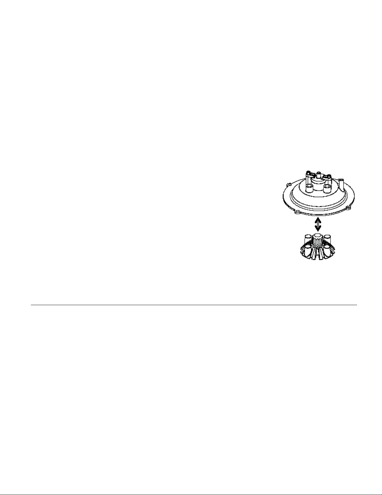
2. Pull CSD from the spray head, it is magnetically attached. Use gloves or a heavy towel. Æ
Wash off any film and reattach. Use vinegar if limescale filming is present.
3. Clean dispensers with hot suds water and a brush, rinse and air dry.
4. Use only a soft cloth and hot suds on the outside to avoid scratches. Never use abrasives
which will scratch surface.
Weekly
1. Use a commercial coffee dispenser cleaner such as URNEX™, TABZ™, DIP-IT™ or Squeak 'n Clean™.
2. Carefully Follow the instructions supplied with the cleaning product
3. Never use spray cleaners, solvent, solvent based cleaner or petroleum based polish anywhere on dispensers
Safety notes
1. Professional installation is required. This appliance is manufactured for commercial use only.
2. Operation requirements and maintenance for commercial cooking appliances differ from household appliances.
3. Operators must be trained for this equipment and must understand the use, maintenance and hazards.
4. Do not attempt to move hot beverage equipment once it is filled. Drain equipment before moving.
5. CBS-2130 series coffee brewers prepare up to 3 liters/1 gallon of coffee or tea in a single batch using very hot
water. For safety, the brew basket is locked and may be serviced 5.5 minutes after starting the brew. The
factory set brew (default) time is 5.5 minutes with the brew basket locked for safety from start of brew.
! Æ Never attempt to defeat or override a brew basket locking feature.
Warning
1. Turn off power before any cleaning procedure, including wiping the exterior for appearance reasons.
2. Dry the exterior, especially the face panel, before turning on power.
3. Do not apply any type of spray cleaner on the face panel of this equipment.
4. Never use solvent or solvent-based cleaner or petroleum based polish anywhere on this equipment.
5. Dry the face of the touch pad before turning on power
6. Do not electrically energize this equipment or attempt operation without all covers in place and all screws fastened.
7. Unplug machine before disassembly or servicing.
9
Page 10

Operating Instructions
ÆQuick brewer setup NOTES
Install plumbing and electrical utilities.
Turn rear power switch “ON”.
Brewer hot water tank will fill in 4-8 minutes.
Heater(s) activate when tank is full
Initial heating will be 15-30 minutes
Tank displays “ ▪ READY” when filled & 200°F/93°C is reached
Brewer is ready to brew when “▪ READY” is displayed
-See Installation Section in this guide
-Located on back, lower right side
-Ready screen will display ”▪FILLING”
-Ready screen will display ”▪HEATING”
-Place dispenser under brewbasket(s)
to collect any overflow and condensate
-Best results if brewer remains “ON”
Brewing
ÆTo brew a single 3 liter coffee batch, using default recipe NOTES
FETCO CBS-2130 series equipment is factory calibrated and preloaded with recipes and is ready to brew.
Place 13”X5” paper filter in brew basket
Add 3-8 ounces (85 – 227 g) of ground coffee
Insert loaded brewbasket into brewer rails
Have empty dispenser under brewbasket
Tap “▪ READY” screen to enter the batch selection menu
-FETCO Product # F002 or any 13”X5”
-Weights given are only suggested
-Brewbasket(s) must be in place
-Use the convenient locator guide
-A long duration “TAP” with fingertip
Touch a top batch key for “REGULAR 1”
Brewer will brew and display the icon for the function step it is in
On dual side brewer, touch other side to access batches for brewing
Batch will complete brewing in 5 ½ minutes
Touch the “Ready” screen
anywhere briefly to activate
(CBS-2131)
(CBS-2132)
Touch and hold finger on
selection pennant for about two
seconds to start brew
CBS-2132 selection
for brewing on right,
left or both sides.
Touch batch pennant
to access menu
-Touch batch pennant with fingertip
-Icon may be toggled for information
-Right to left side switching by touch
-Brew time: 4 minutes+1½ min. drip out
10
Page 11

Brewing-shown by touchscreen
Brewer screens displayed for brewing NOTES
CBS-2131 CBS-2132
“READY SCREEN”
Tap screen to display
menus
Unit displays four
preprogrammed batch
buttons per side. CBS-
2132 has right and left
ÅCBS-2131
CBS-2132 Æ
Select and hold one button
for 2 seconds
Brew started
(in prewet)
ÅCBS-2131
CBS-2132 Æ
Note: there are three “BREW AT
TEMPERATURE DEFINITONS”. The “Brew
at temperature default routine is shown below.
Brew basket sensor
enabled.
Unit is brewable only when
brebasket is in place.
(option may be disabled by
user)
Brew at tempertaure
enabled: brew will start
when tank temperature
reaches he set point
Both sides of CBS-2132
brewing simaltanously.
Brewing
ÅCBS-2131
CBS-2132 Æ
Brewing
ÅCBS-2131
CBS-2132 Æ
Brew completed
(in drip delay)
ÅCBS-2131
CBS-2132 Æ
Both sides of CBS-2132
brewing simaltanously.
Both sides of CBS-2132
brewing simaltanously.
Left side completing drip
delay
CBS-2132 right side
completing drip delay, left
side ready for next brew
11
Page 12

-The FETCO CBS-2130 brewers have four brew batch menus per side.
They are preprogrammed with basic settings that will operate the equipment as purchased.
There are two batches each marked “Regular” and two marked “Decaf”
-Most operators prefer a full batch and half batch setting for regular and decaf or specialty coffees. These will need
to be programmed by the operator
-Settings are adjustable and the names can be changed. -Batch 1 & 4 cannot be disabled.
Menu screen displayed
(FETCO “HOME” screen)
Programming- operator access programming
Accessing
Programming
Turn unit “OFF”
After 10 second delay:
Pre-check will display: "DC
voltage calibration for pumps is
running…Please wait…Calibration
is successfully done”.
Turn unit “ON”
“HOME" Screen on left will
appear
Å
Immediately place finger on
screen and “HOLD”
Screen on right will appear
Æ
Menu screen displayed
<
<
PROGRAM
Batch 1 Left
EXIT
<< >>
T
ÅTop line is programming
>
category
>
Å Second line displays
items for programming
Right and left hand arrows
will scroll to the screens that
display “Program, General,
Inputs, Outputs and Other”.
Down arrow enters the
individual programming items
shown below
Accessing
Programming menu
screens
Programming-category screens: Menu Tree
Programming category screens
To enter: Turn unit “OFF”, After 10 second delay, turn unit “ON”, (Home Screen will appear),
Immediately place finger on screen and “HOLD” PROGRAM
Use right/left and down arrows to travel through programming. “EXIT” saves settings
Screen (first below) will appear.
Programming Category
PROGRAM
Items for Programming Items for Programming Items for Programming
Batch 1 LEFT*
Batch 2 Left**
Batch 3 Left **
Batch 4 Left **
Batch 1 RIGHT*
Batch 2 Right **
Batch 3 Right **
Batch 4 Right **
Batch Copy
Programming Category Programming Category Programming Category
GENERAL
Tank Temp
Brew At Temp
Unit of Meas.
Volume
ECO Mode
Logo Timeout
Brew B.Sensor
INPUTS OUTPUTS
Display Inputs Left Pump
Calib Touch Scr L.Bypass Pump* Display Errors
12
Programming Category
Items for
Programming
Right Pump
R.Bypass Pump* Copy Program
Fill Valve
Heater
Screen
*
Bypass option is only on
1 gallon airpot version
Items for Programming
OTHER
Error Codes
Reset Errors
From SD to B
From B to SD
Upload Logo
Res to Factory
Firmware
Page 13

Menu Features: Batch Parameters
PROGRAM Programming Items Factory set Default Programming Range Notes
Batch 1 LEFT*
• Batch Summary
• Batch Name
• Batch Volume
• Brew Time
• Spray Pattern
• Nr Of Pulses
• Prewet Perc.
• Prewet Delay
Batch 2 Left**
• Bypass Perc.
• Drip Delay
**Batch 2-4—Right and Batch2-4—Left may be individually selected-or-entirely deleted
• Batch ON/OFF
• Batch Summary
• Batch Name
Batch 3 Left **
Batch 4 Left **
Batch 1 Right *
Batch 2 Right **
Batch 3 Right **
Batch 4 Right **
Batch Copy
Copy?
*Batch 1&4 cannot be disabled. (CBS-2132); *Batch 1 cannot be disabled. (CBS-2131) **Batch can be disabled, and removed from display
• Batch Volume
• Brew Time
• Spray Pattern
• Nr Of Pulses
• Prewet Perc.
• Prewet Delay
• Bypass Perc.
• Drip Delay
(See Batch 2-Left)
(See Batch 2-Left)
(See Batch 1-Left)
(See Batch 2-Left)
(See Batch 2-Left)
(See Batch 2-Left)
Copy From Batch L1 L1-L4;R1-R4
Copy To Batch L1 L1-L4;R1-R4
Display Summary
Regular 1(-16)
3.05 liter
[ 1.0-4.7]
4:00 mm:ss
Wide
8
0%
0:00 mm:ss
0%
1:30 mm:ss
ON
Choose from list:
Regular1
3.03 liter
|_________
0.94 4.73
4:00 mm:ss
[]___________|
|_____
2:00 10:00
[]______________|
|__
Wide Middle Narrow
[]___________|
|_____
1 30
[]_______________|
|_
0 15
1:30 mm:ss
[]________________|
|
0:00 1:00
[]_______________|
|_
0 40
1:30 mm:ss
[]___________|
|_____
0:30 5:00
|_________
0.94 4.73
[]________|
Wide
8
0 %
0 %
ON
[]________|
(Regular 1-16)
-OR- Write: any name
Bypass option is only on 1
gallon airpot version
Display Summary
Regular 1
3.03 liter
[ 0.94-4.73]
4:00 mm:ss
Wide
8
0%
0:00 mm:ss
0%
1:30 mm:ss
Regular 1-16;Write own name
ON
[]______________|
|___
ON OFF
4:00 mm:ss
[]___________|
|_____
2:00 10:00
Wide Middle Narrow
0:00 1:00
0:
Wide
[]______________|
|__
8
[]___________|
|_____
1 10
|_
[]________________|
|
|_
0 %
[]_______________|
0 15
0:00 mm:ss
0 %
[]_______________|
0 40
1:30 mm:ss
[]_________|
|_____
30 5:00
Bypass option is only on 1
gallon airpot version
L1ÆL2?
(example)
|_______________
YES NO
NO
[]__|
13
Page 14

g(°F)
GENERAL
Tank Temp.
Brew at Temp.
Units of Meas.
Logo Timeout
Brew B. Sensor
Programming
Items
200°F
“OFF” allows
brewing at any
temperature.
• Temperature
• Volume
1:00 mm:ss
Factory set
Default
AUTO
°F
Liters
Programming Range
|______________[]___|
180 207
|____________[]___|
OFF ON AUTO
|___[]____________|
|_____________[]__|
|_[]_______________|
0:00 5:00
NORMAL
NORMAL OVERRIDE
(display)
200 °F
AUTO
°F
°F °C
Liters
Gallons Liters
1:00 mm:ss
NORMAL
|__[]____________|
Notes
Correction for high
altitude below
SEE NOTE BELOW!
INPUTS
Display Inputs
Cal. Touch Scr
Chart to correct for boiling point for altitude
in tank water temperature.
Altitude (ft.)
0 200 212.0
500 200 211.1
1000 200 210.2
2000 200 208.4
2500 200 207.5
3000 200 206.6
3500 197 205.7
4000 195 204.8
4500 194 203.9
5000 194 203.0
5500 193 202.0
6000 192 201.1
6500 191 200.2
7000 190 199.3
7500 188 198.3
8000 187 197.4
Suggested
Settin
Programming
Items
• Input
Summery
Boiling
point (° F)
Factory set
Default
Calibrate
Programming Range
(display)
Brew Basket Sensor
High Liquid Level probe
High Tank Temperature Probe
Lower Tank Temperature Probe
SD Card Recognized
USB Drive Recognized
________________[]____
YES NO
Calibrate
USB is for factory
Follow directions on
the touch screen
BREW AT TEMPERATURE DEFINITONS
BREW AT TEMP: AUTO
(DEFAULT: FACTORY PROGRAMMED INTO BREWER)
This allows the “BREW START” to active. If the hot water
tank is at the selected temperature—the brew will start.
If the temperature is too low, the brewer will wait until the
proper temperature is reached. A screen (example to the
right) will display showing a thermometer icon and the tank
temperature.
IMPORTANT: ALWAYS have dispenser(s) under the brew
baskets when in the BREW AT TEMP mode.
BREW AT TEMP: ON USER SELECTABLE
“BREW START” Batch Section Buttons will not be
accessible until tank temperature is at set point.
The “BREW START” screens with the Batch Section
Buttons become accessible when hot water tank is at the
selected temperature. The screen at right displays when
the “BREW AT TEMP” is selected.
BREW AT TEMP: OFF USER SELECTABLE
Allows brewing at any temperature above 179°F/82°C. (Not recommended)
.
14
Notes
setup only
If Yes
:
Page 15

OTHER
Error Codes
Copy
Program
Upload Logo
Res to
Factory
Counters
Firmware
Programming
Items
• Display Errors (Codes)
• Reset Errors
• From SD to B.
• From B to SD
Factory set
Default
(Reset)
SDÆ Brewer
BrewerÆ SD
Upload Logo
Reset to default
• Display
Counters
-OR-
• Reset
Counters
• Reset
Counters
• Firmware
Version
-Software type
• Update
Firmware
Counters
Display Total
Counters
Reset All
Counters
Firmware Version
UPDATE
Programming Range
(display)
1:
2:
3:
|_______________[]____|
|________________[]____
|________________[]____|
|________________[]____|
|________________[]____|
Left Brews
Left Brew activated
Left Brew [liters]
Left Bypass Activated
Left Bypass [liters]
Right Brews
Right Brew activated
Right Brew [liters]
Right Bypass Activated
Right Bypass [liters]
Fill valve Activated
Fill Valve [liters]
Heater Activated
Heater “on” time
Touch To Return
|________________[]____|
|________________[]____|
Reset
YES NO
SDÆ Brewer
YES NO
BrewerÆ SD
YES NO
UPLOAD LOGO
Are you sure
YES NO
Reset to Default
Are you sure
YES NO
All Counters
Reset All Counters
Are you sure
YES NO
SW ver. 1.0.2A
HW ver
BL ver.1.0.1
QP ver. 4.5.01
UPDATE
YES NO
Notes
Chart is below
!!Errors must be
corrected and cleared!!
Setup upload
------------------------------------------------------------------------
Please insert SD card with
------------------------------------------------------------------------
Please insert SD card with
sufficient space
Please insert SD
card with logo file!
overwrites all user
setup, incl. user logo.
0
0
0
0
0
0
Resetting will
0
restart counter
0
from zero
0
0
0
0
0
0
Displays firmware
------------------------------------------------------------------------
Please insert SD card with
----
the setup data!
Setup download
----
(≥2GB)
Completely
version
Firmware upload
----
the firmware file!
ERROR CODES
Error code 50: Shorted temperature probe
Error code 51: Open temperature probe
Error code 100: Initial Fill Error. Initial fill time was more than 4 minutes after power up.
Error code 101: Error on refill
Error code 102: Unwanted fill; possible leak
Error code 103: Liquid level probe fault
Error code 201: Heater open, high limit thermostat, or Solid State Relay (SSR) fault
15
Page 16

OUTPUTS
Left Pump
’’ ’’ ’’ ’’
L.Bypass Pump*
’’ ’’ ’’ ’’
Right Pump
’’ ’’ ’’ ’’
R.Bypass Pump*
’’ ’’ ’’ ’’
Fill Valve
Heater
Screen
Programming
Items
• Left Pump Test (Press to test)
• L. Pump Calib
• Left BP Pump
Test
• L. BP Pump
Calib
• Right Pump Test (Press to test)
• R. Pump Calib
• Right BP Pump
Test
• R. BP Pump
Calib
• Fill Valve Test (Press to test)
• Heater Test (Press to test)
• Screen Contrast Contrast
• S. Brightness
Factory set
Default
Calibrate
*Flow Rate
(Press to test)
Calibrate
*Flow Rate
Calibrate
*Flow Rate
(Press to test)
Calibrate
*Flow Rate
Brightness
*Bypass option is only on 1 gallon airpot version
*How to calculate flow rate
Measured Æ
Set Point Æ
If flow rate setting is 0.49
Then new flow rate is
0.49 X 0.96=0.47
By entering the new flow rate number
into the brewer, the software will
correct the discrepancy in the pump.
2.90
———
3.00
Programming Range
(display)
TEST
Press To Test
|_________[]________|
0.39 0.59
Press To Test
|_________[]________|
0.39 0.59
Press To Test
|_________[]________|
0.39 0.59
Press To Test
|_________[]________|
0.39 0.59
Press To Test
Press To Test
|____________[]____|
|____________[]____|
=
0.96
0.49
TEST
0.49
TEST
0.49
TEST
0.49
TEST
TEST
8
1 10
8
1 10
Notes
Runs pump to verify
flow. Have container
under brewbasket!
Factory or service use
for flow rate
Runs pump to verify
flow. Have container
under brewbasket!
Factory or service use
for flow rate
Runs pump to verify
flow. Have container
under brewbasket!
Factory or service use
for flow rate
Runs pump to verify
flow. Have container
under brewbasket!
Factory or service use
for flow rate
Operates fill valve.
Have container under
both brewbaskets!
Energizes Heater(s)
Use for servicing.
16
Page 17

Hot water convenience tap
1. The CBS-2130 coffee brewers include a hot water convenience tap for single cup beverage purposes.
2. Single use delivery volume should not exceed maximum 16fl.oz/473cc.
3. Water dispensed from this faucet is very hot, up to 205°F/96°C
Adjustable spray pattern
This FETCO equipment features digitally adjustable spray patterns for perfect penetration
FETCO CBS-2131 and CBS-2132 coffee brewers feature digitally adjustable spray patterns for perfect penetration.
All batches can be set for wide, middle or narrow spray patterns of the hot brew water that showers the coffee bed
in the brewbasket. The turbulence created by the spray pattern combined with variable pulses is infinitely
adjustable for desired flavor extraction of individual roasts and grinds of any coffee variety.
The default setting for all batches is WIDE. The brewer software calculates and corrects to achieve proper volume
based on the flow rate changes of the spray pattern.
Error Codes
Code Description Possible Cause Corrective Action
050 Shorted temperature probe Probe failure. Replace probe.
051 Open temperature probe.
Initial Fill Error. Initial fill
100
time was more than 4
minutes after power up.
Error on refill
101
Tank did not refill within 3
minutes.
102 Unwanted fill;
103 Liquid level probe fault
Heater open, high limit
201
thermostat, or Solid State
Relay (SSR) fault
INSERT
Bad probe
connection, or
probe failure.
Water supply flow
rate is too low.
Water supply flow
rate is too low.
Possible leak in
tank, fitting, or
valve.
Probe fouled or
shorts
SSR, High Limit,
or heating
element failure.
Brewbasket must
be in place
Check all connections.
Replace probe if necessary.
Watch for short potting
during brew cycle.
Investigate cause of low flow
rate. (Clogged water filter...)
Watch for short potting
during brew cycle.
Investigate cause of low flow
rate. (Clogged water filter…)
Check inside of machine for
leaks.
Clean, check all
connections. Replace probe
if necessary.
Check and replace heating
elements if necessary.
Insert brewbasket
BREW
BASKET
CLEAR FAULT, make
repairs as required
Below is the only way to
clear error codes
1) Enter
“PROGRAMMING”
2)Scroll left to “OTHER”
3)Scroll down to
“ERROR CODES”
4)Scroll down to “Display
Errors”
5)Scroll left to “Reset
Errors”
6)Scroll down to “Reset”
7)Follow directions
shown on screen.
Toggling ON/OFF switch
will not
Error codes must be
cleared!
How to Clear
Error Codes
clear error codes.
Designs, materials, specifications, physical dimensions, firmware and software protocol for equipment or replacement parts are subject to review and change by FETCO without notice
17
Page 18

Airpot use instructions and cleaning
Dispenser Diagram
D041 (3 liter) and
®
D063 (1 gallon) Airpot
DESCRIPTION : Dispenser Diagram
The FETCO D041 (3 liter) and D063 (1 gallon) airpots are lever type, air pressure evacuated
beverage dispenser featuring double-wall, vacuum insulated construction.
The hermetically sealed vacuum double-wall construction provides excellent heat or cold
retention, while the stainless steel outer and inner liners provide robust durability.
PARTS :
Locking Tab
Lever
Bellow Cap
Bellow
Bellow Cap Plate
Spout Tube
Drip-Through
Down Tube
Lip Release Button
18
Page 19

Dispenser Operation Instructions
D041 (3 liter) and
®
D063 (1 gallon) Airpot
To Fill :
Set brewer to dispense the
1
proper amount into the
airpot :
3 liters (FETCO D041)
-or-
1gallon (FETCO D063)
To Dispense:
After the brew cycle is
1
completed:
Remove the airpot from
under the brewbasket and
close the lid.
Squeeze the Lid Release
2
Buttons to release the lid.
Swing the lid completely
backwards
Lift the handle up until the
2
Lever Lock drops into
position, and engages the
pump mechanism.
Place the airpot under the
3
brewer against the airpot
dispenser Locator (if
featured).
Align the center of the
airpot Drip-Through with
the outlet of the
brewbasket.
Push the lever downwards
3
multiple times to dispense
the desired amount
19
Page 20

4
Dispenser Cleaning & Maintenance
D041 (3 liter) and
®
D063 (1 gallon) Airpot
To Clean :
Squeeze the Lid Release
1
Buttons to release the lid.
Press the Lid Detach Button
that will completely detach
the lid.
Remove the Lid Cover.
Remove the Drip-Through
2
Detach the Down-Tube
and the Spout-Tube.
Clean with warm water,
detergent and a brush.
Proprietary airpot cleaners
may also be used.
Carefully remove the
3
bellows Cap.
Handling the parts gently,
clean the Bellows,
Bellows Cap, and Bellow
Cap Plate with warm
water, and non-abrasive
mild detergent.
Clean the interior of the tank
with warm water, detergent
and a brush. Proprietary
airpot cleaners may also be
used
.
Do not put the airpot into
an automatic dishwasher.
Do not allow solutions
containing chlorine to
remain in tank.
Clean the exterior of the
5
with warm water, non-
unit
abrasive mild detergent.
Do not submerge the unit
in water
6
C4H9OCH2CH2OH
Do not use petroleum
based or organic cleaners
on food equipment.
Never use cleaners or
polishes formulated with
the solvent diethylene
glycol butyl ether(DGBE)
on any equipment.
20
Page 21

FETCO® CBS-2130
COFFEE BREWING SYSTEM
Complete Commercial Parts Listing
For CBS-2131 and CBS-2132 Model Range
Includes types for the 3 liter and 1 gallon airpot dispensers
NEW September, 2012
Please see our website-www.fetco.com for the most up to date listings and additional parts and service information
Designs, materials, specifications, physical dimensions, firmware and software protocol for equipment or replacement parts are subject to change without notice.
21
Page 22

Parts diagrams, bill of materials lists
22
Page 23

Drawing 1101.00128.00 CBS-2131ASSEMBLY, 1gallon NO BYPASS, 2.3kW/120VAC
Ref# Qty Part number Description
1 1 1111.00030.00 WELDMENT BODY, CBS-2131
2 2 1024.00049.00 EDGE PROTECTOR, 7.00"LG, CBS-2130
3 3 1086.00004.00 BUSHING, SNAP, 1" MOUNTING HOLE
4 1 1024.00017.00 O'RING, 3.739" ID X 0.070" CS, 70 DURO, BUNA "N", FDA
5 1 1102.00183.00 SPRAY HOUSING ASSEMBLY, CBS-2130
6 4 1083.00010.00 WASHER, #10 SCREW W/NEOPRENE-BONDED SEAL
7 8 1084.00006.00 NUT, 8-32 18-8 HEX MACHINE SCREW
8 1 1102.00113.00 SWITCH, REED, ASSEMBLY
9 4 1029.00006.00 #4-40 NYLON FINGER NUT
10 1 1071.00010.00 FAUCET HPSC-BR-8 REGULAR HANDLE
11 1 1031.00003.00 FITTING, BARB 3/8'ID x 1/4" FPT
12 1 1057.00043.00 SOLENOID VALVE, SINGLE, 180 DEG, 24VDC
13 1
14 2 1083.00005.00 WASHER, M4 18-8 INTERNAL TOOTH LOCKWASHER
15 2 1082.00010.00 SCREW, M4x10 ZINC PLATED PAN PHILLIPS MACHINE
16 1 1102.00164.00 ADAPTER ASSY, 3/4" BSP X 1/4 SAE FLARE
17 1 1104.00043.00 TANK ASSY, 2300W/120VAC, CBS-2131, GROMMETS
18 1 1112.00163.00 WELDMENT TANK LOCK BRACKET, CBS-2100
19 4 1083.00011.00 WASHER, #8 SCREW SIZE, INTERNAL TOOTH LOCK
20 2 1082.00023.00 SCREW, #8-32 X 3/8 TRUSS HD PHIL., MACHINE
21 1 1102.00187.00 PUMP BRACKET AND HOLDER ASSEMBLY
22 9 1086.00003.00 UNICLAMP, 15.9 HOSE OD CLAMP
23 1 1025.00063.00 TUBE, 5/8'OD X 3/8"ID X 8.50"LG
24 1 1102.00181.00 ASSEMBLY BACK PANEL, CBS-2130
25 11 1082.00017.00 SCREW, # 6-32 X 1/2" TRUSS HD PHIL., MACHINE
26 1 1023.00147.00 PLUG, TANK SERVICE DRAIN FOR 18GA AND UP BODY
27 1 1024.00040.00 CARD PLUG, HWD-2100
28 1 1102.00190.00 ASSEMBLY FRONT PANEL, CBS-2100
29 4 1082.00058.00 SCREW, # 8-32 X 5/8, FLAT HD, PH, 18-8 SS
30 1 1102.00182.00 ASSEMBLY, LOCATOR CBS-2130
31 1 1082.00065.00 SCREW #8-32 X 1 1/2", FLAT HD PH, 18-8 SS
32 1 1023.00159.00 CORNER INSERT
33 1 1112.00168.00 WELDMENT, TOP COVER, CBS-2131
34 1 1402.00034.00 HARNESS, HIGH AMP, CBS-2131
35 1 1402.00035.00 HARNESS, LOW AMP, CBS-2131
36 1 B012280B1 BB ASSY, 13"X5", .280" DIA. HOLE, BLK HNDL
37 1 1024.00052.00 CONNECTOR, BREW PUMP
38 1 1086.00002.00 CLAMP, HOSE, SIZE "G" NYLON
39 1 1055.00001.00 PUMP, HOT LIQUID
40 1 1025.00012.00 TUBE, 5/16'OD X 3/16"ID X 11.00"LG
41 1 1025.00061.00 TUBE, 9/16'OD X 5/16"ID X 2.75"LG
42 1 1029.00002.00 FITTING, HOSE BARB TEE, SIZE 3/8" , NYLON
43 1 1025.00058.00 TUBE, 9/16'OD X 5/16"ID X 25.00"LG
44 1 1025.00060.00 TUBE, 9/16'OD X 5/16"ID X 3.25"LG
45 1 1083.00009.00 WASHER, #6 SCREW , INTL TOOTH LOCKWASHER
46 1 1084.00010.00 NUT, HEX, #6-32, UNDERSIZED, ZINC PLATED
47 1 1025.00006.00 TUBE, VENT SUPPORT, 5/16" OD X 3/16" ID X 1/2" LG
48 1 1025.00064.00 TUBE, 1/2 OD X 1/4 ID X 9.00 LG
49 1 1013.00073.00 TUBE, 5/16" OD, 1" LONG
50 1 1046.00006.00 LABEL, WARNING, "HOT WATER FAUCET"
51 1 1044.00004.00 LABEL, DANGER, HIGH VOLTAGE
52 1 1046.00003.00 LABEL, CSD WARNING, 1.5" X 5.0"
53 4 1023.00163.00 LEG BODY, CBS-2130
54 4 1083.00021.00 WASHER, 1/4" SCREW SIZE, SPRING LOCK
55 4 1112.00158.00 WELDMENT, LEG ROD, CBS-2130
56 4 1021.00017.00 LEG INSERT THREADED, CBS-2130
23
Page 24

24
Page 25

Drawing 1101.00127.00 CBS-2131ASSEMBLY, 3 Liter NO BYPASS , 2.3kW/120VAC
Ref# QTY PART NO DESCRIPTION
1 1 1111.00030.00 WELDMENT BODY, CBS-2131
2 2 1024.00049.00 EDGE PROTECTOR, 7.00"LG, CBS-2130
3 3 1086.00004.00 BUSHING, SNAP, 1" MOUNTING HOLE
4 1 1024.00017.00 O'RING, 3.739" ID X 0.070" CS, 70 DURO, BUNA
5 1 1102.00183.00 SPRAY HOUSING ASSEMBLY, CBS-2130
6 4 1083.00010.00 WASHER, #8 SCREW SIZE W/NEOPRENE- BONDED SEAL
7 8 1084.00006.00 NUT, 8-32 18-8 HEX MACHINE SCREW
8 1 1102.00113.00 SWITCH, REED, ASSEMBLY
9 4 1029.00006.00 #4-40 NYLON FINGER NUT
10 1 1071.00010.00 FAUCET HPSC-BR-8 REGULAR HANDLE
11 1 1031.00003.00 FITTING, BARB 3/8'ID x 1/4" FPT
12 1 1057.00043.00 SOLENOID VALVE, SINGLE, 180 DEG, 24VDC
13 1
14 2 1083.00005.00 WASHER, M4 18-8 INTERNAL TOOTH LOCKWASHER
15 2 1082.00010.00 SCREW, M4x10 ZINC PLATED PAN PHILLIPS MACHINE
16 1 1102.00164.00 ADAPTER ASSY, 3/4" BSP X 1/4 SAE FLARE
17 1 1104.00043.00 TANK ASSY, 2300W/120VAC, CBS-2131, GROMMETS
18 1 1112.00163.00 WELDMENT TANK LOCK BRACKET, CBS-2100
19 4 1083.00011.00 WASHER, #8 SCREW SIZE, INTERNAL TOOTH LOCK
20 2 1082.00023.00 SCREW, #8-32 X 3/8 TRUSS HD PHIL., MACHINE
21 1 1102.00187.00 PUMP BRACKET AND HOLDER ASSEMBLY
22 9 1086.00003.00 UNICLAMP, 15.9 HOSE OD CLAMP
23 1 1025.00063.00 TUBE, 5/8'OD X 3/8"ID X 8.50"LG
24 1 1102.00181.00 ASSEMBLY BACK PANEL, CBS-2130
25 11 1082.00017.00 SCREW, # 6-32 X 1/2" TRUSS HD PHIL., MACHINE
26 1 1023.00147.00 PLUG, TANK SERVICE DRAIN FOR 18GA AND UP BODY
27 1 1024.00040.00 CARD PLUG, HWD-2100
28 1 1102.00190.00 ASSEMBLY FRONT PANEL, CBS-2100
29 4 1082.00058.00 SCREW, # 8-32 X 5/8, FLAT HD, PH, 18-8 SS
30 1 1102.00182.00 ASSEMBLY, LOCATOR CBS-2130
31 1 1082.00065.00 SCREW #8-32 X 1 1/2", FLAT HD PH, 18-8 SS
32 1 1023.00159.00 CORNER INSERT
33 1 1112.00168.00 WELDMENT, TOP COVER, CBS-2131
34 1 1402.00034.00 HARNESS, HIGH AMP, CBS-2131
35 1 1402.00035.00 HARNESS, LOW AMP, CBS-2131
36 1 B012280B1 BB ASSY, 13"X5", .280" DIA. HOLE, BLK HNDL
37 4 1073.00008.00 FOOT, CBS-2130
38 4 1082.00066.00 SCREW 1/4-20 X 1/2", SOCKED HD CUP
39 1 1024.00052.00 CONNECTOR, BREW PUMP
40 1 1086.00002.00 CLAMP, HOSE, SIZE "G" NYLON
41 1 1055.00001.00 PUMP, HOT LIQUID
42 1 1025.00012.00 TUBE, 5/16'OD X 3/16"ID X 11.00"LG
43 1 1025.00061.00 TUBE, 9/16'OD X 5/16"ID X 2.75"LG
44 1 1029.00002.00 FITTING, HOSE BARB TEE, SIZE 3/8" , NYLON
45 1 1025.00058.00 TUBE, 9/16'OD X 5/16"ID X 25.00"LG
46 1 1025.00060.00 TUBE, 9/16'OD X 5/16"ID X 3.25"LG
47 1 1083.00009.00 WASHER, #6 SCREW , INTL TOOTH LOCKWASHER
48 1 1084.00010.00 NUT, HEX, #6-32, UNDERSIZED, ZINC PLATED
49 1 1025.00006.00 TUBE, VENT SUPPORT, 5/16" OD X 3/16" ID X 1/
50 1 1025.00064.00 TUBE, 1/2 OD X 1/4 ID X 9.00 LG
51 1 1013.00073.00 TUBE, 5/16" OD, 1" LONG
52 1 1046.00006.00 LABEL, WARNING, "HOT WATER FAUCET"
53 1 1044.00004.00 LABEL, DANGER, HIGH VOLTAGE
54 1 1046.00003.00 LABEL, CSD WARNING, 1.5" X 5.0"
25
Page 26

Drawing 1104.00043.00 TANK ASSY, 2300W/120VAC, CBS-2131, GROMMETS
Ref# QTY PART NO DESCRIPTION
1 1 1114.00066.00 WELDMENT TANK CBS-2131, GROMMET DESIGN
2 4 1024.00050.00 GROMMET, SILICONE, 11.4mm ID
3 1 1024.00051.00 GROMMET, SILICONE, BLANK
4 2 1024.00053.00 GROMMET, SILICONE, LL & TEMP. PROBES
5 1 1003.00005.00 BRACKET, ONE SHOT THERMOSTAT
6 1 1053.00003.00
7 2 1083.00009.00 WASHER, #6 SCREW , INTL TOOTH LOCKWASHER
8 2 1084.00010.00 NUT, HEX, #6-32, UNDERSIZED, ZINC PLATED
9 1 1003.00140.00 ALUMINUM BRACKET FOR SSR
10 1 1052.00014.00 ASSEMBLY RELAY, SOLID STATE, 25A/230V
11 2 1081.00042.00 STANDOFF, 6-32 x1.25 LG.,1/4 HEX WIDTH
12 1 1107.00021.00 HEATER ASSEMBLY, IMMERSION 1500W/120VAC
12 1 1107.00022.00 HEATER ASSEMBLY, IMMERSION 1700W/120VAC
12 1 1107.00019.00
12 1 1107.00020.00
12 1 1107.00018.00 HEATER ASSEMBLY, IMMERSION 3000W/240VAC
13 1 1112.00002.00 PROBE WELDMENT, WATER LEVEL 2.25" LG
14 1 1102.00161.00 PROBE ASSEMBLY, TEMP. AND LLC, HWD-2100
15 1 1024.00007.00 O-RING, DASH #344, TANK COVER
16 1 1102.00007.00 TANK COVER ASSEMBLY
17 1 1023.00167.00 FITTING, BREW, GROMMET DESIGN
18 1 1023.00168.00 FITTING, HOT WATER, GROMMET DESIGN
19 1 1023.00166.00 FITTING, COLD WATER INLET, GROMMET DESIGN
20 1 1022.00056.00 TANK INSULATION, CBS-2131e, GROMMET DESIGN
THERMOSTAT, SINGLE SHOT, 240V/40A
HEATER ASSEMBLY, IMMERSION 2300W/120VAC
HEATER ASSEMBLY, IMMERSION 2300W/240VAC
26
Page 27

27
Page 28

Drawing 1101.00132.00 CBS-2132-3 Liter NO BYPASS 2 X 3kW/240VAC
Ref# QTY PART NO DESCRIPTION
1 1
2 2
3 6
4 2
5 2
6 8
7 12
8 2
9 6
10 1
11 1
12 1
13 1
14 2
15 2
16 1
17 1
18 1
19 4
20 2
21 1
22 2
23 2
24 10
25 2
26 1
27 1
28 1
29 1
30 1
31 1
32 11
33 1
34 1
35 1
36 4
37 2
38 2
39 2
40 1
41 1
42 1
43 2
44 2
45 1
46 1
47 2
48 2
49 2
50 3
51 3
1111.00029.00
1024.00049.00
1086.00004.00
1024.00017.00
1102.00183.00
1083.00010.00
1084.00006.00
1102.00113.00
1029.00006.00
1071.00010.00
1031.00003.00
1057.00043.00
1083.00005.00
1082.00010.00
1102.00164.00
1104.00044.00
1112.00163.00
1083.00011.00
1082.00023.00
1102.00187.00
1024.00052.00
1055.00001.00
1086.00003.00
1025.00012.00
1029.00002.00
1025.00060.00
1025.00061.00
1025.00058.00
1025.00063.00
1102.00181.00
1082.00017.00
1023.00147.00
1024.00040.00
1102.00190.00
1082.00058.00
1102.00182.00
1082.00065.00
1023.00159.00
1112.00167.00
1402.00032.00
1402.00033.00
B012280B1
1086.00002.00
1083.00009.00
1084.00010.00
1025.00006.00
1025.00064.00
1013.00073.00
1073.00008.00
1082.00066.00
WELDMENT BODY, CBS-2132
EDGE PROTECTOR, 7.00"LG, CBS-2130
BUSHING, SNAP, 1" MOUNTING HOLE
O'RING, 3.739" ID X 0.070" CS, 70 DURO, BUNA
SPRAY HOUSING ASSEMBLY, CBS-2130
WASHER, #8 SCREW SIZE W/NEOPRENE- BONDED SEAL
NUT, 8-32 18-8 HEX MACHINE SCREW
SWITCH, REED, ASSEMBLY
#4-40 NYLON FINGER NUT
FAUCET HPSC-BR-8 REGULAR HANDLE
FITTING, BARB 3/8'ID x 1/4" FPT
SOLENOID VALVE, SINGLE, 180 DEG, 24VDC
WASHER, M4 18-8 INTERNAL TOOTH LOCKWASHER
SCREW, M4x10 ZINC PLATED PAN PHILLIPS MACHINE
ADAPTER ASSY, 3/4" BSP X 1/4 SAE FLARE
TANK ASSY, 2 X 3000W/240VAC, CBS-2132, GROMMETS
WELDMENT TANK LOCK BRACKET, CBS-2100
WASHER, #8 SCREW SIZE, INTERNAL TOOTH LOCK
SCREW, #8-32 X 3/8 TRUSS HD PHIL., MACHINE
PUMP BRACKET AND HOLDER ASSEMBLY
CONNECTOR, BREW PUMP
PUMP, HOT LIQUID
UNICLAMP, 15.9 HOSE OD CLAMP
TUBE, 5/16'OD X 3/16"ID X 11.00"LG
FITTING, HOSE BARB TEE, SIZE 3/8" , NYLON
TUBE, 9/16'OD X 5/16"ID X 3.25"LG
TUBE, 9/16'OD X 5/16"ID X 2.75"LG
TUBE, 9/16'OD X 5/16"ID X 25.00"LG
TUBE, 5/8'OD X 3/8"ID X 8.50"LG
ASSEMBLY BACK PANEL, CBS-2130
SCREW, # 6-32 X 1/2" TRUSS HD PHIL., MACHINE
PLUG, TANK SERVICE DRAIN FOR 18GA AND UP BODY
CARD PLUG, HWD-2100
ASSEMBLY FRONT PANEL, CBS-2100
SCREW, # 8-32 X 5/8, FLAT HD, PH, 18-8 SS
ASSEMBLY, LOCATOR CBS-2130
SCREW #8-32 X 1 1/2", FLAT HD PH, 18-8 SS
CORNER INSERT
WELDMENT, TOP COVER, CBS-2132
HARNESS, HIGH AMP, CBS-2132
HARNESS, LOW AMP, CBS-2132
BB ASSY, 13"X5", .280" DIA. HOLE, BLK HNDL
CLAMP, HOSE, SIZE "G" NYLON
WASHER, #6 SCREW , INTL TOOTH LOCKWASHER
NUT, HEX, #6-32, UNDERSIZED, ZINC PLATED
TUBE, VENT SUPPORT, 5/16" OD X 3/16" ID X 1/
TUBE, 1/2 OD X 1/4 ID X 9.00 LG
TUBE, 5/16" OD, 1" LONG
FOOT, CBS-2130
SCREW 1/4-20 X 1/2", SOCKED HD CUP
28
Page 29

29
Page 30

1101.00131.00 CBS-2132, 2 X 3kW/240VAC, 1gal BYPASS
Ref# Qty
1 1 1111.00029.00 WELDMENT BODY, CBS-2132
2 2 1024.00049.00 EDGE PROTECTOR, 7.00"LG, CBS-2130
3 6 1086.00004.00 BUSHING, SNAP, 1" MOUNTING HOLE
4 2 1024.00017.00 O'RING, 3.739" ID X 0.070" CS, 70 DURO, BUNA
5 2 1102.00183.00 SPRAY HOUSING ASSEMBLY, CBS-2130
6 8 1083.00010.00 WASHER, #10 SCREW W/NEOPRENE-BONDED SEAL
7 12 1084.00006.00 NUT, 8-32 18-8 HEX MACHINE SCREW
8 2 1102.00113.00 SWITCH, REED, ASSEMBLY
9 6 1029.00006.00 #4-40 NYLON FINGER NUT
10 1 1071.00010.00 FAUCET HPSC-BR-8 REGULAR HANDLE
11 1 1031.00003.00 FITTING, BARB 3/8'ID x 1/4" FPT
12 1 1057.00043.00 SOLENOID VALVE, SINGLE, 180 DEG, 24VDC
13 1
14 2 1083.00005.00 WASHER, M4 18-8 INTERNAL TOOTH LOCKWASHER
15 2 1082.00010.00 SCREW, M4x10 ZINC PLATED PAN PHILLIPS MACHINE
16 1 1102.00164.00 ADAPTER ASSY, 3/4" BSP X 1/4 SAE FLARE
17 1 1104.00044.00 TANK ASSY, 2 X 3000W/240VAC, CBS-2132, GROMMETS
18 1 1112.00163.00 WELDMENT TANK LOCK BRACKET, CBS-2100
19 4 1083.00011.00 WASHER, #8 SCREW SIZE, INTERNAL TOOTH LOCK
20 2 1082.00023.00 SCREW, #8-32 X 3/8 TRUSS HD PHIL., MACHINE
21 1 1102.00187.00 PUMP BRACKET AND HOLDER ASSEMBLY
22 2 1024.00048.00 Y-CONNECTOR
23 4 1055.00001.00 PUMP, HOT LIQUID
24 12 1086.00003.00 UNICLAMP, 15.9 HOSE OD CLAMP
25 4 1025.00012.00 TUBE, 5/16'OD X 3/16"ID X 11.00"LG
26 1 1029.00002.00 FITTING, HOSE BARB TEE, SIZE 3/8" , NYLON
27 1 1025.00060.00 TUBE, 9/16'OD X 5/16"ID X 3.25"LG
28 1 1025.00061.00 TUBE, 9/16'OD X 5/16"ID X 2.75"LG
29 1 1025.00058.00 TUBE, 9/16'OD X 5/16"ID X 25.00"LG
30 1 1025.00063.00 TUBE, 5/8'OD X 3/8"ID X 8.50"LG
31 1 1102.00181.00 ASSEMBLY BACK PANEL, CBS-2130
32 11 1082.00017.00 SCREW, # 6-32 X 1/2" TRUSS HD PHIL., MACHINE
33 1 1023.00147.00 PLUG, TANK SERVICE DRAIN FOR 18GA AND UP BODY
34 1 1024.00040.00 CARD PLUG, HWD-2100
35 1 1102.00190.00 ASSEMBLY FRONT PANEL, CBS-2100
36 4 1082.00058.00 SCREW, # 8-32 X 5/8, FLAT HD, PH, 18-8 SS
37 2 1102.00182.00 ASSEMBLY, LOCATOR CBS-2130
38 2 1082.00065.00 SCREW #8-32 X 1 1/2", FLAT HD PH, 18-8 SS
39 2 1023.00159.00 CORNER INSERT
40 1 1112.00167.00 WELDMENT, TOP COVER, CBS-2132
41 3 1023.00163.00 LEG BODY, CBS-2130
42 3 1083.00021.00 WASHER, 1/4" SCREW SIZE, SPRING LOCK
43 3 1112.00158.00 WELDMENT, LEG ROD, CBS-2130
44 3 1021.00017.00 LEG INSERT THREADED, CBS-2130
45 1 1402.00032.00 HARNESS, HIGH AMP, CBS-2132
46 1 1402.00033.00 HARNESS, LOW AMP, CBS-2132
47 2 B012280B1 BB ASSY, 13"X5", .280" DIA. HOLE, BLK HNDL
48 2 1086.00002.00 CLAMP, HOSE, SIZE "G" NYLON
49 1 1083.00009.00 WASHER, #6 SCREW , INTL TOOTH LOCKWASHER
50 1 1084.00010.00 NUT, HEX, #6-32, UNDERSIZED, ZINC PLATED
51 2 1025.00006.00 TUBE, VENT SUPPORT, 5/16" OD X 3/16" ID X 1/
52 2 1025.00064.00 TUBE, 1/2 OD X 1/4 ID X 9.00 LG
53 2 1013.00073.00 TUBE, 5/16" OD, 1" LONG
30
Page 31

TANK ASSY, 2 X 3000W/240VAC, CBS-2132, GROMMETS
REF# QTY PART NO DESCRIPTION
1 1 1114.00062.00 WELDMENT TANK CBS-2132e, GROMMET DESIGN
2 2 1024.00053.00 GROMMET, SILICONE, LL & TEMP. PROBES
3 6 1024.00050.00 GROMMET, SILICONE, 11.4mm ID
4 1 1024.00051.00 GROMMET, SILICONE, BLANK
5 2 1107.00018.00 HEATER ASSEMBLY, IMMERSION 3000W/240VAC
6 1 1003.00005.00 BRACKET, ONE SHOT THERMOSTAT
7 1 1053.00003.00 THERMOSTAT, SINGLE SHOT, 240V/40A
8 2 1083.00009.00 WASHER, #6 SCREW , INTL TOOTH LOCKWASHER
9 2 1084.00010.00 NUT, HEX, #6-32, UNDERSIZED, ZINC PLATED
10 2 1003.00140.00 ALUMINUM BRACKET FOR SSR
11 2 1052.00016.00 ASSEMBLY RELAY, SOLID STATE, 50A/600VAC
12 4 1081.00042.00 STANDOFF, 6-32 x1.25 LG.,1/4 HEX WIDTH
13 1 1112.00002.00 PROBE WELDMENT, WATER LEVEL 2.25" LG
14 1 1102.00161.00 PROBE ASSEMBLY, TEMP. AND LLC, HWD-2100
15 1 1024.00007.00 O-RING, DASH #344, TANK COVER
16 1 1102.00007.00 TANK COVER ASSEMBLY
17 2 1023.00167.00 FITTING, BREW, GROMMET DESIGN
18 1 1023.00168.00 FITTING, HOT WATER, GROMMET DESIGN
19 1 1023.00166.00 FITTING, COLD WATER INLET, GROMMET DESIGN
20 1 1022.00057.00 TANK INSULATION, CBS-2132e, GROMMET DESIGN
21 6 1065.00006.00 CONNECTOR, TAB, .250", FASTON
22 1 1044.00004.00 LABEL, DANGER, HIGH VOLTAGE
31
Page 32

1102.00183.00 PCSD Pump Spray Housing Assembly
Parts
Ref. QTY PART NO DESCRIPTION
1 1 1102.00020.00
2 1 1024.00045.00
3 1 1023.00164.00
4 2 1082.00068.00
5 1 1102.00019.00
SPRAY HOUSING ASSY&
MAGNETS, CSD DESIGN
O-RING, 5/8 X 13/16, 3/32
SPRAY HOUSING ADAPTER
SCREW, M3.9x13, CHEESE PH.,
T/FORM
CASCADE SPRAY DOME
ASSEMBLY
Complete CBS-2130 Spray Housing Assembly
-Part number 1102.00183.00
CBS-2100 Series Brew Basket Assembly, 13” X 5”, Part # B012280B1 (SQUARE)
Ref# Qty Part Number Description
1 1 1112.00073.00 BB WLDMNT, 13"X5", W/ Ø.280 HOLE
2 1 1102.00064.00 HANDLE W/MAGNET ASSEMBLY, BLACK RUBBER
3 1 1082.00040.00 SCREW, 1/4-20 X .5, FL HD, PH., W/NYLON
4 1 1009.00006.00 BASKET, WIRE, 13" X 5", CBS-2040'S
5 1 1046.00025.00 LABEL, BREW BASKET WARNING
Never strike or hit a
brewbasket against
any hard surface
32
Page 33

Page 34

 Loading...