

Page 1
www.fetco.com
Contact Information ................................................ 2
Description & Features ........................................... 2
Specifications.......................................................... 2
Requirements......................................................2
Weights and Capacities ...................................... 2
Electrical Configuration and Brewing Efficiency .3
Dimensions & Utility Connections........................... 4
Installation............................................................... 5
Operating Instructions ............................................ 8
Programming .......................................................... 9
Batch Settings ..................................................... 9
Temperature Settings ....................................... 10
Models:
CBS-2051
CBS-2052
NOTICE TO INSTALLER: This book contains important
programming instructions that will be needed by the
customer. Please leave it with the manager or
responsible person at the machine location.
Table of Contents
User’s Guide
Advanced Settings and Diagnostics ................. 10
Relay Test ......................................................... 11
Error Codes .......................................................... 12
Service.................................................................. 13
Cleaning & Maintenance ...................................... 13
Wiring Diagram..................................................... 15
Parts – Brewer...................................................... 16
Parts - LUXUS Dispensers................................... 23
LUXUS LS & LD Series .................................... 23
LUXUS TPD-1.5................................................ 23
FETCO®, LUXUS®, and EXTRACTOR™ are trademarks or trade names of Food Equipment Technologies Company.
© 2002 Food Equipment Technologies Company Part # P013 Revised July 15, 2002
Page 2

Contact Information
FETCO
Food Equipment Technologies Company
640 Heathrow Drive
Lincolnshire • IL • 60069 • USA
Internet: www.fetco.com
Phone: (800) 338-2699 (US & Canada)
(847) 821-1177
Fax: (847) 821-1178
Emergency Service Only: (800) 660-0035 (U.S. & Canada)
Email: sales@fetco.com
techsupport@fetco.com
Description & Features
The CBS-2051 and CBS-2052 feature our patented intermittent spray over technology, which works like this:
The following variables are programmed for each batch size:
Brew volume
Brew time
Bypass percent
(Percentage of the brew volume)
Using these variables, the software calculates how much water to use for prewetting, bypass, and brewing. The
total brew time is divided into several 30 second cycles. Within these cycles, the software calculates how long to
spray water over the coffee grounds, and how long to pause before the next cycle begins. The bypass valve opens
at the beginning of the brew cycle and dispenses the correct amount of water all at once.
Features
Three fully programmable batch sizes per side
Adjustable prewetting cycle
Adjustable bypass
Electronically controlled hot water service
Prewet percent (Percentage of the brew volume)
Prewet delay (The time between prewetting and the brew cycle.)
Drip delay (The time between the end of the brew cycle
and the unlocking of the brew basket.)
Brew basket safety locks
Brew temperature protection
Universal wiring – single or three phase
Specifications
Requirements
Water Requirements:
CBS-2051: 20-75 psig, 1 gpm
CBS-2052: 20-75 psig, 1 ½ gpm
Weights and Capacities
Brewer
Model
CBS-2051 * 5.5 gal. 46 lbs. * 8.5 lbs. 21 lbs. *
CBS-2052 92 lbs. 10.3 gal. 86 lbs. 178 lbs. 8.5 lbs. 21 lbs. 220 lbs.
Weight
(empty)
Water tank
Capacity & Weight.
Weight
(filled)
Electrical: See electrical configuration chart.
Coffee Filters:
Dispenser
Weight, ea.
15” X 5 ½ ” FETCO Product # F001
Dispenser
Filled, ea..
Total Weight Brewer &
Dispensers, Filled
* Not available at time of publication.
2
Page 3
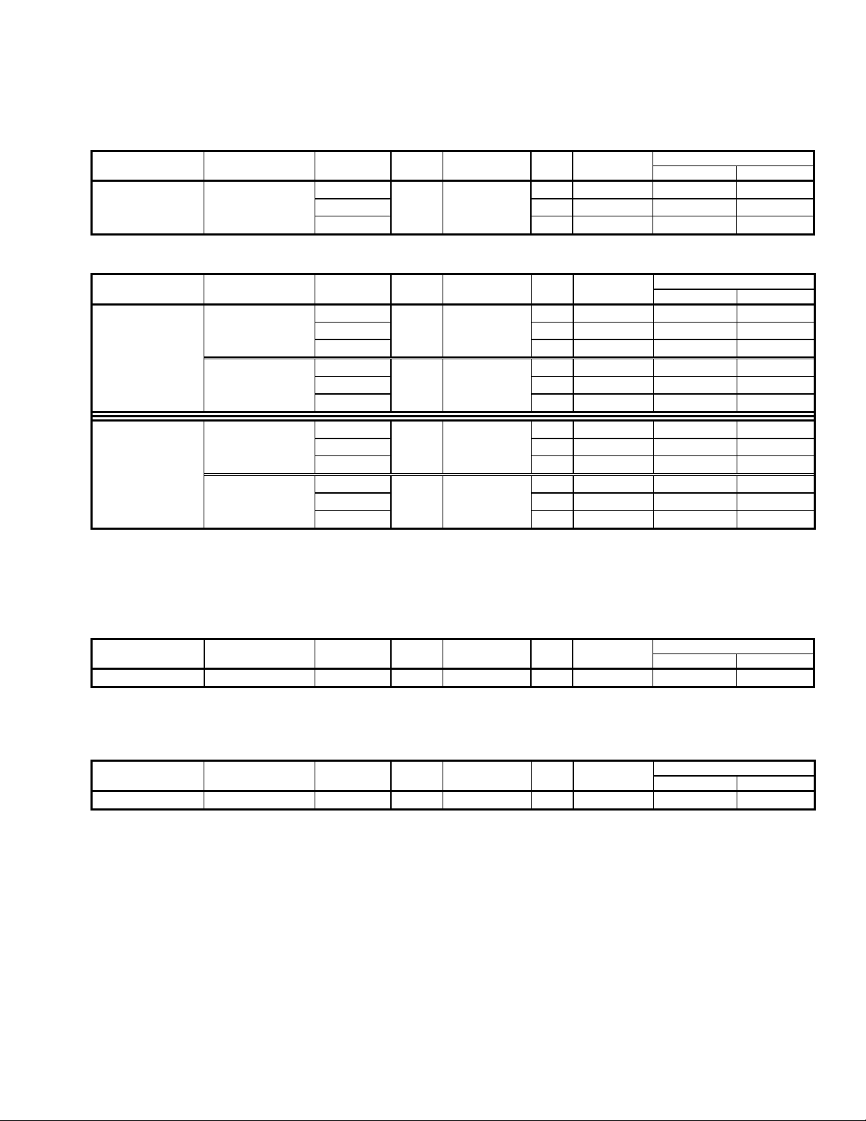
Electrical Configuration and Brewing Efficiency
US & Canada
CBS-2051
Electrical Heater Voltage Maximum Batches per Hour* (max 11) Config. Code Configuration (AC) Phase Wires KW Amp draw Cold Water Hot Water
E51016 2 X 3 KW 120/208 4.6 22.1 7.7 11.0
CBS-2052
Electrical Heater Voltage Maximum Batches per Hour* (max 22) Config. Code Configuration (AC) Phase Wires KW Amp draw Cold Water Hot Water
E52016 Option 1 120/208 4.6 22.4 7.7 18.6
Universal 2 X 3 KW 120/220 single 3 + ground 5.1 23.7 8.9 21.6
Wiring
Total 3 X 3 KW
Heaters 3 X 3 KW 120/220 three 4 + ground 7.7 20.6 13.4 22.0
E52026 Option 1 120/208 7.6 36.9 12.8 22.0
Universal 2 X 5 KW 120/220 single 3 + ground 8.5 39.0 14.9 22.0
Wiring
Total 3 X 5 KW
Heaters 3 X 5 KW 120/220 three 4 + ground 12.7 33.9 22.0 22.0
1.5 gallons per batch
120/220 single 3 + ground 5.1 23.4 8.9 11.0
1.5 gallons per batch
(Factory Setting)
(Factory Setting)
* Based on standard factory settings: 4.0 minute brew time; 0% prewet, 0% bypass; 200 F water.
Option 2 120/208 6.9 19.5 11.5 22.0
120/240 9.1 22.5 15.4 22.0
Option 2 120/208 11.4 32.0 19.2 22.0
120/240 6.1 25.5 10.3 11.0
120/240 6.1 25.8 10.3 22.0
120/240 10.1 42.5 17.1 22.0
120/240 15.1 36.9 22.0 22.0
Export
CBS-2051
Electrical Heater Voltage Maximum Batches per Hour* (max 11) Config. Code Configuration (AC) Phase Wires KW Amp draw Cold Water Hot Water
E51026 2 X 3 KW 220 single 2 + ground 5.1 23.4 8.9 11.0
♦ Not available at time of publication.
CBS-2052
Electrical Heater Voltage Maximum Batches per Hour* (max 22) Config. Code Configuration (AC) Phase Wires KW Amp draw Cold Water Hot Water
E52036 2 X 3 KW 120/220 single 3 + ground 5.1 23.7 8.9 21.6
1.5 gallons per batch
1.5 gallons per batch
* Based on standard factory settings: 4.0 minute brew time; 0% prewet, 0% bypass; 200 F water.
3
Page 4
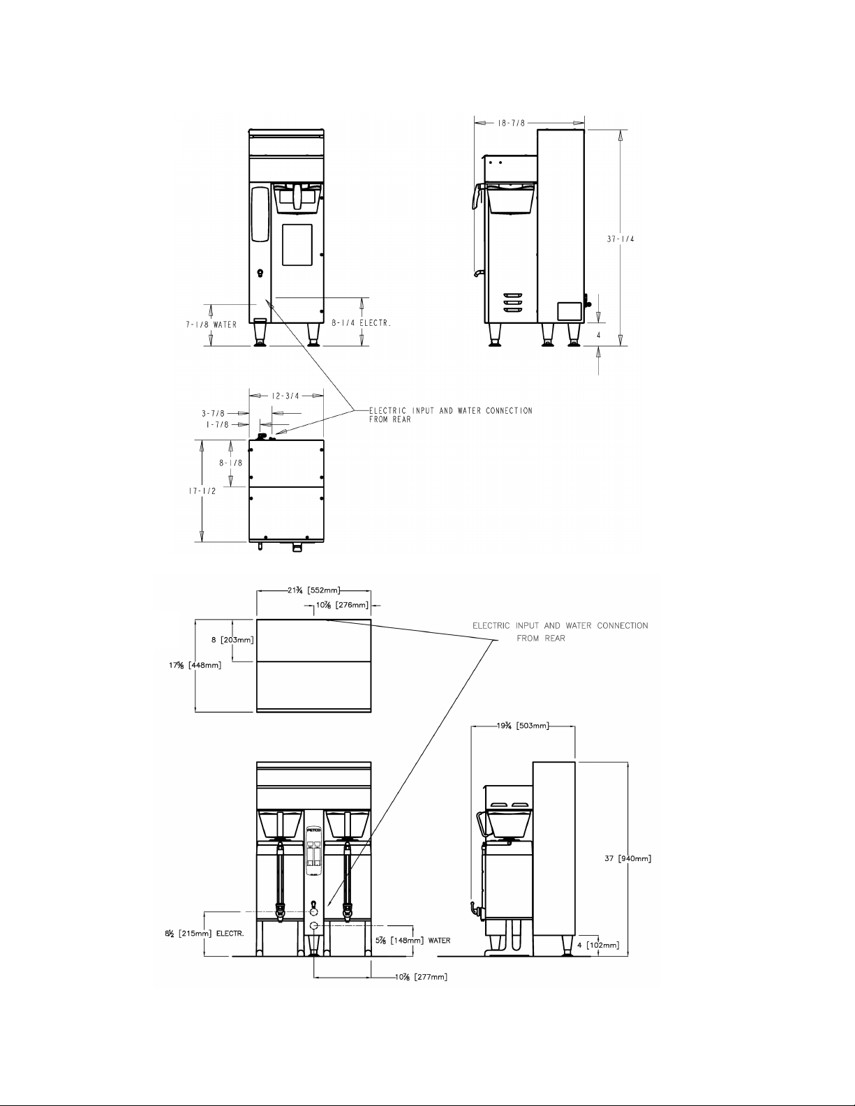
CBS-2051
Dimensions & Utility Connections
CBS-2052
4
Page 5

Installation
(For Qualified Service Technicians Only)
Keys To A Successful Installation
If not installed correctly by qualified personnel, the brewer may not operate properly and damage may result.
Damages resulting from improper installation are not covered by the warranty.
Here are the key points to consider before installation:
Electrical:
All FETCO brewers require NEUTRAL. Ground is not an acceptable substitute. Installation without neutral
may cause damage to the electronic components.
Universal wiring: This brewer can be configured for single or three phase operation. Conversion
instructions are described later in this section.
The electrical diagram and universal wiring instructions are located on the inside of the lower cover.
The installation must comply with applicable federal, state, and local codes having jurisdiction at your
location. Check with your local inspectors to determine what codes will apply.
Plumbing:
This equipment is to be installed to comply with the applicable federal, state, or local plumbing codes.
The water line must be flushed thoroughly prior to connecting it to the brewer to prevent debris from
contaminating the machine.
Verify that the water line will provide at least 1 gallon per minute for the CBS-2051, and 1.5 gallons per
minute for the CBS-2052 before connecting it to the brewer.
General:
Utilize only qualified beverage equipment service technicians for installation. A Service Company Directory
may be found on our web site, http://www.fetco.com.
Installation Instructions
Brewer Setup
1. Review the Dimensions for the unit you are installing. Verify that the brewer will fit in the space intended for it,
and that the counter or table will support the total weight of the brewer and dispensers when filled.
2. The brewer’s legs are shipped inside the brew baskets.
Remove the brew basket(s) and the coffee dispenser(s).
Place the brewer on its back and screw in the legs.
3. Place the brewer on the counter or stand.
4. When the brewer is in position, level it front to back as well
as side to side by adjusting the legs.
5. Remove the lower cover to access the water and electrical connections. Knock-outs are provided in the back
and base of the brewer body for the connections.
Water Connection
1. Water inlet is a 3/8 inch male flare fitting.
2. The brewer can be connected to a cold or hot water line. Cold water is preferred for best coffee flavor, but hot
water will allow for faster recovery times.
3. Install a water shut off valve near the brewer to facilitate service. If an in-line water filter is used, it should be
installed after the water shut off valve and in a position to facilitate filter replacement.
4. Flush the water supply line and filter before connecting it to the brewer.
5. Verify that the water line will provide at least 1 gallon per minute for the CBS-2051, and 1.5 gallons per minute
for the CBS-2052, and that the water pressure is between 20 and 75 psig.
6. Use a wrench on the factory fitting when connecting the incoming water line. This will reduce stress on the
internal connections and reduce the possibility of leaks developing after the install has been completed.
le vel ing the brewer only. Do not use
f or height adjustment or extend them
higher than necessary.
Warning: Legs are to be adjusted for
5
Page 6
Electrical Connection
1. Verify that the actual voltage at the electrical service connection is compatible with the specifications on the
brewer’s serial number label. Make sure the electrical service includes neutral.
2. The temperature and water tank fill level are pre-set at the factory. There is no need to turn off the heaters
during the installation process. The heaters are disabled by the control board until the tank is full of water. The
heating process will start automatically when the tank has filled.
3. A terminal block is provided for connecting the incoming power wires. Consult local codes to determine if a
cord and plug can be installed, or if the unit must be hard wired.
4. A fused disconnect switch or circuit breaker on the incoming power line must be conveniently located near the
brewer, and its location and markings known to the operators.
5. The body of the brewer must be grounded to a suitable building ground.
A ground lug is provided in the brewer next to the power terminal block.
Use only 10 gauge copper wire for grounding.
6. Electrical connections must be secured in-place within the unit to meet
electrical shock, this
unit must be properly
gro un ded.
national and local standards.
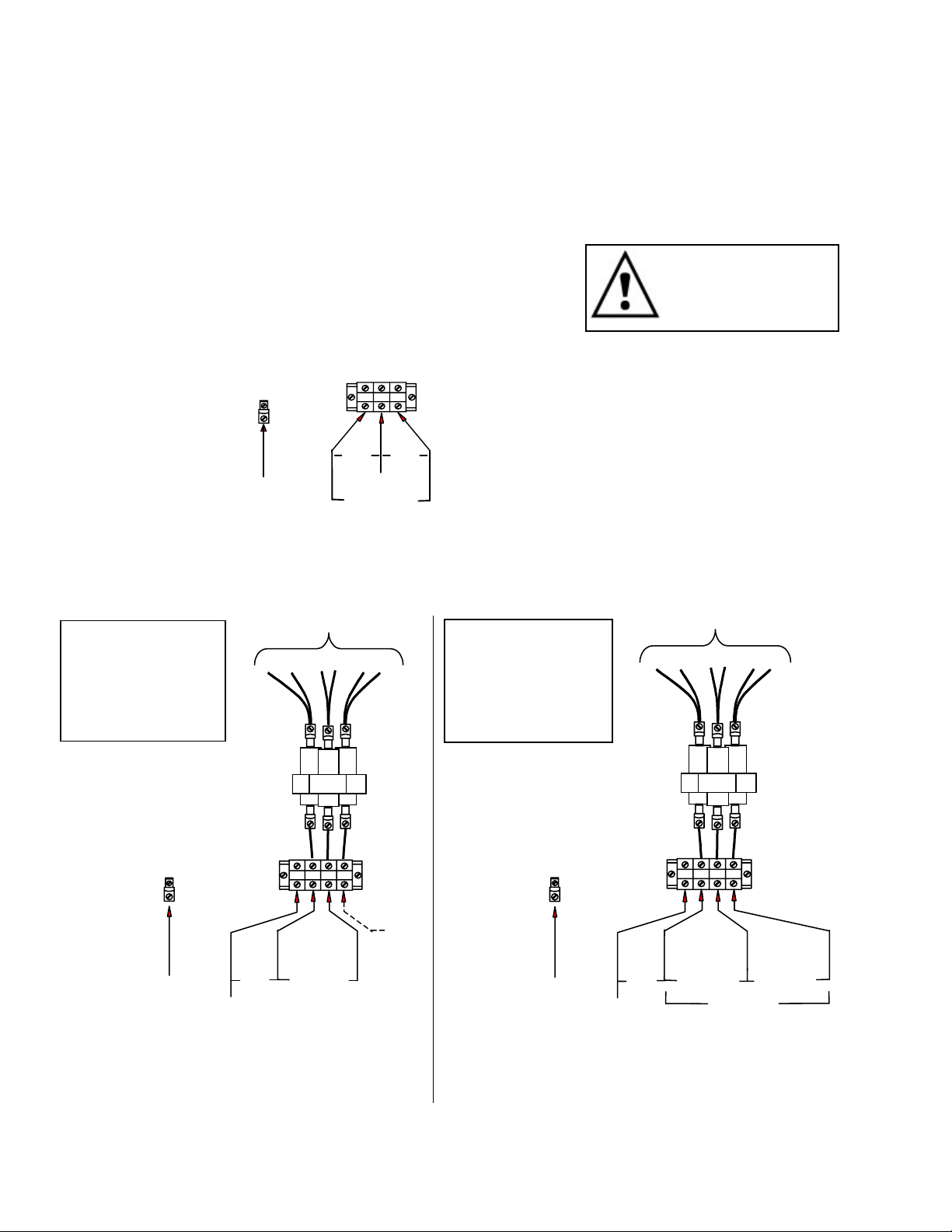
7. Connect the incoming power wires to the terminal block in accordance with applicable codes.
CBS-2051
GROUND LUG
L1
N
L2
120V 120V
Warning : To pr event
N
208-240V
GROUND
WIRE
8. The CBS-2052 is shipped from the factory configured for either single phase or three phase operation,
depending on the version that was ordered. A tag attached to the terminal block will indicate which way the
unit was configured. To change the configuration, change the relay and heater wires as shown below. Make
sure that all connections are tight. These instructions are also located on the inside of the lower cover.
CBS-2052
SINGLE PHASE
CONFIGURATION
120/208-240 VAC
3 wires + ground
GROUND
LUG
HEATER WIRES
4 & 6
1 & 5
2 & 3
CBS-2052
THREE PHASE
CONFIGURATION
120/208-240 VAC
4 wires + ground
H1
H2 H3
RELAY
L3
L1
N
L2
NOT
USED
GROUND
LUG
HEATER WIRES
1 & 2 3 & 4
H1
H2 H3
RELAY
L1
L2
N
5 & 6
L3
GROUND
WIRE
120V
N
208-240V
120V
WIRE
N
GROUND
208-240V 208-240V
208-240V
Terminal block: Connect incoming wires to L1, L2, N, Ground
Relay terminal: H1 - Connect heater wires 1 & 5
H2 - Connect heater wires 4 & 6
H3 - Connect heater wires 2 & 3
Terminal Block: Connect incoming wires to L1, L2, L3, N, Grnd.
Relay terminal: H1 - Connect heater wires 1 & 2
H2 - Connect heater wires 3 & 4
H3 - Connect heater wires 5 & 6
6
Page 7
Final Setup
1. Turn on the incoming water supply line and inspect both inside
and outside of the brewer for leaks in all fittings and tubes
2. Turn on the incoming power.
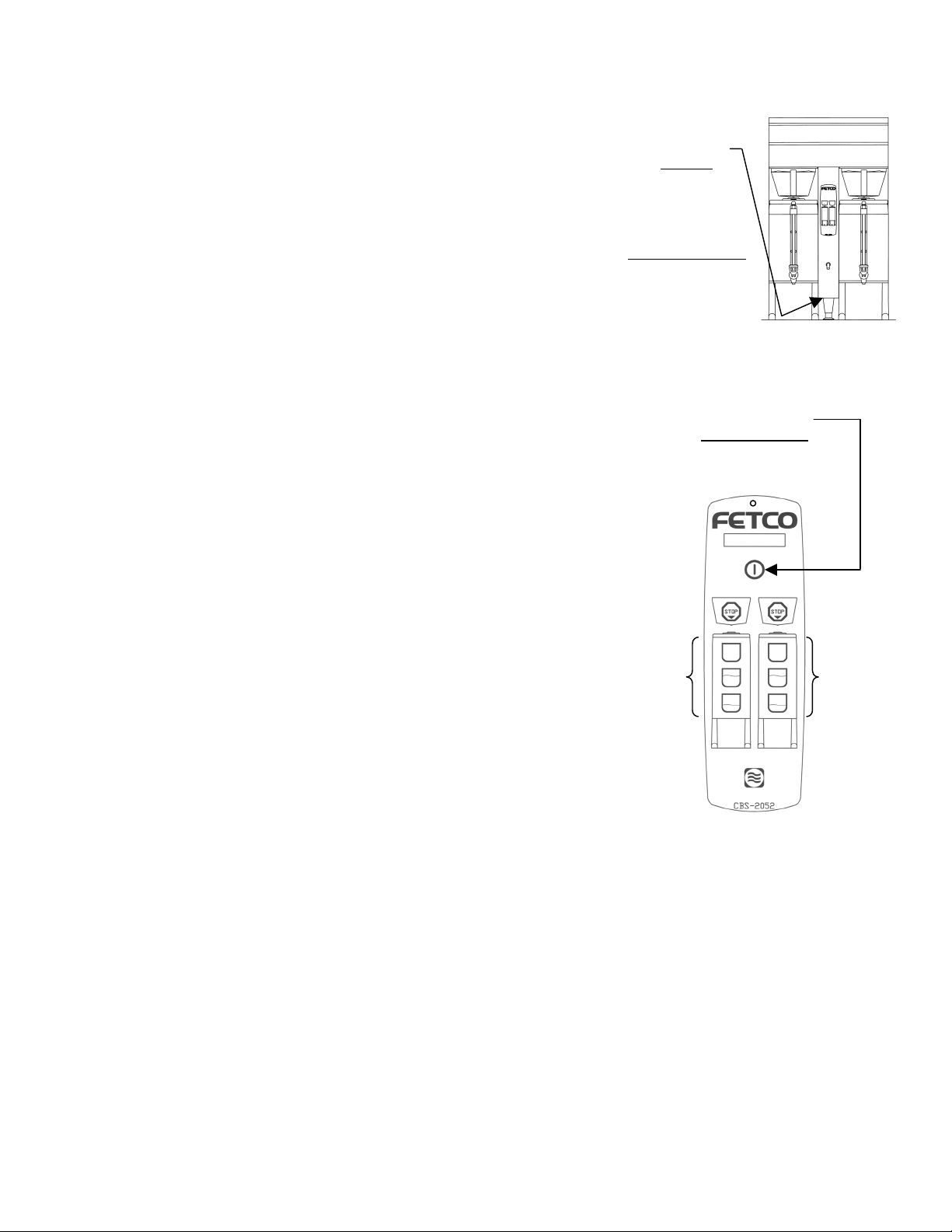
3. Press the brewer’s main power switch, which is hidden behind the
front leg of the brewer. The control panel on/off switch will begin
flashing. Press this switch.
4. Within 6 seconds, the hot water tank will begin filling until the
water is sensed by the probe at the top of the tank. The display will
read “FILL”. The heaters will be disabled by the control board until
the tank is full.
5. While the water is heating, the display will read “LO”. Once the
temperature has reached 175°F, the actual water temperature will
also be displayed. After the water has reached the set
temperature, the display will be blank. There is no “ready” light.
6. Review the Operating Instructions. Brew one full batch (water
only) on each side to confirm proper fill levels. The brewer is
factory set with water only (no coffee) to dispense the correct
amount of water. If the actual volume is slightly different from the
programmed volume, fine tuning the brewer may be necessary.
See #60 – 63 in the Advanced Settings & Diagnostics section.
7. Re-attach the covers after one final inspection for leaks. Look
closely in the top of the brewer at the dispense fittings during this
inspection.
Operator Training
Review the operating procedures with whoever will be using the
brewer. Pay particular attention to the following areas:
1. Always pre-heat the dispensers before the first use of each day by
filling them half way with hot water, and letting them stand for at
least 15 minutes.
2. Don't remove the brew basket until it has stopped dripping.
3. Make sure the dispenser is empty before brewing into it.
4. Show how to attach covers, close, and or secure the thermal
dispensers for transporting.
5. Show the location and operation of the water shut off valve as well
as the circuit breaker for the brewer.
6. Steam from the tank will form condensation in the vent tubes. This
condensation will drip into and then out of the brew baskets. 1/4
cup discharging overnight is possible. Place an appropriate
container under each brew basket when not in use.
7. We recommend leaving the power to the brewer on overnight. The
water tank is well insulated and will use very little electricity to
keep the tank hot. Leaving the brewer in the on position will also
avoid delays at the beginning of shifts for the brewer to reach
operating temperature.
MAIN POWER
SWITCH
LOCATED UNDER
FRONT PANEL,
DIRECTLY BEHIND
FRONT LEG.
CIRCUIT BREAKER
LOCATED BEHIND
MAIN POWER
SWITCH.
FLASHING = MAIN POWER ON
LIT = CONTROL PANEL ON
BREW
SWITCHES
CONTROL PANEL
ON/OFF SWITCH
OFF = NO POWER
7
Page 8
Operating Instructions
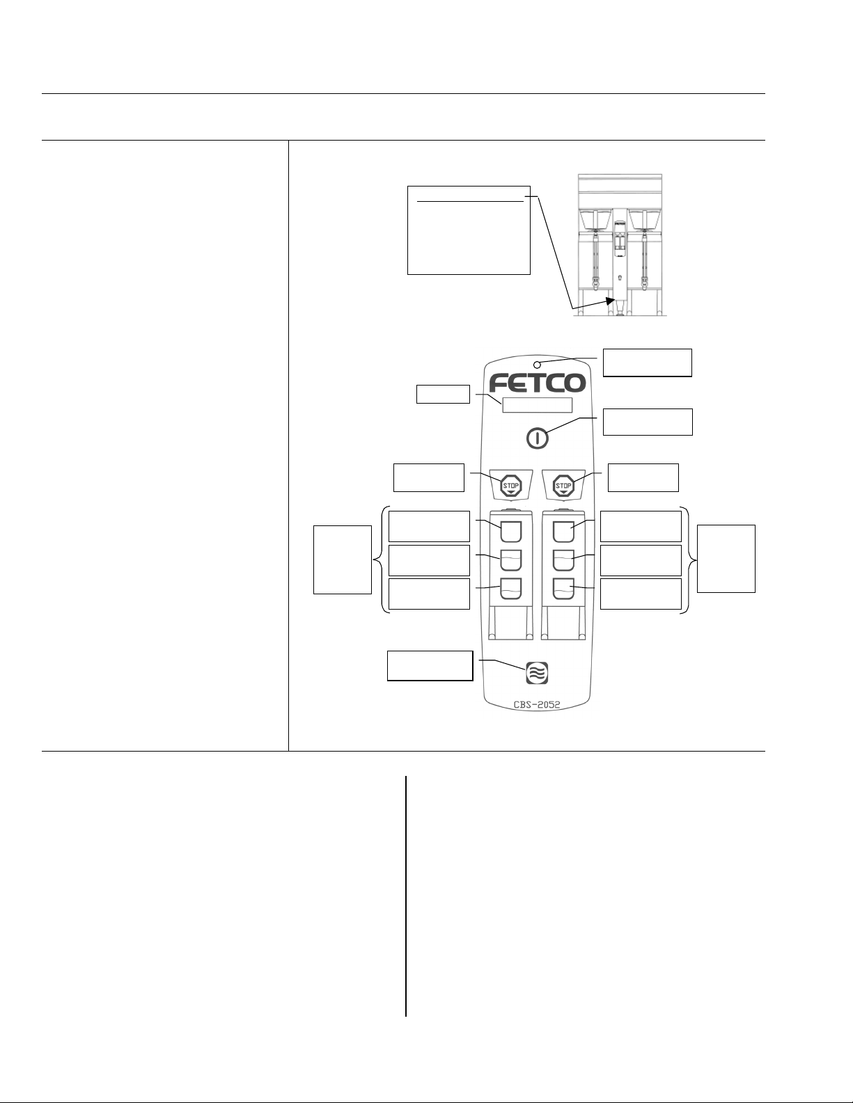
Control Panel Functions
Only switches that are active are illuminated.
Switches that are inactive or disabled are invisible.
Main Power Switch
X
Controls all power to brewer
Indicator lamp at top of panel.
Control Panel On/Off Switch
Y
Secondary power switch. Does not
disconnect main power.
Flashing = Off
Lit = On
Invisible = Main Power Off
Display
Z
”FILL” = Water tank is filling.
”LO XXX” = Unit is heating, not
ready to brew. (XXX = actual
temperature, if over 175°F)
”NO BAS” = Brew basket not in
position.
Blank = Ready to brew.
Also displays error messages.
Stop Switches
[
Stops brew cycle
Lit = Brew cycle in progress
Invisible = Not brewing, or dripping
in progress
Brew Switches
\
Starts brew cycle
Must be held in for 1 second
Flashing = Brew cycle in progress
Lit = Ready to brew
Invisible – Not ready to brew, or
batch disabled
(See Programming Section)
Hot Water Switch
]
Dispenses hot water from faucet
Hold in to dispense
Brewing
1. Turn the main power switch and control
panel switch on.
2. Prepare a brew basket with the correct size
filter and appropriate amount of coffee.
3. Slide the brew basket completely into the
rails.
4. Place a clean, empty, preheated dispenser
under the brew basket.
5. Select a batch from the available choices,
and hold the corresponding BREW button in
for 1 second to start the brew cycle.
6. The STOP button will illuminate, and the
selected BREW button will flash, indicating
that brewing is in progress. All other BREW
buttons will extinguish.
TO STA RT
PRESS
AND
HOLD
FOR 1
SECOND
\
[
]
X
MAIN POWER SWITC H
DIRECTLY BEHIND
Z
STOP
BREW CYCLE
BREW- LARGE
PORTION
BREW - MEDI UM
PORTION
BREW - SMA LL
PORTION
HOT WA TER
SWITCH
LOC A T E D U N DE R
FRONT PANEL,
FRONT LEG.
DISPLAY
MAIN POWER
INDICATOR LAMP
CO NTRO L PANE L
ON/OFF SWITCH
STOP
BREW CYCLE
BREW- LARGE
PORTION
BREW - MEDI UM
PORTION
BREW - SMA LL
PORTION
7. When the brew cycle is finished, the STOP
button will extinguish and the BREW button will
continue flashing, indicating that coffee may still
be dripping from the bottom of the brew basket.
8. Before removing the brew basket or dispenser,
visually verify that dripping has stopped.
Notes:
Preheat dispenser by filling at least ½ full with
water at brewing temperature. Allow it to sit for
at least 15 minutes before draining.
A sensor will prevent the brewer from operating
if the brew basket is not all the way in.
A brew basket lock will prevent removal of the
brew basket during brewing and dripping
[
Y
\
PRESS
AND
HOLD
FOR 1
SECOND
TO STA RT
8
Page 9

g
Batch Settings
Turn the brewer off by pressing the main power switch.
Press the main power switch again to turn the unit on.
Quickly hold the STOP button for 3 seconds. P r G
The display will show the software version for 3 seconds. Example:
Batches are numbered 1 – 3 (CBS-2051) or 1 – 6 (CBS-2052)
BATCH #
Example:
Next, the first batch parameter is displayed – batch 1, brew volume
Use the SCROLL UP and SCROLL DOWN buttons to adjust.
Press the STOP button to go to the next parameter – brew time. 1.2 4.00
Continue this way until all parameters are programmed for batch #1.
(See the chart below for an explanation of each parameter.)
Next, batch #2 programming begins.
Batches 2, 3, 5, and 6 may be disabled by leaving them set to “OFF”.
Change to “ON” to enable. Batches 1 and 4 cannot be disabled.
After all batches are programmed, go to temperature settings.
Left Side – Lar
Programming
PARAMETER
SETTING
1.1 1.50
e Batch – Brew Volume 1.5 Gal.
(See next page)
Display
S t b y
0.0 1.35
1.1 1.50
2.0 OFF
7 200
MAIN POWER
ADVANCE
TO NEXT
PARAMETER
SCROLL
DOWN
SAVE
CHANGES
AND EXIT
SWITCH IS
BEHIND
FRONT LEG.
Important! After programming, you must press the HOT WATER button to save the settings and exit
programming mode, or changes will be lost. You may exit programming at any time.
Batch Parameters
X=Batch Number (1 - 6)
Parameter Name Range Increment Default Setting Comment
X.0 Batch Enabled or
Disabled
X.1 Brew Volume
(Gallons)
X.2 Brew Time (Min:Sec) 2:00 – 24:00 0:30 4:00 minutes
X.3 Bypass Percent 0.00 – 40.0% 1% 0 % Percentage of total
X.4 Prewet Percent 0.00 – 15.0% 1% 0 % Percentage of total
X.5 Prewet Delay
(Min:Sec)
X.6 Drip Delay (Min:Sec) 0:30 – 6:00
On/Off Batch 1 & 4 = ON
Batch 2, 3, 5, 6 = OFF
Batch 1 & 4 cannot
be disabled.
0.25 – 3.00 0.01 1.5 gallons To display liters, see
# 59 in Advanced
Settings section.
brew volume
brew volume
0:10 – 5:00 0:10 1:00 minute The time between
prewetting and start
of brew cycle.
0:10 1:30 minute The time between
Minutes
end of brew cycle
and unlocking of
brew basket.
9
Page 10

Temperature Settings
Parameter Name Range Default Setting Comment
7
Water Temp. (°F) 180°F - 208°F 200°F
Inside tank. Will be slightly lower at
spray head. To display in ° Celsius,
see # 58 in Advanced Settings.
8 Hot Water Service A (auto) / On / Off A (auto) A= Faucet will dispense only when not
brewing.
On=Faucet always enabled.
Off=Faucet always disabled.
9 Brew at Set
Temperature
0 - 1 1 0=Will brew at any temperature.
1=Will brew only at set temperature.
Note: Changes will not take effect until
Parameter Name Range Default Setting Comment
10 Enter Advanced
0 - 1 0 0 = Skip Advanced Settings &
Settings &
Diagnostics
the next brew cycle is completed.
Diagnostics. Loop back to start of
batch programming cycle.
1 = Enter Advanced Settings &
Diagnostics.
Important! To save your changes, press to exit programming mode and return to operating mode.
Advanced Settings and Diagnostics
Address Description Range Default Comment
50 Water Level
in Tank
51 Water Resistance Water resistance (ohms) as read by probe.
52 Brew Basket
Sensor State
(left / right)
53 Power Relay State 0 - 1 Checks power relay on control board. To test,
54 N/A Not used on this model.
55 Tank Temperature
56 Circuit Board
Configuration
57 Reload Defaults 0 - 1 0 Changes all settings to default factory settings.
58 Temperature Scale F or C F F = Displays temp in degrees Fahrenheit
59 Water Volume
Scale
0 - 1 Tests if water is touching probe.
0 = Tank is less than full
1 = Tank is full
0 - 1 To test, slide the brew basket in and out. Display
should toggle between 0 and 1.
0 = Brew basket in. 1 = Brew Basket out.
press Control Panel Power Switch.
Display should toggle between 0 and 1.
0 = Power relay OFF, switch should blink.
1 = Power relay ON, switch should be lit..
180°F - 208°F
Displays current tank temperature. If temperature
is below 175°F, displays “LO”.
Should read 110 for CBS-2051
111 for CBS-2052
0 = Do not reload defaults
1 = Reload all default settings
If 1 is selected, you must advance to the next
address for this change to take effect.
C = Displays temp in degrees Celsius
GAL or LTR GAL GAL = Displays volume in gallons
LTR = Displays volume in liters
10
Page 11

Address Description Range Default Comment
60
and
61
62
and
63
Left Brew Valve
Flow Rate
Right Brew Valve
Flow Rate
Left Bypass Valve
Flow Rate
Right Bypass
Valve Flow Rate
0.49 – 1.49
If #59 is GAL
or
1.85 – 5.64
If #59 is LTR
0.28 – 0.38
If #59 is GAL
or
1.05 – 1.44
If #59 is LTR
0.92
3.48
0.33
1.24
Use this to compensate for minor discrepancies in
actual volume versus programmed volume. Set
lower to increase volume, higher to decrease
volume. The following formula can be used to
determine the correct setting:
ACTUAL VOLUME
PROGRAMMED VOLUME
X
CURRENT
SETTING
=
64 Keypad Test 0 - 1 0 Tests function of control panel switches.
0 - Skip keypad test
1 - Keypad test active
Starting at the top, press each button. Display will
read the name of the switch being pressed.
Brew switches are named S1, S2, S3, etc.
The hot water switch must be pressed last, as this
will exit the test.
65 Relay Test 0 - 1 0 0 - Skip relay test. Loop back to #50
1 – Relay test active. Go to #90
Press to save the settings and exit Diagnostic mode.
Press again to exit Programming mode and return to Operating mode.
Relay Test
Tests the individual relays which control various components.
Use either batch button to actuate the relays.
tes ts, hot water may
be d ispensed from
the valve being tested.
Warning: During these
To begin, you must first press the blinking Control Panel Power Switch.
Address Description Comment
90 Left or Single Brew Valve
91 Right Brew Valve
92 Left or Single Bypass Valve
93 Right Bypass Valve
94 Hot Water Faucet
95 Fill Valve
96 Heater To protect the heaters, this test will work only if the tank is full.
97 Left or Single Brew Basket Lock
98 Right Brew Basket Lock
Press to exit Relay Test.
Press again to exit Diagnostic mode.
Press again to exit Programming mode and return to Operating mode.
NEW
SETTING
11
Page 12

Error Codes
How to Clear Error Codes
Code Description Possible Cause Corrective Action
001 Internal Error
System had to
reload default
settings.
Control board
failure.
Clear error.
Re-program the
brewer to the desired
specifications. If error
occurs again, replace
control board.
002 Power Failure
Power state does
Relay on control
board has failed.
Replace control
board.
not match feedback
loop state.
050 Shorted
Probe failure. Replace probe. Enter
temperature probe.
051 Open temperature
probe.
Bad probe
connection, or
probe failure.
Check all
connections.
Replace probe if
necessary.
075 Brew basket lock or
sensor failure.
Basket was in place
Brew basket lock
has failed or sensor
needs adjustment.
Repair or replace
brew basket lock, or
adjust sensor.
when brew cycle
started, but was
pulled out during the
brew cycle. If this
error occurs, the
brew basket lock
has failed, or the
sensor is out of
adjustment.
100 Initial Fill Error
Initial fill time was
more than 8.6
minutes.
Water supply flow
rate is too low.
Watch for short
potting during brew
cycle. Investigate
cause of low flow
rate. (Clogged water
filter, etc.)
101 Error on refill
Tank did not refill
within 2 minutes.
Water supply flow
rate is too low.
Watch for short
potting during brew
cycle. Investigate
cause of low flow
rate. (Clogged water
filter, etc.)
102 Unwanted Fill
When brewer is idle,
the fill valve was
activated for more
than 30 seconds
during a 1 hour
period.
Possible leak in
tank, fitting, or
valve.
Output on control
board has failed,
causing a dispense
valve to open.
Check inside of
machine for leaks.
Replace control
board.
Software Ver. 1.51
and lower
Enter
programming
mode, then exit
programming
mode.
Enter
programming
mode, then exit
programming
mode.
programming
mode, then exit
programming
mode.
Enter
programming
mode, then exit
programming
mode.
Press the
flashing control
panel power
switch to resume
operation.
Press the control
panel power
switch.
Error message is
cleared
automatically at
end of brew
cycle.
Enter
programming
mode, then exit
programming
mode.
Software Ver. 2.0
and higher
Turn main power
switch off and
on.
Turn main power
switch off and
on.
Turn main power
switch off and
on.
Turn main power
switch off and
on.
Press the
flashing control
panel power
switch to resume
operation.
Press the control
panel power
switch.
Error message is
cleared
automatically at
end of brew
cycle.
Turn main power
switch off and
on.
12
Page 13

200 Flat Line
Temperature
(Water is boiling)
System is calling for
heat, but the
temperature does
not rise at least 2°F
within 5 minutes.
201 Heater Open
System is calling for
heat, but the
temperature does
not rise at least 2°F
within 10 minutes.
This error is
disabled during
brewing and while
using the hot water
faucet.
202 Heater Short
System is not calling
for heat, but
temperature rises
more than 5°F.
255 Keypad Error
A switch was
pressed for more
than 45 seconds.
Mercury relay is
stuck closed, bad
output on control
board, or
temperature is set
too high for altitude.
Heating element
failure.
Possible mercury
relay stuck closed,
or bad output on
control board.
Switch was held in
too long, or switch
is stuck closed.
Check mercury relay,
check control board
output, or adjust
temperature for
altitude.
Check and replace
heating elements if
necessary.
Check mercury relay
and control board.
Clear error and try
again. If error occurs
without switch being
pressed, replace
input board.
Enter
programming
mode, then exit
programming
mode.
Enter
programming
mode, then exit
programming
mode.
Enter
programming
mode, then exit
programming
mode.
Enter
programming
mode, then exit
programming
mode.
Turn main power
switch off and
on.
Turn main power
switch off and
on.
Enter
programming
mode, then exit
programming
mode.
Turn main power
switch off and
on.
Service
Utilize only qualified beverage equipment service technicians for service. A Service Company Directory may be
found on our web site, http://www.fetco.com. Companies listed as “Extractor Authorized” stock parts for these
models.
When changing the control board, check the software version on the chip. Example- V1.40. If the chip on the
replacement board has an older software version than the board being replaced, carefully remove the chip from the
old board and place it in the new board. Use a chip puller if one is available.
Cleaning & Maintenance
Brewer: The spray plates should be removed and cleaned periodically to remove hard water deposits. In areas
with extremely hard water, it may be necessary to do this weekly. Monthly cleaning may be sufficient in areas with
average water conditions.
LUXUS Dispensers :
Use the same techniques and products as you would use to clean any coffee urn. I.E.,
a) the sight gauge brush to scrub the gauge
b) urn brush for inside the dispenser
c) urn cleaner to clean the dispenser
d) stainless steel polish for the outside
e) hot water and towels for the faucet parts
13
Page 14

Care of Stainless Steel
(These procedures were developed by NAFEM and Packer Engineering.)
1. Use the proper tools. Don’t use; steel pads, wire brush, or scrapers
When cleaning your stainless steel products, take care to use non-abrasive tools. Soft cloths and plastic
scouring pads will not harm the steels passive layer. Stainless steel pads can also be used but the
scrubbing motion must be in the direction of the manufacturers polishing marks. Step 2 tells you how to find
the polishing marks.
2. Clean with the polish lines.
Some stainless steels come with visible polishing lines or “grain.” When visible lines are present, you
should always scrub in a motion that is parallel to them.
When the grain cannot be seen, play it safe and use a soft cloth or plastic scouring pad.
3. Use alkaline, alkaline chlorinated or non-chloride containing cleaners.
While many traditional cleaners are loaded with chlorides, the industry is providing and ever increasing
choice of non-chloride cleaners. If you are not sure of your cleaner’s chloride content contact your cleaner
supplier. If they tell you that your present cleaner contains chlorides, ask if they have an alternative. They
probably will. Also, avoid cleaners containing quaternary salts as they also can attack stainless steel and
cause pitting and rusting.
4. Keep your equipment clean.
Use alkaline, alkaline chlorinated or non-chloride cleaners at recommended strength. Clean frequently to
avoid build-up of hard, stubborn stains.
5. Rinse, Rinse, Rinse.
If chlorinated cleaners are used you must rinse, rinse, rinse and wipe dry immediately. The sooner you
wipe off standing water, especially when it contains cleaning agents, the better. After wiping the equipment
down, allow it to air dry for the oxygen helps maintain the stainless steel's passivity film.
6. Never use hydrochloric acid (muriatic acid) on stainless steel.
7. Regularly restore / passivate stainless steel.
Recommended cleaners for specific situations.
Job Cleaning Agent Comments
Routine cleaning Soap, ammonia, detergent Medallion Apply with cloth or sponge
Fingerprints & Smears Arcal 20, Lac-O-Nu, Ecoshine Provides better film
Stubborn stains and discoloration Cameo, Talc, Zud, First Impression Rub in the direction of the polish lines
Grease and fatty acids, blood etc. Easy-off, De-Grease It, Oven Aid Excellent removal on all finishes
Grease and Oil Any good commercial detergent Apply with sponge
Restoration / Passivation Benefit, Super Sheen
Reference: Nickel Development Institute, Diversey Lever, Savin, Ecolab
14
Page 15

CBS-2052
Wiring Diagram
(CBS-2051 wiring diagram not availabel at time of publication)
15
Page 16

Parts – Brewer
CBS-2051
Main assembly and tank assembly drawings were not available at time of publication.
Spray housing assembly – see figure 3.
Brew basket assembly – see figure 4.
CBS-2051 Major Components:
PART NO DESCRIPTION
51023 CONTROL BOARD, 2000 SERIES
51026 INPUT BOARD, 2051
54022 TEMPERATURE PROBE ASSY, 8”
102134 WATER LEVEL PROBE ASSY., 2.6"
102135 REFERENCE PROBE ASSY.
57047 COIL ASSY REPAIR KIT, DSV-11, 120 VAC
57073 VALVE REBUILD KIT, DSV11
57042 COIL ASSY REPAIR KIT, DSV-10, 120 VAC
57072 VALVE REBUILD KIT, DSV10
57006 FILL VALVE ASSY., S-53, 120V
101160 BREW BASKET LOCK ASSY., 120V
101158 BREW BASKET SENSOR ASSY.
52060 RELAY
52061 TRANSFORMER, 120VAC/24VAC
52017 MERCURY RELAY, 120V, 30ADP
53061 THERMOSTAT, TEMP. LIMIT
53009 HEATING ELEMENT, 3 KW, 240V
16
Page 17

Figure 1 – CBS-2052
SEE
FIG. # 4
SEE
FIG. # 3
SEE FIG. # 2
Drawing for CBS-2051 was not available at time of publication.
17
Page 18

Parts List – Figure 1 – CBS-2052
ITEM QTY PART NO. DESCRIPTION
1 1 22037 CBS-2052 TANK INSULATION- BACK
2 1 22036 CBS-2052 TANK INSULATION-FRONT
3 1 102013 TANK COVER ASSY
4 1 24002 TANK COVER GASKET
5 1 102134 WATER LEVEL PROBE ASSY., 2.6"
6 (INCLUDED WITH #5)
7 1 104016 CBS-2052 TANK ASSEMBLY (SEE FIGURE 2)
8 2 25042 VENT SILICONE TUBE
9 1 32049 S.S. TUBE - HOT WATER OUTLET
10 1 31129 1/4 MPT X 3/8 COMPRESSION FITTING
11 1 102140 HOT WATER VALVE 120 VAC, VENTED
11 1 102153 HOT WATER VALVE 208/240 VAC, VENTED (EXPORT VERSIONS ONLY)
11 57047 COIL ASSY. REPAIR KIT, DSV-11, 120 VAC
(COIL, DIAPHRAGM, SPRING, & PLUNGER)
11 57073 VALVE REBUILD KIT, DSV11. (PLUNGER, SPRING, AND DIAPHRAGM)
12 8 83026 #8 INTERNAL TOOTH WASHER
13 34 84002 #8-32 S.S. NUT
14 1 22043 HOT WATER TUBE INSULATION
15 1 25043 3/8 I.D. X 5/8 O.D. X 4.25 SILICONE TUBE
16 1 32050 COLD WATER TUBE
17 1 57001 FILL VALVE ASSY.,S-45N, 120V, 1.5 GPM
17 1 57022 FILL VALVE ASSY.,S-45N, 220V, 1.5 GPM (EXPORT VERSIONS ONLY)
17 57004 FILL VALVE COIL, 120V (S-45N)
17 57021 FILL VALVE COIL, 220V (S-45N) (EXPORT VERSIONS ONLY)
17 57003 FILL VALVE REPAIR KIT (S-45N) (DIAPHRAGM, SPRING, & PLUNGER)
18 1 1445 TOP REAR COVER
19 11 82059 #8 X 32 3/8 T.H. S.S. SCREW
20 1 1446 TOP FRONT COVER
21 2 25044 3/8 I.D. X 5/8 O.D. X 7 1/2 BY-PASS SIL.TUBE
22 2 25045 .625 I.D X .965 O.D. 4.0'' BREW SILICONE TUBE
23 2 101160 BREW BASKET LOCK-ASSY, 120 V
23 2 101174 BREW BASKET LOCK-ASSY, 230 V (EXPORT VERSIONS ONLY)
24 2 101158 BREW BASKET SENSOR ASSY
25 1 57044 BY-PASS VALVE -LEFT 120 V
25 1 57077 BY-PASS VALVE- LEFT 208/240 V (EXPORT VERSIONS ONLY)
25 57047 COIL ASSY. REPAIR KIT, DSV-11, 120 VAC
(COIL, DIAPHRAGM, SPRING, & PLUNGER)
25 57073 VALVE REBUILD KIT, DSV11. (PLUNGER, SPRING, AND DIAPHRAGM)
26 2 --------- (SEE FIGURE 3) SPRAY HOUSING ASSY FOR 120V AND 220V
27 1 1030 CBS-2052 BODY WELDMENT
28 1 102116 CURTIS TERMINAL BLOCK NEUTRAL ASSY
29 4 86021 HEYCO SNAP BUSHING 1.375'' HOLE
30 1 54022 TEMPERATURE PROBE, 8", W/SLEEVE & COMP NUT
31 1 102135 REFERENCE PROBE ASSY.
32 2 84001 #6-32 NUT
33 1 53061 THERMOSTAT, TEMPERATURE LIMIT, 230 DEG. F
34 1 03233 LIMIT THERMOSTAT SPACER
35 1 45063 CBS-2052 OVERLAY
36 1 33007 S.S. DISP. FITTING LOCKNUT
37 1 02065 HOT WATER FAUCET TUBE WELDMENT
38 1 51023 CONTROL BOARD, 2000 SERIES TFC-T1685-010
18
Page 19

39 10 29007 #4 NYLON FINGERNUT
40 2 86032 HEYCO SNAP BUSHING 1.00'' HOLE
42 1 51027 INPUT BOARD, CBS-2052
44 1 51028 RIBBON CABLE
46 1 86038 HEYCO HOSE CLAMP DIA. 0.671-0.812
47 1 25046 3/8 I.D. X 5/8 O.D. X 15'' DRAIN SILICONE TUBE
48 4 86038 HEYCO HOSE CLAMP DIA. 0.671-0.812
49 1 57043 BY-PASS VALVE RIGHT 120 V
49 1 57076 BY-PASS VALVE RIGHT 208/240 V (EXPORT VERSIONS ONLY)
49 57047 COIL ASSY. REPAIR KIT, DSV-11, 120 VAC
(COIL, DIAPHRAGM, SPRING, & PLUNGER)
49 57073 VALVE REBUILD KIT, DSV11. (PLUNGER, SPRING, AND DIAPHRAGM)
50 1 1447 CBS-2052 RIGHT PANEL
51 3 73011 LEG, 4" ADJUSTABLE
52 1 52025 RELAY, MERCURY, 60AMP TP, 120V COIL
52 1 52038 RELAY, MERCURY, 60AMP TP, 240V COIL, (EXPORT VERSIONS ONLY)
53 1 52027 CIRCUIT BREAKER 10 AMP
55 1 58054 PUSH BUTTON SWITCH
56 1 102104 TERMINAL BLOCK ASSY
57 1 3240 PUSH BUTTON AND CIRCUIT BREAKER BRACKET
58 1 52068 TRANSFORMER, PRIMARY 208/240 V, SEC 24 V (EXPORT ONLY)
58 1 52059 TRANSFORMER, PRIMARY 120 V, SEC. 24 VAC,
59 1 52060 RELAY G2R-1A-T-DC12
60 10 23101 .600 SQUARE LIGHT PIPE
61 10 23121 LIGHT PIPE HOLDER
62 1 65001 SLU-70 ILSCO COPPER LUG CONNECTOR
63 1 58068 POWER SWITCH INDIC. LAMP, 120 V, SEC. 24V
63 1 58071 POWER SWITCH INDIC. LAMP, 208/240V, SEC. 24V (EXPORT ONLY)
64 2 25060 BY-PASS SILICON TUBE .625 X .375 X 1.5''
65 2 25061 BY-PASS SILICON TUBE INSERT .500 X .250 X .500''
66 2 86039 HEYCO HOSE CLAMP DIA. 1.031-1.188
67 2 86036 HEYCO HOSE CLAMP DIA. .875-1.00
68 2 86038 HEYCO HOSE CLAMP DIA. .671-.812
69 1 29011 POLYETHYLENE FLEXIBLE SPLIT CONDUIT 0.625" I.D.
70 1 46027 HOT WATER WARNING LABEL
71 2 83051 FLAT WASHER
72 2 101165 BREW BASKET ASSY. (SEE FIGURE 4)
73 2 46011 BREW BASKET WARNING LABEL
74 2 46028 INSTRUCTION LABEL
75 1 46029 MAIN POWER SWITCH LABEL
76 1 44019 SINGLE PHASE CONFIGURATION LABEL
76 1 44020 THREE PHASE CONFIGURATION LABEL
For current parts pricing, visit www.fetco.com.
19
Page 20

Figure 2 – Tank Assembly – CBS-2052
ITEM QTY PART NO. DESCRIPTION
1 2 31129 3/8'' X 1/4'' MPT CONNECTOR
2 3 31117 1/4'' LOCKNUT
3 2 31116 1/8'' LOCKNUT
4 2 31005 1/4'' HOSE X 1/8''MPT 90 DEG HOSE BARB ELBOW
5 2 31151 1/2'' LOCKNUT
6 2 31118 3/8'' LOCKNUT
7 2 83043 FLAT WASHER I.D. .688 X O.D. 1.125
8 2 31077 3/8'' BARB X 3/8'' MPT
9 2 83048 .835 I.D. X 1.25 O.D. FLAT WASHER
10 2 31150 HOSE BARB X MALE PIPE THREAD RIGID 5/8 X 1/2
11 3 84007 3/4-16 X 1/4'' S.S NUT
12 3 31021 3/4-16 X 1/4 FSPT HEX HEAD BUSHING
13 2 31027 3/8 COMPR. X 1/4 MPT MALE ELBOW
14 1 31082 3/8'' MPT X 1/4 MPT HEX NIPPLE
15 1 34004 BALL VALVE 3/8 X 3/8 MPT
16 1 31054 1/2'' HOSE BARB X 3/8 MPT
17 1 31036 1/4'' COMPR. X 1/4'' MPT CONNECT.
18 3 53056 HEATER ELEMENT ASSY, 5000 W 240VAC
18 3 53009 HEATER ELEMENT ASSY, 3000 W 240VAC
19 1 40023 TANK WELDMENT, CBS-2052
20
Page 21

Figure 3 – Spray Housing Assembly – CBS-2051 & CBS-2052
1
2
3
4
5
ITEM # QTY PART NO DESCRIPTION
1 4 82112 #8 X 3/4'' PAN HD. PHIL. T.S. 18-8 S.S. SCREW
2 1 57042 COIL ASSY. REPAIR KIT, DSV-10, 120 VAC
2 1 57075 COIL ASSY. REPAIR KIT, DSV-10, 240 VAC (EXPORT VERSION ONLY)
3 1 57072 VALVE REBUILD KIT, DSV10
4 1 102113 SPRAY HOUSING ASSY.
5 1 24035 O-RING, 5.5 I.D. X 5 11/16 O.D. X 3/32
6 1 102108 SPRAY PLATE ASSY., 5 7/8" DIA.
For current parts pricing, visit www.fetco.com.
6
21
Page 22

Figure 4 – Brew Basket Assembly, 16” X 6”, Part # 101165
1
ITEM QTY PART # DESCRIPTION
1 1 82096 HANDLE SCREW
2 1 23117 BREW BASKET HANDLE
2
3 1 9006 WIRE INSERT, 16 X 6
NOT
SHOWN
3
For current parts pricing, visit www.fetco.com.
F001 PAPER FILTERS, 15” X 5.5”
500 PER CASE
22
Page 23

Parts - LUXUS Dispensers
LUXUS LS & LD Series
Item Part No. Description
1-all sizes 102068 handle assembly
2-all sizes 102067 plug-knob assy. only
3- for LD 10 21044 sight gauge tube, 1 gal.
3- for LD 15 21045 sight gauge tube, 1.5 gal.
3- for LD 20 21046 sight gauge tube, 2 gal.
4- all sizes 83012 sight gauge washer, lower
5- all sizes 83013 sight gauge washer, upper
6- all sizes 71047 sight gauge cap
7- all sizes 71054 faucet upper assembly
8-all sizes 71035 faucet seat cup
9- for LD 10 102069 funnel assembly-1 gal ld
4- all sizes 83012 sight gauge washer, lower
5- all sizes 83013 sight gauge washer, upper
6- all sizes 71047 sight gauge cap
7- all sizes 71054 faucet upper assembly
8-all sizes 71035 faucet seat cup
9- for LD 10 102069 funnel assembly-1 gal ld
9- for LD 15 102070 funnel assembly-1.5 gal ld
9- for LD 20 102071 funnel assembly-2 gal ld
10- all sizes 102066 base assembly,
11- all sizes 71056 faucet handle-black
11- all sizes 71055 faucet handle-orange
not shown 74003 sight tube brush 16"
LUXUS TPD-1.5
Item Part No. Description
1 71026 faucet, complete, black handle (ES)
1 71037 faucet upper assy. w/black handle
1 71035 faucet seat cup
1 71028 faucet handle- black
1 71027
2 31045 faucet union nut
3 71036 faucet "c" ring
4 102052 faucet shank assembly
5 24009 faucet shank "o" ring ½" x ¾"
6 12018 vent top plug
7 71017 sight gauge washer lower
8 71024 sight gauge cap
9 71018 sight gauge washer upper
6-9 102020 sight gauge cap and vent assy.
10 21033 sight gauge tube 10-5/16" (plastic)
10 71038 sight gauge tube 10-5/16" (glass)
11 82015 faucet shank screw-2 required
12 101038 twist lock cover assembly
13 101052 brew funnel assembly
14 23024 plastic bottom
15 41011 LUXUS label
For current parts pricing, visit www.fetco.com.
(includes 3 piece handle, plug-knob assy., screw
bushings and screws)
(includes handle, cap, spring and seat cup)
(includes handle, cap, spring and seat cup)
(includes base, foot, & 3 screws)
(handle, spring, seat cup and nut)
faucet handle, decaf faucet (orange)
23
Page 24

 Loading...