


CBS-2051E
FETCO®, LUXUS®, EXTRACTOR® and Driven To Pioneer Innovation™ are trademarks or trade names of Food Equipment Technologies Company.
© 2005 Food Equipment Technologies Company Part # P021 October 20, 2005
NOTICE TO INSTALLER: Please leave this book with the machine.
www.fetco.com
User’s Guide
Table of Contents
Contact Information ..................................................2
Description & Features .............................................2
Specifications............................................................2
Requirements........................................................2
Weights and Capacities ........................................2
Electrical Configuration and Brewing Efficiency ...3
Dimensions & Utility Connections.............................4
Installation................................................................. 6
Operating Instructions ..............................................9
Programming .......................................................... 10
Batch Settings.....................................................10
Temperature Settings .........................................11
Advanced Settings and Diagnostics ...................11
Relay Test ...........................................................12
Error Codes ............................................................13
Parts .......................................................................14
M
o
d
e
l
s:
f CBS-2051e
f CBS-2052e
f CBS-2052e20

2
Contact Information
FETCO
®
Food Equipment Technologies Company
600 Rose Road
Lake Zurich • IL • 60047-0429 • USA
Internet: www.fetco.com
Phone: (800) 338-2699 (US & Canada)
(847) 719-3000
Fax: (847) 719-3001
Email: sales@fetco.com
techsupport@fetco.com
Description & Features
The CBS-2050e Series coffee brewers feature our patented intermittent spray over technology, which works like
this:
The following variables are programmed for each batch size:
Brew volume Prewet percent (Percentage of the brew volume)
Brew time Prewet delay (The time between prewetting and the brew cycle.)
Bypass percent
(Percentage of the brew volume)
Drip delay (The time between the end of the brew cycle
and the unlocking of the brew basket.)
Using these variables, the software calculates how much water to use for prewetting, bypass, and brewing. The
total brew time is divided into several 30 second cycles. Within these cycles, the software calculates how long to
spray water over the coffee grounds, and how long to pause before the next cycle begins. The bypass valve opens
at the beginning of the brew cycle and dispenses the correct amount of water all at once.
Features
Three fully programmable batch sizes per side Brew basket safety locks
Adjustable prewetting cycle Brew temperature protection
Adjustable bypass Universal wiring – single or three phase
Electronically controlled hot water service
Specifications
Requirements
Water Requirements: Electrical: See electrical configuration chart.
CBS-2051e: 20-75 psig, 1 gpm
CBS-2052e: 20-75 psig, 1 ½ gpm
Coffee Filters: 15” X 5 ½ ” FETCO Product # F001
CBS-2052e20: 20-75 psig, 1 ½ gpm
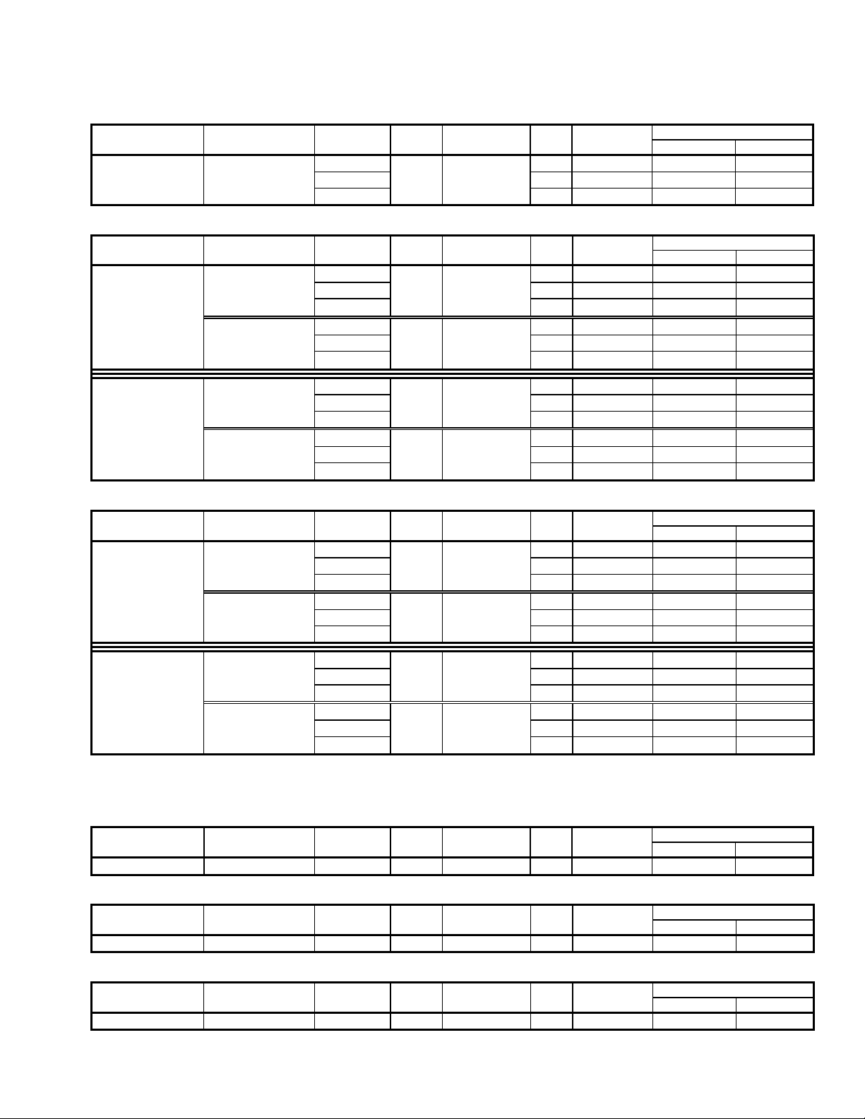
Weights and Capacities
Brewer Model Weight
(empty)
Water tank
Capacity & Weight.
Weight
(filled)
*Dispenser
Weight, ea.
*Dispenser
Filled, ea..
*Total Weight Brewer &
Dispensers, Filled
CBS-2051e 55 lbs. 5.5 gal. 46 lbs. 81 lbs. 10.5 lbs. 23 lbs. 104 lbs.
CBS-2052e 92 lbs. 10.3 gal. 86 lbs. 178 lbs. 10.5 lbs. 23 lbs. 224 lbs.
CBS-2052e20 95 lbs. 10.3 gal. 86 lbs. 181 lbs. 11.5 lbs. 28 lbs. 237 lbs.
* Based on L3D Series Dispensers
3
Electrical Configuration and Brewing Efficiency
US & Canada
CBS-2051e
1.5 gallons per batch
Electrical Heater Voltage Maximum Batches per Hour* (max 11)
Config. Code Configuration (AC) Phase Wires KW Amp draw Cold Water Hot Water
E51016 2 X 3 KW 120/208 4.6 22.1 7.7 11.0
120/220 single 3 + ground 5.1 23.4 8.6 11.0
120/240 6.1 25.5 10.3 11.0
CBS-2052e 1.5 gallons per batch
Electrical Heater Voltage Maximum Batches per Hour* (max 22)
Config. Code Configuration (AC) Phase Wires KW Amp draw Cold Water Hot Water
E52016 Option 1 120/208 4.6 22.4 7.7 18.6
Universal 2 X 3 KW 120/220 single 3 + ground 5.1 23.7 8.6 20.8
Wiring
(Factory Setting)
120/240 6.1 25.8 10.3 22.0
Total 3 X 3 KW
Option 2 120/208 6.9 19.5 11.5 22.0
Heaters 3 X 3 KW 120/220 three 4 + ground 7.7 20.6 12.9 22.0
120/240 9.1 22.5 15.4 22.0
E52026 Option 1 120/208 7.6 36.9 12.8 22.0
Universal 2 X 5 KW 120/220 single 3 + ground 8.5 39.0 14.4 22.0
Wiring
120/240 10.1 42.5 17.1 22.0
Total 3 X 5 KW
Option 2 120/208 11.4 32.0 19.2 22.0
Heaters 3 X 5 KW 120/220 three 4 + ground 12.7 33.9 22.0 22.0
(Factory Setting)
120/240 15.1 36.9 22.0 22.0
CBS-2052e20 2.0 gallons per batch
Electrical Heater Voltage Maximum Batches per Hour* (max 18)
Config. Code Configuration (AC) Phase Wires KW Amp draw Cold Water Hot Water
E53016 Option 1 120/208 4.6 22.4 5.8 14.0
Universal 2 X 3 KW 120/220 single 3 + ground 5.1 23.7 6.5 15.6
Wiring
(Factory Setting)
120/240 6.1 25.8 7.7 18.0
Total 3 X 3 KW
Option 2 120/208 6.9 19.5 8.6 18.0
Heaters 3 X 3 KW 120/220 three 4 + ground 7.7 20.6 10.1 18.0
120/240 9.1 22.5 11.6 18.0
E53026 Option 1 120/208 7.6 36.9 9.6 18.0
Universal 2 X 5 KW 120/220 single 3 + ground 8.5 39.0 11.2 18.0
Wiring
120/240 10.1 42.5 12.8 18.0
Total 3 X 5 KW
Option 2 120/208 11.4 32.0 14.4 18.0
Heaters 3 X 5 KW 120/220 three 4 + ground 12.7 33.9 16.5 18.0
(Factory Setting)
120/240 15.1 36.9
16.5 18.0
* Based on standard factory settings: 4.0 minute brew time; 0% prewet, 0% bypass; 200 F water.
Export
CBS-2051e
1.5 gallons per batch
Electrical Heater Voltage Maximum Batches per Hour* (max 11)
Config. Code Configuration (AC) Phase Wires KW Amp draw Cold Water Hot Water
E51026 2 X 3 KW 220 single 2 + ground 5.1 23.4 8.9 11.0
CBS-2052e 1.5 gallons per batch
Electrical Heater Voltage Maximum Batches per Hour* (max 22)
Config. Code Configuration (AC) Phase Wires KW Amp draw Cold Water Hot Water
E52036 2 X 3 KW 220 single 2 + ground 5.1 23.7 8.6 20.8
CBS-2052e20 2.0 gallons per batch
Electrical Heater Voltage Maximum Batches per Hour* (max 18)
Config. Code Configuration (AC) Phase Wires KW Amp draw Cold Water Hot Water
E53036 2 X 3 KW 220 single 2 + ground 5.1 23.7 6.5 15.6
* Based on standard factory settings: 4.0 minute brew time; 0% prewet, 0% bypass; 200 F water.
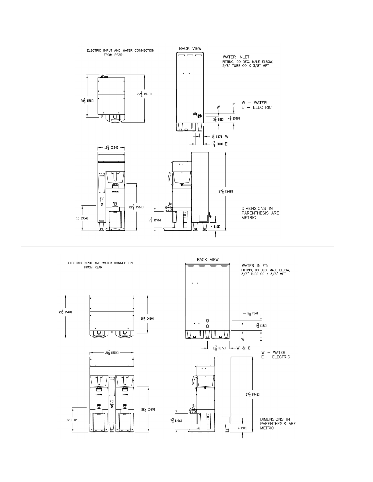
4
Dimensions & Utility Connections
DWG 201100-000
DWG 201101-000
CBS-2052e
CBS-2051e
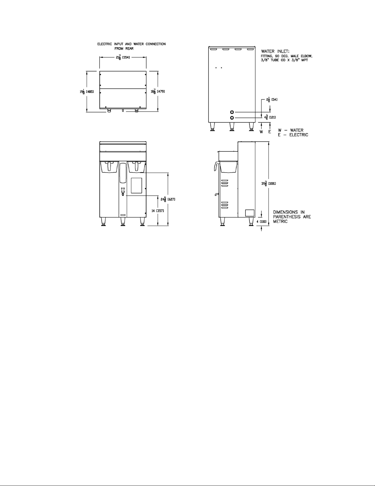
5
DWG 201129-000
CBS-2052e20
6
Installation
(For Qualified Service Technicians Only)
Keys To A Successful Installation
If not installed correctly by qualified personnel, the brewer may not operate properly and damage may result.
Damages resulting from improper installation are not covered by the warranty.
Here are the key points to consider before installation:
Electrical:
All FETCO brewers require NEUTRAL. Ground is not an acceptable substitute. Installation without neutral
may cause damage to the electronic components.
Universal wiring: This brewer can be configured for single or three phase operation. Conversion
instructions are described later in this section.
The electrical diagram and universal wiring instructions are located on the inside of the lower cover.
The installation must comply with applicable federal, state, and local codes having jurisdiction at your
location. Check with your local inspectors to determine what codes will apply.
Plumbing:
This equipment is to be installed to comply with the applicable federal, state, or local plumbing codes.
The water line must be flushed thoroughly prior to connecting it to the brewer to prevent debris from
contaminating the machine.
Verify that the water line will provide at least 1 gallon per minute for the CBS-2051e, and 1.5 gallons per
minute for the CBS-2052e and 2052e20 before connecting it to the brewer.
General:
Utilize only qualified beverage equipment service technicians for installation. A Service Company Directory
may be found on our web site, http://www.fetco.com.
Installation Instructions
Brewer Setup
1. Review the Dimensions for the unit you are installing. Verify that the brewer will fit in the space intended for it,
and that the counter or table will support the total weight of the brewer and dispensers when filled.
2. The brewer’s legs are shipped inside the brew baskets.
Remove the brew basket(s) and the coffee dispenser(s).
Place the brewer on its back and screw in the legs.
3. Place the brewer on the counter or stand.
4. When the brewer is in position, level it front to back as well
as side to side by adjusting the legs.
5. Remove the lower cover to access the water and electrical connections. Knock-outs are provided in the back
and base of the brewer body for the connections.
Water Connection
1. Water inlet is a 3/8 inch male flare fitting.
2. The brewer can be connected to a cold or hot water line. Cold water is preferred for best coffee flavor, but hot
water will allow for faster recovery times.
3. Install a water shut off valve near the brewer to facilitate service. If an in-line water filter is used, it should be
installed after the water shut off valve and in a position to facilitate filter replacement.
4. Flush the water supply line and filter before connecting it to the brewer.
5. Verify that the water line will provide at least 1 gallon per minute for the CBS-2051e, and 1.5 gallons per minute
for the CBS-2052e and 2052e20, and that the water pressure is between 20 and 75 psig.
6. Use a wrench on the factory fitting when connecting the incoming water line. This will reduce stress on the
internal connections and reduce the possibility of leaks developing after the install has been completed.
Warning: Legs are to be adjusted for
level ing the brewer only. Do not use
f or height adjustment or extend them
higher than necessary.
7
L1
L2
N
GROUND LUG
GROUND
WIRE
N
208-240V
120V 120V
Electrical Connection
1. Verify that the actual voltage at the electrical service connection is compatible with the specifications on the
brewer’s serial number label. Make sure the electrical service includes neutral.
2. The temperature and water tank fill level are pre-set at the factory. There is no need to turn off the heaters
during the installation process. The heaters are disabled by the control board until the tank is full of water. The
heating process will start automatically when the tank has filled.
3. A terminal block is provided for connecting the incoming power wires. Consult local codes to determine if a
cord and plug can be installed, or if the unit must be hard wired.
4. A fused disconnect switch or circuit breaker on the incoming power line must be conveniently located near the
brewer, and its location and markings known to the operators.
5. The body of the brewer must be grounded to a suitable building ground.
A ground lug is provided in the brewer next to the power terminal block.
Use only 10 gauge copper wire for grounding.
6. Electrical connections must be secured in-place within the unit to meet
national and local standards.
7. Connect the incoming power wires to the terminal block in accordance with applicable codes.
CBS-2051e
The CBS-2052e and CBS-2052e20 are shipped from the factory configured for either single phase or three
phase operation, depending on the version that was ordered. A tag attached to the terminal block will indicate
which way the unit was configured.
Notice: The following conversion should be performed only by a qualified beverage equipment
service technician or electrician.
For brewers manufactured before August, 2005:
To change the configuration, arrange the heater wires as shown below. Make sure that all connections are
tight. These instructions are also located on the inside of the lower cover.
GROUND
LUG
GROUND
WIRE
L1
L2
L3
N
120V
N
208-240V
NOT
USED
1 & 2
4 & 5
3 & 6
HEATER WIRES
CBS-2052e
SINGLE PHASE
CONFIGURATION
120/208-240 VAC
3 wires + ground
GROUND
LUG
GROUND
WIRE
120V
N
208-240V 208-240V
208-240V
1 & 2 3 & 4
5 & 6
HEATER WIRES
CBS-2052e
THREE PHASE
CONFIGURATION
120/208-240 VAC
4 wires + ground
L1
L2
L3
N
Incoming Power: Connect wires to L1, L2, N, Ground
Heater Wires: Connect wires 1 & 2 to L1
Connect wires 4 & 5 to L2
Connect wires 3 & 6 to L3
Incoming Power: Connect wires to L1, L2, L3, N, Grnd
Heater Wires: Connect wires 1 & 2 to L1
Connect wires 3 & 4 to L2
Connect wires 5 & 6 to L3
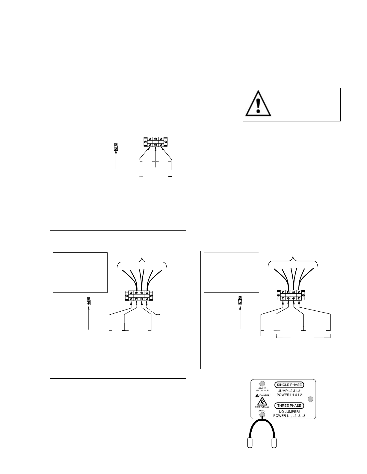
For brewers manufactured after August 1, 2005:
A jumper wire with instruction tag is provided (pictured at right).
Single Phase: Connect the jumper to L2 and L3.
Connect incoming wires to L1, L2, N, ground.
Three Phase: Do not use the jumper.
Connect wires to L1, L2, L3, N, ground.
When not used, the jumper should remain secured inside the
brewer for future use.
W arning: To prevent
electrical shock, this
unit must be properly
groun ded.
8
Final Setup
1. Turn on the incoming water supply line and inspect both inside and
outside of the brewer for leaks in all fittings and tubes
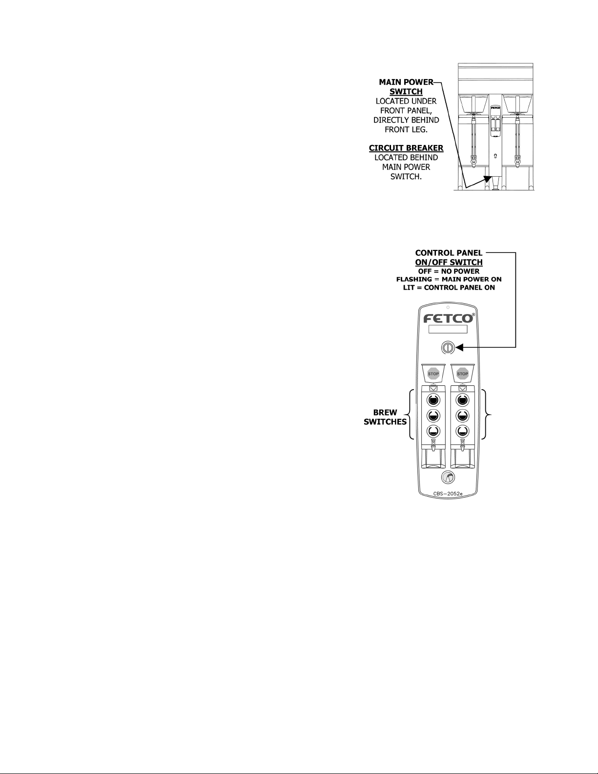
2. Turn on the incoming power.
3. Press the brewer’s main power switch, which is hidden behind the
front leg of the brewer. The control panel on/off switch will begin
flashing. Press this switch.
4. Within 6 seconds, the hot water tank will begin filling until the water is
sensed by the probe at the top of the tank. The display will read
“FIL”. The heaters will be disabled by the control board until the tank
is full.
5. While the water is heating, the display will read “LO” and the actual
water temperature will be displayed. After the water has reached the
set temperature, the display will be blank. There is no “ready” light.
6. Review the Operating Instructions. Brew one full batch (water only)
on each side to confirm proper fill levels. The brewer is factory set
with water only (no coffee) to dispense the correct amount of water.
If the actual volume is slightly different from the programmed volume,
fine tuning the brewer may be necessary. See #60 – 63 in the
Advanced Settings & Diagnostics section.
7. Re-attach the covers after one final inspection for leaks. Look
closely in the top of the brewer at the dispense fittings during this
inspection.
Operator Training
Review the operating procedures with whoever will be using the brewer.
Pay particular attention to the following areas:
1. Always pre-heat the dispensers before the first use of each day by
filling them half way with hot water, and letting them stand for at least
15 minutes.
2. Don't remove the brew basket until it has stopped dripping.
3. Make sure the dispenser is empty before brewing into it.
4. Show how to attach covers, close, and or secure the thermal
dispensers for transporting.
5. Show the location and operation of the water shut off valve as well as
the circuit breaker for the brewer.
6. Steam from the tank will form condensation in the vent tubes. This
condensation will drip into and then out of the brew baskets. 1/4 cup
discharging overnight is possible. Place an appropriate container
under each brew basket when not in use.
7. We recommend leaving the power to the brewer on overnight. The
water tank is well insulated and will use very little electricity to keep
the tank hot. Leaving the brewer in the on position will also avoid
delays at the beginning of shifts for the brewer to reach operating
temperature.
 Loading...