

Page 1
Ferm BV • P.O. Box 134 • 8280 AC Genemuiden • NL • www.ferm.com 0301-09
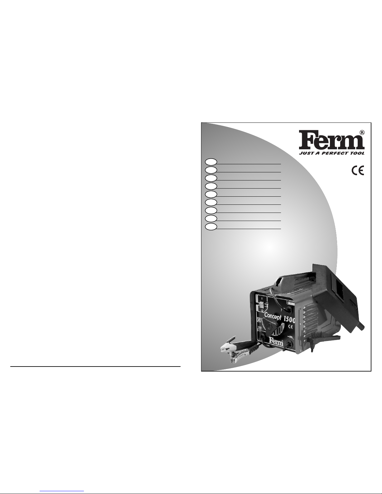
Art.nr. 125020
CONCEPT 1500
UK
D
NL
F
S
SF
N
DK
R
USERS MANUAL 03
GEBRAUCHSANWEISUNG 07
GEBRUIKSAANWIJZING 12
MODE D’EMPLOI 16
BRUKSANVISNING 21
KÄYTTÖOHJE 25
BRUKSANVISNING 30
BRUGERVEJLEDNING 34
кмдйЗйСлнЗй ий щдлигмДнДсаа 39
UK Subject to change
D Änderungen vorbehalten
NL Wijzigingen voorbehouden
F Sous réserve de modifications
S Ändringar förbehålles
SF Pidätämme oikeuden muutoksiin
N Rett till endringer forbeholdes
DK Ret til ændringer forbeholdes
RäУПО‡МЛfl Ferm ФУТЪУflММУ ТУ‚В¯ВМТЪ‚Ы
ВЪ ‚˚ФЫТН‡ВПЫ ˛ В˛ ФУВ‰ЫНˆЛ˛.
иУБЪУПЫ ‚ ЪВıМЛ˜ВТЛВ ı‡‡НЪВЛТЪЛНЛ
ПУ„ЫЪ ‚МУТЛЪ¸Тfl ·ВБ ФВ‰‚‡ЛЪВО¸МУ„У
Ы‚В‰УПОВМЛfl.
Page 2
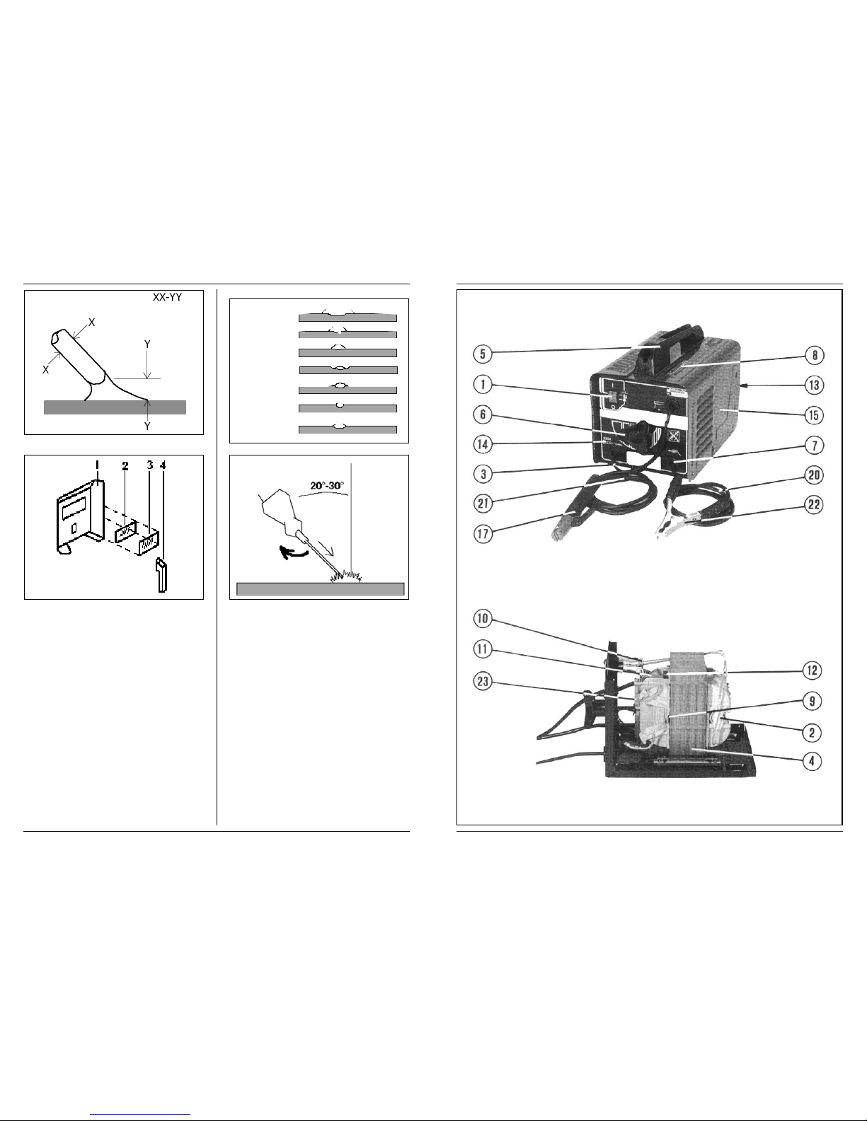
Fig.A
Fig.B
Fig.C
Fig.D
2 Ferm
Ferm 47
EXPLODED VIEW
Page 3
46 Ferm
SPARE PARTS LIST CONCEPT 1500
REF NR DESCRIPTION FERM NR
001 SWITCH (5 CONT. POINTS) 100357
002 THERMAL FUSE 100015
005 GRIP 100009
006 HANDWHEEL + ADJUSTMENT SCREW (23CM) 100010
006 HANDWHEEL + ADJUSTMENT SCREW (26CM) 100011
007 PULL RELIEF 101737
010 CURRENT INDICATOR 100003
011 SHUNT 101426
012 SPRING FOR SHUNT 102152
013 BACKPANEL 100008
- SWITCH (4 CONT.POINTS) 100004
- SCALING HAMMER/STEEL WIRE BRUSH 100005
- WELDING GLASS 140500
- WELDING MASK (EXCL. GLASS) 100007
WELDING MACHINE
THE NUMBERS IN THE FOLLOWING TEXT CORRESPOND WITH THE PICTURES AT PAGE 2
TECHNICAL SPECIFICATIONS
DESCRIPTION
EN 50060 Standard relative to welders for limited
use.
Onephase transformer.
P (W) Power in Watts.
Uo (V) No-load voltage in Volt.
f (Hz) Mains frequency in Herz.
I2 (A) Conventional welding current in ampère.
d (mm) Diameter of electrodes in mm.
nc Number of electrodes starting at room
temperature until thermostat intervenes.
nh Number of weldable electrodes after.
thermostat intervenes in first hour.
U1 (V) Mains voltage in Volt.
I1Max (A) Maximum absorbed current. Value in
ampère of use or automatic switch.
Fuse.
IP21 Protection grade covering.
H Class of isolation of transform.
Thermostat.
Collet.
Work collet.
Standardized plug.
ACCESSORIES AND SPARE PARTS
The following is supplied with your welding machine:
• Manual
• Cables
• Work clamp
• Collet clamp
• Protective mask
• Scaling hammer
• Steelbrush.
Spare parts are available through your local Ferm dealer.
When ordering parts, use the numbers listed in the Parts
List. Parts without an number are not available.
SAFETY INSTRUCTIONS
The following symbols are used in these instructions for
use:
Denotes risk of personal injury, loss of life or
damage to the tool in case of non-observance of the
instructions in this manual.
Denotes risk of electric shock.
Carefully read this manual before using the machine.
Make sure that you know how the machine functions and
how to operate it. Maintain the machine in accordance
with the instructions to make sure it functions properly.
Keep this manual and the enclosed documentation with
the machine.
When using electric machines always observe the
safety regulations applicable in your country to
reduce the risk of fire, electric shock and personal
injury. Read the following safety instructions and
also the enclosed safety instructions.
SPECIAL SAFETY RULES
• Arc welding produces sparks and fused metal projectiles and fumes: remove all flammable substances and
materials from work area.
• Provide adequate ventilation of facilities where welding takes place. Arc welding emits fumes which can
be dangerous.
• Do not weld on containers or pipes which hold or
have held flammable liquid or gaseous combustibles
(danger of explosions and/or fires) or on materials
cleaned with chlorinated solvents or on varnished
surface (danger of toxic fumes).
• Make sure connection is correct from welder to supply (mains connection). Any electric shock received
is potentially lethal.
• Avoid stretching the supply cable; unplug before
moving machine.
• Keep welding cables, elektrode holder and work
clamp in good condition; wearing out of isolation and
structural parts carrying current is DANGEROUS
and results in poor welding quality.
• Avoid direct contact with welding circuit. The noload voltage between collet and work clamp can be
dangerous.
• Do not use the machine in damp or wet places and do
not weld in the rain.
• Always protect your eyes with the fitting glasses
(grade DIN 9 - 10) equipped with this machine.
• Use gloves and proper protective clothing which are
dry and not soiled by oil or grease.
• Avoid exposing skin to the ultraviolet rays produced
by the arc. The light radiation produced by the arc can
damage eyesight and cause burns on the skin.
• This welder is automatically protected from thermic
overheating (thermostat automatic re-start). When
the windings reach performance temperature, the
protection cuts off the supply circuit. After a few
minutes cooling the protection will reopen the supply line. The welder is ready for further use.
Mains voltage | 230 V~
Frequency | 50 Hz
Absorbed power max. | 2.5 kVA
Welding current | 40 - 140 A
No load voltage | 45 - 48 V
Usable electrodes | 1.5 - 3.15 mm
Weight | 14.0 kg
UK
English
Ferm 3
Page 4
Ferm 45
• When you’re scaling off the welding slack, protect
yourself from the hot iron by using eyeprotection
and gloves.
• The workpiece can misform during cooling off. Take
care.
IMMEDIATELY SWITCH OFF THE MACHINE
IN CASE OF:
• Malfunction of the mainsplug, -socket or damaged
cables.
• Broken switch.
• Smoke or smell caused by scorched insulation.
MAKE SURE THESE SAFETY RULES ARE NOT
BROKEN, OTHERWISE THE GUARANTEE PROVISIONS WILL BE CANCELLED.
ELECTRICAL SAFETY
Always check that the mains voltage corresponds
to the voltage on the rating plate.
Replacing cables or plugs
Immediately throw away old cables or plugs when they
have been replaced by new ones. It is dangerous to insert
the plug of a loose cable in the wall socket.
Connect to the mains cable a standardized plug of adequate capacity to which the yellow/green conductor of
the cable is to be connected. Set a standardized plug
equipped with fuses or an automatic switch; the correct
terminal is to be grounded to the distribution mains. Use
fuses of 16 Ampère Slow as a minimum.
Immediately throw away old cables or plugs when they
have been replaced by new ones. It is dangerous to insert
the plug of a loose cable in the wall outlet.
Using extension cables
Only use an approved extension cable suitable for the
power input of the machine. The minimum conductor
size is 1.5 mm2. When using a cable reel always unwind
the reel completely.
BEFORE OPERATING THE
MACHINE
EXECUTION OF WELD
Fig.A
After carrying out all electrical connections necessary
both on mains and welding circuits proceed in the following way. Arc welding with an elektric welding machine
is a method in which the warmth is delivered by the arc.
This arc is made between the electrode and the workpiece.
NB: Before carrying out difficult welds do a practise run,
only practice will allow you to obtain a neat and durable
weld.
The temperature of the arc is 4000° Celsius what makes
the electrode and the workpiece melt. As long as the arc
is maintained the electrode will melt and it will supply the
material for the connection.
The distance between the electrode and the workpiece
must be 1.5 - 4 mm, depending on the diameter of the
electrode and the material it is made of. The required
welding current is supplied by the welding machine. The
required capacity of the welding machine depends on the
connections to be made.
THE ELECTRODE
The electrode consists of an iron core with cover. This
cover consists partly of irondust. While welding the
cover will melt and it will vapor. This way a gas surrounds
the welding area protecting the melted iron from oxygen
in the air. Some parts of the cover will floot on the melted
iron (it is of less weight than the iron) and it will protect
the iron while cooling off. After cooling this cover can be
removed easily by a scaling hammer or steelbrush. Make
sure the cover of the electrode is not incapsulated by the
iron. This would make an unreliable connection.
Treat the electrodes with caution. The cover can be
damaged and this will make the welding very diffi-
cult. Make sure the electrodes are stored cool and dry.
Choice of the electrode
To make a good connection it is important to choose the
right electrode. Also the position in which you have to
make the connection, for example above your head, is
important while choosing the electrode. A normal elektrode can do most ordinary welding jobs.
Electrodes are available in three types:
1. Fast solidification
The cover consists of a lot organic material, which
give a good gasprotection. It can be used in all kinds of
positions, specially for vertical, downgoing connections.
2. Medium solidification
The cover consists of a lot organic material. Good
welding in all positions except vertical, downgoing
connections. They are useful for vertical, upgoing
connections.
4 Ferm
Page 5

3. Slow solidification
The cover is thicker than the other two types and
consists less organic material. Thick compact slack.
The meltingbath is very thin liquid. Connections
most of the time in horizontal direction. For welding
aluminium and stainless steel special electrode are
available. Ask for advice from your local Ferm-dealer.
PERFORMANCE
The performance of this welder may be expressed by the
number of electrodes : nc and nh.
nc: Refers to the number of electrodes which may be
welded when the welder commences at room temperature until the thermostat intervenes.
nh: Refers to the AVERAGE VALUE of the number of
electrodes which may be welded between re-start and
intervention of thermostat, in the first hour of use.
WELDINGCURRENT
By turning the wheel clockwise the current is increased.
By turning the wheel counter-clockwise the current is
decreased. The value of the current (I2) may be read on
the graduated scale on the upper panel and corresponds
to the voltage of the arc (U2) according to the equation
U2(V)=18 + 0,04 x I2 (EN 50060). When you’re using
long extension cables, the current is reduced considerably. The required current also depends on the size of the
workpiece. Small workpieces require a smaller current.
Workpiece Electrode core Welding
thickness Ø (mm2) current (A)
2 - 3 2 4 5 - 6 5
4 - 5 2,5 70 - 95
6 - 7 3,25 90 - 130
8 - 12 4 130 - 160
Tab.1
OPERATING THE MACHINE
COLLET CABLE
This has a special clamp on the terminal to attach to the
exposed part of the electrode.
WORK CABLE
This must be directly connected to the workpiece or the
work bench.
Make sure contact to workpiece is adequate by
avoiding varnished surfaces and/or non-metallic
materials.
PROTECTIVE MASK
Fig.B
This must ALWAYS be used during welding and protects
the eyes from the light radiation produced by the arc.
The mask alows observation of the welding being carried
out.
1. Mask
2. Glass
3. Filter
4. Handgrip
Assemble the welding glass and the cover glass,
before you begin to weld.
Never look directly into the arc without the use of a protective
mask.
SCALING HAMMER
With this hammer the slack of the welded connection
can be removed. Do not hit too hard, otherwise the connection will be damaged. Always use safety glasses.
STEELBRUSH
With this steelbrush you can remove rust before attaching the work cable to the workpiece or to remove the
slack after welding.
CHARACTERISTICS OF THE WELD SEAM
Fig.C
1. Advancement too low
2. Excessive advancement
3. Arc too short
4. Arc too long
5. Current too low
6. Current too high
7. Current correct
Ferm 544 Ferm
Page 6
нЦпзауЦлдйЦ
йЕлгмЬаЗДзаЦ
иЛ У·ТОЫКЛ‚‡МЛЛ Л ˜ЛТЪНВ ‡ФФ‡‡Ъ‡
Ы·В‰ЛЪВТ¸ ‚ ЪУП, ˜ЪУ УМ У·ВТЪУ˜ВМ
(¯ЪВФТВО¸М‡fl ‚ЛОН‡ ‚˚МЫЪ‡ ЛБ УБВЪНЛ).
аБ‰ВОЛfl ЩЛП˚ Ferm ТНУМТЪЫЛУ‚‡М˚ Ъ‡НЛП
У·‡БУП, ˜ЪУ·˚ ‡·УЪ‡Ъ¸ ·ВБ ФУ·ОВП Л ФЛ
ПЛМЛП‡О¸МУП ЪВıМЛ˜ВТНУП У·ТОЫКЛ‚‡МЛЛ М‡
ФУЪflКВМЛЛ ФУ‰УОКЛЪВО¸МУ„У ‚ВПВМЛ.
кВ„ЫОflМ˚И ЫıУ‰ Л ˜ЛТЪН‡, ‡ Ъ‡НКВ ЪВıМЛ˜ВТНЛ
„‡ПУЪМУВ У·‡˘ВМЛВ Т ‚‡¯ЛП ‡ФФ‡‡ЪУП
ФУ‰ОВ‚‡˛Ъ ТУН В„У ТОЫК·˚.
уЛТЪН‡
ЗУ ЛБ·ВК‡МЛВ ФВ„‚‡ ˝ОВНЪУПУЪУ‡ ‡ФФ‡‡Ъ‡ В„У
‚ВМЪЛОflˆЛУММ˚В УЪ‚ВТЪЛfl ‰УОКМ˚ ТУ‰ВК‡Ъ¸Тfl ‚
˜ЛТЪУЪВ. зВУ·ıУ‰ЛПУ В„ЫОflМУ ˜ЛТЪЛЪ¸ НУФЫТ
‡ФФ‡‡Ъ‡ Т ЛТФУО¸БУ‚‡МЛВП Пfl„НУИ Т‡ОЩВЪНЛ ЛБ
ЪН‡МЛ, КВО‡ЪВО¸МУ, ФУТОВ Н‡К‰У„У ЛТФУО¸БУ‚‡МЛfl.
тОЛˆВ‚˚В ‚ВМЪЛОflˆЛУММ˚В Ф‡Б˚ ‰УОКМ˚ ·˚Ъ¸
Т‚У·У‰М˚ УЪ Б‡„flБМВМЛИ Л Ф˚ОЛ.
зВФУО‡‰НЛ
З ТОЫ˜‡В ‚УБМЛН¯Лı МВФУО‡‰УН, М‡ФЛПВ, ЛБ-Б‡
ЛБМУТ‡ ‰ВЪ‡ОЛ, У·‡˘‡ИЪВТ¸ Н З‡¯ВПЫ ПВТЪМУПЫ
‰ЛОВЫ ЩЛП˚ Ferm. з‡ У‰МУИ ЛБ ФУТОВ‰МЛı ТЪ‡МЛˆ
ЫНУ‚У‰ТЪ‚‡ ФЛ‚В‰ВМ‡ ТıВП‡ ‡ФФ‡‡Ъ‡ ‚
‡БУ·‡ММУП ‚Л‰В, „‰В ФУН‡Б‡М˚ ‰ВЪ‡ОЛ, НУЪУ˚В
ПУКМУ Б‡Н‡Б‡Ъ¸ ‚Б‡ПВМ МВЛТФ‡‚М˚ı.
бДфанД йдкмЬДыфЦв лкЦСх
уЪУ·˚ ФВ‰УЪ‚‡ЪЛЪ¸ ‚УБМЛНМУ‚ВМЛВ ФУ‚ВК‰ВМЛИ
‚У ‚ВПfl Ъ‡МТФУЪЛУ‚НЛ, ЛБ‰ВОЛВ ФУТЪ‡‚ОflВЪТfl ‚
ФУ˜МУИ ЫФ‡НУ‚НВ. мФ‡НУ‚Н‡ ТУТЪУЛЪ ‚ УТМУ‚МУП ЛБ
П‡ЪВЛ‡ОУ‚, ФЛ„У‰М˚ı ‰Оfl ‚ЪУЛ˜МУИ ФВВ‡·УЪНЛ.
иУ˝ЪУПЫ ЛТФУО¸БЫИЪВ ‚УБПУКМУТЪ¸ ‰Оfl Т‰‡˜Л
ЫФ‡НУ‚НЛ ‚ ФЫМНЪ˚ ‚ЪУЛ˜МУИ ФВВ‡·УЪНЛ. ЦТОЛ ‚‡П
·УО¸¯В МВ МЫКВМ УЪТОЫКЛ‚¯ЛИ ТЪ‡˚И ‡ФФ‡‡Ъ, ЪУ
‰УТЪ‡‚¸ЪВ В„У ‚‡¯ВПЫ ПВТЪМУПЫ ‰ЛОВЫ ЩЛП˚ Ferm.
н‡П ФУБ‡·УЪflЪТfl У· ˝НУОУ„Л˜ВТНЛ ˜ЛТЪУИ В„У
ФВВ‡·УЪНВ.
ЙДкДзнаь
Й‡‡МЪЛИМ˚В ЫТОУ‚Лfl ФЛ‚У‰flЪТfl М‡ ТФВˆЛ‡О¸МУП
„‡‡МЪЛИМУП Ъ‡ОУМВ, НУЪУ˚И ФЛО‡„‡ВЪТfl УЪ‰ВО¸МУ.
иУ‰ М‡¯Ы ЛТНО˛˜ЛЪВО¸МЫ˛ УЪ‚ВЪТЪ‚ВММУТЪ¸
Û‰ÓÒÚÓ‚ÂflÂÏ, ˜ÚÓ ‰‡ÌÌÓ ËÁ‰ÂÎËÂ
Û‰Ó‚ÎÂÚ‚ÓflÂÚ ÒÎÂ‰Û˛˘ËÏ
Òڇ̉‡Ú‡Ï Ë ÌÓχÚË‚Ì˚Ï
‰УНЫПВМЪ‡П Цл:
EN50060 + ‰УФУОМВМЛВ,
EN50199 + ‰УФУОМВМЛВ
EN60974-1 + ‰УФУОМВМЛВ,
Òӄ·ÒÌÓ ÒÎÂ‰Û˛˘ËÏ Ô‰ÔËÒ‡ÌËflÏ:
LDV 73/23 EEC + ‰УФУОМВМЛВ
EMC 89/336 + ‰УФУОМВМЛВ
20.09.2002
ЙЦзЦейвСЦз,
зЛ‰ВО‡М‰˚
Ç. ä‡ÏÔıÓÙ
éÚ‰ÂÎ ÍÓÌÚÓÎfl ͇˜ÂÒÚ‚‡
CE
ı
ДЕКЛАРАЦИЯ О СООТВЕТСТВИИ ВЕЛИКОБРИТАНИЯ
(R)
Ferm 43
WELDING
Fig.D
• Insert the exposed part of the electrode into the collet and connect the work clamp to the welding piece
taking care that electric contact is good.
• Turn on welder and regulate welding current in function of the electrode in use.
• Holding the mask IN FRONT OF FACE stroke the
electrode point on the workpiece as if striking a
match. This is the most correct method for striking
the arc.
Don’t hit the electrode on the workpiece, which will
damage the stick electrode and make arc strike-up
difficult.
• Immediately after arc strike up try to maintain a distance from the workpiece which is equivalent to the
diameter of the electrode used. Maintain this distance as constantly as possible during the weld,
remember that the inclination of the electrode to the
advancement must be 20° - 30°.
Always use pliers to remove consumed electrodes
or to move welded pieces.
MALFUNCTION
Below we have listed a number of possible causes and
corresponding solutions in case the machine does not
function as it should:
When the welding machine doesn’t function,
check the following
• The thermal fuse is disconnected.
• The fuse is defect (mains).
• The work cable is not connected with the workpiece.
• The collet or work cable or the mains supply is damaged.
MAINTENANCE
Make sure that the machine is not live when carrying out maintenance work on the motor.
The Ferm machines have been designed to operate over
a long period of time with a minimum of maintenance.
Continuous satisfactory operation depends upon proper machine care and regular cleaning.
Cleaning
Keep the ventilation slots of the machine clean to prevent overheating.
Regularly clean the machine housing with a soft cloth,
preferably after each use. Keep the ventilation slots free
from dust and dirt.
Faults
Should a fault occur, e.g. after wear of a part, please contact your local Ferm dealer.
In the back of this manual you find an exploded view
showing the parts that can be ordered.
ENVIRONMENT
In order to prevent the machine from damage during
transport, it is delivered in a sturdy packaging. Most of
the packaging materials can be recycled. Take these
materials to the appropriate recycling locations.
Take your unwanted machines to your local Fermdealer. Here they will be disposed of in an environmentally safe way.
6 Ferm
Page 7
GUARANTEE
The guarantee conditions can be found on the separately
enclosed guarantee card.
We declare under our sole responsibility that this
product is in conformity with the following
standards or standardized documents
EN50060 + Amdt,
EN50199 + Amdt
EN60974-1 + Amdt,
in accordance with the regulations:
LDV 73/23 EEC + Amdt
EMC 89/336 + Amdt
from 20-09-2002
GENEMUIDEN NL
W. Kamphof
Quality department
SCHWEIßGERÄT
DIE NUMMERN IM NACHFOLGENDEN TEXT
KORRESPONDIEREN MIT DER ABBILDUNGEN
AUF SEITE 2
TECHNICAL SPECIFICATIONS
BESCHREIBUNG VON SYMBOLE
EN 50060 Schweißnorm für limitierte Nutzung.
Einphasentrafo.
Uo (V) Leerspannung in Volt.
f(Hz) Netzfrequenz in Herz.
I2(A) Secundair- oder Schweißstrom in
Ampère.
d(mm) Schweißelektrodendurchmeßer in mm.
nc Schweißelektrodennummer vom kalten
Zustand bis zum ersten Einsetzen des
Thermostats.
nh Elektrodennummer nach dem ersten
Einsetzen des Thermostats in der ersten
Benützungsstunde.
U1(V) Netzspannung in Volt
I1(A) Maximaler Aufnahmestrom in Ampère
Sicherung
IP21 Schutzgrad der Schutzhüle
H Isolierungsklasse des Trafos
Thermostat
Elektrodenhalter
Erdungsklemme
Normstecker
ZUBEHÖR UND ERSATZTEILE
Bei das Schweißgerät wird als Standard mitgeliefert:
• Gebrauchsanweisung
• Kabel
• Erdungsklemme
• Elektrodenhalter
• Schutzmaske
• Pickhammer
• Stahlbürste
Über Ihren Ferm-Händler können Sie Ersatzteile nachbestellen, die in Vorrat gehalten werden. Beim Bestellen
der Ersatzteile sollten Sie die Nummern benutzen, die in
der Unterteil-Liste aufgeführt sind.
Netzanschluß | 230 V~
Frequenz | 50 Hz
Max. Leistungsaufnahme | 2.5 kVA
Schweißstrom | 40 - 140 A
Leerlaufspannung | 45 - 48 V
Elektrodenstärke | 1.5 - 3.15 mm
Gewicht | 14.0 kg
Deutsch
D
CE
ı
DECLARATION OF CONFORMITY
(UK)
Ferm 7
щдлигмДнДсаь ДииДкДнД
дДЕЦгъ щгЦднкйСйСЦкЬДнЦгь
аПВВЪ ТФВˆЛ‡О¸М˚И Б‡КЛП М‡ НОВППВ ‰Оfl НВФОВМЛfl
У„УОfiММУИ ˜‡ТЪЛ ˝ОВНЪУ‰‡.
дДЕЦгъ «еДллх»
СУОКВМ ·˚Ъ¸ МВФУТВ‰ТЪ‚ВММУ ФЛНВФОВМ Н
ЛБ‰ВОЛ˛ ЛОЛ ЪУНУФУ‚У‰fl˘ВПЫ ‡·У˜ВПЫ ТЪУОЫ.
м·В‰ЛЪВТ¸, ˜ЪУ Н‡·ВО¸ «П‡ТТ˚» М‡‰ВКМУ
ТУВ‰ЛМfiМ Т ЛБ‰ВОЛВП Л ЪУ˜Н‡ ТУВ‰ЛМВМЛfl МВ
ФУН˚Ъ‡ ЛБУОЛЫ˛˘ЛП П‡ЪВЛ‡ОУП, М‡ФЛПВ, О‡НУП.
бДфанзДь еДлдД
êËÒ.B
б‡˘ЛЪМ‡fl П‡ТН‡ ‰УОКМ‡ У·flБ‡ЪВО¸МУ ЗлЦЙСД
ЛТФУО¸БУ‚‡Ъ¸Тfl ФЛ Т‚‡НВ. йМ‡ Б‡˘Л˘‡ВЪ „О‡Б‡ УЪ
Т‚ВЪУ‚У„У ЛБОЫ˜ВМЛfl ‰Ы„Л. е‡ТН‡ ФУБ‚УОflВЪ
М‡·О˛‰‡Ъ¸ Б‡ ‚˚ФУОМВМЛВП ФУˆВТТ‡ Т‚‡НЛ.
1. å‡Ò͇
2. лЪВНОУ
3. л‚ВЪУЩЛО¸Ъ
4. êÛÍÓflÚ͇
иВВ‰ М‡˜‡ОУП Т‚‡НЛ МЫКМУ ТУ·‡Ъ¸
Т‚‡У˜МУВ ТЪВНОУ Л ФУНУ‚МУВ ТЪВНОУ.
д‡ЪВ„УЛ˜ВТНЛ Б‡ФВ˘‡ВЪТfl ТПУЪВЪ¸ ФflПУ М‡
Т‚‡У˜МЫ˛ ‰Ы„Ы ·ВБ Б‡˘ЛЪМУИ П‡ТНЛ!
ейгйнйд Сгь йдДгазх
л ФУПУ˘¸˛ ˝ЪУ„У ПУОУЪН‡ Ы‰‡ОflВЪТfl ¯О‡Н ТУ
Т‚‡МУ„У ТУВ‰ЛМВМЛfl. зВ ТОВ‰ЫВЪ Ы‰‡flЪ¸ ПУОУЪНУП
ТОЛ¯НУП ТЛО¸МУ. щЪУ ПУКВЪ ФЛ‚ВТЪЛ Н
ФУ‚ВК‰ВМЛ˛ ¯‚‡. иЛ ˝ЪУП ‚ТВ„‰‡ ЛТФУО¸БЫИЪВ
Б‡˘ЛЪМ˚В У˜НЛ.
икйЗйгйузДь фЦндД
л ФУПУ˘¸˛ ˘ВЪНЛ ЛБ ТЪ‡О¸МУИ ФУ‚УОУНЛ ПУКВЪ
Ы‰‡ОflЪ¸Тfl К‡‚˜ЛМ‡ ФВВ‰ НВФОВМЛВП Н‡·ВОfl Н
Т‚‡У˜МУИ ‰ВЪ‡ОЛ ЛОЛ КВ Ы‰‡ОflЪ¸Тfl ¯О‡Н ФУТОВ
Т‚‡НЛ.
пДкДднЦкалнада лЗДкзхп тЗйЗ
êËÒ.C
1лОЛ¯НУП ПВ‰ОВММУВ ‚В‰ВМЛВ
2 лОЛ¯НУП ·˚ТЪУВ ‚В‰ВМЛВ
3й˜ВМ¸ НУУЪН‡fl ‰Ы„‡
4 й˜ВМ¸ ‰ОЛММ‡fl ‰Ы„‡
5 лОЛ¯НУП П‡О˚И ЪУН
6 лОЛ¯НУП ·УО¸¯УИ ЪУН
7 йФЪЛП‡О¸М˚И ЪУН
лЗДкдД
êËÒ.D
• ЗТЪ‡‚¸ЪВ У„УОfiММЫ˛ ˜‡ТЪ¸ ˝ОВНЪУ‰‡ ‚
˝ОВНЪУ‰У‰ВК‡ЪВО¸ Л ФЛТУВ‰ЛМЛЪВ Б‡КЛП
Н‡·ВОfl «П‡ТТ˚» Н Т‚‡Л‚‡ВПУИ ‰ВЪ‡ОЛ,
Ы·В‰Л‚¯ЛТ¸ ‚ М‡ОЛ˜ЛЛ ıУУ¯В„У ˝ОВНЪЛ˜ВТНУ„У
НУМЪ‡НЪ‡.
• ЗНО˛˜ЛЪВ Т‚‡У˜М˚И ‡ФФ‡‡Ъ Л УЪВ„ЫОЛЫИЪВ
Т‚‡У˜М˚И ЪУН ‚ ТУУЪ‚ВЪТЪ‚ЛЛ Т ЪЛФУП
ФЛПВМflВП˚ı ˝ОВНЪУ‰У‚.
• СВК‡ П‡ТНЫ иЦкЦС гасйе, ОВ„НУ ФУ‚В‰ЛЪВ
НУМˆУП ˝ОВНЪУ‰‡ ФУ ЛБ‰ВОЛ˛, Н‡Н ·Ы‰ЪУ ‚˚
Б‡КЛ„‡ВЪВ ТФЛ˜НЫ. щЪУ Т‡П˚И Ф‡‚ЛО¸М˚И ТФУТУ·
Б‡КЛ„‡МЛfl ‰Ы„Л.
зВ Ы‰‡flИЪВ ТЛО¸МУ ˝ОВНЪУ‰УП ФУ ЛБ‰ВОЛ˛.
щЪУ ПУКВЪ ФЛ‚ВТЪЛ Н ФУ‚ВК‰ВМЛ˛
˝ÎÂÍÚÓ‰‡ Ë Á‡ÚÛ‰ÌËÚ Á‡ÊË„‡ÌË ‰Û„Ë.
• л‡БЫ ФУТОВ Б‡КЛ„‡МЛfl ‰Ы„Л ФУТЪ‡‡ИЪВТ¸
‚˚‰ВКЛ‚‡Ъ¸ ‡ТТЪУflМЛВ УЪ ЛБ‰ВОЛfl, ‡‚МУВ
‰Л‡ПВЪЫ ФЛПВМflВПУ„У ˝ОВНЪУ‰‡.
З˚‰ВКЛ‚‡ИЪВ ˝ЪУ ‡ТТЪУflМЛВ ФЛ Т‚‡НВ ФУ
‚УБПУКМУТЪЛ ‚Тfi ‚ВПfl ФУТЪУflММ˚П. иУПМЛЪВ У
ЪУП, ˜ЪУ М‡НОУМ ˝ОВНЪУ‰‡ ФУ УЪМУ¯ВМЛ˛ Н
М‡Ф‡‚ОВМЛ˛ В„У ‰‚ЛКВМЛfl ‰УОКВМ ТУТЪ‡‚ОflЪ¸
20° - 30°.
ЗТВ„‰‡ ЛТФУО¸БИЪВ ТФВˆЛ‡О¸М˚В ˘ЛФˆ˚ ‰Оfl
Ы‰‡ОВМЛfl УЪ‡·УЪ‡ММУ„У ˝ОВНЪУ‰‡ ЛОЛ
ÔÂÂÏ¢ÂÌËfl Ò‚‡ÂÌÌ˚ı ‰ÂÚ‡ÎÂÈ.
ЗйбейЬзхЦ зЦийгДСда а
еЦнйСх ап млнкДзЦзаь
зЛКВ ФЛ‚У‰ЛЪТfl fl‰ МВЛТФ‡‚МУТЪВИ, Лı
‚УБПУКМ˚В ФЛ˜ЛМ˚ Л ПВЪУ‰˚ ЫТЪ‡МВМЛfl:
ÖÒÎË Ò‚‡Ó˜Ì˚È ‡ÔÔ‡‡Ú Ì ‡·ÓÚ‡ÂÚ,
Ôӂ¸Ú ÒÎÂ‰Û˛˘ÂÂ:
• л‡·УЪ‡О ЪВПУФВ‰Уı‡МЛЪВО¸;
• иВВ„УВО ФО‡‚НЛИ ТВЪВ‚УИ ФВ‰Уı‡МЛЪВО¸;
• 䇷Âθ «Ï‡ÒÒ˚» Ì ÔËÒÓ‰ËÌÂÌ Í Ò‡ÏÓÏÛ
ËÁ‰ÂÎ˲;
• иУ‚ВК‰ВМЛВ Н‡·ВОfl ‰ВК‡ЪВОfl ˝ОВНЪУ‰‡,
Н‡·ВОfl «П‡ТТ˚» ЛОЛ ‚ ОЛМЛЛ ФУ‰‡˜Л ФЛЪ‡МЛfl.
42 Ferm
Page 8
SICHERHEITSVORSCHRIFTEN
In dieser Betriebsanleitung erscheinen folgende Piktogramme:
Verweist auf Verletzungsgefahr, Gefahr für Leben
und mögliche Beschädigung der Maschine, falls die
Anweisungen in dieser Betriebsanleitung nicht befolgt werden.
Deutet das Vorhandensein elektrischer Spannung
an.
Lesen Sie diese Betriebsanleitung aufmerksam, bevor Sie
die Maschine in Betrieb nehmen. Machen Sie sich vertraut mit der Funktionsweise und der Bedienung. Warten
Sie die Maschine entsprechend den Anweisungen, damit
sie immer einwandfrei funktioniert. Die Betriebsanleitung und die dazugehörende Dokumentation müssen in
der Nähe der Maschine aufbewahrt werden.
Bei der Verwendung von elektrischen Maschinen
sollten Sie immer die einschlägigen nationalen
Sicherheitsvorschriften befolgen um das Risiko auf
Feuer, elektrische Schläge und persönliche Verletzung zu reduzieren. Lesen Sie die nachstehenden
Sicherheitsvorschriften sowie die beigefügten
Sicherheitsanweisungen.
Diese Anweisungen sollten an einem sicheren Ort
aufbewahrt bleiben.
SPEZIELLE SICHERHEITSVORSCHRIFTEN
• Bogenschweißen erzeugt Funken, geschmolzene
Metallteile und Rauch, achten Sie darauf das keine
brandbare Gegenstände sich in der Nähe des
Arbeitsplatzes befinden.
• Überzeugen Sie sich, daß ausreichend Luftzufuhr zur
Verfügung steht.
• Schweißen Sie nicht auf Behältern. Gefäßen oder
Rohren, die brennbare Flußigkeiten oder Gase enthalten haben (Gefahr von Emission toxischer Gase).
• Vergewissen Sie sich daß das Gerät richtig an das
Netzkabel angeschloßen ist. Jeder Elektroschock
kann möglicherweise tödlich sein.
• Vermeiden sie jede Spannung des Netzkabels. Stec-
ken Sie das Gerät aus, bevor Sie es andernorts aufstellen wollen.
• Achten Sie auf den Zustand der Schweißkabel der
Elektrodenzange sowie der Erdungsklemmen.
Abnützungen an der Isolierung und an den stromführende Teilen können eine gefährliche Situation hervorrufen und die Qualität der Schweißarbeit mindern.
• Vermeiden Sie jeden direkten Kontakt mit dem Sch-
weißkreislauf; die Leerspannung die zwischen Elektrodenzange und Erdungsklemme auftritt kann
gefährlich sein.
• Verwenden Sie das Gerät nicht in feuchter oder
naßer Umgebung oder in Regen.
• Schützen sie die Augen mit dafür bestimmten Schutz-
brillen, die Sie auf der beigelegten Maske befestigen.
• Verwenden Sie Handschuhe und trockene Schutz-
kleidung, die frei von Öl und Fett ist.
• Wenn Sie die Schweißraupe mit einen Pickhammer
entfernen, benützen Sie in jeden Fall eine Schutzbrille
und Handschuhe gegen die heiße Stücke.
• Um die Haut nicht der ultravioletten Strahlung des
Bogens auszusetzen müssen Sie Schutzkleidung
benützen.
• Dieses Gerät ist gegen Thermischer Überladung
durch eine automatische Schutzeinrichtung (Thermostat mit automatischer Wiederaufnahme)
geschützt. Die Schutzvorrichtung unterbricht den
Stromkreis. Nach einigen Minuten der Abkühlung
wird das Gerät wieder aktiviert. Das Gerät ist für
weiter Arbeiten bereit.
• Das Werkstuck kann sich Verformen während das
abkühlen. Achten Sie darauf.
DAS GERÄT SOFORT AUSSCHALTEN BEI:
• Störung im Netzstecker, dem Netzkabel oder
Schnurbeschädigung.
• Defekter Schalter.
• Rauch oder Gestank verschmorter Isolation.
NICHT ERFOLGEN DER SICHERHEITSVORSCHRIFTEN HAT EINSCHRENKUNG DER
GARANTIEBEDINGUNGEN ZUFOLGE!
ELEKTRISCHE SICHERHEIT
Überprüfen Sie immer, ob Ihre Netzspannung der
des Typenschilds entspricht.
Austauschen von Kabeln oder Steckern
Entsorgen Sie alte Kabel oder Stecker, unmittelbar nachdem Sie durch neue ersetzt sind. Das Anschließen eines
Steckers eines losen Kabels an eine Steckdose ist gefährlich.
Daß Gerät muß von zwei Leitern gespeist werden und
mit einem dritten Leiter der ausschließlich für die Erdung
(PE) zuständig ist versehen sein. Dieser Leiter ist
gelb/grün. Suchen Sie sich eine Netzsteckdose die mit
einer Sicherung oder einem automatischen Unterbrecher abgesichert ist. Das vorgesehene Erdungsende muß
mit dem Erdungsnetz des Stromnetzes verbunden werden.
Benützen Sie Sicherungen von minimal 16 Ampère Langsam
Verwendung von Verlängerungskabeln
Benutzen Sie nur ein genehmigtes Verlängerungskabel,
das der Maschinenleistung entspricht. Die Ader müssen
einen Mindestquerschnitt von 1,5 mm
2
haben. Befindet
das Kabel sich auf einem Haspel. muß es völlig abgerollt
werden.
8 Ferm
иЦкЦС зДуДгйе
щлдигмДнДсаа
ЗхийгзЦзаЦ лЗДкда
êËÒ.A
иУТОВ ‚˚ФУОМВМЛfl ‚ТВı ˝ОВНЪЛ˜ВТНЛı
ФУ‰ТУВ‰ЛМВМЛИ ТВЪЛ Л Т‚‡У˜МУ„У НУМЪЫ‡
ФУЛБ‚У‰ЛЪВ Т‚‡НЫ ТОВ‰Ы˛˘ЛП У·‡БУП. СЫ„У‚‡fl
˝ОВНЪУТ‚‡Н‡ Т ФУПУ˘¸˛ ˝ОВНЪУТ‚‡У˜МУ„У
‡ФФ‡‡Ъ‡ - ˝ЪУ ПВЪУ‰ Т‚‡НЛ, ФЛ НУЪУУП
ЛТЪУ˜МЛНУП ЪВФО‡ fl‚ОflВЪТfl ‰Ы„‡. щЪ‡ ‰Ы„‡ ‚УБМЛН‡ВЪ
ПВК‰Ы ˝ОВНЪУ‰УП Л Т‚‡Л‚‡ВПУИ ‰ВЪ‡О¸˛.
èËϘ‡ÌËÂ: иВВ‰ Т‚‡НУИ ТОУКМ˚ı ¯‚У‚
‚˚ФУОМЛЪВ ФУ·МЫ˛ Т‚‡НЫ. нУО¸НУ Ф‡НЪЛН‡
ФУБ‚УОЛЪ ‚‡П ФУОЫ˜‡Ъ¸ ‡ННЫ‡ЪМ˚В Л ФУ˜М˚В ¯‚˚.
нВПФВ‡ЪЫ‡ ‰Ы„Л ТУТЪ‡‚ОflВЪ 4000° л Л ФЛ‚У‰ЛЪ Н
‡ТФО‡‚ОВМЛ˛ ˝ОВНЪУ‰‡ Л Т‚‡Л‚‡ВПУИ ‰ВЪ‡ОЛ. ЦТОЛ
‰Ы„‡ ФУ‰‰ВКЛ‚‡ВЪТfl, ˝ОВНЪУ‰ ФО‡‚ЛЪТfl Л ‰‡ВЪ
П‡ЪВЛ‡О ‰Оfl ТУВ‰ЛМВМЛfl.
к‡ТТЪУflМЛВ ПВК‰Ы ˝ОВНЪУ‰УП Л ‰ВЪ‡О¸˛ ‰УОКМУ
·˚Ъ¸ УЪ 1,5 ‰У 4,0 ПП ‚ Б‡‚ЛТЛПУТЪЛ УЪ ‰Л‡ПВЪ‡ Л
П‡ЪВЛ‡О‡ ˝ОВНЪУ‰‡. зВУ·ıУ‰ЛП˚И Т‚‡У˜М˚И ЪУН
ФУ‰‡ВЪТfl Т‚‡У˜М˚П ‡ФФ‡‡ЪУП. зВУ·ıУ‰ЛП‡fl
ПУ˘МУТЪ¸ Т‚‡У˜МУ„У ‡ФФ‡‡Ъ‡ Б‡‚ЛТЛЪ УЪ
‚˚ФУОМflВП˚ı ТУВ‰ЛМВМЛИ.
щгЦднкйСх
щОВНЪУ‰ ТУТЪУЛЪ ЛБ ПВЪ‡ООЛ˜ВТНУ„У ТЪВКМfl Л
ФУН˚ЪЛfl. иУН˚ЪЛВ ˜‡ТЪЛ˜МУ ТУТЪУЛЪ ЛБ
ПВЪ‡ООЛ˜ВТНУИ Ф˚ОЛ. иЛ Т‚‡НВ ФУН˚ЪЛВ ФО‡‚ЛЪТfl
Л ЛТФ‡flВЪТfl. й·‡БЫ˛˘ЛИТfl „‡Б УНЫК‡ВЪ БУМЫ
Т‚‡НЛ, Б‡˘Л˘‡fl ‡ТФО‡‚ОВММ˚И ПВЪ‡ОО УЪ НЛТОУУ‰‡
‚УБ‰Ыı‡. у‡ТЪ¸ НУПФУМВМЪУ‚ ФУН˚ЪЛfl ˝ОВНЪУ‰‡
ФО‡‚‡˛Ъ М‡ ФУ‚ВıМУТЪЛ ‡ТФО‡‚ОВММУ„У ПВЪ‡ОО‡
(УМЛ ОВ„˜В В„У) Л Б‡˘Л˘‡˛Ъ ПВЪ‡ОО ‚ ФУˆВТТВ
УıО‡К‰ВМЛfl. иУТОВ УıО‡К‰ВМЛfl ˝ЪУЪ ¯О‡Н ОВ„НУ
Ы‰‡ОflВЪТfl ПУОУЪНУП ЛОЛ ФУ‚УОУ˜МУИ ˘ВЪНУИ. зВ
‰УФЫТН‡ИЪВ ФУФ‡‰‡МЛfl ˜‡ТЪЛ˜ВН ФУН˚ЪЛfl ˝ОВНЪУ‰‡
‚ ПВЪ‡ОО ¯‚‡. щЪУ ЫıЫ‰¯‡ВЪ М‡‰ВКМУТЪ¸ ТУВ‰ЛМВМЛfl.
é·‡˘‡ÈÚÂÒ¸ Ò ˝ÎÂÍÚÓ‰‡ÏË ÓÒÚÓÓÊÌÓ.
иУН˚ЪЛВ ˝ОВНЪУ‰‡ ПУКВЪ ·˚Ъ¸ ОВ„НУ
ФУ‚ВК‰ВМУ, ˜ЪУ ˜ВБ‚˚˜‡ИМУ Б‡ЪЫ‰МЛЪ Т‚‡НЫ.
п‡МЛЪВ ˝ОВНЪУ‰˚ ‚ ТЫıУП ФУıО‡‰МУП ПВТЪВ.
Ç˚·Ó ˝ÎÂÍÚÓ‰Ó‚
СОfl Н‡˜ВТЪ‚‡ ТУВ‰ЛМВМЛfl ‚‡КВМ Ф‡‚ЛО¸М˚И ФУ‰·У
˝ОВНЪУ‰У‚. иЛ ‚˚·УВ ˝ОВНЪУ‰У‚ ЛПВВЪ БМ‡˜ВМЛВ
ФУОУКВМЛВ ¯‚‡, М‡ФЛПВ, ‚ВıМВВ. й·˚˜М˚В
˝ОВНЪУ‰˚ У·ВТФВ˜Л‚‡˛Ъ ‚˚ФУОМВМЛВ ·УО¸¯ЛМТЪ‚‡
Т‚‡У˜М˚ı ‡·УЪ.
ëÛ˘ÂÒÚ‚Û˛Ú ÚË ÚËÔ‡ ˝ÎÂÍÚÓ‰Ó‚:
1. Å˚ÒÚÓ„Ó Á‡Ú‚‰‚‡ÌËfl
иУН˚ЪЛВ ‚НО˛˜‡ВЪ ·УО¸¯УИ ФУˆВМЪ
У„‡МЛ˜ВТНУ„У П‡ЪВЛ‡О‡, ˜ЪУ У·ВТФВ˜Л‚‡ВЪ
ıУУ¯Ы˛ „‡БУ‚Ы˛ Б‡˘ЛЪЫ. еУ„ЫЪ ФЛПВМflЪ¸Тfl
‰Оfl ‚ТВı ‚Л‰У‚ ФУОУКВМЛИ, УТУ·ВММУ ‰Оfl
‚ВЪЛН‡О¸М˚ı, Л‰Ы˘Лı ‚МЛБ ТУВ‰ЛМВМЛИ.
2. ë‰ÌÂ„Ó Á‡Ú‚‰‚‡ÌËfl
иУН˚ЪЛВ ‚НО˛˜‡ВЪ ·УО¸¯УИ ФУˆВМЪ
У„‡МЛ˜ВТНУ„У П‡ЪВЛ‡О‡. пУУ¯‡fl
Т‚‡Л‚‡ВПУТЪ¸ ФЛ ‚ТВı ФУОУКВМЛflı ¯‚‡, Б‡
ЛТНО˛˜ВМЛВП ‚ВЪЛН‡О¸М˚ı, М‡Ф‡‚ОВММ˚ı ‚МЛБ
ТУВ‰ЛМВМЛИ. щОВНЪУ‰˚ ˝ЩЩВНЪЛ‚М˚ ‰Оfl
‚ВЪЛН‡О¸М˚ı, М‡Ф‡‚ОВММ˚ı ‚‚Вı ТУВ‰ЛМВМЛИ.
3. еВ‰ОВММУ„У Б‡Ъ‚‰‚‡МЛfl
иУН˚ЪЛВ ЪУО˘В, ˜ВП ФВ‰˚‰Ы˘ЛВ ‰‚‡, Л
ТУ‰ВКЛЪ ПВМ¸¯В У„‡МЛ˜ВТНУ„У П‡ЪВЛ‡О‡.
С‡ВЪ ЪУОТЪ˚И ТОУИ ФОУЪМУ„У ¯О‡Н‡. З‡ММУ˜Н‡
‡ТФО‡‚ОВММУ„У ПВЪ‡ОО‡ ЛПВВЪ У˜ВМ¸ МВ·УО¸¯Ы˛
„ОЫ·ЛМЫ. иВЛПЫ˘ВТЪ‚ВММУ ‰Оfl „УЛБУМЪ‡О¸М˚ı
ТУВ‰ЛМВМЛИ.
СОfl Т‚‡НЛ ‡О˛ПЛМЛfl Л МВК‡‚В˛˘ВИ ТЪ‡ОЛ
ТЫ˘ВТЪ‚Ы˛Ъ ТФВˆЛ‡О¸М˚В ˝ОВНЪУ‰˚.
иУНУМТЫО¸ЪЛЫИЪВТ¸ Ы ПВТЪМУ„У ‰ЛОВ‡ Ferm.
кДЕйуаЦ ийдДбДнЦга
ꇷӘË ÔÓ͇Á‡ÚÂÎË ‰‡ÌÌÓ„Ó Ò‚‡Ó˜ÌÓ„Ó ‡ÔÔ‡‡Ú‡
ÏÓ„ÛÚ ·˚Ú¸ ‚˚‡ÊÂÌ˚ ˜ÂÂÁ ÍÓ΢ÂÒÚ‚Ó ˝ÎÂÍÚÓ‰Ó‚:
nc Ë nh.
nc: НУОЛ˜ВТЪ‚У ˝ОВНЪУ‰У‚, НУЪУУВ ПУКВЪ ·˚Ъ¸
ЛТФУО¸БУ‚‡МУ Т ПУПВМЪ‡, НУ„‰‡ ‡ФФ‡‡Ъ ЛПВВЪ
НУПМ‡ЪМЫ˛ ЪВПФВ‡ЪЫЫ ‰У ПУПВМЪ‡ ‚НО˛˜ВМЛfl
ЪВПУТЪ‡Ъ‡.
nh: лкЦСзЦЦ бзДуЦзаЦ НУОЛ˜ВТЪ‚‡ ˝ОВНЪУ‰У‚,
НУЪУУВ ПУКВЪ ·˚Ъ¸ ЛТ‡ТıУ‰У‚‡МУ ПВК‰Ы
ФУ‚ЪУМ˚П ФЫТНУП Л ‚НО˛˜ВМЛВП ЪВПУТЪ‡Ъ‡ ‚
ЪВ˜ВМЛВ ФВ‚У„У ˜‡Т‡ ‡·УЪ˚.
лЗДкйузхв нйд
нУН ФУ‚˚¯‡ВЪТfl ФЛ ФУ‚УУЪВ В„ЫОflЪУ‡ ФУ
˜‡ТУ‚УИ ТЪВОНВ. нУН ЫПВМ¸¯‡ВЪТfl ФЛ ФУ‚УУЪВ
В„ЫОflЪУ‡ ФУЪЛ‚ ˜‡ТУ‚УИ ТЪВОНЛ. бМ‡˜ВМЛВ ТЛО˚
ЪУН‡ (I2) ПУКМУ Т˜ЛЪ‡Ъ¸ Т „‡‰ЫЛУ‚‡ММУИ ¯Н‡О˚ М‡
‚ВıМВИ Ф‡МВОЛ. йМУ ТУУЪ‚ВЪТЪ‚ЫВЪ М‡ФflКВМЛ˛
‰Ы„Л (U2) ТУ„О‡ТМУ Ы‡‚МВМЛ˛ U2(V)=18 + 0,04 x I2
(EN 50060). иЛ ЛТФУО¸БУ‚‡МЛЛ ˜ВБПВМУ ‰ОЛММУ„У
Ы‰ОЛМЛЪВО¸МУ„У Н‡·ВОfl ЪУН ТЫ˘ВТЪ‚ВММУ ТМЛК‡ВЪТfl.
нВ·ЫВП˚И ЪУН Ъ‡НКВ Б‡‚ЛТЛЪ УЪ ЩЛБЛ˜ВТНУ„У
‡БПВ‡ ЛБ‰ВОЛfl. зВ·УО¸¯ЛВ ‰ВЪ‡ОЛ ЪВ·Ы˛Ъ
ПВМ¸¯В„У ЪУН‡.
íÓ΢Ë̇ ëÚÂÊÂ̸ 낇ӘÌ˚È
˝ÎÂÍÚÓ‰‡
‰ÂÚ‡ÎË Ò˜ÂÌË (ÏÏ2) ÚÓÍ (A)
2-3 2 45-65
4-5 2,5 70-95
6-7 3,25 90-130
8-12 4 130-160
퇷Îˈ‡ 1
Ferm 41
Page 9

VOR INBETRIEBNAHME
SCHWEIßEN
Fig.A
Nachdem Sie alle elekrischen Anschluße für die Strom
versorgung sowie für den Schweißkreislauf vergenommen haben, können sie folgendermaßen vorgehen. Lichtbogenschweißen ist einer Methode wobei die Wärme
entwickeld wird im Lichtbogen. Der Lichtbogen befindet
Sich zwischen der Elektrode und das Schweißstück.
NB: Vor heiklen Schweißarbeiten sollten Sie vorher
üben, denn nur durch Übung erhalten Sie schöne und
dauerhafte Resultate.
Die Temperatur der Lichtbogen beträgt 4000° Celsius.
Mit dieser Hitze schmeltzt der Elektrode und das Schweißstück. Während der Lichtbogen da ist, schmeltzt
der Elektrode und liefert das Material für der Verbindung. Der abstand zwischen Elektrode und Schweißstück muß 1,5 - 4 mm betragen, anbhängig der Dikke
des Elektrodes und das zu Schweißen Materiales. Die
benötigte Schweißstrom ist erzeugt von des Schweißgerätes. Die benötigte Kapazität des Schweißgerätes ist
abhängig von der zu machen Verbindung.
DER ELEKTRODE
Der Elektrode enthält einen Kern aus Eisen mit einen
Bedeckung. Dieser Bedeckung enthält Eisenstaub. Während das Schweißen schmeltzt die Bedeckung und sie
wird verdampfen. Auf dieser entsteht ein Gas um das
Schmeltzbad herum das das Bad beschützt gegen Sauerstoff aus der Luft. Einige Teile werden auf das Schmeltzbad treiben (die Teile sind nicht so schwer wie das Eisen)
und werden die Verbindung schützen während das
Erstarren der Verbindung. Wenn die Verbindung
abgekühlt ist können die Reste der Bedeckung entfernt
werden mit einen Pickhammer und Stahlbürste.
Achten Sie darauf das keine Teile der Bedeckung eingekapselt werden beim Schweißen. Das wird eine schlechte Verbindung geben.
Fassen Sie die Elektroden mit vorsicht an. Die
Abdeckung der Elektroden kan schnell beschädigt
werden und das Schweißen schwerig machen. Heben Sie die
Elektroden in einen Trockenen und Kühleb Stelle auf.
Wahl der elektrode
Damit Sie eine gute Verbindung machen können müssen
Sie die richtige Elektrode wähelen. Auch der Position in
den Sie die Verbindung machen müssen ist entscheidend.
Ein Universeller Elektrode kan die meisten Verbindungen machen.
Elektroden sind in drei typen erhältlich:
1. Schnell Erstarrend
Die Bedeckung der Elektrode besitzt eine mänge Organisches Material, das erzeugt eine gute Gasbeschützung. Er kann in viele Stellen benützt werden, auch in
Vertikaler, nach unten bewegenden Schweißvorgang.
2. Mittelmäßig Erstarrend
Die Bedeckung der Elektrode besitzt eine mänge Organisches Material. Gute Verbindungen können in viele
Positionen gemacht werden aber nicht in Vertikaler
richtung nach unten Schweißend. Er ist brauchbar für
Vertikaler, nach oben gehende Schweißvorgang.
3. Langsam Erstarrend
Die Bedeckung ist dünner als bei der anderen zwei
Typen und erhält weniger Organisches Material. Das
Schweißbad ist ganz dün flüssig. Die Verbindungen
können Horizontal gemacht werden.
DIE LEISTUNG
Die Leistungen dieses Schweißgerätes werden durch die
Elektrodenbezugsnummern nc und nh ausgedruckt.
nc: Sind Elektrodenbezugsnummern, bei denen bis zum
ersten Einzetzen des Thermostats bei Raumtemperatur
geschweißt wird.
nh: Ist der Mittelwert der Elektrodenbezugsnummern,
bei denen vom der ersten Arbeitsstunde geschweißt
werden kann.
SCHWEIßSTROM
Durch das drehen des Rades kann der Schweißstrom
eingestelt werden. Nach rechts drehen erhöht die Strom
und nach Links drehen verringert die Strom. Der Stromwert I2 laßt sich auf einer Skala am oberen Teil des Gerätes ablesen, Er hängt von der bogenspannung (U2) gemäß
der Formel U2(V)=18+0,04xI2 (EN 50060).
Wenn Sie lange Verlängerungskabel benützen, wird der
Strom bedeutend abnehmen. Die benötigte Schweißstrom ist auch abhängig von die größe des Schweißstückes. Kleine Schweißstücke benötigen kleinere
Schweißstrome (Siehe Tab.1).
Schweißstück Elektroden Kern Schweiß
Strom
Dicke Ø (mm2) (A)
2-3 2 45-65
4-5 2,5 70-95
6-7 3,25 90-130
8-12 4 130-160
Tab.1
Ferm 9
• иУ‰‰ВКЛ‚‡ИЪВ Т‚‡У˜М˚В Н‡·ВОЛ, ‰ВК‡ЪВО¸
˝ОВНЪУ‰У‚ Л Б‡КЛП ‰ВЪ‡ОЛ ‚ ЛТФ‡‚МУП
ТУТЪУflМЛЛ; ЛБМУТ ЛБУОflˆЛЛ Л ЪУНУМВТЫ˘Лı
˝ОВПВМЪУ‚ НУМТЪЫНˆЛЛ йиДлЦз Л ФЛ‚У‰ЛЪ Н
МЛБНУПЫ Н‡˜ВТЪ‚Ы Т‚‡НЛ.
• аТНО˛˜‡ИЪВ МВФУТВ‰ТЪ‚ВММ˚И НУМЪ‡НЪ ТУ
Т‚‡У˜М˚П НУМЪЫУП. пУОУТЪУВ М‡ФflКВМЛВ
ПВК‰Ы ˝ОВНЪУ‰У‰ВК‡ЪВОВП Л Б‡КЛПУП ЛБ‰ВОЛfl
ПУКВЪ ·˚Ъ¸ УФ‡ТМ˚П.
• зВ ˝НТФОЫ‡ЪЛЫИЪВ ‡ФФ‡‡Ъ ‚У ‚О‡КМ˚ı ЛОЛ Т˚˚ı
ПВТЪ‡ı Л МВ ФУЛБ‚У‰ЛЪВ Т‚‡НЫ ФУ‰ ‰УК‰ВП.
• ЗТВ„‰‡ Б‡˘Л˘‡ИЪВ „О‡Б‡ ФОУЪМУ ФЛОВ„‡˛˘ЛПЛ
У˜Н‡ПЛ (ЪЛФ DIN 9 - 10), ‚ıУ‰fl˘ЛПЛ ‚ НУПФОВНЪ
ФУТЪ‡‚НЛ ‡ФФ‡‡Ъ‡.
• аТФУО¸БЫИЪВ ТЫıЛВ Л МВ ЛТФ‡˜Н‡ММ˚В ‚ П‡ТОВ ЛОЛ
ТП‡БНВ ФВ˜‡ЪНЛ Л Б‡˘ЛЪМЫ˛ ТФВˆУ‰ВК‰Ы.
• зВ ‰УФЫТН‡ИЪВ ‚УБ‰ВИТЪ‚Лfl М‡ НУКЫ
ЫО¸Ъ‡ЩЛУОВЪУ‚У„У ЛБОЫ˜ВМЛfl ‰Ы„Л. л‚ВЪУ‚УВ
ЛБОЫ˜ВМЛВ ‰Ы„Л ПУКВЪ ФУ‚В‰ЛЪ¸ БВМЛВ Л
‚˚Б‚‡Ъ¸ УКУ„Л НУКЛ.
• С‡ММ˚И Т‚‡У˜М˚И ‡ФФ‡‡Ъ ‡‚ЪУП‡ЪЛ˜ВТНЛ
Б‡˘Л˘ВМ УЪ ФВ„‚‡ (‡‚ЪУП‡ЪЛ˜ВТНЛИ
ФВВБ‡ФЫТН ЪВПУТЪ‡ЪУП). дУ„‰‡ У·ПУЪНЛ
‰УТЪЛ„МЫЪ ‡·У˜ВИ ЪВПФВ‡ЪЫ˚, Б‡˘ЛЪ‡
УЪНО˛˜‡ВЪ ‡ФФ‡‡Ъ УЪ ТВЪЛ. уВВБ МВТНУО¸НУ
ПЛМЫЪ УıО‡К‰ВМЛfl Б‡˘ЛЪ‡ ‚УТТЪ‡М‡‚ОЛ‚‡ВЪ
ФУ‰НО˛˜ВМЛВ Н ТВЪЛ. л‚‡У˜М˚И ‡ФФ‡‡Ъ „УЪУ‚ Н
‰‡О¸МВИ¯ВИ ‡·УЪВ.
• иЛ Ы‰‡ОВМЛЛ УН‡ОЛМ˚ Б‡˘Л˘‡ИЪВ ТВ·fl УЪ
„Уfl˜В„У ПВЪ‡ОО‡, ЛТФУО¸БЫfl У˜НЛ Л ФВ˜‡ЪНЛ.
• СВЪ‡О¸ ФЛ УıО‡К‰ВМЛЛ ПУКВЪ
‰ВЩУПЛУ‚‡Ъ¸Тfl. иЛМЛП‡ИЪВ
ТУУЪ‚ВЪТЪ‚Ы˛˘ЛВ ПВ˚.
зЦбДеЦСганЦгъзй ЗхдгыуанЦ
ДииДкДн З лгмуДЦ:
• зВЛТФ‡‚МУТЪЛ ¯ЪВФТВО¸МУИ ‚ЛОНЛ, УБВЪНЛ ЛОЛ
ФУ‚ВК‰ВМЛfl Н‡·ВОВИ.
• зВЛТФ‡‚МУТЪЛ ‚˚НО˛˜‡ЪВОfl.
• й·М‡ЫКВМЛfl ‰˚П‡ ЛОЛ Б‡Ф‡ı‡ „УВОУИ ЛБУОflˆЛЛ.
З лгмуДЦ зЦлйЕгыСЦзаь зДлнйьфап
икДЗаг нЦпзада ЕЦбйиДлзйлна
ЙДкДзнаь ДззмгакмЦнль.
икДЗагД ий щгЦднкйЕЦбйиДлзйлна
í·ÛÂÚÒfl ‚Ò„‰‡ ÔÓ‚ÂflÚ¸,
ТУУЪ‚ВЪТЪ‚ЫВЪ ОЛ З‡¯В ТВЪВ‚УВ
М‡ФflКВМЛВ БМ‡˜ВМЛ˛, ЫН‡Б‡ММУПЫ М‡ Б‡‚У‰ТНУИ
Ъ‡·ОЛ˜НВ П‡¯ЛМ˚.
á‡ÏÂ̇ ÒÂÚ‚˚ı ¯ÌÛÓ‚ Ë ‚ËÎÓÍ
аБ·‡‚ОflИЪВТ¸ УЪ ТЪ‡˚ı ¯МЫУ‚ Л ¯ЪВНВМ˚ı ‚ЛОУН
Т‡БЫ КВ ФУТОВ Лı Б‡ПВМ˚ М‡ МУ‚˚В. лОЫ˜‡ИМУВ
‚НО˛˜ВМЛВ ‚ ТВЪВ‚Ы˛ УБВЪНЫ ‚ЛОНЛ
МВФУ‰НО˛˜ВММУ„У Т ‰Ы„У„У НУМˆ‡ ¯МЫ‡ УФ‡ТМУ.
д ТВЪВ‚УПЫ ¯МЫЫ ТОВ‰ЫВЪ ФЛТУВ‰ЛМЛЪ¸
ТЪ‡М‰‡ЪМЫ˛ ¯ЪВФТВО¸МЫ˛ ‚ЛОНЫ ‰УТЪ‡ЪУ˜МУИ
ПУ˘МУТЪЛ, Н НУЪУУИ ФУ‰НО˛˜‡ВЪТfl КВОЪУ-БВОВМ˚И
ФУ‚У‰МЛН ¯МЫ‡. н‡НЫ˛ ТЪ‡М‰‡ЪМЫ˛ ‚ЛОНЫ
ЪВ·ЫВЪТfl УТМ‡ТЪЛЪ¸ ФО‡‚НЛП ФВ‰Уı‡МЛЪВОВП ЛОЛ
‡‚ЪУП‡ЪЛ˜ВТНЛП ФВ˚‚‡ЪВОВП. зЫКМ˚И НУМЪ‡НЪ
ТОВ‰ЫВЪ Б‡БВПОЛЪ¸ М‡ ‡ТФВ‰ВОЛЪВО¸МЫ˛ ТВЪ¸.
аТФУО¸БУ‚‡Ъ¸ ВНУПВМ‰ЫВЪТfl ФВ‰Уı‡МЛЪВОЛ
ПУ˘МУТЪ¸˛ ПЛМЛПЫП М‡ 16 ‡ПФВ Т Б‡‰ВКНУИ
Т‡·‡Ъ˚‚‡МЛfl.
аТФУО¸БУ‚‡МЛВ Ы‰ОЛМЛЪВО¸МУ„У Н‡·ВОfl
аТФУО¸БЫИЪВ ЪУО¸НУ ‡БВ¯ВММ˚И Ы‰ОЛМЛЪВО¸М˚И
Н‡·ВО¸, НУЪУ˚И ТУУЪ‚ВЪТЪ‚ЫВЪ ПУ˘МУТЪЛ П‡¯ЛМ˚.
ЬЛО˚ ‰УОКМ˚ ЛПВЪ¸ ПЛМЛП‡О¸МУВ ФУФВВ˜МУВ
ТВ˜ВМЛВ 1,5 ПП2.
ЦТОЛ Н‡·ВО¸ М‡ıУ‰ЛЪТfl М‡ Н‡ЪЫ¯НВ, УМ ‰УОКВМ ·˚Ъ¸
ФУОМУТЪ¸˛ ‡БПУЪ‡М.
40 Ferm
Page 10

INBETRIEBNAHME
ELEKTRODENHALTERKABEL
Dieses Kabel besitzt am Ende eine Spezialklemme, die
zum Zusammenziehen des Teiles, der durch die Elektrode verdeckt ist, dient.
ERDUNGSKABEL
Das Erdungskabel wird direkt am Schweißstück oder an
der Unterlage auf der das Gerät abgestellt ist, befestigt.
Sorgen Sie dafür daß ein direkter Kontakt mit den
Schweißstück besteht. Meiden Sie daher lackierte
Oberflachen und/oder Nichtmetalle.
SCHUTZMASKE
Fig.B
Sie schützt die Augen vor der vom Bogen ausgehenden
Lichtstrahlung und erlaubt dennoch genau Beobachtung
der Schweißarbeit, die man gerade verrichtet.
1. Maske
2. Glas
3. Filter
4. Handgriff
Montieren Sie das Maskeglas und das Spritzen-
glas, bevor Sie mit schweißen anfangen.
Die Schutzmaske muß während des Schweißens immer verwendet.
PICKHAMMER
Mit dieser Hammer können Sie Schweißraupe entfernen.
Schlagen Sie nicht zu hard damit die Verbindung nicht
beschädigt wird.
STAHLBÜRSTE
Mit dieser Bürste können Sie Corrosion von das zu Schweißen Material entfernen damit es ein guten Elektrischen Kontakt machen wird, oder zum entfernen von
Schweißraupe.
QUERSCHNITTE DER SCHWEIßSPUREN
Fig.C
1. Zu langsames Arbeiten
2. Zu schnelles Arbeiten
3. Zu kurzer Bogen
4. Zu langer Bogen
5. Zu geringer Strom
6. Zu viel Strom
7. Richtig
SCHWEIßVORGANG
Fig.D
• Führen Sie den unbedeckten Teil der Elektrode in die
elektrodenzange ein und verbinden Sie der Erdungsklemme mit das Schweißstück. Achten Sie dabei
darauf, daß ein guter elektrischer Kontakt besteht.
• Schalten Sie das Gerät ein und stellen Sie den Sch-
weißstrom, je nach Elektrode, die man verwenden
will, ein.
• Halten Sie die Maske vor das Gesicht und reiben Sie
die Elektrodenspitze auf dem Schweißstück so, daß
eine Bewegung wie beim Anzünden eines Streichholzes ausführen. Dies ist die beste Methode, um den
Bogen zu zünden.
Benutzen Sie immer eine Zange um verbrauchte
Elektroden zu entfernen oder um eben gesch-
weißte Stücke zu bewegen.
• Sobald sich der Bogen entzündet hat, versuchen Sie
eine Distanz zum Werkstuck einzuhalten, die dem
verwendeten Elektrodendurchmeßer entspricht.
Der Abstand sollte möglichst konstant bleiben, während Sie schweißen. Die Elektrodenneigung in
Arbeitsrichtung sollte 20° bis 30° betragen.
Tupfen Sie nicht mit der Elektrode auf des
Werkstück, es könnte dadurch ein Schaden auftre-
ten und die Zündung des Bogens erschweren.
STÖRUNGEN
Im fall das die Maschine nicht gut funktioniert, geben wir
jetzt einige mögliche ursachen un lösungen.
Wenn das Schweißgerät nicht functioniert,
kontrolieren Sie folgendes
• Den Thermischen Sicherung ist ausgeschaltet.
• Den Sicherung ist Defekt (der Netzspannung).
• Die Erdungsklemmen hat kein guten Elektrische
Kontakt mit das Schweißstück.
• Der Elektrodenhalterkabel, der Erdungskabel oder
der Netzkabel ist beschädigt.
10 Ferm
лЗДкйузхв ДииДкДн
икаЗйСаехЦ СДгЦЦ З нЦдлнЦ саокх
лййнЗЦнлнЗмын калмздДе зД
лнкДзасЦ 2
нЦпзауЦлдаЦ пДкДднЦкалнада
йиалДзаЦ абСЦгаь
EN 50060 ëڇ̉‡Ú ‰Îfl Ò‚‡Ó˜Ì˚ı ‡ÔÔ‡‡ÚÓ‚
У„‡МЛ˜ВММУ„У ФЛПВМВМЛfl.
й‰МУЩ‡БМ˚И Ъ‡МТЩУП‡ЪУ.
P (W) åÓ˘ÌÓÒÚ¸ ‚ ‚‡ÚÚ‡ı.
Uo (V) з‡ФflКВМЛВ ·ВБ М‡„ЫБНЛ ‚ ‚УО¸Ъ‡ı.
f (Hz) ó‡ÒÚÓÚ‡ ÒÂÚÂ‚Ó„Ó ÚÓ͇ ‚ „ˆ‡ı.
I2 (A) é·˚˜Ì˚È Ò‚‡Ó˜Ì˚È ÚÓÍ ‚ ‡ÏÔ‡ı.
d (mm) ÑˇÏÂÚ ˝ÎÂÍÚÓ‰Ó‚ ‚ ÏÏ.
nc äÓ΢ÂÒÚ‚Ó ˝ÎÂÍÚÓ‰Ó‚, ̇˜Ë̇fl Ò
НУПМ‡ЪМУИ ЪВПФВ‡ЪЫ˚, ‰У
‚ПВ¯‡ЪВО¸ТЪ‚‡ ЪВПУТЪ‡Ъ‡.
nh дУОЛ˜ВТЪ‚У ˝ОВНЪУ‰У‚ ФУТОВ
‚ϯ‡ÚÂθÒÚ‚‡ ÚÂÏÓÒÚ‡Ú‡ ‚ Ô‚˚È ˜‡Ò
‡·ÓÚ˚.
U1 (V) з‡ФflКВМЛВ ТВЪЛ ‚ ‚УО¸Ъ‡ı.
I1Max (A) å‡ÍÒËχθÌ˚È ÔÓÚ·ÎflÂÏ˚È ÚÓÍ.
бМ‡˜ВМЛВ ‚ ‡ПФВ‡ı ФУЪВ·ОflВПУ„У
ЪУН‡ ЛОЛ МУПЛМ‡О ФВ‰Уı‡МЛЪВОfl
‡‚ЪУП‡Ъ‡.
иВ‰Уı‡МЛЪВО¸.
IP21 ä·ÒÒ Á‡˘ËÚ˚.
H ä·ÒÒ ËÁÓÎflˆËË Ú‡ÌÒÙÓχÚÓ‡.
íÂÏÓÒÚ‡Ú.
ÑÂʇÚÂθ ˝ÎÂÍÚÓ‰‡.
á‡ÊËÏ ËÁ‰ÂÎËfl.
ëڇ̉‡Ú̇fl ‚ËÎ͇.
иказДСгЦЬзйлна а бДиДлзхЦ
уДлна
С‡ММ˚И Т‚‡У˜М˚И ‡ФФ‡‡Ъ ФУТЪ‡‚ОflВЪТfl ‚ПВТЪВ ТУ
ТОВ‰Ы˛˘ЛПЛ ФЛМ‡‰ОВКМУТЪflПЛ:
• кЫНУ‚У‰ТЪ‚У ФУ ˝НТФОЫ‡Ъ‡ˆЛЛ
• 䇷ÂÎË
• á‡ÊËÏ ËÁ‰ÂÎËfl
• á‡ÊËÏ ‰ÂʇÚÂÎfl ˝ÎÂÍÚÓ‰‡
• ᇢËÚ̇fl χÒ͇
• еУОУЪУН ‰Оfl УН‡ОЛМ˚
• èÓ‚ÓÎӘ̇fl ˘ÂÚ͇
б‡Ф‡ТМ˚В ˜‡ТЪЛ ФУТЪ‡‚Оfl˛ЪТfl ‚‡¯ЛП ПВТЪМ˚П
‰ЛОВУП Ferm. иЛ Б‡Н‡БВ Б‡Ф‡ТМ˚ı ˜‡ТЪВИ
ЫН‡Б˚‚‡ИЪВ МУПВ‡, ФЛ‚В‰ВММ˚В ‚ ФВВ˜МВ. СВЪ‡ОЛ,
Ы НУЪУ˚ı МУПВ УЪТЫЪТЪ‚ЫВЪ, МВ ФУТЪ‡‚Оfl˛ЪТfl.
азлнкмдсаа ий
ЕЦбйиДлзйлна
З М‡ТЪУfl˘ВП ЫНУ‚У‰ТЪ‚В ЛТФУО¸БУ‚‡М˚ ТОВ‰Ы˛˘ЛВ
ТЛП‚УО˚:
кЛТН Ъ‡‚ПЛУ‚‡МЛfl, УФ‡ТМУТЪ¸ ‰Оfl КЛБМЛ
ЛОЛ ‚УБПУКМУТЪ¸ ФУ˜Л П‡¯ЛМ˚ ‚ ТОЫ˜‡В
ÌÂÒӷβ‰ÂÌËfl Ô˂‰ÂÌÌ˚ı ‚ ÛÍÓ‚Ó‰ÒÚ‚Â ËÌÒÚÛ͈ËÈ.
йФ‡ТМУТЪ¸ ФУ‡КВМЛfl ˝ОВНЪЛ˜ВТНЛП
ЪУНУП.
иВВ‰ М‡˜‡ОУП ˝НТФОЫ‡Ъ‡ˆЛЛ ЛБ‰ВОЛfl ‚МЛП‡ЪВО¸МУ
УБМ‡НУП¸ЪВТ¸ Т ‰‡ММ˚П ЫНУ‚У‰ТЪ‚УП. м·В‰ЛЪВТ¸ ‚
ЪУП, ˜ЪУ ‚‡П ЛБ‚ВТЪВМ ФЛМˆЛФ В„У ‡·УЪ˚ Л flТМ˚
Ф‡‚ЛО‡ В„У ФЛПВМВМЛfl. З ˆВОflı У·ВТФВ˜ВМЛfl
МУП‡О¸МУ„У ЩЫМНˆЛУМЛУ‚‡МЛfl ‡ФФ‡‡Ъ‡
МВУ·ıУ‰ЛПУ ТУ·О˛‰‡Ъ¸ ЛМТЪЫНˆЛЛ ФУ ЫıУ‰Ы Л
ЪВıУ·ТОЫКЛ‚‡МЛ˛. С‡ММУВ ЫНУ‚У‰ТЪ‚У Л
ФЛО‡„‡ВПЫ˛ ‰УНЫПВМЪ‡ˆЛ˛ ТОВ‰ЫВЪ ı‡МЛЪ¸ ‚ПВТЪВ
Т ‡ФФ‡‡ЪУП.
З ˆВОflı ТМЛКВМЛfl УФ‡ТМУТЪЛ ‚УБМЛНМУ‚ВМЛfl
ФУК‡‡, ФУ‡КВМЛfl ˝ОВНЪЛ˜ВТНЛП ЪУНУП Л
Ъ‡‚ПЛУ‚‡МЛfl УФВ‡ЪУ‡ МВУ·ıУ‰ЛПУ
Ъ˘‡ЪВО¸МУ ТУ·О˛‰‡Ъ¸ ‰ВИТЪ‚Ы˛˘ЛВ ‚ ‚‡¯ВИ
ТЪ‡МВ УТМУ‚М˚В Ф‡‚ЛО‡ ЪВıМЛНЛ ·ВБУФ‡ТМУТЪЛ
ФЛ ФУО¸БУ‚‡МЛЛ ˝ОВНЪУЛМТЪЫПВМЪУП Л
У·УЫ‰У‚‡МЛВП. иУОМУТЪ¸˛ ФУ˜ЛЪ‡ИЪВ ‰‡ММУВ
ЫНУ‚У‰ТЪ‚У Л УЪ‰ВО¸МУ ФЛО‡„‡ВП˚В
ЛМТЪЫНˆЛЛ, ФВК‰В ˜ВП ФЛТЪЫФ‡Ъ¸ Н ‡·УЪВ Т
‰‡ММ˚П ‡ФФ‡‡ЪУП.
лиЦсаДгъзхЦ икДЗагД нЦпзада
ЕЦбйиДлзйлна
• иЛ ‰Ы„У‚УИ Т‚‡НВ ‚УБМЛН‡˛Ъ ЛТН˚,
‡Б·˚Б„Л‚‡МЛВ Н‡ФВО¸ ‡ТФО‡‚ОВММУ„У ПВЪ‡ОО‡ Л
‰˚П. З Т‚flБЛ Т ˝ЪЛП ЛБ ‡·У˜ВИ БУМ˚ ‰УОКМ˚ ·˚Ъ¸
Ы‰‡ОВМ˚ ‚ТВ „У˛˜ЛВ ‚В˘ВТЪ‚‡ Л П‡ЪВЛ‡О˚.
•Ç ÔÓÏ¢ÂÌËflı, „‰Â ÔÓËÁ‚Ó‰ËÚÒfl Ò‚‡Í‡, ‰ÓÎÊ̇
·˚Ъ¸ У·ВТФВ˜ВМ‡ ‰УТЪ‡ЪУ˜М‡fl ‚ВМЪЛОflˆЛfl. иЛ
‰Ы„У‚УИ Т‚‡НВ У·‡БЫВЪТfl ‰˚П, ФВ‰ТЪ‡‚Оfl˛˘ЛИ
УФ‡ТМУТЪ¸.
• зВ ФУЛБ‚У‰ЛЪВ Т‚‡НЫ М‡ ВПНУТЪflı ЛОЛ
ЪЫ·УФУ‚У‰‡ı, ‚ НУЪУ˚ı М‡ıУ‰flЪТfl (ЛОЛ
М‡ıУ‰ЛОЛТ¸) ‚УТФО‡ПВМfl˛˘‡flТfl КЛ‰НУТЪ¸ ЛОЛ
„‡Б (ТЫ˘ВТЪ‚ЫВЪ УФ‡ТМУТЪ¸ ‚Б˚‚‡ Л/ЛОЛ ФУК‡‡)
ЛОЛ М‡ П‡ЪВЛ‡О‡ı, У·‡·УЪ‡ММ˚ı
ıОУЛУ‚‡ММ˚ПЛ ‡ТЪ‚УЛЪВОflПЛ ЛОЛ ФУН˚Ъ˚ı
О‡НУП (УФ‡ТМУТЪ¸ ‚УБМЛНМУ‚ВМЛfl ЪУНТЛ˜М˚ı
ЛТФ‡ВМЛИ).
• м·В‰ЛЪВТ¸ ‚ Ф‡‚ЛО¸МУТЪЛ ФУ‰НО˛˜ВМЛfl
Т‚‡У˜МУ„У ‡ФФ‡‡Ъ‡ Н ˝ОВНЪУФЛЪ‡МЛ˛.
иУ‡КВМЛВ ˝ОВНЪУЪУНУП УФ‡ТМУ ‰Оfl КЛБМЛ.
• зВ ‰УФЫТН‡ИЪВ ‡ТЪfl„Л‚‡МЛfl ¯МЫ‡ ФЛЪ‡МЛfl.
иВВ‰ ФВВПВ˘ВМЛВП П‡¯ЛМ˚ ‚˚М¸ЪВ
¯ЪВФТВО¸МЫ˛ ‚ЛОНЫ ЛБ УБВЪНЛ.
з‡ФflКВМЛВ ФЛЪ‡МЛfl
|
230 Ç~
ó‡ÒÚÓÚ‡ ÚÓ͇
|
50 Ɉ
èÓÚ·ÎflÂχfl ÏÓ˘ÌÓÒÚ¸, χÍÒ.|2,5 ÍÇÚ
íÓÍ Ò‚‡ÍË
|
40 - 140 A
з‡ФflКВМЛВ ·ВБ М‡„ЫБНЛ
|
45 - 48 Ç
ê‡ÁÏ ˝ÎÂÍÚÓ‰Ó‚
|
1,5-3,15 ÏÏ
å‡ÒÒ‡
|
14 Í„
R
Russian
Ferm 39
Page 11

WARTUNG
Bei der Ausführung von Wartungsarbeiten muss
der Netzstecker gezogen sein.
Die Maschinen von Ferm sind entworfen, um während
einer langen Zeit problemlos und mit minimaler Wartung zu funktionieren. Sie Verlängern die Lebensdauer,
indem Sie die Maschine regelmäßig reinigen und fachgerecht behandeln.
Reinigen
Reinigen Sie das Maschinengehäuse regelmäßig mit
einem weichen Tuch, vorzugsweise nach jedem Einsatz.
Halten Sie die Lüfterschlitze frei von Staub und Schmutz
Entfernen Sie hartnäckigen Schmutz mit einem weichen
Tuch, angefeuchtet mit Seifenwasser. Verwenden Sie
keine Lösungsmittel wie Benzin, Alkohol, Ammonia,
usw. Derartige Stoffe beschädigen die Kunststoffteile.
Störungen
Wenden Sie sich in Störungsfällen, z.B. durch Verschleiß
eines Teils, an Ihren örtlichen Ferm-Vertragshändler.
Am Ende dieser Betriebsanleitung finden Sie eine Zeichnung der erhältlichen Ersatzteile.
UMWELT
Um Transportschäden zu verhinderen, wird die
Maschine in einer soliden Verpackung geliefert. Die Verpackung besteht weitgehend aus verwertbarem Material. Benutzen Sie also die Möglichkeit zum Recyclen der
Verpackung.
Bringen Sie bei Ersatz die alten Maschinen zu Ihren örtlichen Ferm-Vertagshändler. Er wird sich um eine
umweltfreundliche Verarbeitung ïhrer alten Maschine
bemühen.
GARANTIE
Lesen Sie die Garantiebedingungen auf der separat beigefügten Garantiekarte.
Wir erklären in alleiniger Verantwortung, daß
dieses Produkt mit den folgende Normen oder
normativen Dokumenten übereinstimmt:
EN50060 + Amdt,
EN50199 + Amdt
EN60974-1 + Amdt,
gemaß den Bestimmungen der Richtlinien:
LDV 73/23 EEC + Amdt
EMC 89/336 + Amdt
ab 20-09-2002
GENEMUIDEN NL
W. Kamphof
Quality department
CE
ı
KONFORMITÄTSERKLÄRUNG
(D)
Ferm 11
VEDLIGEHOLDELSE
Vær opmærksom på, at stikket er taget ud af stikkontakten, før du begynder at foretage vedligehol-
delse på svejseapparatet.
Ferms maskiner er konstrueret til at kunne fungere problemfrit i lang tid og med et minimum af vedligeholdelse.
Ved regelmæssigt at gøre maskinen rent og behandle den
på den rigtige måde bidrager du til, at den får en lang
levetid.
Rengøring
Gør med regelmæssige mellemrum maskinen/kabinettet
rent med en blød klud, helst hver gang den har været i
brug. Sørg for, at ventilationssprækkerne er fri for støv
og smuds.
Til særlig hårdnakket smuds bruges en blød klud fugtet i
sæbevand. Brug ikke opløsningsmidler som benzin, sprit,
ammoniak osv. Disse stoffer beskadiger plasticdelene.
Fejl
Hvis der opstår en fejl f.eks. på grund af slitage på en maskindel, kontakt da din lokale Ferm-forhandler
Sidst i denne brugsanvisning ses en tegning af de enkelte
dele med de dele, der kan efterbestilles.
MILJØ
For at forhindre beskadigelser under transport leveres
maskinen i en robust emballage. Denne emballage er så
vidt muligt fremstillet af materiale, der kan genbruges.
Benyt derfor muligheden for at genbruge emballagen.
Bring gamle maskiner, der skal udskiftes, til din lokale
Ferm-forhandler. Her vil maskinen blive forarbejdet
miljøvenligt.
GARANTI
Læs om garantibetingelserne på det separat vedlagte
garantikort.
Vi erklærer herved, at dette produkt
opfylder følgende standarder eller normative
dokumenter
EN50060 + Amdt
EN50199 + Amdt
EN60974-1 + Amdt
I overensstemmelse med bestemmelserne i direktiverne
LDV 73/23 EØF + Amdt
EMC 89/336 + Amdt
fra 20-09-2002
GENEMUIDEN NL
W. Kamphof
Quality department
CE
ı
KONFORMITETSERKLÆRING
(DK)
38 Ferm
Page 12

IBRUGTAGNING
ELEKTRODEHOLDEREN
Elektroden klemmes fast heri. Elektrodeholderen er ved
et kabel forbundet med svejseapparatet.
JORDKLEMMEN
Jordklemmen kan klemmes direkte på det arbejdsstykke,
der skal svejses, eller på et stålbord, som det arbejdsstykke, der skal svejses, ligger på.
Læg aldrig elektrodeholderen eller jordklemmen på
varme arbejdsstykker eller arbejdsstykker af metal.
SVEJSESKÆRMEN
Fig.B
Svejseskærmen tjener til at beskytte øjnene mod de farlige stråler, der slipper ud under svejsningen. Kig aldrig
ind i svejseflammen med åbne øjne.
1. Maske
2. Dækglas
3. Svejseglas
4. Håndtag
SLAGGEHAMMEREN
Med slaggehammeren fjernes slaggen efter svejsningen.
Bank roligt mod slaggen, hvorefter denne hurtigt kommer løs. Slår man for hårdt, kommer der gruber i svejsningen, som misdanner svejsesømmen. Bær beskyttelsesbriller til dette arbejde.
STÅLBØRSTE
Stålbørsten bruges til at gøre arbejdsstykkerne rustfrie
med før svejsningen, eller til at fjerne de sidste slaggerester med efter svejsningen.
KENDETEGN FOR SVEJSESØMMEN
Fig.C
1. For langsom bevægelse
2. For lille svejsebue
3. For lav svejsestrøm
4. For hurtig bevægelse
5. For stor svejsebue
6. For høj svejsestrøm
7. RIGTIG
SVEJSNING
Fig.D
• Anbring den del af elektroden, der er uden kappe, i
elektrodeholderen og forbind jordklemmen med
arbejdsstykket, sådan at den elektriske kontakt er
god.
• Tænd for svejseapparatet og reguler svejsestrømmen i forhold til den anvendte elektrode og arbejdsstykkets størrelse.
• Hold svejseskærmen foran ansigtet og stryg elektrode-spidsen over arbejdsstykket, som om du tænder en tændstik. Dette er den bedste måde at starte
svejsebuen på.
Monter svejseglasset og dækglasset, før du begynder at svejse.
• Prøv så snart svejsebuen starter at holde samme
afstand mellem elektrodespidsen og arbejdsstykket.
Hold hele tiden denne afstand lig med elektrodens
diameter. Bevar denne afstand så konstant som
muligt under svejsningen. Hold vinklen mellem elektroder og arbejdsstykke mellem 20° og 30°.
Slå ikke elektroden mod arbejdsstykket. Dette vil
beskadige elektroden og gøre det vanskeligt at
starte svejsebuen.
Sørg for, at elektrodeholderen og jordklemmen
altid er fri for rust, så de kan blive ved med at holde
en god elektrisk kontakt.
FEJL
For de tilfælde, hvor maskinen ikke fungerer, som den
skal, angives i det følgende en række mulige årsager og de
dertil hørende løsninger.
Hvis din svejsetransformator ikke fungerer, kan
dette have én af følgende årsager:
• Termisk sikring slået fra.
• Smeltesikring defekt (i målerskabet).
• Jordklemmen har ikke en god forbindelse med det
arbejdsstykke der skal svejses.
• Brud på tilførselsledning eller stikkontakt (brug en
stikkontakt med beskyttelsesleder).
Ferm 37
LASAPPARAAT
DE NUMMERS IN DE NU VOLGENDE TEKST VERWIJZEN NAAR DE AFBEELDINGEN OP PAGINA 2
TECHNISCHE SPECIFICATIES
PRODUKTBESCHRIJVING
EN 50060 Norm voor lasapparaten met beperkt
gebruik.
Eén-fase transformator.
P (W) Opgenomen vermogen in Watt.
f (Hz) Netfrequentie in Herz.
I2 (A) Secundaire- of lasstroom in Ampère.
d (mm) Elektrodendiameter.
nc Aantal te verlassen elektroden vanaf
starten tot uitschakelen van de
thermostaat.
nh Aantal te verlassen elektroden nadat
de thermostaat inschakeld in het
eerste uur.
U (V) Netspanning in Volt.
I1max (A) Maximale primaire- of opgenomen
stroom in Ampère.
Zekering.
IP21 Beschermingsklasse. Dicht voor
voorwerpen tot12 mm en tegen
loodrecht vallend druipwater.
H Isolatieklasse.
Thermostaat.
Elektrodehouder.
Massaklem.
Standaard netstekker.
DE VOLGENDE ACCESSOIRES WORDEN
STANDAARD BIJ DE ELEKTRISCHE LASTAFO GELEVERD
• Gebruiksaanwijzing
• Laskabels
• Aardklem
• Elektrodenhouder
• Laskap
• Bikhamer
• Roestborstel
Via uw Ferm-dealer zijn onderdelen na te bestellen die
op voorraad worden gehouden. Bij het bestellen van
onderdelen kunt u de nummers gebruiken die in de spare
parts list vermeld staan.
VEILIGHEIDSVOORSCHRIFTEN
In deze gebruiksaanwijzing worden de volgende pictogrammen gebruikt:
Duidt op mogelijk lichamelijk letsel, levensgevaar
of kans op beschadiging van de machine indien de
instructies in deze gebruiksaanwijzing worden genegeerd.
Geeft elektrische spanning aan.
Lees deze gebruiksaanwijzing aandachtig door voor u de
machine in gebruik neemt. Zorg dat u kennis heeft van de
werking van de machine en op de hoogte bent van de
bediening. Onderhoud de machine volgens de instructies opdat deze altijd goed functioneert. Bewaar deze
gebruiksaanwijzing en de bijgevoegde documentatie bij
de machine.
Neem bij het gebruik van elektrische machines altijd
de plaatselijk geldende veiligheidsvoorschriften in
acht in verband met brandgevaar, gevaar voor elektrische schokken en lichamelijk letsel. Lees behalve
onderstaande instructies ook de veiligheidsvoorschriften in het apart bijgevoegde veiligheidskatern
door.
Bewaar de instructies zorgvuldig!
SPECIALE VEILIGHEIDSVOORSCHRIFGEN
• Tijdens het lassen komen vonken en hete metalen
vrij. Denk om brandgevaar, verwijder alle brandbare
voorwerpen uit de werkomgeving.
• Zorg voor goede ventilatie van de werkomgeving. Bij
het lassen komen gassen vrij die een gevaar zijn voor
uw gezondheid.
• Las niet op containers of buizen die brandbare vloeistoffen of gassen bevatten of hebben bevat (gevaar
voor brand of explosies).
Las ook niet op materialen die zijn schoongemaakt
met lichtontvlambare vloeistoffen of op geverfde
oppervlakken (kans op vrijkomende gevaarlijke gassen).
• Let erop dat de verbinding van lasapparaat en lichtnet
in orde zijn. Elke kans op een elektrische schok kan
levenbedreigend zijn.
• Draag zorg voor goede verbindingen, zowel voor
elektrodenhouder als voor de massaklem.
• Voorkom het kapottrekken van de elektrische
kabels. Maak ze eerst los voordat u het lasapparaat
verplaatst.
• Vermijd contact met het elektrisch geleidende deel
van het lasapparaat, de elektrodehouder en de massaklem.
• Werk niet in een vochtige of natte omgeving en las
niet in de regen.
• Bescherm altijd uw ogen met de bijgeleverde laskap.
• Gebruik handschoenen en beschermende kleding
die droog zijn en niet bedrenkt zijn met olie of vuil.
• De af te bikken slak is soms gloeiend heet en kan
lelijke oogverwondingen veroorzaken tijdens het
verwijderen. Draag altijd een veiligheidsbril en handschoenen.
Spanning | 230 V~
Frequentie | 50 Hz
Max. vermogen | 2.5 kVA
Lasvermogen | 40 - 140 A
Ontsteekspanning | 45 - 48 A
Elektrodendikte | 1.5 - 3.15 mm
Gewicht | 14.0 kg
Nederlands
NL
12 Ferm
Page 13

• Tijdens het lassen kan de ultra-violette straling uw
huid verbranden. Zorg dus voor de juiste beschermende kleding.
• Uw transformator is beveiligd tegen overbelasting.
Dus wordt de transformator bij overbelasting automatisch uitgeschakeld. Na voldoende te zijn afgekoeld schakelt de transformator zich automatisch
weer in.
• Tijdens het lassen en afkoelen kan uw werkstuk door
spanningen vervormen. Houd daar rekening mee.
HET APPARAAT ONMIDDELIJK UITZETTEN
BIJ:
• Storing in de netstekker, netsnoer of snoerbeschadiging.
• Defecte schakelaar.
• Rook of stank van verschroeide isolatie.
BIJ HET NIET IN ACHT NEMEN VAN DEZE BASISVOORSCHRIFTEN VERVALT DE GARANTIE.
ELEKTRISCHE VEILIGHEID
Controleer altijd of uw netspanning overeenkomt
met de waarde op het typeplaatje van de machine.
Bij vervanging van snoeren of stekkers
Gooi oude snoeren of stekkers direct weg zodra ze door
nieuwe exemplaren zijn vervangen. Het is gevaarlijk om
de stekker van een los snoer in het stopcontact te steken.
Het apparaat is voorzien van een drie-aderige aansluitkabel. Monteerhieraan een lichtnet-stekker met randaarde. Uw installateur zal echter een goede verbinding
tot stand kunnen brengen.
Gebruik voor alle lasapparaten op 230 Volt minimaal 16
Ampère Traag zekeringen
Bij gebruik van verlengsnoeren
Gebruik uitsluitend een goedgekeurd verlengsnoer, dat
geschikt is voor het vermogen van de machine. De aders
moeten een doorsnede hebben van minimaal 1,5 mm2.
Wanneer het verlengsnoer op een haspel zit, rol het
snoer dan helemaal af.
VOOR INGEBRUIKNAME
WAT IS ELEKTRISCH LASSEN
Fig.A
Elektrisch vlamboog lassen is een smeltlasmethode,
waarbij de benodigde warmte geleverd wordt door een
elektrische vlamboog.
Deze vlamboog wordt gevormd tussen de elektrode en
het werkstuk
NB: Voordat u moeilijke werkstukken gaat lassen kunt u
beter eerst oefenen op een proefstukje.
De temperatuur van de vlamboog bedraagt ca. 4000°
Celsius, waardoor het einde van de elektrode en het
werkstuk tot smelten worden gebracht. Zolang de vlamboog in stand wordt gehouden, zal de elektrode wegsmelten en het benodigde toevoermateriaal leveren
voor de te verbinden delen. De afstand tussen de elektrode en het werkstuk moet zo kort mogelijk zijn (ca. 1,5
- 4 mm) afhankelijk van de diameter en soort elektrode.
De benodigde stroom voor het lassen wordt geleverd
door een lasapparaat. De benodigde kapaciteit van het
lasapparaat is afhankelijk van het te verrichten werk.
Zorg dat de elektroden goed droog zijn, vochtige elektroden geven problemen. Wanneer de elektrode tijdens
het lassen aan het werkstuk kleeft, is uw stroomsterkteinstelling te laag.
DE ELEKTRODE
De elektrode bestaat uit een ijzeren kern met daaromheen de bekleding. De bekleding bestaat ook voor een
deel uit ijzerpoeder. Tijdens het lassen smelt de elektrode af. Een gedeelte van de bekleding verdampt. De
hierdoor gevormde gasmantel beschermt het vloeibare
staal tegen indringen van zuurstof en stikstof uit de lucht.
Een gedeelte van de bekleding drijft op het smeltbad (het
is lichter dan staal) en beschermt ook dan de afkoelende
las. Na afkoeling bevindt deze bekleding zich als een
vaste, doch gemakkelijk te verwijderen slak op de lasrups. Het is van groot belang te zorgen dat de slak niet
tussen het staal komt (z.g. slakinsluiting geeft slechte
hechtingen).
Behandel de elektroden voorzichtig, zodat de
bekleding niet kapot gaat. Dit bemoeilijkt n.l. het
lassen. Zorg dat de elektroden goed droog zijn, dus vochtvrij
bewaren.
Elektrodenkeuze
Om een goede en sterke lasverbinding te maken is het
van groot belang de juiste elektrode te gebruiken voor
een bepaald te lassen materiaal. Ook de stand waarin
gelast moet worden b.v. boven het hoofd, is belangrijk
voor de te gebruiken elektrode. Een universeel elektrode zal in veel gevallen geschikt zijn voor uw karweitjes.
Elektroden zijn te verdelen in drie types:
1. Snelstollend
De bekleding bevat veel organische stoffen, die een
beschermende gasomhulling geven. Goed lasbaar in
alle standen, speciaal voor vertikaal neergaand lassen.
Ferm 13
FØR IBRUGTAGNING
HVAD ER ELEKTRISK SVEJSNING?
Fig.A
Elektrisk lysbuesvejsning er en metode til smeltesvejsning, hvortil den nødvendige varme leveres af en elektrisk lysbue.
Denne lysbue dannes mellem elektroden og arbejdsstykket
NB: Før du begynder at svejse på vanskelige arbejdsstykker, er det bedst først at foretage en prøve på et prøvestykke.
Lysbuens temperatur er ca. 4000° Celsius, hvilket får
elektrode-spidsen og arbejdsstykket til at smelte. Så
længe lysbuen vedligeholdes, vil elektroden smelte væk
og levere det nødvendige tilførselsmateriale til de dele,
der skal forbindes. Afstanden mellem elektroden og
arbejdsstykket skal være så kort som muligt (ca. 1,5 - 4
mm) og afhænger af elektrodens diameter og art. Den
nødvendige strøm til svejsningen leveres af et svejseapparat. Hvilken kapacitet der er nødvendig for svejseapparatet afhænger af, hvilket arbejde der skal udføres. Sørg
for, at elektroderne er godt tørre, fugtige elektroder
giver problemer. Når elektroden klæber til arbejdsstykket, mens der svejses, er din strømstyrkeindstilling for
lav.
ELEKTRODEN
Elektroden består af en kerne af jern med en beklædning
udenom. Beklædningen består også delvis af jernpulver.
Under svejsningen smelter elektroden ned. En del af
beklædningen fordamper. Den gaskappe, der opstår herved, beskytter det flydende stål mod ilt og kvælstof fra
luften.
En del af beklædningen driver oven på smeltebadet (den
er lettere end stål) og beskytter også da den svejsning,
der er ved at køle af. Efter afkølingen ligger denne
beklædning på svejsesømmen som en fast slagge, som
dog er nem af fjerne. Det er meget vigtigt at sørge for, at
slaggen ikke kommer ind i stålet (en såkaldt slaggeindeslutning giver dårlige klæbninger).
Behandl elektroderne forsigtigt, så beklædningen
ikke går i stykker. Dette gør nemlig svejsningen
vanskelig. Sørg for, at elektroderne er godt tørre, de skal altså
opbevares fugtfrit.
Elektrodevalg
For at skabe en stærk svejseforbindelse er det meget vigtigt at bruge den rigtige elektrode til et bestemt materiale, der skal svejses. Også den stilling, som der skal svejses i, f.eks. over hovedet, er vigtig for, hvilken elektrode
der skal bruges. En universel elektrode vil i mange
tilfælde være egnet til dine småopgaver.
Elektroder kan inddeles i tre typer:
1. Koldtsvejsende
Beklædningen indeholder mange organiske stoffer,
der giver en beskyttende gasindkapsling. Godt svejsbar i alle stillinger, specielt til lodret nedadgående
svejsning.
2. Medium størknende
Beklædningen indeholder mange organiske stoffer.
Godt svejsbar i alle stilligner, undtagen lodret
nedadgående svejsning. Specielt til lodret
opadgående svejsning.
3. Langsomt størknende
Tykkere beklædt end de foregående 2 typer, indeholder færre organiske stoffer, tæt kompakt slagge.
Smeltepladen er yderst tyndtflydende. Selv om den
er svejsbar i alle stillinger anvendes den hovedsagelig
til vandret svejsning, især stående vinkelsvejsning. Til
svejsning af rustfrit stål og støbejern findes der særlige elektroder i handelen. Spørg før svejsningen om
disse materialer hos din forhandler, som gerne rådgiver dig.
PRÆSTATION
Svejseapparatets præstation kan udtrykkes i antal elektroder nc og nh.
nc: Antal elektroder, der skal svejses ned, fra start til termostaten slår fra.
nh: Antal elektroder, der skal svejses ned, i den første
time efter, at termostaten er tændt.
STRØMSTYRKE
Ved at dreje håndhjulet til højre øger man strømstyrken.
Når man drejer håndhjulet til venstre, reducerer man
strømstyrken, hvilket kan aflæses på skalaen på apparatet. Denne værdi (I2) svarer til spændingen (U2) efter
formlen: U2(V)=18+0,04xI2 (EN 50060).
Hvis der bruges lange forlængerledninger, vil der være et
betydeligt strømtab. Apparatet skal således indstilles
højere. Også når der bruges ekstra lange eller ekstra
tynde svejsekabler, vil der være spændingstab. Hvis
arbejdsstykkerne har små mål, bliver de hurtigt varme. I
dette tilfælde sættes strømstyrken lavere.
Arbejdsstykke Elektrodekerne Svejs-
estrøm
Tykkelse Ø (mm2) (A)
2-3 2 45-65
4-5 2,5 70-95
6-7 3,25 90-130
8-12 4 130-160
Tab.1
36 Ferm
Page 14

SIKKERHEDSFORSKRIFTER
I denne brugsanvisning er følgende piktogrammer
anvendt:
Påpeger muligheden for legemsbeskadigelse, livsfare eller risiko for beskadigelse af maskinen, hvis
anvisningerne i denne brugsanvisning ignoreres.
Angiver, at der er elektrisk spænding.
Læs denne brugsanvisning omhyggeligt igennem, før du
tager maskinen i brug. Sørg for at have kendskab til, hvordan maskinen fungerer, og for at være orienteret om,
hvordan den skal betjenes. Vedligehold maskinen efter
anvisningerne, så den altid fungerer rigtigt. Opbevar
denne brugsanvisning og den vedlagte dokumentation
sammen med maskinen.
Overhold altid de lokalt gældende sikkerhedsforskrifter for brugen af elektriske maskiner af hensyn til
brandfare, fare for elektriske stød og legemsbeskadigelse. Læs foruden nedenstående anvisninger også
sikkerhedsforskrifterne i det sikkerhedsark, der er
vedlagt separat.
Opbevar anvisningerne omhyggeligt!
SÆRLIGE SIKKERHEDSFORSKRIFTER
• Under svejsningen er der udslip af gnister og varme
metaller. Tænk på brandfaren, fjern alle brændbare
genstande fra arbejdsomgivelserne.
• Sørg for en god ventilation af arbejdsomgivelserne.
Under svejsning er der udslip af luftarter, som udgør
en fare for dit helbred.
• Svejs ikke på beholdere eller rør, der indeholder eller
har indeholdt brændbare væsker eller luftarter
(risiko for brand eller eksplosioner).
Svejs heller ikke på materialer, der er renset med
letantændelige væsker, eller på malede flader (risiko
for udslip af farlige luftarter).
• Kontroller, at forbindelsen mellem svejseapparatet
og lysnettet er i orden. Enhver risiko for et elektrisk
stød kan være livstruende.
• Sørg for, at der er gode forbindelser, både til elektrodeholderen og til jordklemmen.
• Undgå, at de elektriske kabler kan trækkes i stykker.
Kablerne skal løsnes, før du flytter svejseapparatet.
• Undgå at berøre den elektrisk ledende del af svejseapparatet, elektrodeholderen og jordklemmen.
• Arbejd ikke i fugtige eller våde omgivelser og svejs
ikke i regn.
• Beskyt altid øjnene med den svejseskærm, der er
leveret sammen med apparatet.
• Brug handsker og beskyttende påklædning, som er
tør og ikke gennemvædet af olie eller smuds.
• Den slagge, der skal bankes af, er somme tider glohed
og kan forårsage alvorlige øjenbeskadigelser, når den
fjernes. Brug altid beskyttelsesbriller og handsker.
• Under svejsningen kan de ultraviolette stråler give
hudforbrændinger. Sørg derfor for at bære den rigtige beskyttende påklædning.
• Din transformator er sikret mod overbelastning.
Transformatoren slår således automatisk fra ved
overbelastning. Når den er tilstrækkeligt afkølet,
tænder den automatisk igen.
• Under svejsningen og afkølingen kan dit arbejdsstykke blive misdannet på grund af spændinger. Tag
højde for dette.
APPARATET SKAL STRAKS SLUKKES I
TILFÆLDE AF:
• Fejl i netstikkontakten, netledningen eller ledningsbeskadigelse.
• Defekt afbryder.
• Røg eller stank fra sveden isolering.
HVIS DISSE BASISFORSKRIFTER IKKE OVERHOLDES, BORTFALDER GARANTIEN.
ELEKTRISK SIKKERHED
Kontroller altid, at netspændingen svarer til den
værdi, der er angivet på maskinens typeskilt.
Ved udskiftning af ledninger eller stik
Smid straks gamle ledninger eller stik væk, når de er blevet erstattet af nye eksemplarer. Det er farligt at sætte
stikket til en løs ledning i stikkontakten.
Apparatet er forsynet med et tre-året tilslutningskabel.
Monter et lysnet-stik med beskyttelsesleder på dette
kabel. Din installatør vil imidlertid kunne lave en god forbindelse.
Til alle svejseapparater på 230 volt skal der bruges langsomme sikringer på mindst 16 ampere.
Ved brug af forlængerledninger
Brug udelukkende en godkendt forlængerledning, som
er egnet til maskinens effekt. Årerne skal have et gennemsnit på mindst 1,5 mm
2
. Hvis forlængerledningen sid-
der på en tromle, rulles ledningen helt af.
Ferm 35
2. Middelmatig stollend
De bekleding bevat veel organische stoffen. Goed lasbaar in alle standen, behalve vertikaal neergaand lassen. Speciaal voor vertikaal opgaand lassen.
3. Traag stollend
Dikker bekleed dan voorgaande 2 types, bevat minder organische stoffen, dichte kompakte slak. Het
smeltblad is uiterst dun vloeibaar. Hoewel lasbaar in
alle standen hoofdzakelijk toegepast voor horizontaal lassen, vooral staande hoeklassen. Voor het lassen van roestvrije staalsoorten en gietijzer zijn aparte
elektroden in de handel. Raadpleeg voor het lassen
van deze materialen eerst uw handelaar, deze zal u
graag advies geven.
PRESTATIE
De prestatie van het lasapparaat kan uitgedrukt worden
in het aantal elektroden nc en nh.
nc: Aantal te verlassen elektroden vanaf starten tot uitschakelen van de thermostaat.
nh: Aantal te verlassen elektroden nadat de thermostaat
inschakeld in het eerste uur.
STROOMSTERKTE
Door het handwiel naar rechts te draaien verhoogt men
de stroomsterkte. Door het handwiel naar links te
draaien verlaagt men de stroomsterkte, wat af te lezen is
op de schaalverdeling op het apparaat. Deze waarde (I2)
correspondeert met de spanning (U2) volgens de formule: U2(V)=18+0,04xI2 (EN 50060).
Worden lange verlengsnoeren gebruikt, dan zal er een
aanmerkelijk stroomverlies optreden. Dus ook dan het
apparaat hoger instellen. Ook bij het gebruik van extra
lange of extra dunne laskabel treedt spanningsverlies op.
Als de werkstukken kleine afmetingen hebben, zullen ze
vlug heet zijn. In dit geval de stroomsterkte lager instellen.
Werkstuk Elektrode kern Lasstroom
dikte Ø (mm2) (A)
2-3 2 45-65
4-5 2,5 70-95
6-7 3,25 90-130
8-12 4 130-160
Tab.1
INGEBRUIKNAME
DE ELEKTRODENHOUDER
Hierin wordt de elektrodegeklemd. De elektrodenhouder is met een kabel verbonden met het lasapparaat.
DE MASSAKLEM
De massaklem kan rechtstreeks aan het te lassen werkstuk geklemd worden of aan een stalen tafel waarop het
te lassen werkstuk ligt.
Leg de elektrodenhouder of massaklem nooit op hete of
metalen werkstukken.
DE LASKAP
Fig.B
De laskap dient ervoor om de ogen te beschermen tegen
de gevaarlijke stralingen die tijdens het lassen vrijkomen.
Kijk nooit met open ogen in de lasvlam.
1. Masker
2. Spatglas
3. Lasglas
4. Handgreep
DE BIKHAMER
Met de bikhamer wordt na het lassen de slak verwijderd.
Tik rustig tegen de slak waardoor deze spoedig loslaat.
Slaat men te hard, dan komen er putjes in de las die de lasrups vervormen. Draag hierbij een veiligheidsbril.
DE STAALBORSTEL
De staalborstel dient om voor het lassen de werkstukken roestvrij te maken, of om na het lassen de laatste
slakrestjes te verwijderen.
KENMERKEN VAN DE LASRUPS
Fig.C
1. Te langzame beweging
2. Te kleine lasboog
3. Te lage lasstroom
4. Te snelle beweging
5. Te grote lasboog
6. Te hoge lasstroom
7. GOED
LASSEN
Fig.D
• Plaats het deel van de elektrode zonder mantel in de
elektrodehouder en verbind de massaklem met het
werkstuk op zo’n manier dat het elektrisch kontakt
goed is.
• Zet het lasapparaat aan en regel de lasstroom naar
gelang de gebruikte elektrode en de grote van het
werkstuk.
• Houd de laskap voor uw gezicht en strijk de elektrode-punt over het werkstuk alsof u een lucifer aansteekt. Dit is de beste manier om de lasboog te starten.
Monteer het lasglas en spatglas, alvorens met het
lassen te beginnen.
14 Ferm
Page 15

• Probeer onmiddelijk nadat de lasboog start de
afstand tussen elektrodepunt en werkstuk gelijk te houden. Deze afstand gelijk houden aan de diameter van de
elektrode. Bewaar deze afstand zo constant mogelijk tijdens het lassen. Houd de hoek tussen elektroden en
werkstuk tussen 20° en 30°.
Sla de elektrode niet tegen het werkstuk. Dit zal de
elektrode beschadigen en het starten van de las-
boog bemoeilijken.
Zorg dat de elektrodenhouder en aardklem corrosievrij blijven zodat ze een goed elektrisch kontakt
kunnen blijven maken;
STORINGEN
In het geval de machine niet naar behoren functioneert,
geven wij onderstaand een aantal mogelijke oorzaken en
de bijbehorende oplossingen.
Wanneer uw Lastrafo niet functioneert, kan dit
een van de volgende redenen hebben
• Thermische beveiliging uitgeschakeld.
• Smeltzekering defekt (in de meterkast).
• Aardklem heeft geen goede verbinding met het te lassen werkstuk.
• Breuk in voedingssnoer of stopkontakt (randaarde
stopkontakt gebruiken).
ONDERHOUD
Let erop dat de stekker uit het stopcontact neemt,
voordat u met onderhoud aan het lasapparaat
gaat beginnen.
De machines van Ferm zijn ontworpen om gedurende
lange tijd probleemloos te functioneren met een minimum aan onderhoud. Door de machine regelmatig te
reinigen en op de juiste wijze te behandelen, draagt u bij
aan een hoge levensduur van uw machine.
Reinigen
Reinig de machine-behuizing regel matig met een zachte
doek, bij voorkeur iedere keer na gebruik. Zorg dat de
ventilatiesleuven vrij van stof en vuil zijn.
Gebruik bij hardnekkig vuil een zachte doek bevochtigd
met zeepwater. Gebruik geen oplosmiddelen als benzine, alcohol, ammonia, etc. Dergelijke stoffen beschadigen de kunststof onderdelen.
Storingen
Indien zich een storing voordoet als gevolg van bijvoorbeeld slijtage van een onderdeel, neem dan contact op
met uw plaatselijke Ferm-dealer.
Achterin deze gebruiksaanwijzing vindt u een onderdelentekening met de na te bestellen onderdelen.
MILIEU
Om transportbeschadiging te voorkomen, wordt de
machine in een stevige verpakking geleverd. De verpakking is zo veel mogelijk gemaakt van recyclebaar materiaal. Maak daarom gebruik van de mogelijkheid om de verpakking te recyclen.
Breng oude machines wanneer u ze vervangt naar uw
plaatselijke Ferm-dealer. Daar zal de machine op milieuvriendelijke wijze worden verwerkt.
Ferm 15
GARANTI
Garantibetingelsene er beskrevet på garantikortet, som
leveres separat.
Vi erklærer at dette produktet tilfredsstiller følgende
harmoniserte standarder eller standarder
EN50060 + Amdt
EN50199 + Amdt
EN60974-1 + Amdt
og er i samsvar med følgende direktiver
Lavspenningsdirektivet 73/23/EØF + Amdt
EMC-direktivet 89/336/EØF + Amdt
fra 20-09-2002
GENEMUIDEN NL
W. Kamphof
Quality department
SVEJSEAPPARAT
NUMRENE I DEN FØLGENDE TEKST HENVISER
TIL ILLUSTRATIONERNE PÅ SIDE 2
TEKNISKE SPECIFIKATIONER
PRODUKTBESKRIVELSE
EN 50060 Standard for svejseapparater med
begrænset anvendelse.
Én-fase transformator.
P (W) Optaget effekt i watt.
f (Hz) Netfrekvens i herz.
I2 (A) Sekundær strøm eller svejsestrøm i
ampere.
d (mm) Elektrodediameter.
nc Antal elektroder der skal svejses ned, fra
termostaten tændes, til den slukkes.
nh Antal elektroder der skal svejses ned, i
den første time, efter at termostaten
tændes.
U (V) Netspænding i volt.
I1max (A) Maksimal primær strøm eller optaget
strøm i ampere.
Sikring.
IP21 Beskyttelsesklasse. Tæt for genstande op
til 12 mm og mod lodret faldende
vanddråber.
H Isoleringsklasse.
Termostat.
Elektrodeholder.
Jordklemme.
Almindeligt netstik.
FØLGENDE TILBEHØR LEVERES SOM STANDARDUDSTYR TIL DEN ELEKTRISKE SVEJSETRANSFORMATOR
• Brugsanvisning
• Svejsekabler
• Jordklemme
• Elektrodeholder
• Svejseskærm
• Slaggehammer
• Rustbørste
Reservedele lagerføres og kan efterbestilles gennem din
Ferm-forhandler. Ved bestilling af reservedele bedes du
bruge de numre, som er anført på reservedelslisten.
Spænding | 230 V~
Frekvens | 50 Hz
Maks. effekt | 2.5 kVA
Svejseeffekt | 40-140 A
Tændspænding | 45-48A
Elektrodetykkelse | 1.5-3.15 mm
Vægt | 14.0 kg
DK
Dansk
CE
ı
ERKLÆRING AV ANSVARSFORHOLD
(N)
34 Ferm
Page 16

SVEISING
Fig.D
• Plasser den delen av elektroden som ikke er dekket i
elektrodeholderen og forbind godsklemmen med
arbeidsstykket på en slik måte at det er god elektrisk
kontakt.
• Slå på sveiseapparatet og still inn sveisestrømmen i
forhold til elektroden som brukes og størrelsen på
arbeidsstykket.
• Hold sveiseskjermen foran ansiktet og stryk elektrodespissen over arbeidsstykket, omtrent som du tenner en fyrstikk. Dette er den beste måten å starte lysbuen på.
Monter sveiseglasset og verneglasset, før du begynner med sveisingen.
• Etter at lysbuen er opprettet, må du forsøke å holde
avstanden mellom elektrodespissen og arbeidsstykket konstant. Denne avstanden holdes lik diameteren
på elektroden. Denne avstanden holdes så konstant
som mulig under sveisingen. Hold vinkelen mellom
elektroden og arbeidsstykket på mellom 20° og 30°.
Ikke slå med elektroden mot arbeidsstykket. Dette
vil skade elektroden og gjøre at det blir vanskelig å
starte lysbuen.
Se til at elektrodeholderen og jordklemmen holdes
fri for korrosjon slik at kontakten alltid kan være
god.
FEIL
I tilfelle maskinen ikke virker som den skal, beskriver vi
nedenfor noen mulige årsaker med tilhørende løsninger.
Hvis din sveisetransformator ikke virker, kan det
skyldes et av følgende forhold:
• Termosikringen har slått ut.
• Sikringen er defekt (i elskapet).
• Jordklemmen har ingen god forbindelse med arbeidsstykket som skal sveises.
• Brudd i strømledningen eller stikkontakten (bruk
stikkontakt med jord).
VEDLIKEHOLD
Husk på å trekke ut støpslet fra stikkontakten før
du utfører vedlikehold på sveiseapparatet.
Maskiner fra Ferm er konstruert for å fungere problemfritt i lang tid med et minimum av vedlikehold. Ved å
rengjøre maskinen regelmessig og behandle den på riktig
måte bidrar du til en lang levetid for maskinen din.
Rengjøring
Rengjør maskinkassa regelmessig med en myk klut, helst
hver gang apparatet er brukt. Sørg for at ventilasjonsspaltene er fri for støv og skitt.
Til gjenstridig smuss kan du bruke en myk klut fuktet med
litt såpevann. Ikke bruk løsemidler som bensin, alkohol,
ammoniakk etc. Slike stoffer fører til skade på plastdelene.
Feil
Hvis det opptrer en feil for eksempel på grunn av slitasje
på en del, kan du ta kontakt med din lokale Ferm-forhandler.
Bak i denne bruksanvisningen finner du en deletegning
med reservedeler som kan bestilles.
MILJØ
For å unngå transportskader, leveres maskinen i solid
emballasje. Emballasjen er i så stor grad som mulig framstilt av materialer som kan gjenvinnes. Lever derfor
emballasjen til gjenvinning.
Når du skal bytte ut en maskin, kan du ta med deg den
gamle og levere den til din lokale Ferm-forhandler. Der
vil maskinen håndteres på en miljøvennlig måte.
Ferm 33
GARANTIE
Lees voor de garantievoorwaarden de apart bijgevoegde
garantiekaart.
Wij verklaren dat dit product
voldoet aan de volgende
normen of normatieve documenten
EN50060 + Amdt,
EN50199 + Amdt
EN60974-1 + Amdt,
overeenkomstig de bepalingen in de richtlijnen
LDV 73/23 EEC + Amdt
EMC 89/336 + Amdt
vanaf 20-09-2002
GENEMUIDEN NL
W. Kamphof
Quality department
POSTE À SOUDER
LES CHIFFRES DU TEXTE SUIVANT CORRESPONDENT AUX ILLUSTRATIONS PAGE 2
CARACTERISTIQUES TECHNIQUES
SPECIFICATION TECHNIQUE ET SYMBOLES
EN 50060 Norme relative aux postes de soudage
àutilisation limitée.
Transformateur monophase.
U1 (V) Tension de réseau (Volt).
U2 (V) Tension d’alimentation.
f (Hz) Fréquence de réseau (Hz).
I1max (A) Courant maximum absorbé valeur
I2 (A) Courant conventionnel de soudage (Hz).
Fusible.
d (mm) Diamètre des électrodes de soudage.
nc: Nombre d’électrodes pouvant être
soudées jusqu’à la première intervention
du thermostat, en partant avec la machine
à température ambiante.
nh: Nombre d’électrodes pouvant être
soudées après la premiere intervention
du thermostat, pendant la première heure
d’utilisation.
IP21 Degré de protection.
H Classe d’isolation du transformateur.
Thermostat.
Pince porte-électrode.
Pince de masse.
Fiche normalisée.
CONTENU DE L’EMBALLAGE
• Mode d’emploi
• Cables
• Porte-electrode
• Borne de masse
• Masque de souder
• Marteau a piquer
• Brosse metalique
Par l’intermédiaire de votre distributeur Ferm vous pouvez commander des pièces gardées en stock. Pour la
commande de pièces vous pouvez vous servir des numéros indiqués sur la liste des pièces.
Vérifiez si la machine, les pièces détachées et les accessoires n’ont pas été endommagés au transport.
Tension | 230 V~
Fréquence | 50 Hz
Puissance absorbée | 2.5 kVA
Intensité de soudage | 40 - 140- A
Tension à vide | 45 - 48 V
Pour électrodes de: | 1.5 - 3.15 mm
Poids | 14.0 kg
F
Français
CE
ı
CONFORMITEITSVERKLARING
(NL)
16 Ferm
Page 17

CONSIGNES DE SÉCURITÉ
Dans ce mode d’emploi, il est fait usage des pictogrammes suivants:
Indique un éventuel risque de lésion corpo-
relle, un danger de mort ou un risque d’endommagement de la machine si les instructions de ce mode
d’emploi ne sont pas respectées.
Indique la présence de tension électrique.
Lisez attentivement ce mode d’emploi avant d’utiliser la
machine. Assurez-vous d’avoir bien pris connaissance du
fonctionnement de la machine et de son utilisation.
Entretenez la machine conformément aux instructions
afin qu’elle fonctionne toujours correctement. Conservez ce mode d’emploi et la documentation jointe à proximité de la machine.
Lors d’utilisation de machines électriques, observez
les consignes de sécurité locales en vigueur en
matière de risque d’incendie, de chocs électriques et
de lésion corporelle. En plus des instructions ci-dessous, lisez entièrement les consignes de sécurité contenues dans le cahier de sécurité fourni à part.
Conservez soigneusement ces instructions!
PRESCRIPTIONS DE SÉCURITÉ SPÉCIAL
• Pendant le soudage des étincelles et des métaux
chauds se dégagent. Faites attention au risque d’incendie et enlevez tous les objets inflammables du lieu
de travail.
• Prenez soin que le lieu de travail soit bien aéré. Pen-
dant le soudage des gaz émanent qui pourraient nuire
à votre santé.
• Ne posez pas les objets à souder sur des conteneurs
ou sur des tuyaux qui contiennent ou ont contenu
des liquides ou des gaz combustibles (risque d’incendie ou d’explosion). Ne posez pas les objets à souder
non plus sur des matériaux peints ou nettoyés à l’aide
de liquides facilement inflammables (risque d’émanation de gaz dangereux).
• Prenez soin que les connexions de la soudeuse et du
réseau électrique soient en bon état. Toute possibilité d’une décharge électrique peut être mortelle.
• Prenez soin que les connexions aussi bien du porte-
électrodes que de la borne de masse soient bonnes.
• Ne tirez pas la soudeuse par les câbles électriques.
Détachez les câbles avant de déplacer la soudeuse.
• Evitez le contact avec la partie conductrice de l’élec-
tricité de la soudeuse, avec le porte-électrodes et la
borne de masse.
• Prenez soin que le lieu de travail ne soit pas humide
ou mouillé et ne faites pas de travaux de soudage sous
la pluie.
• Protégez toujours vos yeux au moyen du masque de
soudeur livré simultanément.
• Portez des gants et des vêtements protecteurs secs
qui ne sont pas imprégnés d’huile ou d’impuretés.
• La scorie que vous devez enlever au marteau est par-
fois brûlante et peut provoquer de graves lésions aux
yeux. Des lunettes de protection sont donc importante.
• Pendant le soudage le rayonnement ultra-violet peut
brûler votre peau. Prenez donc soin de porter des
vêtements protecteurs appropriés.
• Votre transformateur est équipé d’un dispositif de
protection contre la surintensité. Dans le cas de
surintensité, le transformateur est donc automatiquement mis hors circuit. Après un refroidissement
suffisant, le transformateur se remet automatiquement en marche.
• Durant le soudage et le refroidissement, des tensions
peuvent déformer votre pièce à souder. Tenez en
compte.
ARRÉTEZ IMÉDIATEMENT L’APPAREIL EN
CAS DE:
• Défectuosité de la fiche, du fil d’alimentation ou si le fil
a été endommagé.
• Interrupteur défectueux.
• Fumeé ou mauvaise odeur causée par des matériaux
isolants brûlés.
SI CES PRESCRIPTIONS DE BASE NE SONT PAS
RESPECTÉES, L’APPAREIL N’EST PLUS SOUS
GARANTIE.
SÉCURITÉ ÉLECTRIQUE
Vérifiez toujours si la tension de votre réseau correspond à la valeur mentionnée sur la plaque signalétique.
En cas de changement de câbles ou de fiches
Jetez immédiatement les câbles ou fiches usagés dès
qu’ils sont remplacés par de nouveaux exemplaires. Il est
dangereux de brancher la fiche d’un câble défait dans une
prise de courant.
Tous nous appareils portatifs sont équipés d’un câble tridimensionnel de raccordement et d’une fiche-réseau
électrique (donc prise de terre). Si vous disposez d’une
prise de courant triphasé, vous pouvez utiliser une câble
dit câble intermédiaire. Nous pouvons vous fournir chaque type de votre choix. Votre monteur sera également
à même de vous installer un raccordement correct.
Pour toutes les soudeuses sur 230 Volts, utilisez les fusibles à action lente 16 ampères
En cas d’emploi de câbles prolongateurs
Employez exclusivement un câble prolongateur homologué, dont l’usage est approprié pour la puissance de la
machine. Les fils conducteurs doivent avoir une section
minimale de 1,5 mm
2
. Si le câble prolongateur se trouve
dans un dévidoir, déroulez entièrement le câble.
Ferm 17
2. Middels hurtig størknende
Dekket inneholder mye organiske stoffer. God sveising i alle sveisestillinger, unntatt for vertikalt fallende. Spesielt for sveisestilling vertikalt stigende.
3. Langsomt størknende
Tykkere dekke enn de 2 foregående typene, inneholder mindre organiske stoffer, gir et tett, kompakt
slagg. Smeltebadet er ytterst tyntflytende. Selv om
den kan brukes i alle sveisestillinger, blir den stort
sett brukt til horisontal sveising, framfor alt stående
kilsveis. For sveising av rustfritt stål og støpejern finnes egne elektroder i handelen. Rådfør deg med din
forhandler før sveising av slike materialer. Forhandleren vil kunne gi anbefalinger.
YTELSE
Sveiseapparatets ytelse kan uttrykkes i antall elektroder
nc og nh.
nc: Antall elektroder som brukes fra start til termostaten slår ut.
nh: Antall elektroder som brukes etter at termostaten
er slått inn den første timen.
STRØMSTYRKE
Ved å vri innstillingsvrideren mot høyre økes strømstyrken. Ved å vri innstillingsvrideren mot venstre, reduseres strømstyrken. Innstillingen kan leses av på apparatets
skala. Denne verdien (I2) korresponderer med spenningen (U2) etter følgende formel: U2 (V) = 18 + 0,04 x I2
(EN 50060).
Hvis det brukes lange skjøteledninger, vil det opptre et
vesentlig strømtap. Da må også apparatet stilles inn høyere. Også ved bruk av ekstra lang eller ekstra tynn sveisekabel vil det opptre spenningstap. Hvis arbeidsstykkene
har små dimensjoner, vil de raskt varmes opp. I dette tilfelle må strømstyrken også stilles inn lavere.
Arbeidsstykke Elektrodekjerne Innstillings
område
tykkelse Ø (mm2) (A)
2-3 2 45-65
4-5 2,5 70-95
6-7 3,25 90-130
8-12 4 130-160
Tab.1
APPARATET TAS I BRUK
ELEKTRODEHOLDER
Her festes elektroden. Elektrodeholderen er forbundet
til sveiseapparatet med en kabel.
GODSKLEMME
Godsklemmen kan festes direkte til arbeidsstykket som
skal sveises, eller til et stålbord som arbeidsstykket er
plassert på.
Plasser aldri elektrodeholderen eller godsklemmen på
varme eller metallarbeidsstykker.
SVEISESKJERM
Fig.B
Sveiseskjermen beskytter øynene mot den farlige strålingen som frigjøres under sveisingen. Se aldri mot sveiseflammen med åpne øyne.
1. Maske
2. Verneglass
3. Sveiseglass
4. Håndtak
SLAGGHAKKE
Med slagghakken fjernes slagget etter sveisingen. Slå rolig
mot slagget; det vil raskt løsne. Hvis du slår for hardt, kan
det bli merker og groper i sveisefugen. Bruk vernebriller
under arbeid med slagghakken.
STÅLBØRSTE
Stålbørsten brukes til å fjerne rust fra arbeidsstykket før
sveising, eller for å fjerne de siste slaggrestene etter sveising.
KJENNETEGN VED SVEISEFUGEN
Fig.C
1. For langsom bevegelse
2. For liten sveisebue
3. For lav sveisestrøm
4. For rask bevegelse
5. For stor sveisebue
6. For høy sveisestrøm
7. PRIMA
32 Ferm
Page 18

• Under sveising og avkjøling kan det hende at arbeidsstykket ditt endrer form på grunn av spenninger. Ta
hensyn til dette.
SLÅ AV APPARATET UMIDDELBART VED:
• Feil ved nettstøpslet, nettledningen eller skade på
ledninger.
• Defekt bryter.
• Røyk eller stank fra brent isolasjon.
HVIS DISSE GRUNNLEGGENDE INSTRUKSJONENE IKKE ETTERLEVES, FALLER GARANTIEN
BORT.
ELEKTRISK SIKKERHET
Kontroller alltid om nettspenningen stemmer overens med den verdien som er angitt på maskinenes
typeskilt.
Ved bytte av ledninger eller støpsler
Kast gamle ledninger eller støpsler med det samme når
de er skiftet ut med nye. Det er farlig å stikke støpslet til
en løs ledning i stikkontakten.
Apparatet er utstyrt med kabel med tre ledere. Monter
et nettstøpsel med jord til kabelen. Din montør vil kunne
foreta en god tilkopling.
For alle 230 V sveiseapparater brukes minimum 16
Ampere trege sikringer.
Ved bruk av skjøteledninger
Bruk utelukkende godkjent skjøteledning som passer til
maskinens effekt. Lederne må ha en tverrsnitt på minimum 1,5 mm2. Hvis skjøteledningen er rullet opp på en
trommel, må den først rulles helt ut.
FØR DU BRUKER UTSTYRET
HVA ER ELEKTRISK SVEISING
Fig.A
Dette er sveising ved hjelp av en elektrisk lysbue, en metode for smeltesveising der kilden for den nødvendige
varmen er en elektrisk bueutladning.
Denne elektriske lysbuen dannes mellom elektroden og
arbeidsstykket.
NB: Før du begynner å sveise på vanskelige arbeidsstykker er det en fordel å øve seg på et prøvestykke.
Temperaturen i lysbuen er på ca. 4000° Celsius, som får
enden av elektroden og arbeidsstykket til å smelte. Så
lenge lysbuen blir opprettholdt, vil elektroden smelte og
avgi nødvendig tilsettmateriale for delene som skal sammenføyes. Avstanden mellom elektroden og arbeidsstykket må holdes så kort som mulig (ca. 1,5 - 4 mm)
avhengig av diameter og type elektrode. Den strømmen
som trengs for sveisingen leveres av et sveiseapparat.
Apparatets kapasitet er avhengig av det arbeide som skal
utføres. Pass på så elektrodene holdes gode og tørre.
Fuktige elektroder vil by på problemer. Hvis elektroden
kleber seg til arbeidsstykket under sveisingen, er din
innstilte strømstyrke for lav.
ELEKTRODEN
Elektroden består av en jernkjerne, som er belagt med et
mineralsk dekke. Dekket består også for en stor del av
jernpulver. Under sveisingen smelter elektroden. En del
av bekledingen fordamper. Dekkgassen, som på denne
måten frigjøres, beskytter det flytende stålet mot inntrenging av oksygen og nitrogen fra lufta. En del av bekledingen flyter på toppen av smeltebadet (det er lettere
enn stål) og beskytter også den sammenføyningen som
avkjøles. Etter avkjøling ligger denne bekledingen som et
fast slagg, som er lett å fjerne, over sveisefugen. Det er
svært viktig å sørge for at slagget ikke kommer ned mellom stålstykkene (slagg i fugen gir svake sammenføyninger).
Behandle elektrodene forsiktig, slik at bekledingen
ikke går i stykker. Dette vil nemlig gjøre det vanskeligere å sveise. Pass på så elektrodene holdes gode og tørre.
Elektrodene må oppbevares på et tørt sted.
Valg av elektroder
For å få til en god og sterk sveis er det svært viktig at det
brukes riktig elektrode for materialet som skal sveises.
Også den stillingen det må sveises i, for eksempel over
hodehøyde, er viktig når det gjelder den elektroden som
skal brukes. En universalelektrode vil i mange tilfelle være
egnet for dine oppgaver.
Elektrodene kan deles inn i tre typer:
1. Hurtig størknende
Dekket inneholder mye organiske stoffer, som
forårsaker en beskyttende dekkgass. God sveising i
alle sveisestillinger, spesielt for vertikalt fallende.
Ferm 31
AVANT LA MISE EN MARCHE
SOUDAGE
Fig.A
Le soudage à l’arc est une méthode de soudage selon
laquelle la chaleur nécessaire est fournie par un arc électrique. Cette arc électrique se forme entre l’électrode et
la pièce à souder.
NB: Avant de souder des ouvrages difficiles nous vous
conseillons de faire quelques essais au moyen d’une pièce
d’essai.
La température de l’arc électrique atteint environ 4000°
celsius et provoque ainsi la fusion de l’extrémité de l’électrode et de la pièce à souder. Tant que l’arc électrique
est maintenu, l’électrode sera en fusion et fournira le
matériau d’alimentation nécessaire pour relier les parties. La distance entre l’électrode et la pièce à souder doit
être la plus courte possible ênv. 1,5 - 4 mm (selon le
diamètre et le type d’électrode. Le courant nécessaire
pour souder est fourni par un poste de soudage. La capacité nécessaire pour un tel poste de soudage dépend du
travail à effectuer.
L’ÉLEKTRODE
L’électrode est composée de l’âme de l’électrode en fer
enrobée d’un revêtement. L’enrobage d’électrode est
également en partie composé de poudre de fer. Durant
le soudage, l’électrode fond, une partie de l’enrobage s’évapore. L’atmosphère gazeuse ainsi formée protège l’acier liquide de la pénétration de l’oxygène et de l’azote
issus de l’air. Une partie de l’enrobage flotte dans le bain
de fusion (il est plus léger que l’acier) et protège également ainsi la soudure qui refroidit. Après refroidissement, cet enrobage forme sur le cordon de soudage une
scorie fixe, mais facile à éliminer. Il est très important de
veiller à ce que les scories ne se déposent pas sur l’acier
(la dite soufflure de scorie entraîne une mauvaise adhérence).
Manipulez les électrodes avec soin afin de ne pas
endommager l’enrobage. Cela complique en effet
le soudage. Veillez à ce que les électrodes soient bien sèches,
donc rangezles à l’abri de l’humidité.
Choix des electrodes
Pour obtenir un assemblage soudé correct et solide, le
choix de l’électrode à utiliser pour un certain matériau à
soudre est primordial.
La position dans laquelle on doit souder, par exemple audessus de la tête est également importante pour déterminer l’électrode à utiliser. Une électrode universelle
conviendra le plus souvent pour vos petits travaux.
Ond distingue trois types d’électrodes rutiles:
1. Solidification rapide
L’enrobage contient de nombreuses matières organiques qui entraîne une atmosphère gazeuse protectrice. Soudable dans toutes les positions, spéciale
pour les soudages verticaux descendants.
2. Solidification moyenne
L’enrobage contient de nombreuses matières organiques. Soudable dans toutes les positions, sauf les
soudages verticaux. Spéciale pour les soudages verticaux montants.
3. Solidification lente
Enrobage plus épais que les deux précédents, contient moins de matières organiques, scorie compacte
épaisse. Le bain de fusion est extrêmement fluide.
Bien que soudable dans toutes les positions, s’applique principalement pour les soudages horizontaux,
en particulier les soudures d’angles montants.
Pour souder les aciers inoxydables et la fonte, des électrodes spéciales sont en vente dans le commerce. Avant
de procéder au soudage de ces matériaux, consultez
votre commerçant qui se fera un plaisir de vous conseiller.
PERFORMANCE
Les performances de la soudeuse peuvent être
exprimées par le nombre d’électrodes nc et nh.:
nc: Nombre d’électrodes pouvant être soudées jusqu’à
la première intervention du thermostat, en partant avec
la machine à température ambiante.
nh: Nombre d’électrodes pouvant être soudées après la
premiere intervention du thermostat, pendant la première heure d’utilisation.
INTENSITE DU COURANT
Tournez la manette vers la droite: l’intensité du courant
augmente.
Tournez la manette vers la gauche: l’intensité du courant
dimi nue, ce que vous pouvez lire sur la division d’échelle
de l’appareil ôu sur la manette dans le cas d’un appareil
plus petite. Si des rallonges longues sont utilisées, on
observe une considérable perte de courant. Réglez donc
également l’appareil sur une intensité plus élevée. On
observe également une perte de tension lors de l’utilisation de câbles de soudage très longs ou très minces. Si les
pièces à souder sont de petites dimensions, elles
deviendront rapidement très chaudes. Dans ce cas, diminuez l’intensité du courant (voir tab.1).
Épaiseur Noyau d’electrode Intensite
pièce Ø (mm2) de courant
(A)
2-3 2 45-65
4-5 2,5 70-95
6-7 3,25 90-130
8-12 4 130-160
Tab.1
18 Ferm
Page 19

LA MISE EN MARCHE
Le porte-électrode sert à fixer l’électrode et est relié par
un câble à la soudeuse.
LA BORNE DE MASSE
La borne de masse peut être directement fixée à la pièce
à souder ou sur une table en acier sur laquelle repose la
pièce à souder. Ne jamais déposer le porte-électrode ou
la borne de masse sur des pièces chaudes ou métalliques.
LE MASQUE DE SOUDER
Fig.B
Le masque de protection sert à protéger les yeux des
rayons nocifs survenant au cours du soudage. Ne jemais
regarder la flamme de soudage les yeux nus.
Montez-vous le filttre et le verre, avant vous commencez à souder.
1. Masque
2. Verre
3. Filtre
4. Poignée
LE MARTEAU A PIQUER
Le marteau à piquer est utilisé après le soudage
pour éliminer les scories. Frapper doucement les scories
de telle sorte qu’elles se détachent. Si vous frappez trop
fort, des petits orifices apparaissent dans la soudure et
déforment les cordons de soudage. Il est recommandé
de porter des lunettes de soudeur durant cette opération.
LA BROSSE METALLIQUE
La brosse metallique sert, avant le soudage, à ôter la
rouille des pièces à souder ou après le soudage à éliminer
les derniers restes de scorie.
ASPECTS DU CORDON DE SOUDURE
Fig.C
1. Avancement trop faible
2. Arc trop court
3. Courant trop faible
4. Avancement excessif
5. Arc trop long
6. Courant trop eleve
7. Cordon correct
SOUDAGE
Fig.D
• Introduisez la partie sans chemise de l’électrode dans
le porte-électrodes et connectez la borne de masse à
l’ouvrage de manière que le contact électrique soit
bon.
• Allumez la soudeuse et réglez le courant de soudage
en fonction de l’électrode utilisée et de la dimension
de l’ouvrage.
• Tenez le masque de soudeur devant votre face et faites glisser la pointe de l’électrode sur l’ouvrage de la
même manière dont vous allumez une allumette.
C’est la meilleure façon pour créer l’arc de soudage.
Ne heurtez pas l’électrode contre l’ouvrage pour
éviter l’endommagement de l’électrode dont résul-
teraient des problèmes à créer l’arc de soudage.
Immédiatement après que l’arc de soudage s’est créé il
faut essayer de maintenir la même distance entre la
pointe de l’électrode et l’ouvrage. Il faut que cette distance soit égale au diamètre de l’électrode. Prenez soin
que cette distance soit aussi constante que possible pendant le soudage. Il faut que l’angle entre les électrodes et
l’ouvrage soit d’entre 20° et 30°.
Servez-vous toujours de pinces pour enlever une
électrode utilisée du porte-électrodes ou pour tenir
l’ouvrage soudé.
PANNES
Au cas où la machine ne fonctionnerait pas convenablement nous indiquons ci-dessous une certaine quantité de
causes possibles ainsi que les solutions pour chaque cas:
Si votre transformateur ne soude pas, c’est peutêtre pour une des raisons suivantes
• Le système de la sécurité thermique est débranché.
• Le fusible tubulaire est défectueux (dans le placard à
compteurs).
• lLe raccordement entre la borne de terre et la pièce à
souder n’est pas correct.
• Il y a rupture au niveau du fil d’alimentation ou de la
fiche ûtiliser une prise de terre.
Ferm 19
SVEISEAPPARAT
TALLENE I TEKSTEN NEDENFOR HENVISER TIL
BILDENE PÅ SIDE 2
TEKNISKE SPESIFIKASJONER
PRODUKTBESKRIVELSE
EN 50060 Standard for strømkilder for
lysbuesveising med begrenset drift.
En-fase transformator.
P (W) Opptatt effekt i Watt.
f (Hz) Nettfrekvens i Hertz.
I2 (A) Sekundær- eller sveisestrøm i Ampere.
d (mm) Elektrodediameter.
nc Antall elektroder som brukes fra start
til termostaten slår ut.
nh Antall elektroder som brukes etter at
termostaten er slått inn den første timen.
U (V) Nettspenning i Volt.
I1max (A) Maksimal primær- eller opptatt strøm i
Ampere.
Sikring.
IP21 Kapslingsgrad. Beskyttet mot faste
fremmedlegemer inntil 12 mm og mot
loddrett dryppende vann.
H Isolasjonsklasse.
Termostat.
Elektrodeholder.
Godsklemme.
Standard nettstøpsel.
FØLGENDE TILBEHØR LEVERES STANDARD SAMMEN MED DEN ELEKTRISKE
SVEISETRANSFORMATOREN
• Bruksanvisning
• Sveisekabler
• Jordklemme
• Elektrodeholder
• Sveiseskjerm
• Slagghakke
• Stålbørste
Via din Ferm-leverandør kan lagerførte reservedeler
etterbestilles. Ved bestilling av deler kan du bruke de
nummerne som er oppgitt listen over reservedeler.
SIKKERHETSINSTRUKSJONER
Følgende symboler benyttes i denne bruksanvisningen:
Betegner fare for personskade, dødsfall eller skade
på maskinen dersom instruksjonene i denne bruk-
sanvisningen ikke etterfølges.
Betegner fare for elektrisk støt.
Les grundig gjennom denne håndboken før du tar maskinen i bruk. Pass på at du vet hvordan maskinen fungerer,
og hvordan du skal bruke den. Vedlikehold maskinen i
samsvar med instruksjonene for å forsikre deg om at den
alltid fungerer som den skal. Oppbevar denne håndboken og vedlagt dokumentasjon sammen med maskinen.
Når elektriske maskiner skal brukes, må alltid gjeldende lokale sikkerhetsforskrifter etterleves i forbindelse med fare for brann, elektriske støt og personskade. I tillegg til instruksjonene nedenfor, må også
sikkerhetsinstruksene i den separat leverte sikkerhetsbrosjyren leses gjennom.
Ta godt vare på instruksjonene!
SPESIELLE SIKKERHETSINSTRUKSJONER
• Under sveisingen frigjøres gnister og varmt metall. Ta
hensyn til brannfaren og fjern alle brennbare gjenstander fra arbeidsplassen.
• Sørg for god ventilasjon på arbeidsplassen. Under
sveisingen frigjøres gasser som er helsefarlige.
• Ikke utfør sveising på containere eller rør som inneholder eller har inneholdt lettantennelige væsker
(brann- eller eksplosjonsfare).
• Sveising må heller ikke utføres på materialer som er
rengjort med lettantennelige væsker, eller som har
malte eller lakkerte overflater (risiko for at farlige
gasser frigjøres).
• Se til at forbindelsen mellom sveiseapparatet og
strømnettet er i orden. Enhver fare for elektrisk støt
kan være livstruende.
• Pass på at alle forbindelser er i orden, både når det
gjelder elektrodeholder og godsklemme.
• Unngå at elektriske kabler trekkes i stykker. Løsne
alltid disse før du flytter apparatet.
• Unngå å berøre deler av sveiseapparatet som fører
elektrisitet, elektrodeholder og godsklemme.
• Ikke arbeid i fuktige eller våte omgivelser og unngå å
utføre sveising i regn.
• Beskytt alltid øynene dine ved hjelp av sveiseskjermen som følger med.
• Bruk hansker og vernebekledning, som er tørr og
som ikke er tilsmusset av olje eller skitt.
• Slagget som skal fjernes, er ofte glødende hett og kan
forårsake stygge øyeskader under arbeidet. Bruk alltid øyevern og hansker.
• Under sveising kan ultrafiolett stråling føre til forbrenninger av huden. Se til at du bruker riktig vernebekledning.
• Transformatoren er sikret mot overbelastning. Det
betyr at transformatoren slår seg av automatisk hvis
den skulle overbelastes. Etter tilstrekkelig avkjøling
slår transformatoren seg automatisk på igjen.
Spenning | 230 V~
Frekvens | 50 Hz
Maks. effekt | 2,5 kVA
Reguleringsområde | 40 - 140 A
Tomgangsspenning | 45 - 48 A
Elektrodediameter | 1,5 - 3,15 mm
Vekt | 14,0 kg
Norsk
N
30 Ferm
Page 20

HUOLTO
Varmista, että pistoke on irrotettu pistokeliitännästä ennen kuin alat huoltaa hitsauslaitetta.
Fermin työkalut on suunniteltu toimimaan moitteettomasti pitkän aikaa mahdollisimman vähäisellä huollolla.
Voit edistää koneen pitkää käyttöikää puhdistamalla sen
säännöllisesti ja käsittelemällä sitä oikein.
Puhdistus
Puhdista koneen kotelo säännöllisin väliajoin pehmeällä
liinalla, mieluiten jokaisen käytön jälkeen. Pidä huoli siitä,
että tuuletusaukoissa ei ole pölyä ja likaa.
Jos likaa on vaikea poistaa, käytä pehmeää, saippuaveteen
kostutettua liinaa. Älä käytä bensiiniä, alkoholia, ammoniakkia tai muita liuottimia. Tällaiset aineet vahingoittavat koneen muoviosia.
Häiriöt
Jos koneen toiminnassa on häiriö esimerkiksi jonkin osan
kulumisen takia, ota yhteyttä paikalliseen Ferm-jälleenmyyjään.
Näiden käyttöohjeiden lopussa on kuvia ja tietoa tilattavista varaosista.
YMPÄRISTÖ
Jotta kone ei vahingoittuisi kuljetuksen aikana, se toimitetaan tukevassa pakkauksessa. Pakkausmateriaali on
mahdollisimman suurelta osin kierrätettävää.
Käytä sen takia mahdollisuutta pakkauksen kierrättämiseen.
Kun vaihdat koneen, toimita vanha kone lähimmälle
Ferm-jälleenmyyjälle. Jälleenmyyjä huolehtii siitä, että
kone poistetaan käytöstä ympäristöä säästävällä tavalla.
TAKUU
Takuuehdot löytyvät erillisestä takuukortista.
Vakuutamme, että tämä tuote
täyttää seuraavat normit ja
ohjeelliset dokumentit
EN 50060 + Amdt
EN 50199 + Amdt
EN 60974-1 + Amdt
seuraavien direktiivien määräysten mukaisesti
LDV 73/23 ETY + Amdt
EMC 89/336 + Amdt
20-09-2002 lähtien
GENEMUIDEN NL
W. Kamphof
Quality department
CE
ı
TODISTUS STANDARDINMUKAISUUDESTA
(SF)
Ferm 29
ENTRETIEN
Assurez-vous que la machine n’est pas sous tension
si vous allez procéder à des travaux d’entretien.
Les machines de Ferm ont été conçues pour fonctionner
longtemps sans problème avec un minimum d’entretien.
En nettoyant régulièrement et correctement la machine,
vous contribuerez à une longue durée de vie de votre
machine.
Nettoyage
Nettoyez régulièrement le carter au moyen d’un chiffon
doux, de préférence à l’issue de chaque utilisation. Veillez à ce que les fentes d’aération soient indemnes de
poussière et de saletés.
En présence de saleté tenace, employez un chiffon doux
humecté d’eau savonneuse. Proscrivez l’emploi de solvants comme l’essence, l’alcool, l’ammoniaque etc. car
ces substances attaquent les pièces en plastique.
Pannes
En cas de panne survenue par exemple à la suite de l’usure d’une pièce, contactez votre distributeur Ferm local.
Au dos de ce mode d’emploi, vous trouverez un dessin
des pièces avec les pièces dont vous pouvez renouveler
la commande.
ENVIRONNEMENT
Pour éviter les dommages liés au transport, la machine
est livré dans un emballage robuste. L’emballage est
autant que possible constitué de matériau recyclable.
Veuillez par conséquent destiner cet emballage au recyclage.
Si vous allez changer de machines, apportez les machines
usagées à votre distributeur Ferm local qui se chargera
de les traiter de la manière la plus écologique possible.
GARANTIE
Pour les conditions de garantie, lisez le certificat de
garantie joint à part.
Nous declarons sous notre propre responsabilité
que ce produit est en conformité avec les normes
ou documents normalisés suivants
EN50060 + Amdt,
EN50199 + Amdt
EN60974-1 + Amdt,
conforme aux réglementations:
LDV 73/23 EEC + Amdt
EMC 89/336 + Amdt
dès 20-09-2002
GENEMUIDEN NL
W. Kamphof
Quality department
CE
ı
DÉCLARATION DE CONFORMITÉ
(F)
20 Ferm
Page 21

SVETSAPPARAT
SIFFRORNA I TEXTEN HÄNVISAR TILL FIGURERNA PÅ SID. 2
TEKNISKA SPECIFIKATIONER
PRODUKTBESKRIVNING
EN 50060 Norm för svetsapparater med begränsad
användning.
Enfas transformator.
P (W) Upptagen effekt i watt.
f (Hz) Nätfrekvens i hertz.
I2 (A) Sekundär eller svetsström i ampere.
d (mm) Elektroddiameter.
nc Antal elektroder som ska svetsas från
starten tills det att termostaten slås av.
nh Antal elektroder som ska svetsas under
den första timmen efter att termostaten
slagits på.
U (V) Nätspänning i volt.
I1max (A) Maximal primär eller upptagen ström i
ampere.
Säkring.
IP21 Skyddsklass. Tät för föremål upp till 12
mm och för lodrätt fallande droppvatten.
H Isoleringsklass.
Termostat.
Elektrodhållare.
Massaklämma.
Standard stickkontakt.
FÖLJANDE TILLBEHÖR MEDFÖLJER ALLTID
DEN ELEKTRISKA SVETSTRANSFORMATORN
• Bruksanvisning
• Svetskablar
• Jordklämma
• Elektrodhållare
• Svetskåpa
• Slagghammare
• Rostborste
Hos din Ferm-återförsäljare kan du efterbeställa vissa
reservdelar som finns på lager. Uppge siffrorna på
reservdelslistan vid beställningen.
SÄKERHETSFÖRESKRIFTER
I denna bruksanvisning används följande symboler:
Anger att det föreligger risk för kroppsskada, livsfara eller risk för skador på maskinen om instruk-
tionerna i denna bruksanvisning inte efterlevs.
Anger elektrisk spänning.
Läs igenom denna bruksanvisning noggrant innan maskinen tas i bruk. Se till att du känner till hur maskinen fungerar och är insatt i hur den ska användas. Följ underhållsinstruktionerna för att maskinen alltid skall fungera på
bästa sätt. Förvara denna bruksanvisning och den bifogade dokumentationen vid maskinen.
Vid användning av elektriska maskiner, iaktta alltid
de säkerhetsföreskrifter som gäller lokalt i samband
med brandfara, fara för elektriska stötar och kroppsskada. Läs förutom nedanstående instruktioner
även igenom bladet med säkerhetsföreskrifter som
bifogas separat.
Spara instruktionerna på ett lämpligt ställe!
SÄRSKILDA SÄKERHETSFÖRESKRIFTER
• Under svetsning bildas gnistor och frigörs het metall.
Tänk på brandfaran och ta bort alla brandfarliga
föremål från arbetsplatsen.
• Se till att arbetsplatsen är välventilerad. Vid svetsning
frigörs hälsofarliga gaser.
• Svetsa inte på behållare eller rör som innehåller eller
har innehållit brandfarliga vätskor eller gaser (fara för
brand eller explosioner).
Svetsa inte heller på material som rengjorts med lättantändliga vätskor eller på målade ytor (risk för att
farliga gaser frigörs).
• Kontrollera att svetsapparatens elanslutning är i gott
skick. Varje risk för elektriska stötar kan vara livshotande.
• Se till att anslutningarna är felfria, både för elektrodhållaren och massaklämman.
• Var försiktig så att du inte drar sönder elkablarna. Ta
ut dem innan du flyttar svetsapparaten.
• Undvik kontakt med den elektriskt ledande delen av
svetsapparaten, elektrodhållaren och massaklämman.
• Arbeta inte i fuktiga eller våta utrymmen och svetsa
inte i regn.
• Skydda alltid ögonen med den svetskåpa som följer
med.
• Använd handskar och skyddskläder. De ska vara
torra och inte täckta med olja eller smuts.
• Den slagg som ska hackas bort kan vara glödande hett
och förorsaka allvarliga ögonskador då det tas bort.
Bär alltid skyddsglasögon och handskar.
• Under svetsningen kan ultraviolett strålning ge brännskador på huden. Bär alltså rätt skyddsklädsel.
• Transformatorn är skyddad mot överbelastning.
Transformatorn slås alltså automatiskt av om den
överbelastas. Efter att den svalnat tillräckligt slås den
automatiskt på igen.
• Tänk på att arbetsstycket kan omformas p.g.a. spänningar under svetsningen och avkylningen.
Spänning | 230 V~
Frekvens | 50 Hz
Max. effekt | 2,5 kVA
Svetseffekt | 40-140 A
Tändningsspänning | 45-48A
Elektrodtjocklek | 1,5-3,15 mm
Vikt | 14,0 kg
S
Svenska
Ferm 21
KÄYTTÖÖNOTTO
ELEKTRODIN PIDIN
Elektrodi kiinnitetään elektrodin pitimeen. Elektrodin
pidin on yhdistetty hitsauslaitteeseen kaapelilla.
MAADOITUSLIITIN
Maadoitusliitin voidaan kiinnittää suoraan hitsattavaan
työkappaleeseen tai teräspöytään, jolle hitsattava työkappale on asetettu.
Älä koskaan aseta elektrodin pidintä tai maadoitusliitintä
kuumien tai metallisten työkappaleiden päälle.
KASVONSUOJUS
Fig.B
Kasvonsuojus suojaa silmiä vaaralliselta säteilyltä, jota
hitsauksen aikana syntyy. Älä koskaan katso hitsausliekkiin ilman suojusta.
1. Hitsausmaski
2. Päällyslasi
3. Suodatinlasi
4. Kädensija
KUONAHAKKU
Kuonahakulla poistetaan kuona hitsaamisen jälkeen.
Naputa kuonaa rauhallisesti hakulla, jotta se irtoaisi helpommin. Jos hakkaat liian kovaa, liitokseen syntyy halkeamia, jotka vääristävät hitsipalkoa. Käytä työn aikana suojalaseja.
TERÄSHARJA
Teräsharjan avulla työkappaleesta poistetaan ruoste
ennen hitsausta. Hitsauksen jälkeen sillä voidaan poistaa
viimeiset kuonajäämät.
HITSIPALKON TUNTOMERKIT
Fig.C
1. Liike liian hidas
2. Hitsauskaari liian pieni
3. Hitsausvirta liian matala
4. Liike liian nopea
5. Hitsauskaari liian suuri
6. Hitsausvirta liian korkea
7. HYVÄ
HITSAUS
Fig.D
• Sijoita elektrodin päällysteetön osa elektrodin pitimeen ja yhdistä maadoitusliitin työkappaleeseen
siten, että sähköinen kontakti on hyvä.
• Kytke hitsauslaite päälle ja säädä hitsausvirtaa käytetyn elektrodin ja työkappaleen koon mukaan.
• Pidä kasvonsuojusta kasvojesi edessä ja kuljeta elektrodin päätä työkappaleen yli ikään kuin sytyttäisit
tulitikkua. Se on paras tapa käynnistää hitsauskaari.
Asenna suodatinlasi ja päällyslasi paikoilleen jo
ennen hitsauksen aloittamista.
• Yritä pitää elektrodin pään ja työkappaleen välinen
etäisyys vakiona heti hitsauskaaren käynnistyttyä.
Etäisyyden tulee olla saman pituinen kuin elektrodin
halkaisija. Säilytä etäisyys mahdollisimman samana
hitsauksen ajan. Elektrodin ja työkappaleen välisen
kulman tulee olla 20°-30°.
Älä päästä elektrodia iskeytymään työkappaletta
vasten. Se vahingoittaa elektrodia ja vaikeuttaa hit-
sauskaaren käynnistymistä.
Huolehdi siitä, että elektrodin pidin ja maadoitusliitin eivät pääse ruostumaan, niin että ne tekevät
hyvän sähköisen kontaktin.
HÄIRIÖT
Alla on esitetty muutamia ongelmia siltä varalta, että
kone ei joskus toimi asiaankuuluvalla tavalla.
Jos hitsausmuuntaja ei toimi, se voi johtua seuraavista syistä
• Lämpörajoitin on kytkeytynyt pois päältä.
• Sulake on viallinen (sähkötaulussa).
• Maadoitusliittimen ja hitsattavan työkappaleen välinen kontakti ei ole hyvä.
• Syöttöjohto tai pistoke on murtunut (käytä turvamaadoitettua pistokeliitäntää).
28 Ferm
Page 22

ENNEN LAITTEEN KÄYTTÖÄ
MITÄ SÄHKÖHITSAUS ON
Fig.A
Sähkökaarihitsaus on yhteensulatusmenetelmä, jossa
tarvittavan lämmön toimittaa sähköinen valokaari.
Tämä valokaari muodostuu elektrodin ja työstettävän
kappaleen väliin.
HUOM: Ennen vaikeiden työkappaleiden hitsausta on
hyvä harjoitella koekappaleilla.
Valokaaren lämpötila on noin 4000 °C, ja tämä lämpö
sulattaa elektrodin päätä ja työkappaletta. Niin kauan
kuin valokaari on päällä, elektrodi jatkaa sulamista ja
tuottaa tarvittavaa materiaalia liitettäviin osiin. Elektrodin ja työkappaleen välisen etäisyyden tulee olla mahdollisimman lyhyt (noin 1,5 - 4 mm) elektrodin halkaisijasta ja tyypistä riippuen. Hitsauksessa tarvittava virta
syötetään hitsauslaitteesta. Hitsauslaitteen tarvitsema
kapasiteetti riippuu suoritettavasta työstä. Huolehdi
siitä, että elektrodit ovat täysin kuivia, sillä kosteat elektrodit aiheuttavat ongelmia. Jos elektrodi tarttuu hitsauksen aikana kiinni työkappaleeseen, niin virran voimakkuus on asetettu liian matalalle.
ELEKTRODI
Elektrodi muodostuu rautaytimestä, jonka ympärillä on
päällyste. Päällyste koostuu osaksi rautajauheesta. Hitsauksen aikana elektrodi sulaa. Osa päällysteestä höyrystyy. Näin syntyvä kaasuvaippa suojaa nestemäistä
terästä ilmassa olevan hapen ja typen vaikutukselta.
Osa päällysteestä kelluu hitsisulassa (se on kevyempää
kuin teräs) ja suojaa siten jäähtyvää liitosta. Jäähtymisen
jälkeen tämä päällyste on kiinteää mutta helposti poistettavaa kuonaa hitsipalkolla. On erittäin tärkeää huolehtia
siitä, että kuona ei pääse teräksen sekaan (ns. kuonasulkeuma heikentää kiinnittymistä).
Käsittele elektrodeja varovaisesti, jotta päällyste ei
mene rikki. Päällysteen rikkoutuminen nimittäin
vaikeuttaa hitsausta. Huolehdi siitä, että elektrodit ovat kuivia
säilyttämällä niitä kuivassa paikassa.
Elektrodin valinta
On erittäin tärkeää käyttää hitsattavaan materiaaliin
oikeanlaista elektrodia, jotta liitoksesta tulee hyvä ja
vahva. Elektrodin valintaan vaikuttaa myös hitsausasento, esim. pään yläpuolelle tapahtuva hitsaus. Monessa
tapauksessa työhön soveltuu yleiskäyttöinen elektrodi.
Elektrodeja on kolmea tyyppiä:
1. Nopeasti jähmettyvä (kylmästi hitsaava)
Päällyste sisältää runsaasti orgaanisia aineita, jotka
muodostavat suojaavan kaasuvaipan. Soveltuu hyvin
kaikkiin asentoihin, erityisesti pystysuoraan alas
suuntautuvaan hitsaukseen.
2. Keskinopeasti jähmettyvä
Päällyste sisältää runsaasti orgaanisia aineita. Soveltuu hyvin kaikkiin asentoihin paitsi pystysuoraan alas
suuntautuvaan hitsaukseen. Soveltuu erityisesti
pystysuoraan ylös suuntautuvaan hitsaukseen.
3. Hitaasti jähmettyvä
Päällyste on paksumpi kuin kahdessa edellisessä tyypissä, sisältää vähemmän orgaanisia aineita, kuona on
tiivis ja kompakti. Hitsisula on erittäin juoksevaa.
Soveltuu kaikkiin asentoihin, mutta käytetään pääasiassa vaakasuoraan hitsaukseen, ennen kaikkea seisovaan pienahitsaukseen. Ruostumattoman teräksen
ja valuraudan hitsaukseen on saatavissa erityiselektrodeja. Kysy neuvoa jälleenmyyjältäsi ennen näiden
materiaalien hitsausta!
SUORITUSKYKY
Hitsauslaitteen suorituskyky voidaan ilmaista elektrodien määränä nc ja nh.
nc: Käytettävien elektrodien määrä termostaatin käynnistämisestä sen päältä pois kytkemiseen.
nh: Käytettävien elektrodien määrä sen jälkeen, kun termostaatti on kytketty päälle alussa.
VIRRAN VOIMAKKUUS
Virran voimakkuutta voidaan nostaa kääntämällä ohjauspyörää oikealle ja vastaavasti alentaa kääntämällä ohjauspyörää vasemmalle. Virran voimakkuus näkyy laitteen
asteikolla. Tämä arvo (I2) vastaa jännitettä (U2) seuraavan kaavan mukaan: U2(V)=18+0,04xI2 (EN 50060).
Pitkää jatkojohtoa käytettäessä esiintyy huomattavaa
virtahäviötä. Silloin virran voimakkuus tulee säätää korkeammalle. Jännitteen häviötä esiintyy myös silloin, kun
käytetään erityisen pitkää tai ohutta hitsauskaapelia.
Mitoiltaan pienet työkappaleet kuumentuvat nopeasti,
jolloin virran voimakkuus tulee asettaa matalammalle.
Työkappaleen Elektrodin ydin Hitsaus
virta
paksuus Ø (mm2) (A)
2-3 2 45-65
4-5 2,5 70-95
6-7 3,25 90-130
8-12 4 130-160
Tab. 1
Ferm 27
STÄNG OMEDELBART AV APPARATEN OM:
• Fel uppstår i stickkontakten, kablarna eller om
kablarna skadats.
• Strömbrytaren är defekt.
• Bränd isolering avger rök eller stank.
GARANTIN FÖRFALLER OM INTE DESSA
GRUNDLÄGGANDE FÖRESKRIFTER IAKTTAS.
ELEKTRISK SÄKERHET
Kontrollera alltid att nätspänningen överenskommer med värdet på typskylten.
Vid utbyte av kablar eller stickkontakter
Släng omedelbart bort gamla kablar eller stickkontakter
så fort de har ersatts av nya. Det är farligt att sätta in stickkontakten till en lös kabel i vägguttaget.
Apparaten har en anslutningskabel med tre trådar. Montera en jordad stickkontakt på denna kabel. Elinstallatören bör dock kunna få till en god anslutning.
Använd minst 16 ampere tröga säkringar på alla svetsapparater på 230 volt.
Vid användning av förlängningskablar
Använd endast en godkänd förlängningskabel som är
lämplig för maskinens effekt. Ledarna måste ha en diameter på minst 1,5 mm2. Om förlängningskabeln sitter på en
haspel, rulla då ut den helt och hållet.
INNAN DU ANVÄNDER MASKINEN
VAD ÄR ELEKTRISK SVETSNING
Fig. A
Elektrisk flamsvetsning är en smältsvetsningsmetod, där
den värme som behövs erhålls av en elektrisk flambåge.
Flambågen bildas mellan elektroden och arbetsstycket.
OBS: Öva helst på ett provstycke, innan du börjar svetsa
på svåra arbetsstycken.
Flambågens temperatur uppgår till ca. 4000° Celsius, så
att elektrodänden och arbetsstycket smälter. Så länge
flambågen hålls i stånd smälter elektroden bort och
levererar därmed det material som behövs för anslutning
av delarna. Avståndet mellan elektroden och arbetsstycket måste vara så kort som möjligt (ca. 1,5 - 4 mm),
beroende på diametern och elektrodtypen. Den ström
som behövs för svetsningen levereras av en svetsapparat. Hur stor kapacitet svetsapparaten måste ha beror på
det arbete som ska utföras. Se till att elektroderna är helt
torra, fuktiga elektroder ger problem. Om elektroden
klibbar fast vid arbetsstycket under svetsningen är
strömstyrkan för lågt inställd.
ELEKTRODEN
Elektroden består av en järnkärna, med en beläggning.
Denna beläggning består också till en viss del av järnpulver. Under svetsningen smälter elektroden ner och en
del av beläggningen dunstar bort. Den gasmantel som då
bildas skyddar det flytande stålet så att inget syre eller
kväve ur luften tränger in.
En del av beläggningen flyter på smältbadet (det är lättare
än stål) och skyddar också den avsvalnande svetsen. Efter
nedkylningen fäster beläggningen som ett fast slagg på
svetsfogen. Slagget är dock lätt att ta bort. Det är väldigt
viktigt att se till att slagget inte blandas med stålet (s.k.
slagganslutning fäster inte bra).
Behandla elektroderna försiktigt, så att inte belägg-
ningen går sönder eftersom det försvårar svetsningen. Se till att elektroderna är helt torra och att de förvaras
frostfritt.
Val av elektroder
För en bra och stark svetsfog är det mycket viktigt att rätt
elektrod används för det material som ska svetsas. Även
det läge där man ska svetsa, t.ex. över huvudet, är viktigt
vid valet av elektrod. En universalelektrod är i flera fall
lämplig för de arbeten som ska utföras.
Det finns tre olika slags elektroder:
1. Snabbstelnande
Beläggningen innehåller flera organiska ämnen, som
ger en skyddande gasmantel. Kan användas vid svetsning i alla lägen, särskilt vid svetsning vertikalt nedåt.
2. Måttligt snabbstelnande
Beläggningen innehåller flera organiska ämnen. Kan
användas vid svetsning i alla lägen, utom vid svetsning
vertikalt nedåt. Särskilt för svetsning vertikalt uppåt.
22 Ferm
Page 23

3. Långsamt stelnande
Har en tjockare beläggning än de två andra typerna,
innehåller färre organiska ämnen, tät, kompakt slagg.
Smältbadet är väldigt tunnflytande. Även om den kan
användas vid svetsning i alla lägen används den i första
hand för horisontell svetsning, särskilt vid stående
svetsning i hörn. Det finns särskilda elektroder att
köpa för svetsning i rostfritt stål eller gjutjärn. Be alltid din säljare om råd innan du svetsar i dessa material, han eller hon hjälper gärna till.
PRESTATION
Svetsapparatens prestation kan uttryckas i antalet elektroder nc och nh.
nc: Antal elektroder som ska svetsas från starten tills det
att termostaten slås av.
nh: Antal elektroder som ska svetsas under den första
timmen efter att termostaten slagits på.
STRÖMSTYRKA
Om handhjulet vrids åt höger ökas strömstyrkan. Om
handhjulet vrids åt vänster sänks strömstyrkan, vilket
kan avläsas på skalan på apparaten. Detta värde (I2) korresponderar med spänningen (U2) enligt formeln:
U2(V)=18+0,04xI2 (EN 50060).
Om långa förlängningskablar används uppstår en betydande strömförlust, vilket innebär att apparaten måste
ställas in högre. Även då extra långa eller extra tunna
svetskablar används inträffar spänningsförlust. Om
arbetsstyckena är små blir de snabbt heta. I så fall ska
strömstyrkan ställas in lägre.
Arbetsstycke Elektrodkärna Svets
ström
tjocklek Ø (mm2) (A)
2-3 2 45-65
4-5 2,5 70-95
6-7 3,25 90-130
8-12 4 130-160
Tab.1
ANVÄNDNING
ELEKTRODHÅLLAREN
I denna kläms elektroden fast. Elektroden ansluts till
svetsapparaten med en kabel.
MASSAKLÄMMAN
Massaklämman kan klämmas fast direkt på det arbetsstycke som ska svetsas, eller på ett stålbord på vilket det
arbetsstycke som ska svetsas ligger.
Lägg aldrig elektrodhållaren eller massaklämman på heta
arbetsstycken eller arbetsstycken av metall.
SVETSKÅPAN
Fig. B
Svetskåpan skyddar ögonen mot farlig strålning som
bildas under svetsningen. Titta aldrig i svetslågan med
öppna ögon.
1. Mask
2. Stänkglas
3. Svetsglas
4. Handtag
SLAGGHAMMAREN
Med slagghammaren kan man ta bort slaggen efter svetsningen. Knacka försiktigt på slaggen så lossnar den lätt.
Slå inte för hårt för då kan det bli gropar som missformar
svetsfogen. Bär alltid skyddsglasögon under arbetet.
STÅLBORSTEN
Med stålborsten kan man ta bort rost från arbetsstyckena före svetsningen och dessutom ta bort de sista slaggresterna efter svetsningen.
SÅ HÄR KAN SVETSFOGEN SE UT
Fig. C
1. För långsam rörelse
2. För liten svetsbåge
3. För låg svetsström
4. För snabb rörelse
5. För stor svetsbåge
6. För hög svetsström
7. BRA
Ferm 23
TURVALLISUUSOHJEET
Näissä käyttöohjeissa käytetään seuraavia symboleita:
Merkitsee loukkaantumisen vaaraa, hengenvaaraa tai työkalun vioittumisen vaaraa mikäli
käyttöohjetta ei noudateta.
Merkitsee sähköiskun vaaraa.
Lue tämä käyttöohje ennen koneen käyttämistä. Varmista, että tiedät, kuinka kone toimii ja kuinka sitä käytetään. Huolla konetta ohjeiden mukaisesti. Näin varmistat, että se toimii oikein. Säilytä tämä käyttöohjekirja ja
muu dokumentaatio koneen lähellä.
Sähkökäyttöisiä koneita käytettäessä on aina noudatettava paikallisia turvamääräyksiä, jotta tulipalojen, sähköiskujen ja loukkaantumisten riski olisi
mahdollisimman pieni. Lue alla olevat ohjeet ja erilliset turvaohjeet huolellisesti. Säilytä nämä ohjeet!
TÄRKEITÄ TURVAOHJEITA
• Hitsauksen aikana vapautuu sähkökipinöitä ja
kuumaa metallia. Estä tulipalon vaara poistamalla
työympäristöstä kaikki syttyvät esineet.
• Huolehdi työympäristön hyvästä tuuletuksesta. Hitsauksen aikana vapautuu kaasuja, jotka ovat vaarallisia
terveydelle.
• Älä hitsaa säiliöitä tai putkia, jotka sisältävät syttyviä
nesteitä tai kaasuja tai ovat sisältäneet sellaisia aiemmin (tulipalon ja räjähdyksen vaara).
Älä myöskään hitsaa materiaaleja, jotka on puhdistettu helposti syttyvillä nesteillä, äläkä maalattuja pintoja (vaarallisten kaasujen vapautumisen riski).
• Huolehdi siitä, että hitsauslaitteen ja sähköverkon
liitäntä on kunnossa. Mahdolliset sähköiskut voivat
olla hengenvaarallisia.
• Huolehdi siitä, että sekä elektrodin pitimen että
maadoitusliittimen kontaktit ovat hyvät.
• Pidä huoli siitä, että sähköjohdot eivät pääse rikkoutumaan. Irrota aina johdot pistorasiasta ennen laitteen siirtämistä.
• Vältä kontaktia hitsauslaitteen sähköä johtavaan
osaan eli elektrodin pitimeen ja maadoitusliittimeen.
• Älä työskentele kosteassa tai märässä ympäristössä
äläkä hitsaa sateessa.
• Suojaa aina silmäsi mukana toimitetulla kasvonsuojuksella.
• Käytä vain sellaisia suojakäsineitä ja suojavaatteita,
jotka ovat kuivia ja joissa ei ole öljyä tai likaa.
• Pois hakattava hitsauskuona on joskus hehkuvan
kuumaa ja voi vahingoittaa silmiä. Käytä aina suojalaseja ja suojakäsineitä kuonaa poistaessasi.
• Hitsauksen aikainen ultraviolettisäteily voi polttaa
ihoa. Käytä sen takia oikeanlaisia suojavaatteita.
• Muuntaja on suojattu liikakuormitukselta. Se kytkeytyy siis automaattisesti pois päältä liikakuormituksessa. Riittävästi jäähdyttyään muuntaja kytkeytyy taas
automaattisesti päälle.
• Hitsauksen ja jäähtymisen aikaiset jännitteet voivat
vääristää työkappaletta. Ota se etukäteen huomioon.
KYTKE LAITE VÄLITTÖMÄSTI POIS PÄÄLTÄ
JOS:
• Pistokkeessa tai virtajohdossa on häiriö tai virtajohto
vioittuu
• Kytkin on viallinen
• Ilmassa on savua tai kärventyvän eristeen hajua.
LAITTEEN TAKUU RAUKEAA, MIKÄLI EDELLÄ
ESITETTYJÄ PERUSOHJEITA EI NOUDATETA.
SÄHKÖTURVALLISUUS
Tarkista aina, että jännite vastaa arvokilvessä
ilmoitettua jännitettä.
Johtojen ja pistokkeiden vaihtaminen
Heitä vanhat johdot ja pistokkeet pois heti niiden vaihtamisen jälkeen. On vaarallista työntää löysän johdon pistoke pistorasiaan.
Laite on varustettu kolmejohtimisella liitäntäkaapelilla.
Asenna siihen verkkopistoke, jossa on turvamaadoitus.
Asentaja huolehtii siitä, että liitäntä on hyvä.
Käytä kaikkiin 230 voltin hitsauslaitteisiin vähintään 16
ampeerin hitaita sulakkeita.
Jatkojohtojen käyttö
Käytä vain virallisesti hyväksyttyjä jatkojohtoja koneen
teho huomioon ottaen. Johtimien tulee olla poikkipintaalaltaan vähintään 1,5 mm
2
. Jos käytät jatkojohtokelaa,
kelaa johto aina täysin auki.
26 Ferm
Page 24

GARANTI
Garantivillkoren framgår av det separat bifogade garantikortet.
Vi intygar och ansvarar för, att denna
produkt överensstämmer med följande
normer och dokument
EN50060 + Amdt
EN50199 + Amdt
EN60974-1 + Amdt
enl. bestämmelserna i direktiven
LDV 73/23 EEC + Amdt
EMC 89/336 + Amdt
från 20-09-2002
GENEMUIDEN NL
W. Kamphof
Quality department
HITSAUSLAITE
SEURAAVAN TEKSTIN NUMEROT
VASTAAVAT SIVUN 2 KUVIA
TEKNISET TIEDOT
TUOTTEEN KUVAUS
EN 50060 Jaksoittaisen käytön hitsauslaitteita
koskeva normi.
Yksivaihemuuntaja.
P (W) Tehonkulutus watteina.
f (Hz) Verkkotaajuus hertseinä.
I2 (A) Toisio- tai hitsausvirta ampeereina.
d (mm) Elektrodin läpimitta.
nc Käytettyjen elektrodien määrä
termostaatin käynnistämisestä sen päältä
pois kytkemiseen.
nh Käytettyjen elektrodien määrä sen
jälkeen kun termostaatti on kytketty
päälle alussa.
U (V) Verkkojännite voltteina.
I1max (A) Maks. ensiövirta tai virrankulutus
ampeereina.
Varoke.
IP21 Suojausluokka. Tiivis 12 mm:n kokoon asti
ja suojattu pystysuoraan tippuvalta
vedeltä.
H Eristysluokka.
Termostaatti.
Elektrodin pidin.
Maadoitusliitin.
Vakiotyyppinen pistoke.
SEURAAVAT VARUSTEET SISÄLTYVÄT
VAKIONA HITSAUSMUUNTAJAN TOIMITUKSEEN
• Käyttöohjeet
• Hitsauskaapelit
• Maadoitusliitin
• Elektrodin pidin
• Kasvonsuojus
• Kuonahakku
• Teräsharja
Voit tilata varastossa säilytettäviä osia Ferm-jälleenmyyjäsi kautta. Osia tilatessasi voit käyttää varaosaluettelossa ilmoitettuja numeroita.
Jännite | 230 V~
Taajuus | 50 Hz
Maks. teho | 2,5 kVA
Hitsausteho | 40-140 A
Sytytysjännite | 45-48 A
Elektrodin läpimitta | 1,5-3,15 mm
Paino | 14,0 kg
SF
Suomi
CE
ı
FÖRSÄKRAN
(S)
Ferm 25
SVETSNING
Fig. D
• Sätt elektroddelen utan mantel i elektrodhållaren
och anslut massaklämman med arbetsstycket på ett
sådant sätt att det blir god elektrisk kontakt.
• Slå på svetsapparaten och ställ in svetsströmmen
utifrån den elektrod som används och arbetsstyckets
storlek.
• Håll svetskåpan framför ansiktet och dra elektrodspetsen över arbetsstycket, som om du skulle tända
en tändsticka. Det är det bästa sättet att starta
svetsbågen på.
Montera svetsglaset och stänkglaset innan du börjar svetsa.
• Försök direkt efter att svetsbågen startats att få till
ett jämnt avstånd mellan elektrodspetsen och arbetsstycket. Detta avstånd ska vara detsamma som elektrodens diameter. Håll avståndet så jämnt som möjligt under svetsningen. Vinkeln mellan elektroden
och arbetsstycket ska ligga mellan 20° och 30°.
Slå inte elektroden mot arbetsstycket. Då skadas
elektroden vilket försvårar starten av svetsbågen.
Se till att elektrodhållaren och jordklämman hålls
fria från rost så att de kan upprätthålla god elekt-
risk kontakt.
AVBROTT
Om maskinen inte fungerar som den ska, anger vi nedan
ett antal möjliga orsaker med dithörande åtgärder.
Om din svetstransformator inte fungerar kan det
bero på något av följande skäl
• Det termiska skyddet har slagit till.
• Defekt smältsäkring (i mätarskåpet).
• Jordklämman har ingen god kontakt med det arbetsstycke som ska svetsas.
• Brott i elkabeln eller eluttaget (använd ett jordat eluttag).
UNDERHÅLL
Ta alltid ut kontakten ur eluttaget innan du påbörjar underhållsarbeten på svetsapparaten.
Ferms maskiner har konstruerats för att under lång tid
fungera problemfritt med ett minimalt underhåll. Genom
att regelbundet rengöra maskinen och hantera den på
rätt sätt bidrar du till en lång livslängd för din maskin.
Rengöring
Rengör maskinhöljet regelbundet med en mjuk duk,
företrädesvis efter varje användning. Tillse att ventilationsspringorna är fria från damm och smuts.
Använd en mjuk duk fuktad med tvålvatten vid svår
smuts. Använd inga lösningsmedel som bensin, alkohol,
ammoniak etc. Sådana ämnen skadar plastdelarna.
Driftstörningar
Om en driftstörning uppträder, till exempel till följd av
att en del har blivit sliten, kontakta då din lokala Fermåterförsäljare.
Längst bak i denna bruksanvisning finns en ritning med de
delar som kan efterbeställas.
MILJÖN
För att undvika transportskador levereras maskinen i en
så stadig förpackning som möjligt. Förpackningen har så
långt det är möjligt tillverkats av återvinningsbart material. Ta därför tillvara möjligheterna att återvinna förpackningen.
Återlämna gamla maskiner till din lokala Fermåterförsäljare när du byter ut dem. Där kommer maskinen att tas om hand på ett miljövänligt sätt.
24 Ferm
 Loading...