How it Works
Log In / Sign Up
Buy Points
How it Works
FAQ
Contact Us
Questions and Suggestions
Users
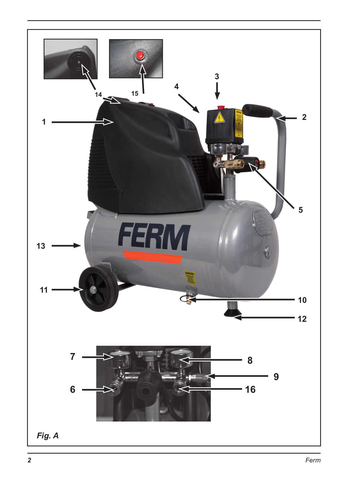
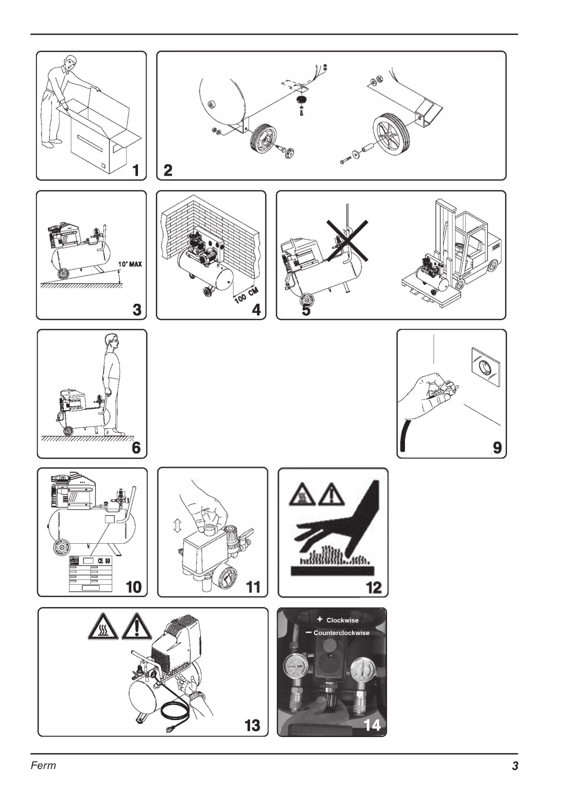
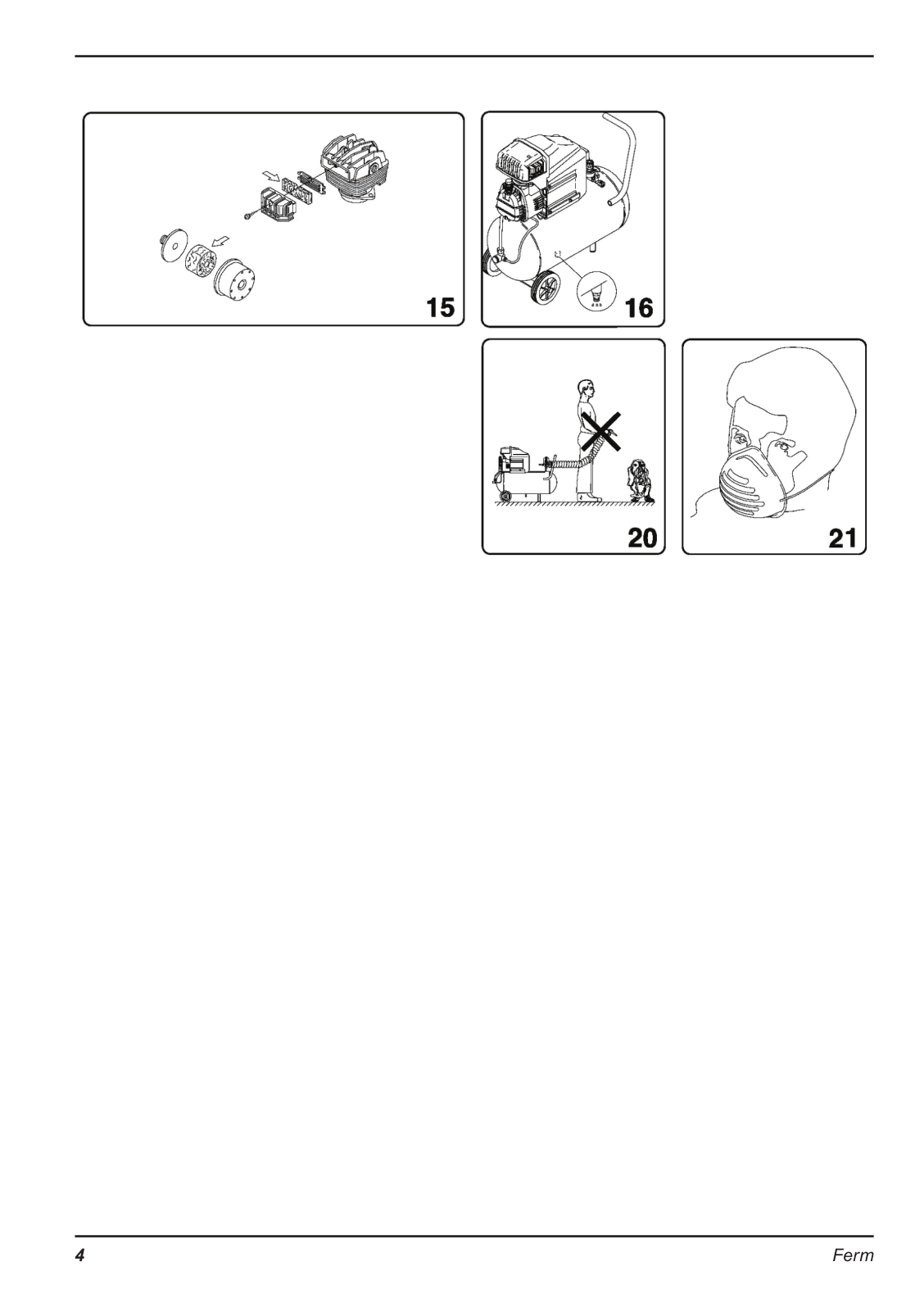
FERM
Loading...
B
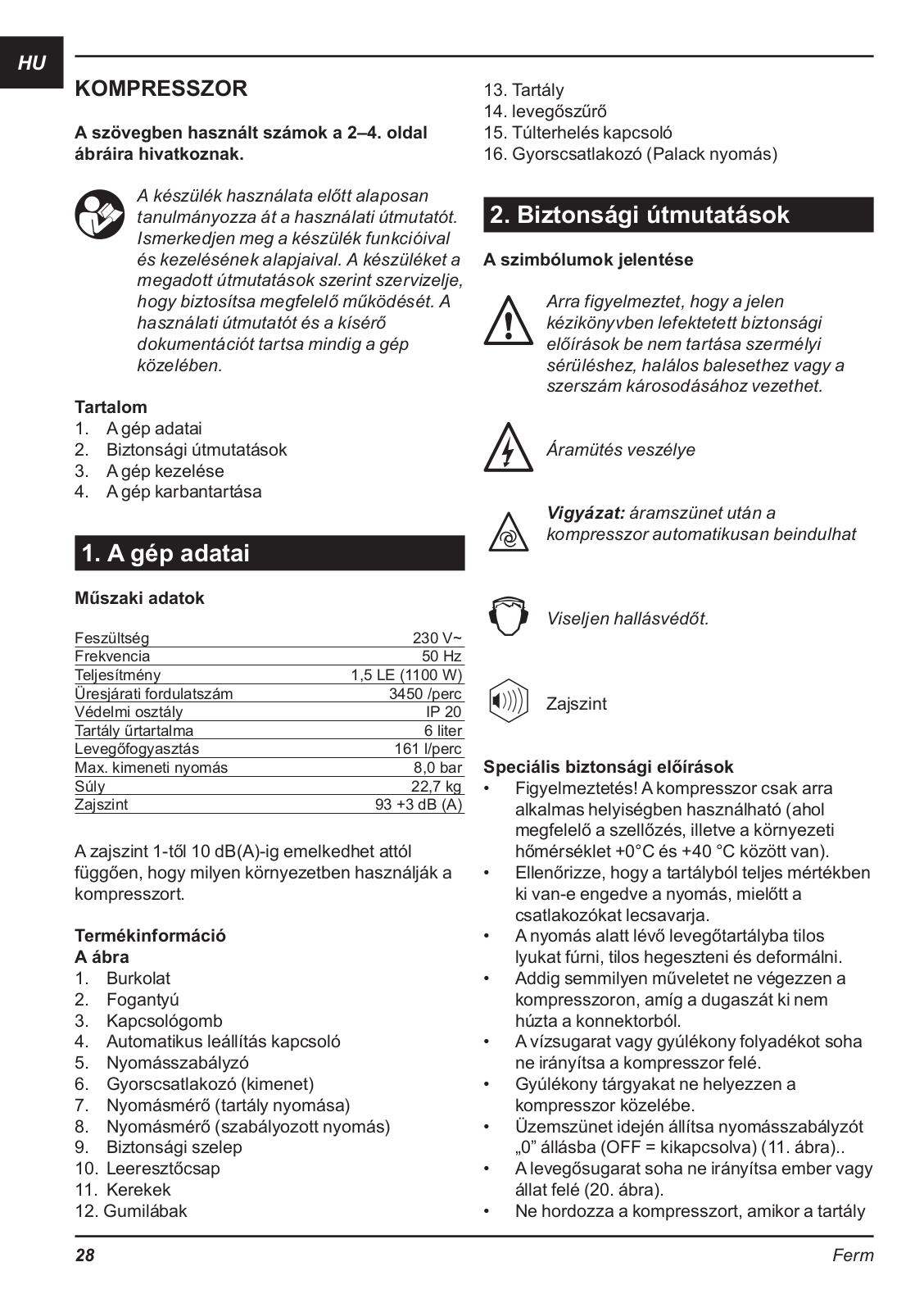
BCM1018
BCM1021
BGM10
BGM1003
2
BGM1019
BGM1020
2
BGM1021
2
BGM1022
BJM1009
4
BS-702
BSM1016
BSM1021
3
BSM1024
BZ-110
C
CDM1040
CDM1062
CDM1068
CDM1071
CDM1094
CDM1096
CDM1097
CDM1098
CDM1101
CDM1108S
CDM1112S
3
CDM1113S
3
CDM1114S
3
CDM1118
CDM1119
3
CDM1120
CDM1127
3
CDM1132
CDM1134
CDM1138
CDM1141P
CDM1142P
CDM1147P
COM1007P
CONCEPT 1500
CRM1024
CRM1028
CRM103
CRM1030
CRM1031
2
CRM1032
CRM1033
CRM1034
CRM1036
CRM1037
2
CRM1041
CRM1042
2
CRM1045
CRM1049
2
CSM1026
CSM1033
CSM1038
3
CSM1039
4
CSM1043
CTM1004
CTM1010
3
CTM1012
CTM1016
CTM1017
D
DHM-1100
2
DHM-1100C
DHM-1600
DSM1009
3
E
EBF-850K
EFM1001
2
ESM1009
ESM1010
ESM1015
ETM1002
ETM1003
2
F
FAG-125/1050
FAG-180
FAG-230
2
FAG-230/2000
FAG-230/2000K
FAS-1800K2
FBF-1050E
FBF-1200
FBF-6E
FBH-1100K
FBH-1100KD
FBH-620
FBH-850K
2
FBH-850KN
FBJ-710P
FBM-370
FBS-400
FBS-700
FBS-950
FBS-950N
FBSM-150
FBSM-150/50N
FBSM-50
FC-650F
2
FC-700
FC 730
Loading...
Loading...
Nothing found
CRM1042
User guide [ml]
40 pgs
9.52 Mb
0
User Manual [nl]
36 pgs
9.04 Mb
1
Table of contents
Loading...
FERM CRM1042 User Manual [nl]
...
FERM User Manual [nl]
Download
Specifications and Main Features
Frequently Asked Questions
User Manual
Download
Loading...
+
hidden pages
Unhide
You need points to download manuals.
1 point = 1 manual.
You can buy points or you can get point for every manual you upload.
Buy points
Upload your manuals
 Loading...