

Page 1
Ferm b.v. ● P.O. Box 134 ● 8280 AC Genemuiden-NL 9812/11
Ferm BS-702
Belt sander
Bandschleifmaschine
Bandschuurmachine
Ponceuse à bande
Máquina lijadora de cinta
Levigatrice a nastro
Bandslipmaskin
Penkkinauhahiomakone
Båndslipemaskin
Båndslibemaskine
Kézi szalagcsiszoló gép
Korongcsiszoló tartozékkal
Art.nr. 330702
USER’S MANUAL
GEBRAUCHSANLEITUNG
GEBRUIKSAANWIJZING
MODE D’EMPLOI
MODEO DE EMPLEO
ISTRUZIONI PER L'USO
BRUKSANVISNING
KÄYTTÖOHJE
BRUKSANVISNING
BRUGER VEJLEDNING
HASZNÁLATI UTASÍTÁS
Page 2
Ferm 35
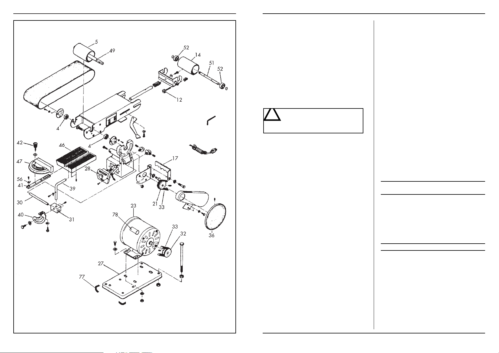
AVAILABLE SPARE PARTS FOR BS-702
REF.NR. DESCRIPTION FERM NR. BS-702
4 BALL BEARING 6201 ZZ 806201
5 DRIVE ROLLER 402800
12 ADJUSTMENT BOLT 402801
14 IDLER ROLLER 402802
17 PLATE TABLE 402803
21 DRIVE PULLEY 402804
23 MOTOR 402805
27 BASE PLATE 402806
28 SWITCH 402807
30 BAR 402809
31 ADJUSTMENT BLOCK 402810
32 MOTOR PULLEY 402811
33 V-BELT M21 402812
36 ALUMINIUM DISC 402815
39 TABLE BRACKET 402816
40 TABLE TILT TRUNION 402817
41 MITRE BAR 402818
42 KNOB/BOLT FOR MITRE BAR 402819
46 TABLE 402820
47 MITRE GAUGE 402821
49 SHAFT FOR DRIVE ROLLER 402822
51 SHAFT FOR IDLER ROLLER 402823
52 BALL BEARING 6201 ZZ 806201
56 INDICATOR 402824
78 CAPACITOR (6 µF = 450 VAC) 402825
77 RUBBER FOOT 402826
2 Ferm
Product: Ferm Belt sander
Type BS-702, Article number 330702
Ferm, Genemuiden, The Netherlands
Sound pressure level L
pa
80 dB(A)
SERIAL NUMBER
The serial number on the machine consists of the following elements.
Serial nr.
READ THIS MANUAL CAREFULLY BEFORE USING
THE BELT SANDER!
1. SPECIFIC SAFETY RULES
BEFORE USING THE MACHINE:
1. The following points need to be checked:
- Do the connecting voltage of the machine correspond with the mains voltage;
- Are the mains lead and the mains plug in a good
condition; strong, without ravels or damages.
2. For functional reasons the turning parts of this machine are not covered. Therefore it is of utmost importance to be careful. Hold the workpiece firmly, to
prevent it from slipping from your hands. Never
touch the sanding surfaces of a working machine with
your hands.
3. Avoid the use of long extension cables.
4. If necessary, secure the sanding machine with screws.
BEFORE YOU OPERATE THE MACHINE:
1. Always keep the mains cable away from moving parts
of the machine;
2. Use safety goggles;
3. Use a dust mask.
IMMEDIATELY SWITCH OF THE MACHINE
IN CASE OF:
1. defective mains plug, mains line or damage to the
mains line;
2. defective switch;
3. smoke or bad smell caused by scorched isulation.
2. INSTALLATION
Avoid the use of long extension cables. If necessary, secure the sanding machine on a working bench with help of
screws through the holes in the feet of the machine frame. Do not forget to leave enough space around the machine for the workpieces to be sanded.
3. DESCRIPTION
This machine combines all the advantages of a horizontal
and a vertical belt sander with those of a disc sander. Its
sturdy construction in cast iron and steel makes the machine suitable for every sanding job.
4. BEFORE PUTTING THE MACHINE
INTO OPERATION
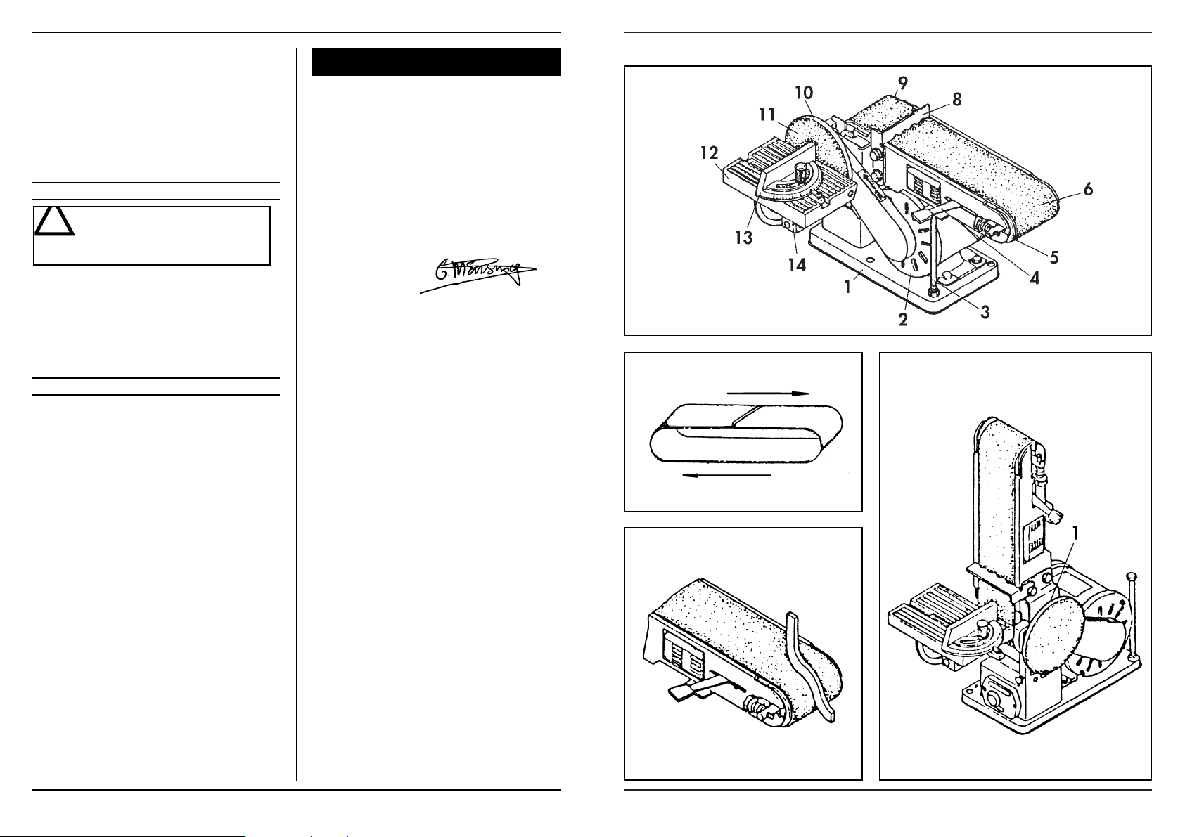
OPERATION (SEE FIG. 1)
1. Machine frame;
2. Motor;
3. Roller stop and parallel stop;
4. Clamping handle;
5. Transport roller;
6. Sanding belt;
8. Fence;
9. Drive roller;
10. Aluminium disc;
11. Sanding disc;
12. Work plate;
13. Mitre scale;
14. Supporting arm.
ASSEMBLY
- Put the machine frame on its head and press the four
rubber stops into the foot of the frame.
- Machine frame, aluminium disc (10) and work plate
(12) are supplied in separate packaging.
- Push the aluminium disc on the shaft and fasten the
ORDER NUMBER/YEAR OF CONSTRUCTION
GB
English
230 V~
50 Hz
375 W
1'
n0= 1450/min (disc)
V0 = 275 m/min (belt)
1'
150 mm
100 x 915 mm
Page 3
34 Ferm
EXPLODED VIEW
Ferm 3
disc with the socket bolt in the side of the disc.
- Place the work plate (12) with the shaft in the machine frame and secure the work plate with the bolt in
the side of the machine frame. Check with a 90° sash
angle on the work plate and against the sanding disc if
the angle is exactly 90°.
- If necessary, adjust this angle with the calibration indicator.
- The mitre scale (13), which is also supplied separately, can be placed on the work plate (13). With the use
of this mitre scale the angle of grinding can be determined precisely.
- The fence (8) for the belt sander can be placed behind
the uppermost bolt of the V-belt guard. In this way
the workpiece can be held firmly against the belt, without great hazards.
To prevent the workpiece or your fingers from getting caught between the work plate
(12) and the sanding disc (11), the space between work plate (12) and sanding disc (11)
must not exceed 1.6 mm.
THE CHOICE OF SANDING PAPER
With coarse sanding paper (P 50) generally most of
the material can be removed, and fine sanding paper
(P 120) is then used for finishing. An uneven surface is
first treated with coarse sanding paper and sanded
until it is even. Subsequently medium-coarse sanding
paper (P 80) is used to remove the scratches caused
by the first type of paper used. Fine sanding paper (P
120) is used for finishing. The sanding needs to be continued until the surface is smooth.
THE PLACING OF THE SANDING PAPER (SEE
FIG. 2)
When the sanding machine is held with the sanding
disc turned towards you, the sanding belt moves from
right to left along the upper part of the machine. Because of this turning direction the workpiece will be
pressed against the right side of the fence. An arrow
on the inside indicates the right direction of running
of the sanding belt (see drawing). If no direction is indicated, the sanding belt must be placed in such a way
that the elevated part of the seam is placed into the
turning direction of the belt. So it is very important
that the sanding belt is placed in the correct way. The
machine uses standard 100 x 915 mm sanding belts
(nr 7):
- Remove the plug from the mains socket;
- Push the clamping handle completely to the right
to take away the tension of the transport rollers;
- Push the sanding belt along both of the transport
rollers, starting from the back of the machine;
-
Push the clamping handle completely to the left.
Now the sanding belt should be completely tight.
- Turn the transport roller exactly in a right angle to
the direction of the sanding belts with the use of
the winged nut at the right roller. The direction of
running of the belt is adjusted correctly if the sides
of the sanding belt are running parallel to the bearing plate.
THE SANDING DISC
Paper or “velcro” plates are used for the sanding disc.
The standard diameter is 150 mm. The plates are self
adhesive.
VERTICAL PLACING OF THE SANDING BELT
(SEE FIG. 4)
For more flexibility of the sanding belt its bottom side
can be used, because there is no bearing plate. For an
easy reach of this bottom side the sanding belt can be
placed in vertical position:
- Loosen the two nuts (1) at the front of the sanding
machine, around the left transport roller shaft,
with the use of an open-end spanner;
- Push the sanding belt up in the position desired;
- Fasten the two nuts (1) again;
- The workpiece can now rest on the worktop instead of on the sanding belt;
- The work plate which is used for the sanding disc
can now be pushed with the shaft into the hole of
the machine frame, at the left side of the sanding
machine;
- Fasten the bolt at the back of the machine;
- The work plate can now be used as support for
the sanding of the work piece against the sanding
belt.
5. PUTTING THE MACHINE INTO
OPERATION
- Press the switch into position ‘1’ to put your sanding
machine into operation.
- To switch off the machine the same switch needs to
be pressed to position ‘0’.
- Always keep the mains cable away from moving parts.
- There is no need to apply any pressure with the
workpiece, because this only slows down the speed
of the sanding disc.
6. SANDING OPERATION
The sanding belt and disc supplied with this sanding machine are suitable for the sanding of metal, wood or synthetic surfaces. The workpiece should always be held
firmly during sanding. No extra pressure is needed. Guide the work piece up and down over the sanding belt, in
order to prevent the sanding belt and plate from wearing
through in one place. Round objects can be sanded at the
ends of the sanding belt (see Fig. 3). Work pieces which
are longer than the sanding machine can be sanded by removing the fence.
NB: To prevent splintering, wood always needs to be
sanded in the longitudinal direction of the grain.
!
Page 4
Ferm 33
Fig. 1
Fig. 2
Fig. 4
Fig. 3
To treat a very soft surface, there is a very handy method
to ‘bring the particles to the surface’. This is done as follows: wet the already sanded surface with a cloth or
sponge and let it dry well. Some wood fibres will swell up
more than others, which leads to a rougher surface than
before. Now the higher particles are treated with fine
sanding paper, the result is a remarkably smooth surface.
This method should not be applied with varnished wood,
however, because the varnish may come loose because
of the moisture.
7. MAINTENANCE
While maintaining and cleaning the machine pull the plug from the mainssocket. Never
use water or other agressive liquids to clean
the machine. Clean the machine by brushing
it with a brush.
PERIODIC MAINTANCE OF THE BELT SANDER
WILL PREVENT UNNECESSARY PROBLEMS!
1. Keep the ventilation slots of the machine clean to
prevent overheating of the motor.
2. There is no need to lubricate the transport rollers of
the machine.
8. MALFUNCTION
Below we have listed a number of possible causes and
corresponding solutions in case the machine does not
function as it should:
1. The electromotor gets hot.
The cool ventilation slots in the motor are stopped up
with dirt:
- clean the cool ventilation slots.
The motor is defective:
- Have your sanding machine repaired or checked at
your local Ferm dealer.
2. The connected machine does not work.
Interruption in the mains connection:
- Check mains connection for fracture;
- Have your sanding machine repaired/checked at your
local Ferm dealer.
ClEl
■
DECLARATION OF CONFORMITY
(
GB
)
We declare under our sole responsability that this
product is in conformity with the following
standards or standardized documents
EN61029-1
EN55014, EN61000-3-2, EN61000-3-3, EN55104
in accordance with the regulations:
89/392/EEC
73/23/EEC
89/336/EEC
from 26-05-1998
GENEMUIDEN NL
G.M. Ensing
Quality department
4 Ferm
!
Page 5
32 Ferm
Produkt: Ferm Bandschleifmaschine
Typ BS-702, Artikelnummer 330702;
Ferm, Genemuiden, Niederlande
Schalldruckpegel L
pa
80 dB(A)
SERIENNUMMER
Die Seriennummer auf dem Gerät setzt sich folgendermaßen zusammen:
Serial nr.
LESEN SIE BITTE VOR INBETRIEBNAHME
DIESE BETRIEBSANLEITUNG GRÜNDLICH
DURCH!
1. SPEZIELLE SICHERHEITSVORSCHRIFTEN
BEVOR INGEBRAUCHNAHME DER MASCHINE:
1. Kontrollieren Sie folgendes:
- Ist die Netzspannung änlich an der Spannung
erwäht auf die Typ-platte der Maschine ;
- Sind die Stecker, das Schnur und die Steckdose in
gutem Zustande;
2. Die rotierenden Teile des Gerätes sind aus funktionellen Gründen nicht abgedeckt. Seien Sie darum
vorsichtig. Halten Sie das Werkstück gut fest, damit
es nicht aus Ihren Händen rutscht, wodurch sie in
Berührung mit dem Schleifband kommen könnten.
3. Vermeiden Sie das Gebrauch von zu lange Verlengungskäbel.
4. Befestigen Sie die Schleifmaschine gegebenenfalls mit
Schrauben.
BEIM INBETRIEBSTELLUNG DER MASCHINE:
1. Achten Sie darauf, daß das Netzkabel nicht in Berührung mit bewegenden Teilen des Gerätes kommt.
2. Benutzen Sie eine Schutzbrille.
3. Benutzen Sie ein Atemschutzfilter.
DAS GERÄT SOFORT AUSSCHALTEN BEI:
1. defektem Netzstecker, Netzkabel oder Kabelschaden;
2. defektem Schalter;
3. Rauch oder Geruch nach verbranntem Isoliermaterial.
2. INSTALLATION
Vermeiden Sie den Gebrauch von zu langen Verlängerungsschnuren. Befestigen Sie die Schleifmaschine eventuell mit Hilfe von Schrauben durch die Löcher in den
Füßen des Maschinegestells. Achten Sie darauf, daß Sie im
Maschinenbereich genügend Platz für die zu schleifenden
Werkstücke haben.
3. BESCHREIBUNG
Diese Schleifmaschine ist ein kombiniertes Gerät mit allen Vorteilen einer horizontalen und vertikalen Bandschleifmaschine und einer Scheibenschleifmaschine. Durch
die robuste Ausführung in Gußeisen und Stahl, ist diese
Maschine für alle Schleifarbeiten geeignet.
4. BEVOR INBETRIEBNAHME
ANWENDUNG (SIEHE FIG. 1)
1. Maschinengestell;
2. Motor;
3. Schienen- und Parallelanschlag;
4. Spannhebel;
5. Laufrolle;
6. Schleifband;
8. Längsschiene;
9. Antriebsrolle;
10. Aluminiumscheibe;
11. Schleifscheibe;
12. Arbeitsplatte;
13. Gehrungsskala;
14. Tragarm.
MONTAGE
- Stellen Sie das Maschinengestell mit der Unterseite
nach oben, und befestigen Sie die vier Gummifüße auf
dem Fuß (1) des Maschinengestelles.
- Maschinengestell, Aluminiumscheibe (10) und Arbeitsplatte (12) werden getrennt verpackt geliefert.
- Schieben Sie die Aluminiumscheibe (10) auf die Achse und befestigen Sie die Scheibe mit der Sechskantschraube an der Seite der Scheibe.
- Legen Sie die Arbeitsplatte (12) mit der Achse in das
Maschinengestell und befestigen Sie die Arbeitsplatte
mit der Schraube an der Seite des Maschinengestelles.
- Kontrollieren Sie mit einem 90° Winkelmesser auf
der Arbeitsplatte, gegen die Schleifscheibe, ob der
Winkel genau 90° beträgt.
- Stellen Sie diesen Winkel gegebenenfalls ein, indem
Sie den Pfeil auf der Skala verstellen.
- Die Gehrungsskala (130), die auch einzeln lieferbar
ist, kann auf der Arbeitsplatte (12) angebracht werden. Mit Hilfe der Gehrungsskala (13) kann der Winkel, in dem Sie schleifen wollen genau eingestellt werden.
- Die Längsschiene (8) für die Bandschleifmaschine
kann hinter der obersten Schraube des Keilriemenschutzgehäuses angebracht werden. Auf diese Art
und Weise kann das Werkstück fest und ohne große
Gefahren gegen das Schleifband gehalten werden.
Um zu verhindern, daß das Werkstück oder
Ihre Finger zwischen die Arbeitsplatte (12)
und die Schleifscheibe (13) geraten, muß der
Abstand zwischen Arbeitsplatte (12) und
Schleifscheibe (13) maximal 1,6 mm betragen.
!
ORDERNUMMER/BAUJAHR
Deutsch
D
Ferm 5
Page 6

Ferm 31
WAHL DES SCHLEIFPAPIERS
Grobes Schleifpapier (Körnung 50) entfernt im allgemeinen das meiste Material und feines Schleifpapier
(Körnung 120) kann für die Endbearbeitung benutzt
werden. Wenn die Oberfläche uneben ist, beginnen
Sie mit grobem Schleifpapier und schleifen, bis sie
glatt ist. Anschließend verwenden Sie mittelgrobes
Schleifpapier (Körnung 80), um die Kratzer, die das
erste Papier verursacht hat, zu entfernen. Für die
Endbearbeitung nehmen Sie das feine Schleifpapier
(Körnung 120). Schleifen Sie solange bis die
Oberfläche glatt ist.
DAS ANBRINGEN DES SCHLEIFPAPIERS
(SIEHE FIG. 2)
Wenn Sie die Schleifmaschine so aufstellen, daß die
Schleifscheibe Ihnen zugewendet ist, bewegt sich das
Schleifband von rechts nach links über die Oberseite
der Maschine. Durch diese Drehrichtung wird das
Werkstück gegen die rechte Seite der Längsschiene
gedrückt. Die richtige Laufrichtung des Schleifbandes
ist mit einem Pfeil an der Innenseite angegeben (siehe
Zeichnung). Ist kein Pfeil eingezeichnet worden muß
das Schleifband so angebracht werden, daß der
erhöhte Teil der Naht in Drehrichtung steht. Achten
sie also darauf, daß das Schleifband auf die richtige Art
und Weise angebracht wird. Verwenden Sie für die
Maschine Standardschleifbänder (Nr. 7) 100 x 915
mm.
- Ziehen Sie den Netzstecker aus der Steckdose.
- Drücken Sie den Spannhebel ganz nach rechts, um
die Laufrollen zu entspannen.
- Schieben Sie von der Rückseite der Maschine aus
die Schleifbänder über die Laufrollen.
- Drücken Sie den Spannhebel ganz nach links. Das
Schleifband spannt sich nun über die Laufrollen.
- Drehen Sie mit der Flügelmutter an der rechten
Laufrolle die Laufrolle genau im rechten Winkel
zum Lauf der Schleifbänder. Der Bandlauf ist richtig eingestellt, wenn die Seiten der Schleifbänder
parallel zur Unterlegplatte laufen.
DIE SCHLEIFSCHEIBE
Verwenden Sie für die Schleifscheibe Papier oder
Stoffrollen mit einem Standarddurchmesser von 150
mm. Die Scheiben sind selbstklebend.
DAS VERTIKALE ANBRINGEN DER
SCHLEIFBÄNDER (SIEHE FIG. 4)
Für eine größere Flexibilität des Schleifbandes kann
die Unterseite des Schleifbandes verwendet werden,
weil sich hier keine Unterlegplatte befindet. Um einfacher an die Unterseite zu gelangen, können Sie das
Schleifband vertikal anbringen.
- Drehen Sie mit dem Steckschlüssel die zwei Muttern (1) bei der linken Laufrollenachse an der Vorderseite der Schleifmaschine los.
- Drehen Sie das Schleifband nach oben in die
gewünschte Position.
- Drehen Sie die beiden Muttern (1) wieder fest.
- Das Werkstück kann nun, anstatt auf dem Schleifband, auf der Arbeitsplatte ruhen.
- Die Arbeitsplatte, die für die Schleifscheibe gebraucht wird, kann nun an der linken Seite der
Schleifmaschine mit Hilfe der Achse in das Loch
des Maschinengestelles gesteckt werden.
- Drehen Sie die Schraube an der Rückseite der
Schleifmaschine fest.
- Sie können die Arbeitsplatte nun als Stütze zum
Schleifen des Werkstückes am Schleifband benutzen.
5. INBETRIEBNAHME
- Drücken Sie den Schalter in Stand ‘1’ um die Schleifmaschine in Betrieb zu nehmen.
- Um die Maschine auszuschalten, bringen Sie denselben Schalter in Stand ‘0’.
- Halten Sie das Netzkabel fern von bewegenden Teilen.
- Üben Sie keinen großen Druck mit dem Werkstück
aus, damit verlangsamen Sie das Schleifband nur.
6. DAS SCHLEIFEN
Die bei dieser Schleifmaschine mitgelieferte Schleifplatte
und das mitgelieferte Schleifband eignen sich zum Schleifen von Metall, Holz oder Kunststoff. Halten Sie das
Werkstück während des Schleifens gut fest. Üben Sie keinen großen Druck aus. Bewegen Sie das Werkstück über
das Schleifband und die Schleifplatte hin und her, um zu
verhindern, daß Schleifband und Schleifplatte an einer
Stelle verschleißen. Runde Gegenstände können mit den
äußeren Enden des Schleifbandes geschliffen werden
(siehe Fig. 3). Werkstücke, die länger als die Schleifmaschine sind, können geschliffen werden, indem die Längsschiene entfernt wird.
N.B.: Schleifen Sie Holz immer in Richtung der Holzmaserung, um Absplittern zu verhindern.
Um sehr weiche Oberflächen zu bearbeiten, können Sie
den Trick “Fasern nach oben bringen” anwenden. Das
geht folgendermaßen: Befeuchten Sie die geschliffenen
Oberflächen mit einem nassem Tuch oder Schwamm
und lassen Sie alles wieder gut trocknen. Manche Holzfasern schwellen nun mehr als andere, so daß die
Oberfläche schließlich grober ist als vorher. Schleifen Sie
nun mit feinem Schleifpapier alle herausragenden Teile
ab, und Sie erhalten eine sichtbar glattere Oberfläche.
Wenden Sie diese Methode allerdings nicht bei gelacktem Holz an. Der Lack kann sich durch die Feuchtigkeit
lösen.
6 Ferm
Page 7

30 Ferm
7. WARTUNG
Beim sauberhalten der Maschine den Stecker aus der Steckdose entfernen. Nie Wasser
oder beissende Flüssigkeiten benützen für
das Saubermachen der Maschine. Bürsten
Sie die Maschine sauber mit einer Bürste.
REGELMÄßIGE WARTUNG DER BANDSCHLEIFMASCHINE BEUGT PROBLEME VOR!
1. Halten Sie die Lüftungsschlitze der Maschine sauber,
um ein Überhitzung des Motors zu verhindern.
2. Die Laufrollen der Maschine brauchen nicht geschmiert zu werden.
8. STÖRUNGEN
Im Fall daß das Gerät nicht gut funktioniert, geben wir
jetzt einige mögliche Ursachen und Lösungen:
1. Erhitzen des Motors.
Die Entlüftungsschlitze sind verstopft mit Schmutz:
- Saubern Sie die Entlüftungsschlitze.
Der Motor ist defekt:
- Bieten Sie das Gerät zur Reperation an bei Ihren Ferm
Dealer.
2. Das eingeschaltete Gerät funktioniert nicht
Bruch im Netzanschluß:
- Kontollieren Sie die Netzanschluß;
- Bieten Sie das Gerät zur Reparation an bei Ihren Ferm
Dealer.
ClEl
■
KONFORMITÄTSERKLÄRUNG
(D)
Wir erklären in alleiniger Verantwortung, daß
dieses Produkt mit den folgende Normen oder
normativen Dokumenten übereinstimmt:
EN61029-1
EN55014, EN61000-3-2, EN61000-3-3, EN55104
gemaß den Bestimmungen der Richtlinien:
89/392/EWG
73/23/EWG
89/336/EWG
ab 26-05-1998
GENEMUIDEN NL
G.M. Ensing
Quality department
Produkt: Ferm bandschuurmachine.
Type BS-702,, artikelnummer 330702;
Ferm, Genemuiden, Nederland
Geluidsdrukniveau L
pa
80 dB(A)
SERIE NUMMER
Het serienummer op de machine komt als volgt tot stand.
Serial nr.
LEES DEZE GEBRUIKSAANWIJZING GOED
DOOR, VOORDAT U DE BANDSCHUURMACHINE INGEBRUIK NEEMT!
1. SPECIALE VEILIGHEIDSVOORSCHRIFTEN
BIJ HET INGEBRUIKNEMEN VAN DE MACHINE:
1. Controleer het volgende:
- komt de aansluitspanning van de schuurmachine
met de netspanning overeen;
- wordt een geaarde netaansluiting gebruikt;
- zijn het netsnoer en de netstekker in goede staat:
stevig, zonder rafels of beschadigingen.
2. Om functionele redenen zijn de draaiende delen van
dit werktuig niet bedekt. Wees daarom voorzichtig.
Houdt het werkstuk stevig vast, zodat het niet uit uw
handen schiet waardoor deze in aanraking kunnen
komen met de schuurvlakken.
3. Vermijd het gebruik van lange verlengkabels.
4. Zet de schuurmachine eventueel vast met schroeven.
BIJ HET IN BEDRIJFSTELLEN VAN DE MACHINE:
1. Houd het netsnoer altijd uit de buurt van bewegende
delen van het gereedschap.
2. Gebruik een veiligheidsbril.
3. Gebruik een stofmasker.
DE MACHINE ONMIDDELLIJK UITZETTEN BIJ:
1. storing in de netstekker, netsnoer of snoerbeschadiging;
2. defecte schakelaar;
3. rook of stank van verschroeide isolatie.
2. INSTALLATIE
Vermijd het gebruik van lange verlengkabels. Zet de
schuurmachine eventueel op een werkbank vast met behulp van schroeven door de gaten in de voeten van het machineframe. Let op dat er voldoende ruimte rondom de
machine is voor de te schuren werkstukken.
ORDERNUMMER/BOUWJAAR
Nederlands
NL
!
Ferm 7
Page 8

ség következtében leválhat, és tönkreteheti a csiszolóanyagot is.
7. KARBANTARTÁS
A karbantartás és tisztítás során mindig
húzza ki a hálózati csatlakozót a dugós
kapcsolóaljzatból. A készülék elektromos részeinek tisztításához soha ne
használjon vizet vagy más folyadékot.
A RENDSZERES KARBANTARTÁS MEGELÕZI A
SZÜKSÉGTELEN PROBLÉMÁKAT!
1. Tartsa tisztán a gép szellőzőnyílásait, hogy elkerülje a motor túlmelegedését.
2. A gép vezető hengereit nem kell olajozni.
8. HIBÁK MEGKERÉSE ÉS MEGOLDÁSA
Amennyiben a csiszológép nem megfelelően üzemel, az alábbiakban felsorolunk néhány lehetséges
hibaokot és a hozzájuk tartozó megoldásokat:
1. Az elektromotor túlmelegszik.
A motor szellőzőnyílásai eldugultak a szennyeződéstől:
- Tisztítsa meg a szellőnyílásokat.
Elromlott a motor.
- Javíttassa meg a készüléket a Ferm árusító
helyen
2. A bekapcsolt gép nem működik.
Szakadás a hálózati csatlakozóban:
- Ellenőrizze, hogy a hálózati csatlakozók nem
hibásak-e.
- Javíttassa meg a készüléket a Ferm árusító
helyen.
ClEl
n
MEGFELELŐSÉG IGAZOLÁSA
(H)
Igazoljuk, hogy ez a termék eleget tesz a
következő szabványoknak, illetve műszaki
dokumentumoknak:
EN61029-1
EN55014, EN61000-3-2, EN61000-3-3, EN55104
megegyezik a következő műszaki irányvonalak
előírásaival:
89/392/EEC
73/23/EEC
89/336/EEC
1998-05-26-tól
GENEMUIDEN NL
G.M. Ensing
minőségellenőrző
osztály
!
Ferm 29
3. BESCHRIJVING
De schuurmachine is een gecombineerde machine met
alle voordelen van een horizontale en verticale bandschuurmachine en die van een schijfschuurmachine.
Door de robuuste uitvoering in gietijzer en staal is deze
machine geschikt voor alle schuurwerkzaamheden.
4. VOOR INBEDRIJFSTELLING
BEDIENING (ZIE FIG.1)
1. Machineframe;
2. Motor;
3. Geleider- en parallelaanslag;
4. Spanhendel;
5. Geleiderol;
6. Schuurband;
8. Langsgeleider;
9. Aandrijfrol;
10. Aluminium schijf;
11. Schuurschijf;
12. Werkblad;
13. Verstekschaal;
14. Draagarm.
MONTAGE
- Zet het machineframe op de kop en druk de vier rubber voetjes in de voet (1) van het machineframe.
- Machineframe, aluminium schijf (10) en werkblad
(12), worden afzonderlijk verpakt geleverd.
- Schuif de aluminium schijf (10) op de as en zet de schijf
vast met de inbusbout in de zijkant van de schijf.
- Plaats het werkblad (12) met de as in het machineframe en zet het werkblad vast m.b.v. de bout in de zijkant van het machineframe. Controleer met een 90°
blokhaak op het werkblad en tegen de schuurschijf of
de hoek precies 90° is.
- Stel deze hoek eventueel in door het wijzertje van de
schaalverdeling te verdraaien.
- Op het werkblad (12) kan de verstekschaal (13) geplaatst worden die ook los bijgeleverd wordt. M.b.v.
deze verstekschaal (13) kan de hoek waarmee geslepen wordt precies worden ingesteld.
- De langsgeleider (8) voor de bandschuurmachine kan
achter de bovenste bout geplaatst worden van de Vriem afschermkast. Op deze wijze kan een werkstuk
stevig en zonder grote gevaren tegen de schuurband
gehouden worden.
Om te voorkomen dat het werkstuk of uw
vingers tussen het werkblad (12) en de
schuurschijf (11) kunnen komen, moet de afstand tussen werkblad (12) en schuurschijf
(11) maximaal 1,6 mm zijn.
KEUZE VAN HET SCHUURPAPIER
Grof schuurpapier (korrel 50) verwijdert over het algemeen het meeste materiaal en fijn schuurpapier
(korrel 120) wordt gebruikt voor de afwerking. Als
het oppervlak oneffen is, begint u met grof schuurpapier en schuurt totdat het vlak is. Vervolgens gebruikt
u middelgrof schuurpapier (korrel 80) om de krassen
die het eerste papier heeft achtergelaten te verwijderen en tenslotte neemt u fijn schuurpapier (korrel
120) voor de afwerking. Ga door met schuren totdat
het oppervlak glad is.
SCHUURPAPIER AANBRENGEN (ZIE FIG.2)
Wanneer u de schuurmachine met de schuurschijf
naar u toegekeerd heeft staan, beweegt de schuurband van rechts naar links over de bovenzijde van de
machine. Door deze draairichting zal het werkstuk
tegen de rechterzijde van de langsgeleider gedrukt
worden. De juiste looprichting van de schuurband
staat aan de binnenzijde aangegeven d.m.v. een pijl
(zie tekening). Wanneer geen pijl is aangegeven, moet
de schuurband zo geplaatst worden dat het verhoogde gedeelte van de naad, in de draairichting van de
band staat. Let op dat de schuurband dus op de juiste
wijze wordt geplaatst. De machine gebruikt standaard 100 x 915 mm schuurbanden (nr.7).
- Trek de netstekker uit het stopcontact (de wandcontactdoos);
- Druk de spanhendel geheel naar rechts om de spanning van de geleiderollen te halen.
- Schuif vanaf de achterkant van de machine de schuurband over de beide geleiderollen.
- Druk de spanhendel geheel naar links. De schuurband moet nu strak over de geleiderollen.
- Draai m.b.v. de vleugelmoer aan de rechter geleiderol de geleiderol precies haaks op de loop van de
schuurbanden. De bandloop is juist ingesteld wanneer de zijkanten van de schuurband evenwijdig lopen aan de onderlegplaat.
DE SCHUURSCHIJF
Voor de schuurschijf worden papier- of stofplaten gebruikt met een standaard diameter van 150 mm.
De schuurplaten zijn zelfklevend.
VERTICAAL PLAATSEN VAN DE SCHUURBAND (ZIE FIG. 4)
Voor een grotere flexibiliteit van de schuurband kan
de onderzijde van de schuurband gebruikt worden
omdat zich hier geen onderlegplaat bevind. Om deze
onderzijde makkelijk bereikbaar te maken, kan de
schuurband verticaal worden geplaatst.
- Draai de twee moeren (1) aan de voorzijde van de
schuurmachine, rond de linker geleiderrolas, los
m.b.v. een steeksleutel;
- Draai de schuurband omhoog in de gewenste positie;
- Draai de twee moeren (1) weer vast;
- Het werkstuk kan nu op de werktafel rusten en
niet op de schuurband;
- Het werkblad dat gebruikt wordt voor de slijpschijf kan nu aan de linkerzijde van de schuurmachine m.b.v. de as in het gat van het machineframe
!
8 Ferm
Page 9

Hogy elkerülje, hogy a munkadarab vagy
ujja a tárgyasztal (12) és a csiszolótárcsa
(11) közé kerüljön, a tárgyasztal (12) és a
csiszolótárcsa (11) közötti távolság ne
legyen több 1,6 mm-nél.
A CSISZOLÓPAPÍR KIVÁLASZTÁSA
A durva csiszolópapír (50-es szemcse) általában a
legtöbb anyagot eltávolítja, a befejezéshez pedig a
finom csiszolópapír (120-as szemcse) használható. Ha a felszín egyenetlen, kezdje a munkát a
durva csiszolópapírral, és addig folytassa, amíg
egyenletessé nem válik. Ezután használjon közepesen durva papírt (80-as szemcse), hogy az első
papír után ottmaradt karcokat eltávolítsa, végül finom csiszolópapírral (120-as szemcse) fejezze be
a munkát. Addig folytassa a csiszolást, amíg a
felszín teljesen sima nem lesz.
A CSISZOLÓPAPÍR FELHELYEZÉSE
(LÁSD A 2. ÁBRÁT)
A csiszológépet és a csiszolótárcsát maga felé
fordítva mozdítsa a csiszolószalagot jobbról balra a
gép felső részén. Ezzel a forgatási iránnyal a munkadarab a vezető jobb oldalához nyomódik. A csiszolószalag megfelelő irányú mozgását nyíl mutatja
a belső oldalon (lásd az ábrát). Ahol nem szerepel
nyíl, a csiszolópapírt úgy kell felhelyezni, hogy az illesztés magasabb része a szalag forgási iránya felé
álljon. Ügyeljen tehát arra, hogy a csiszolószalagot
a megfelelő módon helyezze fel. A gép 100 x 915
mm-es csiszolószalaggal működik (7-es ábra).
- Húzza ki a csatlakozót a fali csatlakozóból.
- Tolja a feszítő kart egészen jobbra, hogy
megszűnjön a feszítő erő a vezető hengerekre.
- Csúsztassa a gép hátuljáról az új csiszolószalagot a két vezető hengerre.
- Tolja a feszítő kart egészen balra. A csiszolószalag ekkor a vezető hengerekre simul.
- Csavarja a szárnyas anya segítségével a jobb
oldali vezető hengert pontosan derékszögben a
csiszolófogak pályájára. A szalg futását akkor
állította be, amikor a csiszolószalag oldalai egyenletesen mozognak az alátétlapon.
A CSISZOLÓTÁRCSA
A csiszolótárcsához 150 mm átmérőjű papír- vagy
anyaglapokat kell használni.
A csiszolólapok öntapadóak.
A CSISZOLÓSZALAG FÜGGÕLEGES FELTÉTELE (LÁSD A 4. ÁBRÁT)
A csiszolószalag nagyobb rugalmassága érdekében használható a csiszolószalag alsó oldala, mert
itt nem található alátét lap. Hogy ez az alsó rész könnyen elérhető legyen, a csiszolószalagot függőlegesen lehet felhelyezni.
- Csavarja ki a két anyát (1) a csiszológép elején a
bal vezetőhenger körül egy villáskulcs
segítségével;
- Fordítsa a csiszolószalagot felfelé a kívánt helyzetbe;
- Csavarja be újra a két anyát (1);
- A munkadarab most a tárgyasztalon fekhet és
nem a csiszolószalagon;
- A köszörűtárcsához használt tárgyasztal most a
csiszológép baloldalára kerülhet, a tengely a
acélváz nyílásába történő átállításával;
- Csavarja be a rögzítő elemet a csiszológép
hátsó oldalán;
- A tárgyasztal most alátámaszthatja a csiszolást
a munkadarab a csiszolószalaghoz nyomásával.
5. ÜZEMBEHELYEZÉS
- A kapcsolót állítsa az "I"-es fokozatra a gép be-
kapcsolásához.
- A gép kikapcsolásához állítsa a kapcsolót a "0"
fokozatba.
- A hálózati zsinórt mindig tartsa távol a mozgó
részektől.
- Ne gyakoroljon túl nagy nyomóerőt a munka-
darabra, ez ugyanis csak a csiszolószalag
mozgását lassítja.
6. CSISZOLÁS
Az ehhez a csiszológéphez adott csiszolószalag és
–korong alkalmas fém, fa vagy műanyag megmunkálásához. A csiszolás során szilárdan, biztonságosan fogja a munkadarabot. Ne gyakoroljon
rá külön nyomóerőt.
Mozgassa a munkadarabot oda-vissza a csiszolószalagon és – korongon, hogy a csiszolószalag és
–korong ne egy ponton kopjon. Kerek tárgyak a
csiszolószalag végein csiszolhatók (lásd a 3-as
ábrát). A csiszológépnél hosszabb munkadarabokat a vezető eltávolításával csiszolhatunk.
Megj.: Fa csiszolásánál mindig az erezet hosszanti
irányában csiszoljon, hogy elkerülje a szálkásodást. Kivétel: olajmázolás alá, ekkor a jobb tapadás érdekében célszerű félkeresztbe csiszolni.
Különösen lágy felület megmunkálásakor hatásos
módszer alkalmazható a szemcsék felszínre hozatalához. Ez a következőképpen történik: Nedvesítse meg a már csiszolt felületet egy vizes ruhával vagy szivaccsal és hagyja alaposan megszáradni.
Némelyik farost jobban megduzzad, így a felszín
egyenetlenebb lesz, mint először (a nedvesség
felhúzza a szálát). Ekkor finom csiszolópapírral
csiszolja le a kiálló részeket és az eredmény meglepően sima felület lesz. Ezt a módszert azonban ne
használja lakkozott fa esetében. A lakk a nedves-
!
28 Ferm
worden gestoken;
- Draai de bout vast aan de achterzijde van de
schuurmachine;
- Het werkblad is nu te gebruiken als ondersteuning voor het schuren van het werkstuk tegen de
schuurband.
5. INBEDRIJFSTELLING
- Zet de schakelaar naar stand ‘1’ om uw schuurmachine in werking te stellen.
- Om uit te schakelen moet u dezelfde schakelaar naar
stand ‘0’ drukken.
- Houd het netsnoer altijd uit de buurt van bewegende
delen.
- Oefen geen grote druk uit met het werkstuk, dit vertraagd de schuurband alleen maar.
6. HET SCHUREN
De bij deze schuurmachine geleverde schuurband en plaat zijn geschikt voor het bewerken van metaal, hout of
kunststof. Houdt het werkstuk tijdens het schuren stevig
vast. Geen extra druk uitoefenen.
Beweeg het werkstuk heen en weer over de schuurband
en -plaat om te voorkomen dat op één plaats de schuurband en -plaat doorslijten. Ronde voorwerpen kunnen
aan de uiteinden van de schuurband geschuurd worden
(zie Fig. 3). Werkstukken die langer zijn dan de schuurmachine kunnen geschuurd worden door de langsgeleider
te verwijderen.
N.B.:Schuur bij hout altijd in de lengterichting van de
nerf om splintervorming te voorkomen.
Om een zeer zacht oppervlak te bewerken kan het trucje
worden toegepast om ‘de korrels boven te halen’. Dit
werkt als volgt: Maak het reeds geschuurde oppervlak nat
met een vochtige doek of spons en laat het grondig drogen. Sommige houtvezels zullen meer zwellen dan andere, zodat het oppervlak uiteindelijk ruwer is dan voorheen. Schuur nu met fijn schuurpapier de uitstekende
deeltjes weg en u krijgt een opmerkelijk glad oppervlak.
Gebruik deze methode echter niet op gevernist hout. De
vernis kan losraken door de vochtigheid.
7. ONDERHOUD
Bij onderhoud en schoonmaak altijd de netstekker uit het stopcontact (de wandcontactdoos) halen. Gebruik nooit water of andere vloeistoffen bij het schoonmaken van
de elektrische delen van de schuurmachine.
PERIODIEK ONDERHOUD AAN DE SCHUURMACHINE VOORKOMT ONNODIGE PROBLEMEN!
1. Houd de ventilatiesleuven van de machine schoon
om oververhitting van de motor te voorkomen.
2. De geleiderollen van de machine behoeven niet te
worden gesmeerd.
8. STORINGEN
In het geval de schuurmachine niet naar behoren functioneert, geven wij onderstaand een aantal mogelijke oorzaken en de bijbehorende oplossingen.
1. Heet worden van de elektromotor.
De koelluchtsleuven in de motor zijn verstopt met
vuil:
- Reinig de koelluchtsleuven.
De motor is defect:
- Bied de bandschuurmachine aan bij uw Ferm dealer
voor controle en/of reparatie.
2. Ingeschakelde machine werkt niet.
Onderbreking in de netaansluiting:
- Netaansluiting controleren op breuk;
- Bied de bandschuurmachine aan bij uw Ferm-dealer
voor controle en/of reparatie.
ClEl
■
CONFORMITEITSVERKLARING
(
NL
)
Wij verklaren dat dit product
voldoet aan de volgende
normen of normatieve documenten
EN61029-1
EN55014, EN61000-3-2, EN61000-3-3, EN55104
overeenkomstig de bepalingen in de richtlijnen
89/392/EEG
73/23/EEG
89/336/EEG
vanaf 26-05-1998
GENEMUIDEN NL
G.M. Ensing
Quality department
!
Ferm 9
Page 10

Termék: Ferm kézi szalagcsiszoló
gép korongcsiszoló tartozékkal
Típus: BS-702,Cikkszám: 330702;
Ferm, Genemuiden, Hollandia
Zajszint L
pa
80 dB(A)
SOROZATSZÁM
A gépen szerepl_ sorozatszám a következőképpen áll
össze:
Serial nr.
A SZALAGOS CSISZOLÓGÉP HASZNÁLATBAVÉTELE ELÕTT ALAPOSAN OLVASSA EL A
HASZNÁLATI UTASÍTÁST!
1. RENDKÍVÜLI BIZTONSÁGI ELÕÍRÁSOK
A GÉP HASZNÁLATBAVÉTELEKOR:
1. Ellenőrizze a következőt:
- megegyezik-e a csiszológép kimeneti
feszültsége a hálózati feszültséggel;
- földelt csatlakozót használ-e
- a zsinór és a hálózati csatlakozó megfelelő
állapotban van, ép, valamint szakadás- és
sérülésmentes-e.
2. Az optimális működés érdekében okokból a
szerszám forgó részei szabadon vannak. Legyen ezért óvatos. Az eszközt határozottan fogja
meg, hogy ne ejthesse el, amikor a gép hozzáér
a csiszolandó felülethez.
3. Kerülje a hosszú hosszabbítózsinórok használatát.
4. Ha szükséges (például ha a talpán csiszol), a
csiszológépet csavarokkal erősítse a gyalupadhoz.
A GÉP ÜZEMBEHELYEZÉSEKOR:
1. Ügyeljen rá, hogy a zsinór ne kerüljön az eszköz
mozgó részeinek közelébe.
2. Használjon védőszemüveget.
3. Használjon pormaszkot.
AZONNAL KAPCSOLJA KI A GÉPET
1. a hálózati csatlakozó, hálózati zsinór hibája,
sérülése esetén;
2. ha hibás a kapcsoló;
3. ha a megégett szigetelés füstöl vagy érezhető a
szaga.
2. HASZNÁLATBAVÉTEL
Kerülje a hosszú hosszabbítózsinórok használatát.
Szükség esetén erősítse a csiszológépet a acélvázen lévő lyukakon át csavarral a gyalupadhoz. Ügyeljen rá, hogy a gép körül elegendő hely maradjon a
csiszolandó munkadarab számára.
3. LEÍRÁS
A csiszológép kombinált gép a vízszintes és függőleges szalag csiszológép minden előnyével. Az
erős öntöttvas és acélváz révén a gép mindenfajta
csiszolásra alkalmas.
4. HASZNÁLATBAVÉTEL ELÕTT
HASZNÁLAT (LÁSD AZ 1-ES ÁBRÁT)
1. Acélváz;
2. Villanymotor;
3. Munkadarab vezetők, párhuzamos és oldal
4. Feszítő kar (a szalag feszítésére)
5. Vezető henger
6. Csiszolószalag
8. Szalagvezető
9. Meghajtó henger
10. Alumínium korong a korong csiszoláshoz
11. Csiszolókorong
12. Tárgy asztal
13. Szögbeállító fokbeosztás
14. Tartókar
SZERELÉS
- Állítsa fejre a acélvázat és nyomja a acélváz
talpába (1) a négy gumi lábat.
- A acélvázat, az alumínium tárcsát (10) és a tárgyasztalt (12) külön-külön csomagolva szállítjuk
- Csúsztassa az alumínium tárcsát (10) a tengelyre és szorítsa oda a tárcsát a belső hatszögkulccsal a tárcsa oldalán.
- Helyezze a tárgyasztalt (12) a tengellyel az
acélvázba és erősítse oda a tárgyasztalt a inbuszkulccsal az acélváz oldalán. Ellenőrizze
egy 90°-os fémderékszög segítségével a tárgyasztalon hogy a beállítási szög 90°-os-e.
- Szükség esetén állítsa be a szöget a fokbeosztás mutatójának csavarásával.
- A szintén külön szállított szögbeállító fokbeosztás (12) a tárgyasztalra (13) helyezhető. A
Szögbeállító fokbeosztás (13) segítségével
pontosan beállítható a csiszolás szöge.
- A szalagos csiszológép vezetője (8) az ékszíj
védőelemének legfelső csapszegére helyezhető. Ezen a módon a munkaeszköz stabil lesz
és komoly veszély nélkül tartható a csiszolószalaghoz.
RENDELÉS SZÁMA/GYÁRTÁS ÉVE
H
Magyar
Ferm 27
Produit: Ponceuse à bande Ferm
Type BS-702, numéro d'article 330702;
Ferm, Genemuiden, Pays-Bas
Niveau de pression acoustique L
pa
80 dB(A)
NUMERO DE SERIE
Le numéro de série sur la machine est formé de la
façon suivante.
Serial nr.
LIRE ATTENTIVEMENT CETTE NOTICE
D'EMPLOI, AVANT D'UTILISER LE TREUIL A
CABLE !
1. INSTRUCTIONS SPECIALES DE
SECURITE
LORS DE LA MISE EN SERVICE DE LA MACHINE:
1. Contrôlez ce qui suit:
- Est-ce que la tension de raccordement du moteur
et éventuellement la sécurité du moteur correspond à la tension du réseau;
- utilisez un branchement au secteur mis à la terre (
prise femelle fixe);
- est-ce que le fil d’alimentation et la fiche-secteur
sont en bon etat: fort, sans effiloches ou endommagements.
2. Pour des raisons fonctionnelles les parties tournantes de cet outil ne sont pas couvertes. Pour cela, nous
vous recommandons d’être prudent. Tenir fermement l’ouvrage, de sorte qu’il ne peut pas s’échapper
de vos mains et que celles-ci ne peuvent pas entrer en
contact avec les surfaces de ponçage.
3. Prévenez l’usage de câbles d’allongement longs.
4. Eventuellement, fixer la ponceuse avec des vis.
LORS DE LA MISE EN MARCHE DE LA MACHINE:
1. Tenir le fil électrique toujours loin des parties mouvantes de l’outillage.
2. Utiliser des lunettes de sécurité.
3. Utiliser des filtre respiratoire
ARRÊTER IMMÉDIATEMENT L’APPAREIL EN
CAS DE :
1. court circuit de la fiche-secteur ou du fil d’alimentation ou endommagement du fil d’alimentation;
2. l’interrupteur défectueux;
3. fumée ou odeur d’isolant brûlé.
2. INSTALLATION
Évitez l’utilisation des câbles de rallonge longues. Fixez
éventuellement la ponceuse sur un établi à l’aide des vis à
travers les trous dans les pieds de la bâti de la machine.
Faites attention qu’il y a suffisamment d’espace autour de
la machine pour les pièces à poncer.
3. DESCRIPTION
La ponceuse est une machine combinée avec tous les
avantages d’une ponceuse à bande horizontale et verticale
et ceux d’une ponceuse à disque abrasif. Par sa conception
robuste en fonte et en acier cette ponceuse est qualifiée
pour tous les travaux de ponçage.
4. AVANT MISE EN SERVICE
SERVICE (VOIR LE FIG. 1)
1. Bâti de machine;
2. Moteur;
3. Butoir de guidage et guidage parallèle;
4. Levier de tension;
5. Cylindre de guidage;
6. Bande de ponçage;
8. Guide latéral;
9. Cylindre d’entraînement;
10. Disque aluminium;
11. Disque abrasif;
12. Plan de travail;
13. Echelle à onglets;
14. Bras porteur;
MONTAGE
- Posez le bâti de la machine à l’envers et poussez les
quatres pieds en caoutchouc dans le pied (1) du bâti
de la machine.
- Le bâti de la machine, le disque en aluminium (10) et le
plan de travail (12), sont livrés dans un emballage séparé.
- Glissez le disque en aluminium (10) sur l’axe et fixez le
disque avec le boulon à six pans creux dans le côté du
disque.
- Placez le plan de travail (12) avec l’axe dans le bâti de la
machine et fixez le plan de travail à l’aide du boulon
dans le côté du bâti de la machine. Contrôlez, en posant une équerre à 90° sur le plan de travail et contre
le disque abrasif, que l’angle soit exactement à 90°.
- Réglez éventuellement cet angle en tournant l’aiguille
de la graduation de l’échelle.
- Sur le plan de travail (12) on peut placer l’échelle à onglets (13), qui est livré avec aussi. A l’aide de cette
échelle à onglets (13) l’angle sous lequel est poncé
peut être réglé exactement.
- Le conducteur latéral (8) pour la ponceuse à bande
peut être placé derrière le boulon du dessus de la boîte de protection de la courroie de ventilation. De cette manière un ouvrage peut être tenu solidement
contre la bande de ponçage, et cela sans grands dangers.
NUMERO D’ORDRE/ANNEE DE FABRICATION
F
Français
10 Ferm
Page 11

bevægende dele.
- Der må aldrig udøves stor tryk på objektet, derved
sagtner slibebåndets fart.
6. SLIBNINGEN
Medfølgende slibebånd og -plade er egnede til bearbejdelse af metal, træ eller kunststof. Hold objektet godt fast
under slibningen. Der må heller ikke udøves ekstra tryk.
Bevæg objektet frem og tilbage over slibebåndet og -pladen for at undgå slitage på den ene side af slibebåndet og pladen. Runde objekter kan slibes på slibebåndets modsatte sider (se fig. 3). Objekter der er længere end slibemaskinen kan slibes ved at fjerne ledeskinnen.
Bemærk:træ skal altid slibes i årernes lengderetning for
at modgå splinter.
En meget blød overflade kan bearbejdes som følgende.
Gør en allerede slebet overflade våd med en fugtig klud
eller svamp og lad den tørre grundigt. Nogle træfibre vil
svulme lidt mere op end andre. Fladen er nu mere ujævn.
Slib nu med fint slibepapir henover de udstikkende dele
og du vil være overrasket over den glatte flade. Denne
metode må ikke anvendes på ferniseret træ. Ferniseringen kan gå af på grund af fugtighed.
7. VEDLIGEHOLDELSE
Under vedligeholdelse og rengøring skal stikket altid trækkes ud af kontakten. Benyt aldrig vand eller andre væsker ved rengøring af
slibemaskinens elektriske dele.
UNØDVENDIGE PROBLEMER UNDGÅS VED REGELMÆSSIG VEDLIGEHOLDELSE!
1. Hold ventileringsrenderne rent for at undgå overophedning af motoren.
2. Maskinens lederuller behøves ikke at smøres.
8. DRIFTSFORSTYRELSER
Hvis der opstår en fejl i slibemaskinen, gennemgås punkterne i nedenstående liste med mulige årsager og løsninger.
1. Stor varmeudvikling elektromotor
Motorens køleluftsrender er tilstoppede med snavs:
- Rens køleluftsrenderne.
Motoren er defekt:
- Bring båndsliberen til eftersyn og/eller reparation hos
Ferm forhandleren.
2. Tændte maskine fungerer ikke.
Fejl i strømforsyningen:
- Kontrolér om der er brud;
- Bring båndsliberen til eftersyn og/eller reparation hos
Ferm forhandleren.
ClEl
■
KONFORMITETSERKLÆRING
(
DK
)
Vi erklærer at under almindeligt ansvar, at dette
produkt er i overenstemmelse med følgende
normer eller normative dokumenter
EN61029-1
EN55014, EN61000-3-2, EN61000-3-3, EN55104
i henhold til bestemmelserne i direktiverne:
89/392/EØF
73/23/EØF
89/336/EØF
frà 26-05-1998
GENEMUIDEN NL
G.M. Ensing
Quality department
!
26 Ferm
Pour éviter que l’ouvrage ou vos doigts ne se
trouvent entre le plan de travail (12) et le disque abrasif (11), la distance entre le plan de
travail (12) et le disque abrasif (11) doit être
de 1,6 mm au maximum.
CHOIX DU PAPIER ABRASIF
Le papier abrasif grossier (grain 50) enlève en général,
le plus de matériel, et le papier abrasif fin (grain 20) est
généralement utilisé pour la finition. Lorsque la surface est inégale, commencez avec le papier abrasif
grossier et poncez jusqu’à ce que la surface soit égalisée. Ensuite utilisez le papier abrasif moyen (grain
80), pour éloigner les rayures que le premier papier a
provoquées et enfin, prennez du papier abrasif fin
(grain 120) pour la finition. Continuez jusqu’à ce que
la surface soit lisse.
POSER LE PAPIER ABRASIF (VOIR FIG. 2)
Lorsque vous avez la ponceuse tournée avec la disque
abrasif vers vous, la bande de ponçage bouge de droite à gauche sur le dessus de la machine. Par cette direction de rotation l’ouvrage sera poussé contre le
côté droit du conducteur latéral. La direction de marche juste de la bande de ponçage est indiquée à l’intérieur à l’aide d’une flèche. Lorsqu’il n’y pas une flèche
d’indication, la bande de ponçage devra être placée de
telle façon que la partie surélevé du joint, se trouve
dans la direction de la rotation de la bande. Donc, faites attention que la bande de ponçage soit placée de
façon juste. La machine utilise d’une façon standard
des bandes de ponçage de 100 x 916 mm (no 7).
- Retirez la fiche de la prise de contact (la prise murale).
- Poussez le levier de tension entièrement vers la
droite pour enlever la tension des cylindres de
guidage.
- Glissez, depuis le côté arrière de la machine, la
bande de ponçage par-dessus les deux cylindres
de guidage.
- Poussez le levier de tension entièrement vers la
gauche. La bande de ponçage doit être tendue sur
les cylindres de guidage maintenant.
- Fixez le cylindre de guidage, à l’aide de la vis à ailettes sur le cylindre de guidage de droite de sorte
qu’il se trouve exactement en équerre sur la marche des bandes de ponçage. La marche des bandes
est réglée de manière juste, lorsque les côtés de la
bande de ponçage sont parallèles à la plaque de
dessous.
LE DISQUE ABRASIF
Pour le disque abrasif sont utilisées des disques de papier ou de toile avec un diamètre standard de 150
mm. Les disques sont autocollantes.
PLACEMENT VERTICAL DE LA BANDE DE
PONÇAGE (VOIR FIG. 4)
Pour une plus grande flexibilité de la bande de ponça-
ge, on peut utiliser le dessous de la bande de ponçage
car, ici, il n’y a pas de plaque de dessous. Pour rendre
ce dessous facilement accessible, la bande de ponçage
peut être placée verticalement.
- Dévissez les deux écrous (1) sur le devant de la
ponceuse, autour de l’axe cylindrique de guidage,
à l’aide d’une clé plate;
- Tournez la bande de ponçage vers le haut dans la
position désirée;
- Revissez les deux écrous (1);
- L’ouvrage peut maintenant reposer sur la table de
travail et non pas sur la bande de ponçage;
- Le plan de travail qui est utilisé pour le disque
abrasif peut maintenant être introduit dans le
trou du bâti de la machine sur le côté gauche de la
ponceuse, à l’aide de l’axe;
- Resserrez le boulon à l’arrière de la ponceuse;
- Le plan de travail peut maintenant être utilisé
comme soutien pour le ponçage de l’ouvrage contre la bande de ponçage.
5. MISE EN SERVICE
- Poussez l’interrupteur vers la position ‘1’ pour mettre votre ponceuse en service.
- Pour mettre en arrêt, pousser le même interrupteur
vers la position ‘0’.
- Tenez toujours le câble électrique loin des parties
mouvantes.
- Ne pas utilisez de forte pression sur l’ouvrage, cela
ralentira seulement la bande ponçage.
6. LE PONCAGE
La bande de ponçage et la plaque livrées avec cette ponceuse sont qualifiées pour le travail sur métal, bois ou matière synthétique. Tenez solidement l’ouvrage durant le
ponçage. Ne pas usez de pression supplémentaire. Mouvrez l’ouvrage en un mouvement de va et vient sur la bande de ponçage et la plaque pour éviter que la bande de
ponçage et la plaque ne soient percées en un endroit. Des
objets ronds peuvent être poncés sur les bouts de la bande de ponçage (voir Fig. 3). Des ouvrages qui sont plus
longs que la ponceuse pourront être poncés en enlevant le
conducteur latéral.
N.B.: Poncez le bois toujours dans le sens des nervures,
pour éviter la formation d’échardes.
Pour travailler sur une surface très tendre, il est possible
d’appliquer un petit truc pour faire remonter les grains.
Cela fonctionne comme suit: Mouillez la surface déjà
poncée, avec un chiffon ou une éponge humide et laisser
sécher à fond. Certaines fibres de bois gonfleront plus
que d’autres, de sorte que la surface sera finalement plus
rugueuse qu’avant. Faites disparaître maintenant les petites parties saillantes en les ponçant avec du papier fin et
vous obtiendrez une surface remarquablement lisse.
Mais, ne pas utilisez cette méthode sur du bois vernis. Le
vernis pourrait se détacher à cause de l’humidité.
!
Ferm 11
Page 12

3. BESKRIVELSE
Slibemaskinen er en kombineret maskine som har alle
fordelene af både en vandret og en lodret båndslibemaskine og en skiveslibemaskine. Med en robust udførelse i
støbejern og stål er denne maskine egnet til al slags slibning.
4. INDEN IDRIFTSSÆTTELSE
BETJENINGEN (SE FIG. 1)
1. Maskineramme
2. Motor
3. Leder- og parallelanslag
4. Spændepind
5. Lederulle
6. Slibebånd
8. Ledeskinne
9. Drivrulle
10. Aluminium skive
11. Slibeskive
12. Arbejdsflade
13. Geringskala
14. Støttearm
MONTERING
- Vend maskinerammen om og tryk de fire gummidupper ind i maskinerammens fod (1).
- Maskineramme, aluminium skive (10) og arbejdsflade
(12) følger med separat.
- Skub aluminium skiven (10) på akslen og fæstn skiven
ved hjælp af en sekskantet bolt i skivens side.
- Placer arbejdsfladen (12) med akslen i maskinerammen og sæt arbejdsfladen fast ved hjælp af bolten i
maskinerammens side. Kontrolér ved hjælp af en ansatsvinkel der er placeret på arbejdsfladen og mod slibeskiven om vinklen er nøjagtig 90°.
- Vinklen kan ændres ved at indstille den lille viser på
skalainddelingen.
- Geringskalaen, som også følger med separat, kan
monteres på arbejdsfladen (12). Slibevinklen kan justeres ved hjælp af denne skala (13).
- Ledeskinnen (8) til båndslibemaskinen kan monteres
bagved den øverste bolt på drivremmens kasse. Således kan man med et solidt greb holde et objekt mod
slibebåndet uden at det opstår fare.
For at undgå at objektet eller fingeren kommer i klemme mellem arbejdsfladen (12) og
slibeskiven (11), må afstanden mellem arbejdsfladen (12) og slibeskiven (11) ikke
overskride 1,6 mm.
VALG AF SLIBEPAPIR
Groft slibepapir (korn 50) fjerner i reglen det meste, fint
slibepapir (korn 120) bruges til finish. Hvis overfladen er
ujævn, skal der anvendes groft slibepapir indtil overfladen
er jævn. Derefter bruges der middelgroft slibepapir
(korn 80) for at fjerne ridserne som det første slibepapir
har efterladt. Til slut skal der bruges fint slibepapir (korn
120) til finish. Fortsæt slibningen til overfladen er
fuldstændig glat.
PÅSÆTNING AF SLIBEPAPIR (SE FIG. 2)
Når du vender slibemaskinen med slibeskiven henimod
dig selv, bevæger slibebåndet sig fra højre til venstre over
maskinens overside. På grund af drejeretningen vil objektet blive presset hen mod ledeskinnens højre side. Slibebåndets korrekte drejeretning er angivet på indersiden ved hjælp af en pil (se tegning). Hvis dette ikke er
tilfældet, skal slibebåndet monteres således at den ophøjede del af sammenføjningen står i båndets drejeretning.
Sørg for at slibebåndet monteres korrekt. Maskinen bruger standard 100 x 915 mm slibebånd (nr. 7).
- Træk stikket ud af stikkontaktet (stikdåsen);
- Tryk spændepinden helt til højre så at der ikke er
spænding på lederullerne.
- Skub fra maskinens bagside slibebåndet hen over begge lederuller.
- Tryk spændepinden helt til venstre. Slibebåndet skal
nu føres stramt hen over rullerne.
- Drej ved hjælp af en vingemøtrik i højre rulle lederullen vinkelret over slibebåndets bane. Banen er indstillet korrekt hvis slibebåndets sider er parallelle med
underlagspladen.
SLIBESKIVEN
På slibeskiven anvendes der papir- eller tekstilplader med
en standard diameter på 150 mm.
Slibepladerne er selvklæbende.
LODRET MONTERING AF SLIBEBÅNDET (SE
FIG. 4)
For at opnå en større fleksibilitet kan slibebåndets underside anvendes fordi der ikke befinder sig en underlagsplade her. Tilgængeligheden forøges ved at montere
slibebåndet lodret.
- Løsn begge møtrikker (1) på slibemaskinens forside
omkring den venstre lederulleaksel ved hjælp af en
skruenøgle.
- Drej slibebåndet opad i den rette stilling;
- Spænd møtrikkerne (1) fast igen;
- Objektet kan nu lægges på arbejdsbænken, ikke på slibebåndet;
- Arbejdsfladen der bruges til slibeskiven kan, i slibemaskinens venstre side, ved hjælp af akslen stikkes
ned i maskinerammens hul;
- Fæstn bolten bagpå slibemaskinen;
- Arbejdsfladen kan bruges som understøttelse når et
objekt skal slibes mod slibebåndet.
5. IDRIFTSSÆTTELSE
- Sæt kontakten i stilling ‘1’ for at tænde for slibemaskinen.
- For at sætte maskinen ud af drift skal samme kontakt
stilles på ‘0’.
- Hold altid netledningen langt væk fra apparatets
!
Ferm 25
7. ENTRETIEN
Debranchez toujours la machine si vous
maintenez ou nettoyez la machine. N’utilisez jamais de l’eau ou d’autres liquides si
vous nettoyez les parties électriques de la
ponceuse vibrante.
ENTRETIEN PÉRIODIQUE DE LA PONCEUSE
PRÉVIENT DES PROBLÈMES INUTILES!
1. Tenez proprement les fentes de la ventilation de la
machine pour éviter le surchauffement du moteur.
2. Les cylindres de guidage de la machine n’ont pas besoin d’être graissés.
8. PANNES
Au cas où la ponceuse ne fonctionnerait pas convenablement nous indiquons ci-dessous une certaine quantité de
causes possibles ainsi que les solutions pour chaque cas:
1. Le moteur électrique est chaud.
Les encoches d’air frais dans le moteur sont bouchés
avec du sale:
- Nettoyez les encoches d’air frais.
Le moteur est défectueux:
- Donnez la ponceuse à réparer à votre distributeur
Ferm.
2. La machine branchée ne fonctionne pas.
Interruption dans le raccordement du réseau:
- Contrôlez si le raccordement du réseau a une rupture.
- Donnez la ponceuse à réparer ou à contrôler à votre
distributeur Ferm.
ClEl
■
DÉCLARATION DE CONFORMITÉ
(F)
Nous declarons sous notre propre responsabilité
que ce produit est en conformité avec les normes
ou documents normalisés suivants
EN61029-1
EN55014, EN61000-3-2, EN61000-3-3, EN55104
conforme aux réglementations:
89/392/CEE
73/23/CEE
89/336/CEE
dès 26-05-1998
GENEMUIDEN NL
G.M. Ensing
Quality department
Producto:Máquina lijadora de cinta Ferm.
Typo BS-702, ref. art. 330702;
Ferm, Genemuiden, Holanda
Nivel de présion acústica L
pa
80 dB(A)
NÚMERO DE SERIE
La número de serie al la máquina representa:
Serial nr.
LEA ATENTAMENTE ESTAS INSTRUCCIONES DE UTILIZACIÓN ANTES DE
HACER USO DE LA MÁQUINA!
1. INSTRUCCIONES ESPECIALES DE
SEGURIDAD
ANTES DE USAR LA MAQUINA POR PRIMERA VEZ:
1. Controle lo siguiente:
- la tensión del motor corresponde a la tensión
existente en la red;
- el cable y la clavija están en buen estado: sólidos,
sin hilachos o averías.
2. Por motivos funcionales, las partes giratorias de este
aparato no vienen cubiertas. Por lo tanto hay que
tener cuidado. Hay que sujetar firmemente el trabajo, para evitar que se suelte y las manos rocen las superficies de lijado.
3. Evitar el uso de cables de prolongación largos.
4. Si hace falta, sujetar la máquina lijadora con tornillos.
AL PONER LA MAQUINA EN FUNCIONAMIENTO
1. Mantenga siempre el cable fuera de las partes en movimiento de la herramienta.
2. Usar unas gafas de seguridad.
3. Usar una máscara antipolvo.
DESCONECTAR INMEDIATAMENTE EL APARATO EN CASO DE :
1. Sobrecalentamiento de la máquina.
2. Fallo en el enchufe, en el cable o avería del cable.
3. Interruptor averiado.
4. Humo o mal humor de material aislante quemado.
2. INSTALACIÓN
Evitar el uso de cables de prolongación largos. Si hace falta la máquina lijadora debe ser colocada firmemente sobre un banco de trabajo, sujetar con tornillos metiéndolos por los agujeros en los pies del armazón de la máquina.
NO. DE PEDIDO/AÑO DE FABRICACIÓN
E
Español
!
12 Ferm
Page 13

- Lever båndslipemaskinen inn til kontroll og/eller reparasjon hos din Ferm-leverandør.
ClE l
■
ERKLÆRING AV ANSVARSFORHOLD
(N)
Vi erklærer at det er under várt ansvar at
dette produkt er i overenstemmelse med følgende
standarder eller standard-dokumenter
EN61029-1
EN55014, EN61000-3-2, EN61000-3-3, EN55104
i samsvar med reguleringer:
89/392/EEC
73/23/EEC
89/336/EEC
frà 26-05-1998
GENEMUIDEN NL
G.M. Ensing
Quality department
Produkt: Ferm båndslibemaskine
Type BS-702,, artikelnummer 330702;
Ferm, Genemuiden, Nederland
Lydtrykniveau L
pa
80 dB(A)
SERIENUMMER
Maskinens serienummer sammenstilles således:
Serial nr.
LÆS DENNE VEJLEDNING GODT IGENNEM
FØR BÅNDSLIBEMASKINEN SÆTTES I
DRIFT!
1. SPECIELLE SIKKERHEDSFORSKRIFTER
INDEN DU GÅR I GANG MED MASKINEN:
1. Kontrolér følgende:
- om maskinens tilslutningsspænding svarer til
netspændingen;
- om elforsyningen er jordet;
- om netledningen og stikket er i korrekt stand: solid, uden slitage eller skade.
2. Af funktionelle grunde er apparatets drejende dele
ikke tildækkede. Vær derfor meget forsigtig. Hold
objektet godt fast, således at det ikke kan falde ned og
der ikke kan opstå kontakt mellem hud og slibefladerne.
3. Undgå brug af lange forlængelsesledninger.
4. Sæt eventuelt slibemaskinen fast med skruer.
VED IDRIFTSSÆTTELSE AF MASKINEN:
1. Hold altid netledningen langt væk fra apparatets
bevægende dele.
2. Brug beskyttelsesbriller.
3. Brug støvmaske.
SÆT MASKINEN DIREKTE UD AF DRIFT VED:
1. fejl i stikket, netledning eller ved beskadigelser af ledningen;
2. defekt kontakt;
3. røg eller stank pga. svedet isolering.
2. INSTALLATION
Undgå brug af lange forlængelsesledninger. Slibemaskinen
kan eventuelt fæstnes på en arbejdsbænk ved hjælp af skruer gennem hullerne i maskinerammens fod. Sørg for at der
er nok plads omkring maskinen til de objekter der skal slibes.
ORDRENUMMER/ÅRSTAL
DK
Dansk
24 Ferm
Hay que encargarse de que haya espacio suficiente alrededor de la máquina para los trabajos que se vayan a lijar.
3. DESCRIPCIÓN
La máquina lijadora es una máquina combinada con todas
las ventajas de una máquina lijadora de cinta horizontal y
vertical y las de una máquina lijadora de disco abrasivo.
Gracias a que está hecha de hierro forjado y acero, esta
máquina es apropiada para todo tipo de trabajos de lijado.
4. ANTES DE LA PUESTA DE
SERVICIO
MANEJO (VER FIG.1)
1. Armazón de la máquina
2. Motor
3. Guiador y tope paralelo
4. Palanca tensora
5. Rodillo guiador
6. Cinta lijadora
8. Guiador lateral
9. Rodillo motriz
10. Disco de aluminio
11. Disco abrasivo
12. Tablero de trabajo
13. Gradación de ingletes
14. Brazo
MONTAJE
- Poner cabeza abajo el armazón de la máquina y presionar los cuatro pies de caucho en el pie (1) del armazón de la máquina.
- El armazón de la máquina, el disco de aluminio (10) y
el tablero de trabajo (12) vienen empaquetados por
separado.
- Deslizar el disco de aluminio (10) en el eje y sujetar el
disco con el tornillo de hexágono interior en el lateral
del disco.
- Colocar el tablero de trabajo (12) con el eje en el armazón de la máquina y sujetar el tablero de trabajo con
el tornillo en el lateral del armazón de la máquina. Con
una escuadra de bloque de 90∞ puesta en el tablero de
trabajo y contra el disco abrasivo, comprobar si el ángulo es exactamente 90°.
- Si hace falta, ajustar este ángulo girando las manillas
de la gradación.
- En el tablero de trabajo (12) se puede colocar la gradación de ingletes (13), que también viene empaquetada por separado. Con esta gradación de ingletes (13) se puede ajustar con exactitud el ángulo con
que se va a lijar.
- El guiador lateral (8) para la máquina lijadora de cinta
se puede colocar detrás del tornillo superior de la capa protectora de la correa en V. De ese modo una
pieza de trabajo se puede poner firmemente y sin peligro contra la cinta lijadora.
Para evitar que el trabajo o los dedos de uno
se metan entre el tablero de trabajo y el disco
abrasivo, la distancia entre el tablero de trabajo y el disco abrasivo debe ser 1,6 mm como máximo.
COLOCAR EL PAPEL DE LIJA (VER FIG.2)
Si se tiene colocada hacia uno la máquina lijadora, la cinta
lijadora se mueve de la derecha a la izquierda sobre la parte superior de la máquina. Por esa dirección de giro, el
trabajo será presionado contra el lado derecho del guiador lateral. La correcta dirección de marcha de la cinta lijadora viene indicada en la parte interior con un flecha
(ver el dibujo). Si no viene indicada con una flecha, la cinta
lijadora hay que colocarla de tal manera que la parte alzada de la junta vaya en la dirección de marcha de la cinta. O
sea que hay que cerciorarse de que la cinta lijadora sea puesta de la manera correcta. La máquina usa cintas standard de 100 x 915 mm (nr.7).
- Sacar la clavija de conexión a la red del enchufe (enchufe de pared).
- La palanca tensora hay que presionarla totalmente
hacia la derecha para quitar la tensión de los rodillos
guiadores.
- Desde la parte de atrás de la máquina, hay que deslizar
la cinta lijadora sobre los dos rodillos guiadores.
- La palanca tensora hay que presionarla totalmente
hacia la izquierda. Ahora la cinta lijadora debe estar
bien tensada sobre los rodillos guiadores.
- Con la tuerca con mariposa, del rodillo guiador derecho, hay que girar el rodillo guiador precisamente en
ángulo recto respecto de la marcha de las cintas lijadoras. La marcha de la cinta está bien ajustada si los laterales de la cinta lijadora van paralelamente a la placa
inferior.
EL DISCO ABRASIVO
Para el disco abrasivo se usan placas de papel o de
textil con un diámetro standard de 150 mm.
Las placas lijadoras son autoadhesivas.
PARA COLOCAR VERTICALMENTE LA CINTA
LIJADORA (VER FIG.4).
Para obtener una mayor flexibilidad de la cinta lijadora, se
puede usar la parte inferior de la cinta lijadora debido a
que ahí no se encuentra una placa inferior. Para un acceso
más fácil de esa parte inferior, la cinta lijadora se puede
colocar verticalmente.
- Con una llave de boca, hay que desenroscar las dos
tuercas (1) de la parte delantera de la máquina lijadora en torno al eje del rodillo guiador izquierdo.
- Girar hacia arriba la cinta lijadora en la posición deseada.
- Enroscar de nuevo las dos tuercas (1).
- Ahora el trabajo puede apoyar en el tablero de trabajo y no en la cinta lijadora.
- Ahora, el tablero de trabajo que se usa para el disco
!
Ferm 13
Page 14

ter bruker du medium grovt slipepapir (korn 80) for å
fjerne ripene som det første slipepapiret har etterlatt. Til
slutt tar du fint slipepapir (korn 120) til finpussing. Forsett
å slipe til overflaten er glatt.
MONTERING AV SLIPEPAPIR (SE FIGUR 2)
Når slipemaskinen står med slipeskiven vendt mot deg,
beveger slipebåndet seg fra høyre til venstre over den
øverste delen av maskinen. Med denne dreieretningen vil
arbeidsstykket bli trykket mot høyre side av sidestilleren.
Den riktige bevegelsesretningen av slipebåndet står angitt med en pil på innsiden (se tegning). Hvis det ikke står
en pil, må slipebåndet plasseres slik at den forhøyde delen
av skjøten står i dreieretningen til båndet. Pass på at slipebåndet plasseres på riktig måte. Det må brukes standard 100 x 915 mm slipebånd til maskinen (nr. 7).
- Trekk støpslet ut av stikkontakten (veggkontakten).
- Trykk spennhåndtaket helt til høyre for å fjerne spenningen på føringsrullene.
- Skyv slipebåndet over begge føringsrullene fra baksiden av maskinen.
- Trykk spennhåndtaket helt til venstre. Slipebåndet
må nå ligge stramt over føringsrullene.
- Drei føringsrullen nøyaktig vinkelrett på slipebåndets løp med hjelp av vingemutteren på høyre føringsrulle. Båndets løp er riktig justert når sidekantene av
slipebåndet er parallelle med underlagsplaten.
SLIPESKIVEN
Til slipeskiven brukes papir- eller tekstilskiver med en
standard diameter på 150 mm. Slipeskivene er selvklebende.
VERTIKAL MONTERING AV SLIPEBÅNDET
(SE FIGUR 4)
For å få en større fleksibilitet på slipebåndet, kan underkanten av slipebåndet brukes da det ikke er noen underlagsplate her. For å gjøre denne underkanten lett tilgjengelig, kan slipebåndet monteres vertikalt.
- Drei løs de to mutterne (1) på forkanten av slipemaskinen, rundt den venstre føringsrulleakselen med
hjelp av en fastnøkkel.
- Drei slipebåndet oppover i den ønskede stillingen.
- Drei de to mutterne (1) fast igjen.
- Arbeidsstykket kan nå hvile på arbeidsbenken og ikke
på slipebåndet.
- Arbeidsbordet som brukes til slipeskiven kan nå stikkes inn på den venstre siden av slipemaskinen med
hjelp av akselen i hullet til chassiset.
- Drei skruen fast på baksiden av slipemaskinen.
- Arbeidsbordet kan nå brukes som støtte under sliping av et arbeidsstykke mot slipebåndet.
5. IGANGSETTELSE
- Sett bryteren i stilling “1” for å sette i gang slipemaskinen.
- For å skru av må du sette den samme bryteren i stilling
“0”.
- Hold alltid ledningen bort fra bevegelige deler.
- Trykk ikke for mye på arbeidsstykket, det bremser
bare slipebåndet.
6. SLIPINGEN
Slipebåndet og slipeskiven som leveres med denne slipemaskinen, egner seg til bearbeiding av metall, tre og
kunststoff. Hold arbeidsstykket godt fast under slipingen.
Ikke trykk ekstra.
Beveg arbeidsstykket fram og tilbake over slipebåndet og
slipeskiven for å unngå at slipebåndet og slipeskiven slites
på ett sted. Runde gjenstander kan slipes på de ytterste
endene av slipebåndet (se figur 3). Arbeidsstykker som er
lengre enn slipemaskinen kan slipes ved å fjerne sidestilleren.
OBS!Slip alltid treverk med veden for å unngå flising.
For å bearbeide en svært myk overflate kan man bruke
knepet til å løfte fibrene. Gjør det slik: Fukt overflaten
som allerede er slipt, med en fuktig klut eller svamp og la
den tørke godt. Noen treceller vil komme til å svelle mer
enn andre, slik at overflaten til slutt blir ujevnere enn før.
Slip nå bort de framspringende delene med fint slipepapir
og du vil få en særdeles glatt overflate. Bruk imidlertid ikke denne metoden på fernissert tre. Fernissen kan løsne
av fuktigheten.
7. VEDLIKEHOLD
Ved vedlikehold og rengjøring må du alltid
trekke støpslet ut av stikkontakten (veggkontakten). Bruk aldri vann eller andre væsker til rengjøring av de elektriske deler av
slipemaskinen.
PERIODISK VEDLIKEHOLD AV SLIPEMASKINEN
FOREBYGGER UNØDIGE PROBLEMER!
1. Hold ventilasjonsåpningene på maskinen rene for å
forebygge overoppheting av motoren.
2. Føringsrullene på maskinen trenger ikke å smøres.
8. FUNKSJONSFEIL
I tilfelle av at slipemaskinen ikke virker som den skal, gir vi
her noen mulige årsaker og de tilsvarende løsninger:
1. Elektromotoren blir svært varm
Kjøleluftåpningene i motoren er tettet igjen med
smuss:
- Rengjør kjøleluftåpningene.
Motoren er defekt.
- Lever båndslipemaskinen inn til kontroll og/eller reparasjon hos din Ferm-leverandør.
2. Den innkoplede maskinen virker ikke.
Feil i strømtilførselen.
Kontroller om det er brudd på strømtilførselen;
!
Ferm 23
abrasivo, al lado izquierdo de la máquina lijadora puede ser metido con un eje en el agujero del armazón
de la máquina.
- Enroscar el perno en la parte trasera de la máquina lijadora.
- Ahora el tablero de trabajo se puede usar como
apoyo para lijar el trabajo contra la cinta lijadora.
5. PUESTA EN SERVICIO
- Poner el interruptor en la posición "I" para poner en
funcionamiento la máquina lijadora.
Para desconectar, el mismo interruptor hay que ponerlo en la posición "O".
- Mantener el cable de conexión a la red siempre a distancia de partes en movimiento de la herramienta.
- No se debe ejercer demasiado presión sobre el trabajo, eso sólo hace reducir la velocidad de la cinta lijadora.
6. EL LIJAR
La cinta lijadora y la placa lijadora que se suministran con
esta máquina lijadora son apropiadas para trabajar metal,
madera o material sintético. Durante el lijado hay que sujetar firmemente el trabajo. No se debe ejercer extra
presión. El trabajo hay que moverlo de un lado a otro sobre la cinta lijadora y placa lijadora, para evitar que la cinta
lijadora y placa lijadora se desgasten en un solo sitio. Objetos redondos se pueden lijar en los extremos de la cinta
lijadora (Ver fig.3). Los trabajos que sean más largos que
la máquina lijadora, se pueden lijar quitando el guiador lateral.
N.B.: Madera siempre debe de ser lijada en sentido longitudinal del grano, para evitar que se produjan astillas.
SUGERENCIA:Para trabajar una superficie muy tierna
se puede aplicar un truco para "hacer resaltar los granos".
Trabaje como sigue: moje la superficie ya lijada con un
paño húmedo o una esponja y deje secar. Ciertas fibras de
madera se hincharán más que otras de manera que la superficie resulte finalmente más rugosa que antes. Lije ahora con papel de lija fino las partes que sobresalen y Ud obtiene una superficie perfectamente lisa. Sin embargo no
utilice este método en una madera barnizada. El barniz puede soltarse por la humedad.
7. MANTENIMIENTO
Antes de cualquier trabajo de mantenimiento o limpieza saque siempre el enchufe de la caja de corriente (enchufe de pared). Nunca use aqua o otros líquidos durante el limpieza de la máquina. Cepille
limpia la máquina con la ayuda de un brocha.
UN MANTENIMIENTO PERIÓDICO DE LIJADORA DE CINTA EVITA PROBLEMAS INÚTILES!
1. Mantenga limpio el exterior de la máquina de manera
que todas las partes móviles puedan moverse perfectamente y sin desgaste.
2. Mantenga limpias las rajas de ventilación del motor
para evitar un sobre calientamiento.
3. No es necesario lubricar los rodillos guiadores de la
máquina.
8. AVERIAS
Cuando la lijadora de cinta no funciona como debiera, le indicamos abajo algunas causas posibles con las soluciones
respectivas. Si no obstante no se puede solucionar el problema, haga reparar la máquina por una empresa de servicio autorizada o un especialista autorizado.
1. El motor se pone caliente:
El motor está sobrecargado.
- Deje enfriar el motor de vez en cuando.
Avería del motor.
- Consulte a su distribuidor Ferm.
2. La máquina funciona cuando está conectada:
Interrupción en el circuito eléctrico.
- Controle el cable y la clavija.
El interruptor está defectuoso
- Lleve la máquina a su distribuidor Ferm para un control y/o una reparación.
3. La hoja de máquina hace ruido y/o marcha irregularmente
Las escobillas de carbón están gastadas.
- Lleve la máquina a su distribuidor Ferm para un control y/o una reparación.
ClEl
■
DÉCLARACION DE CONFORMIDAD
(E)
Declaramos bajo nuestra sola responsabilidad que
este producto está en conformidad con las normas
o documentos normalizados siguientes
EN61029-1
EN55014, EN61000-3-2, EN61000-3-3, EN55104
de acuerdo con las directivas:
89/392/CEE
73/23/CEE
89/336/CEE
a partir de 26-05-1998
GENEMUIDEN NL
G.M. Ensing
Quality department
!
14 Ferm
Page 15

Produkt: Ferm bandschuurmachine.
Type BS-702,, artikkelnummer 330702;
Ferm, Genemuiden, Nederland
Lydtrykknivå L
pa
80 dB(A)
SERIENUMMER
Serienummeret på maskinen dannes slik:
Serial nr.
LES DENNE BRUKSANVISNINGEN NØYE
FØR DU BEGYNNER Å BRUKE BÅNDSLIPEMASKINEN!
1. SPESIELLE SIKKERHETSFORSKRIFTER
NÅR DU TAR I BRUK MASKINEN:
1. Kontroller følgende:
- Stemmer slipemaskinens spenning med nettspenningen?
- Blir det brukt en jordet strømtilførsel?
- Er ledningen og støpslet i god stand: solid, uten slitasje eller skader?
2. Av praktiske grunner har de roterende deler av dette
redskapet ikke vernedeksel. Vær derfor forsiktig.
Hold arbeidsstykket godt fast slik at det ikke glipper
ut av hendene dine og disse kommer i berøring med
slipeflatene.
3. Unngå bruk av lange skjøteledninger.
4. Fest eventuelt slipemaskinen med skruer.
VED IGANGSETTELSE AV MASKINEN:
1. Hold alltid ledningen bort fra de bevegelige deler av
redskapet.
2. Bruk en vernebrille.
3. Bruk en støvmaske.
MASKINEN MÅ ØYEBLIKKELIG SLÅS AV VED:
1. feil i støpslet eller ledningen eller skade på ledningen;
2. defekt bryter;
3. røyk eller stank av svidd isolasjon.
2. OPPSTILLING
Unngå bruk av lange skjøteledninger. Fest eventuelt slipemaskinen til en arbeidsbenk ved hjelp av skruer gjennom
hullene i maskinfoten. Pass på at det er tilstrekkelig plass
rundt maskinen til de arbeidsstykkene som skal slipes.
3. BESKRIVELSE
Slipemaskinen er en kombinert maskin med alle fordeler
både av en horisontal og vertikal båndslipemaskin og en
roterende slipemaskin. På grunn av den robuste utførelsen i støpejern og stål er denne maskinen egnet til all slags
sliping.
4. FØR IGANGSETTELSEN
TILBEHØR (SE FIGUR 1)
1. Chassis
2. Motor
3. Førings- og parallellstiller
4. Spennhåndtak
5. Føringsrulle
6. Slipebånd
8. Sidestiller
9. Drivrulle
10. Aluminiumskive
11. Slipeskive
12. Arbeidsbord
13. Gradskala
14. Bærearm
MONTERING
- Sett chassiset opp/ned og trykk de fire gummiføttene
i foten (1) på chassiset.
- Chassis, aluminiumskive (10) og arbeidsbord (12) blir
levert pakket for seg.
- Skyv aluminiumskiven (10) på akselen og sett skiven
fast med Allenskruen til sidekanten av skiven.
- Sett arbeidsbordet (12) med akselen inn i chassis og
sett arbeidsbordet fast med hjelp av skruen i sidekanten av chassis. Kontroller med en vinkel på arbeidsbordet og mot slipeskiven om vinkelen er nøyaktig
90°.
- Juster denne vinkelen eventuelt ved å dreie på den lille viseren på skalaen.
- På arbeidsbordet (12) kan gradskalaen (13) plasseres,
som også leveres løs i tillegg. Med hjelp av denne
gradskalaen (13) kan slipevinkelen stilles nøyaktig
inn.
- Sidestilleren (8) for båndslipemaskinen kan monteres bak den øverste skruen på kileremmens vernedeksel. På denne måten kan arbeidsstykket holdes
godt fast mot slipebåndet og uten store farer.
For å unngå at arbeidsstykket eller fingrene
dine kommer mellom arbeidsbordet (12) og
slipeskiven (11), må avstanden mellom arbeidsbordet (12) og slipeskiven (11) være
høyst 1,6 mm.
VALG AV SLIPEPAPIR
Grovt slipepapir (korn 50) fjerner i alminnelighet det
meste av materialet og fint slipepapir (korn 120) blir
brukt til finpussingen. Hvis overflaten er ujevn, begynner
du med grovt slipepapir og sliper til flaten er jevn. Deret-
!
ORDRENUMMER/PRODUKSJONSÅR
Norsk
N
22 Ferm
Prodotto: Levigatrice a nastro Ferm
Tipo BS-702,No. articolo 330702;
Ferm, Genemuiden, Paesi Bassi
Livello di pressione
della rumorosità L
pa
80 dB(A)
NUMERO DI SERIE
Il numero di serie viene formato nel seguente modo:
Serial nr.
PRIMA DI USARE LA LEVIGATRICE A NASTRO SI CONSIGLIA DI LEGGERE BENE LE
PRESENTI ISTRUZIONI PER L'USO!
1. SPECIALI NORME DI SICUREZZA
PROCEDURA PRELIMINARE ALL'USO DELL'APPARECCHIO
1. Controllare se:
- La tensione elettrica riportata sulla levigatrice a
nastro sia la stessa di quella della corrente di rete;
- Il cavo di collegamento disponga di presa di massa;
- Il cavo di collegamento e la presa di corrente siano
in buono stato; robusti, non sfilacciati o danneggiati.
2. Per motivi funzionali le parti rotanti di questa macchina non sono coperte. Perciò occorre prudenza.
Tenere il pezzo di lavoro ben stretto in modo che non
cada dalle mani, prevenendo il rischio che le mani
tocchino la superficie da levigare.
3. Evitare l'uso di prolunghe troppo lunghe.
4. Se possibile fissare la levigatrice a nastro con viti.
PROCEDURA PRELIMINARE ALL'USO
1. Mantenere il cavo di collegamento sempre lontano
dalle parti mobili della macchina.
2. Usare gli occhiali di sicurezza
3. Usare una maschera contro la polvere.
DISATTIVARE IMMEDIATAMENTE L'APPARECCHIO IN CASO DI:
1. guasti nella spina, nel cavo o cavo danneggiato;
2. interruttore difettoso;
3. fumo o odore di materiale isolante bruciato.
2. INSTALLAZIONE
Evitare l'uso di prolunghe troppo lunghe. Fissare eventualmente la levigatrice a nastro su un banco di lavoro con viti
da avvitare servendosi dei fori nei piedi del telaio della
macchina. Fare attenzione che intorno alla macchina resti
sufficiente spazio libero per i pezzi di lavoro da levigare.
3. DESCRIZIONE
Questa macchina è un utensile combinato, che offre tutti i
vantaggi di una levigatrice a nastro sia orizzontale che verticale e quelli di una levigatrice a disco. Per la sua costruzione robusta, in ghisa ed acciaio, questa macchina è adatta per tutti i lavori di levigatura.
4. PROCEDURA PRELIMINARE
ALL'USO
CONTROLLO (SI VEDA FIG. 1)
1. Telaio della macchina
2. Motore
3. Guida e battente parallelo
4. Leva di tensione
5. Rullo guida
6. Nastro levigatore
8. Guida longitudinale
9. Rullo di trasmissione
10. Disco in alluminio
11. Disco levigatore
12. Piano di lavoro
13. Scala di augnatura
14. Braccio portante
MONTAGGIO
- Mettere il telaio della macchina sottosopra e applicare i quattro piedini in gomma (1) nel telaio della
macchina.
- Telaio della macchina, disco in alluminio (10) e piano
di lavoro (12) vengono consegnati in confezione separata.
- Fare scivolare il disco in alluminio (10) sull'asse e fissare il disco con il bullone a brugola al lato del disco.
- Posizionare il piano di lavoro (12) e l'asse nel telaio
della macchina e fissare il piano di lavoro con il bullone nel lato del telaio della macchina.
Controllare con una squadra di 90° se piano di lavoro
e disco levigatore formano un angolo di 90°.
- Regolare eventualmente l'angolo girando la lancetta
di distribuzione della scala.
- Sul piano di lavoro (12) può essere posizionata la scala di augnatura (13) che anche viene fornita separatamente. Servendosi della scala di augnatura (13) può
essere regolato correttamente l'angolo di molatura.
- La guida longitudinale (8) della levigatrice a disco può
essere posizionata dietro il bullone superiore dell'armadietto di protezione della cinghia. In questo
modo un pezzo da lavorare può essere mantenuto
fermo e fisso, contro il nastro levigatore, senza correre troppi rischi.
Per evitare che sia il pezzo di lavoro sia le dita
dell'operatore possano venire a trovarsi fra
piano di lavoro (12) e disco levigatore (11) la
distanza massima fra piano di lavoro (12) e
disco levigatore (11) deve essere 1,6 mm.
!
NUMERO ORDINE/ANNO DI COSTRUZIONE
Italiano
I
Ferm 15
Page 16

nauhan sisäpintaan (ks. kuva). Jos nauhassa ei ole suuntanuolia, se on asennettava siten, että sauman korotettu
osa (päältäpäin katsottaessa) osoittaa nauhan pyörimissuuntaan päin. Nauha on aina asennettava oikein. Tähän
hiomakoneeseen käyvät standardin mukaiset nauhat, mitoiltaan 100x915 mm (nro 7).
- Vedä pistoke pistorasiasta.
- Työnnä kireyden säätövipu kokonaan oikealle, jotta
ohjausrullat vapautuvat.
- Työnnä nauha koneen takaosasta rullille.
- Paina kireyden säätövipu kokonaan vasemmalle.
Nauhan on nyt oltava kiristettynä rullien päällä.
- Säädä oikea ohjausrulla siipimutterilla siten, että rulla
on kohtisuorassa nauhan kanssa, jolloin nauhan reuna on samansuuntainen koneen aluslevyn kanssa.
HIOMAPYÖRÖ
Hiomapyörölle voidaan asentaa standardin mukaiset itsekiinnittyvät hiomapaperit tai -kankaat, halkaisijaltaan
150 mm.
NAUHAN PYSTYSUORAAN ASETTAMINEN
(KS. KUVA 4)
Konetta voi käyttää monipuolisesti, koska nauha voidaan
asettaa pystysuoraan asentoon, jolloin myös sen alapuoli
on käytettävissä.
- Kierrä ruuviavaimella auki molemmat mutterit (1),
jotka sijaitsevat koneen etusivussa vasemman ohjausrullan lähellä.
- Laita nauha ylös haluttuun asentoon.
- Kiristä molemmat mutterit (1).
- Hiottava kappale nojaa nyt työtasoon, ei nauhaan.
- Hiomapyörön työtaso voidaan asentaa hiomakoneen vasempaan sivuun työntämällä sen akseli koneen
rungossa olevaan aukkoon.
- Kiristä koneen takaosassa oleva ruuvi.
- Työtasoa voidaan nyt käyttää tukena hiomisen aikana.
5. KÄYTTÖÖNOTTO
- Kone käynnistetään työntämällä pääkatkaisija "1"asentoon.
- Kone pysähtyy, kun katkaisija työnnetään "0"-asentoon.
- Pidä sähköjohto aina poissa koneen liikkuvista osista.
- Älä paina hiottavaa kappaletta suurella voimalla nauhaa vasten. Tämä vain hidastaa nauhan nopeutta.
6. HIOMINEN
Tämän hiomakoneen kanssa toimitettu hiomanauha ja levy soveltuvat metallin, puun ja muovin työstämiseen.
Pidä hiottavaa kappaletta tukevasti kiinni. Älä käytä
ylimääräistä voimaa.
Liikuta työkappaletta edestakaisin nauhan/levyn pinnan
yli, jotta nauha/levy kuluu tasaisesti. Pyöreät esineet voit
hioa nauhan päässä (ks. kuva 3). Nauhaa pitemmät esineet
voit hioa, kun poistat pituusohjaimen.
HUOM: Hio puuta aina syiden pituussuunnassa, jotta ei
synny tikkuja.
Vihje: Jos puupinta on erittäin pehmeä, se on hyvä kastella
rätillä tai sienellä hiomisen jälkeen ja antaa kuivua kunnolla. Kuivuessa toiset syyt nousevat enemmän esille kuin
toiset, joten pinta tulee nyt ensin karkeammaksi. Jos
tämän jälkeen hiotaan vielä kerran hienolla paperilla, pinta tulee erittäin sileäksi. Tätä menetelmää ei saa käyttää,
jos puussa on vernissaa, koska se voi irrota kastuessaan.
7. HUOLTO
Ennen huollon aloittamista pistoke on aina
irrotettava pistorasiasta. Koneen sähköosia
ei saa puhdistaa vedellä tai muilla nesteillä.
MÄÄRÄAIKAISHUOLTO EHKÄISEE TARPEETTOMIEN ONGELMIEN SYNTYMISEN!
1. Pidä moottorin jäähdytysilmanottoaukot puhtaina.
Näin vältät moottorin ylikuumenemisen.
2. Ohjausrullia ei tarvitse voidella.
8. HÄIRIÖT
Nauhahiomakoneen toimintahäiriöt ja niiden mahdolliset syyt sekä korjaukset.
1. Sähkömoottori kuumenee liikaa:
Moottorin jäähdytysilmanottoaukot ovat tukossa.
- Puhdista aukot.
Moottori on viallinen.
- Vie kone Ferm-jälleenmyyjälle tarkistettavaksi tai korjattavaksi.
2. Kone ei toimi, vaikka se on päällä.
Virransyöttö on keskeytynyt.
- Tarkista johto ja pistoke.
- Vie moottori Ferm-jälleenmyyjälle tarkistettavaksi tai
korjattavaksi.
ClEl
■
TODISTUS STANDARDINMUKAISUUDESTA
(SF)
Todistamme täten ja vastaamme yksin siitä,
että tämä tuote on allalueteitujen standardien ja
standardoimisasiakirjojen vaatimusten mukainen:
EN61029-1
EN55014, EN61000-3-2, EN61000-3-3, EN55104
seruaavien sääntöjen mukaisesti:
89/392/EEC
73/23/EEC
89/336/EEC
26-05-1998
GENEMUIDEN NL
G.M. Ensing
Quality department
!
Ferm 21
SCELTA DELLA CARTA ABRASIVA
In generale la carta a granuli grossi (grana 50) asporta la
maggior parte del materiale, mentre la carta a granuli piccoli (grana 120) viene usata per l'ultima mano di rifinitura.
Se la superficie è irregolare, iniziare con un carta abrasiva
a granuli grossi; levigare fino a che la superficie risulti piana. Successivamente usare una carta di grana media (grana 80) per levigare i segni lasciati dalla carta usata precedentemente. Infine servirsi della carta a granuli piccoli
(grana 120) per rifinire. Levigare fino a che la superficie è
completamente liscia.
POSIZIONAMENTO DELLA CARTA ABRASIVA (SI VEDA FIG. 2)
Se la levigatrice con il disco levigatore è rivolta verso
l'operatore, il nastro levigatore si muove da destra a sinistra lungo il lato superiore della macchina. Per la direzione
di rotazione il pezzo di lavoro viene spinto contro il lato
destro della guida longitudinale. La giusta direzione di rotazione del nastro levigatore è indicata al lato interno con
una freccia (si veda il disegno). Se non c'è freccia, il nastro
levigatore deve essere posizionato in modo che la parte
rialzata della giuntura si trovi nella direzione di rotazione
del nastro. Fare quindi attenzione che il nastro levigatore
sia posizionato nella maniera giusta. La macchina fa uso
standard di nastri levigatori di 100 x 915 mm (No. 7).
- Staccare sempre la spina dalla presa di corrente.
- Spingere la leva tenditrice completamente a destra
per eliminare la tensione dai rulli di guida.
- Fare scivolare dalla parte posteriore della macchina il
nastro levigatore sui due rulli guida.
- Spingere la leva tenditrice completamente a sinistra.
Il nastro levigatore deve adesso passare con la giusta
tensione sui rulli di guida.
- Con un dado a farfalla girare il rullo di guida destro fino al momento in cui esso si trova ad angolo retto
(90°) rispetto alla direzione dei nastri levigatori. La
direzione dei nastri è regolata correttamente quando i lati dei nastri sono paralleli alla piastra inferiore di
appoggio.
IL DISCO LEVIGATORE
Per il disco levigatore si usano dischi in carta o in tessuto
con un diametro standard di 130 mm. I dischi sono autoadesivi.
POSIZIONAMENTO VERTICALE DEL NASTRO LEVIGATORE (SI VEDA LA FIG. 4)
Per una flessibilità maggiore del nastro levigatore si può
anche usare la parte inferiore del nastro perché qui non
c'è una piastra di appoggio. Per rendere facilmente accessibile questa parte inferiore posizionare il nastro levigatore verticalmente.
- Svitare i due dadi (1) che si trovano al lato anteriore
della levigatrice, intorno all'asse del rullo di guida di sinistra, servendosi di una chiave fissa.
- Girare il nastro levigatore in alto nella posizione desiderata.
- Riavvitare i due dadi (1).
- Adesso il pezzo di lavoro può essere messo sul piano
di lavoro e non sul nastro levigatore.
- Il piano di lavoro, usato per il disco levigatore, può essere inserito al lato sinistro della levigatrice servendosi dell'asse nel foro del telaio della macchina.
- Fissare il bullone al lato posteriore della levigatrice.
- Adesso il piano di lavoro può essere usato come appoggio per levigare il pezzo di lavoro appoggiandolo
al nastro levigatore.
5. FUNZIONAMENTO
- Portare l'interruttore in posizione "1" per attivare la
levigatrice.
- Per disattivare la levigatrice portare lo stesso interruttore in posizione "0".
- Aver cura che il cavo di collegamento sia sempre lontano dalle parti mobili della levigatrice.
- Non esercitare pressione con il pezzo da lavorare.
Ciò rallenta solo il funzionamento del nastro levigatore.
6. LEVIGARE
Il nastro e il disco consegnati insieme alla levigatrice sono
adatti per la lavorazione di metalli, legno o materiali sintetici. Durante la levigazione tenere ben fisso il pezzo di lavoro. Non è necessario esercitare pressione. Muovere
su e giù il pezzo di lavoro fra nastro levigatore e piastra
per evitare che nastro levigatore e piastra si consumino in
un unico punto.
Oggetti rotondi possono essere levigati alle estremità del
nastro. (Si veda Fig. 3). I pezzi di lavoro più lunghi della levigatrice stessa possono essere levigati togliendo la guida
longitudinale.
N.B.La levigatura del legno va sempre fatta nella direzione delle nervature, per evitare la formazione di schegge.
Per la lavorazione di una superficie molto delicata si può
ricorrere al seguente metodo: bagnare la superficie già levigata con un panno umido o spugna e aspettare poi che si
asciughi bene. Alcune fibre del legno si ingrosseranno più
delle altre, ne risulterà quindi una superficie più ruvida di
prima. Levigando con la carta abrasiva fine le fibre ingrossate sporgenti si otterrà una superficie molto liscia.
Questo trattamento non va mai applicato su legno verniciato. La vernice infatti si può sciogliere per l'umidità.
7. MANUTENZIONE
Prima di effettuare la manutenzione o la pulizia della levigatrice staccare sempre la spina dalla presa di corrente. Per la pulizia non
usare mai acqua o altri liquidi. Spazzolare la
levigatrice con una spazzola pulita.
LA MANUTENZIONE PERIODICA DELLA LEVIGATRICE EVITA PROBLEMI INUTILI!
!
16 Ferm
Page 17

Tuote: Ferm Penkkinauhahiomakone
Tyyppi BS-702,, Tuotenumero 330702;
Ferm, Genemuiden, Hollanti
Äänenpainetaso L
pa
80 dB(A)
SARJANUMERO
Koneen sarjanumero muodostuu seuraavista tiedoista:
Serial nr.
LUE NÄMÄ KÄYTTÖOHJEET HUOLELLISESTI ENNEN PENKKINAUHAHIOMAKONEEN KÄYTTÖÖNOTTOA!
1. ERIKOISTURVAOHJEET
KUN KONE OTETAAN KÄYTTÖÖN:
1. Kiinnitä huomiota seuraaviin asioihin:
- tarkista, ovatko moottorin syöttöjännite ja verkkojännite yhteensopivia;
- tarkista, onko pistorasia maadoitettu;
- tarkista, ovatko verkkojohto ja pistoke hyvässä
kunnossa.
2. Tämän laitteen liikkuvia osia ei ole peitetty, koska se
vähentää koneen toimivuutta. Ole siis varovainen ja
pidä hiottavaa kappaletta tukevasti kiinni, jotta se ei
sinkoudu käsistä. Tällöin kädet voivat joutua kosketuksiin hiomapaperin kanssa.
3. Vältä käyttämästä pitkää jatkojohtoa.
4. Asenna hiomakone kiinteästi penkille käyttämällä
asennusruuveja.
KÄYTÖN AIKANA:
1. Pidä verkkojohto aina poissa laitteen liikkuvista osista.
2. Käytä suojalaseja.
3. Käytä hengityksensuojainta.
PYSÄYTÄ KONE VÄLITTÖMÄSTI, JOS:
1. Pistoke tai johto on viallinen.
2. Katkaisija on viallinen.
3. Erittyy savua tai käryä.
2. ASENNUS
Vältä käyttämästä pitkää jatkojohtoa. Hiomakone voidaan
kiinnittää penkille käyttämällä ruuveja ja koneen rungossa
olevia asennusreikiä. Varaa koneen ympärille riittävästi tilaa suurten kappaleiden hiomiseen.
3. KUVAUS
Tämä hiomakone on ns. yhdistelmäkone, joka yhdistää
vaakatasoisen ja pystysuoran nauhakoneen sekä pyöröhiomakoneen ominaisuudet. Tukevan teräs- ja valurautarakenteen ansiosta kone soveltuu kaikkiin hiontatöihin.
4. ENNEN KÄYTTÖÖNOTTOA
OSAT (KS. KUVA 1)
1. Koneen runko
2. Moottori
3. Ohjain ja vaste
4. Nauhan kireyden säätövipu
5. Ohjausrulla
6. Hiomanauha
8. Pituusohjain
9. Käyttötela
10. Alumiininen pyörölevy
11. Hiomapyörö
12. Työtaso
13. Kallistuksen asteikko
14. Nostokahva
ASENNUS
- Käännä koneen runko ylösalaisin ja työnnä 4 kumijalkaa koneen rungon jalustaan (1).
- Koneen runko, alumiininen pyörölevy (10) ja työtaso
(12) ovat pakattuina erikseen.
- Työnnä alumiininen pyörölevy (10) akselille ja lukitse
levy sen sivussa olevan kuusiokolomutterin avulla.
- Asenna työtaso (12) akseleineen koneen runkoon ja
kiinnitä työtaso koneen rungon sivussa olevan pultin
avulla. Tarkista suorakulman avulla, onko tason ja
pyörölevyn välinen kulma tasan 90°.
- Tämä kulma on säädettävissä siirtämällä asteikon
osoitinta.
- Kallistuksen asteikko (13), joka on toimitettu erikseen pakattuna, voidaan nyt asentaa työtasoon (12).
Tämän asteikon (13) avulla säädetään hiomakulmaa.
- Pituusohjain (8) asennetaan V-hihnan suojakotelon
ylimmän pultin taakse. Tämän ohjaimen avulla hiottavaa kappaletta voidaan pitää tukevasti ja turvallisesti
nauhaa vasten.
Työtason (12) ja hiomapyörön (11) välinen
rako saa olla enintään 1,6 mm, jotta sormet
eivät voi vahingossa jäädä niiden väliin.
HIOMAPAPERIN VALINTA
Karkeaa paperia (50) käytetään poistamaan materiaalin
valtaosa ja hienoa paperia (120) viimeistelyyn. Jos pinta
on epätasainen, aloita karkealla paperilla. Hio tämän jälkeen vähemmän karkealla paperilla (80), joka poistaa juuri
syntyneet naarmut. Käytä lopuksi hienoa paperia (120)
viimeistelyyn.
HIOMAPAPERIN ASETTAMINEN
(KS. KUVA 2)
Hiomakoneen osoittaessa itseesi päin nauha liikkuu oikealta vasemmalle koneen yläosan yli. Näin ollen hiottava
kappale työntyy pituusohjaimen oikeaa sivua vasten.
Nauhan oikea pyörimissuunta on merkitty suuntanuolilla
!
TILAUSNUMERO/VALMISTUSVUOSI
SF
Suomi
20 Ferm
1. Mantenere le aperture di ventilazione pulite per prevenire il surriscaldamento del motore.
2. I rulli di guida della macchina non devono essere lubrificati.
8. GUASTI
Nel caso che la levigatrice non dovesse funzionare in modo corretto, indichiamo qui di seguito alcune delle possibili cause e le relative soluzioni.
1. L'elettromotore si surriscalda.
Le aperture dell'aria nel motore sono otturate dallo
sporco.
- Pulire le aperture dell'aria.
Il motore è difettoso.
- Rivolgersi ad un rivenditore Ferm per controllo e/o riparazione.
2. La levigatrice è attivata ma non funziona.
Interruzione nel collegamento elettrico.
- Controllare se la presa di corrente è alimentata. Ad
esempio, provando con un altro apparecchio.
- Rivolgersi ad un rivenditore Ferm per controllo e/o riparazione.
ClEl
■
DICHIARAZIONE DI CONFORMITÀ
(I)
Dichiariamo, assumendo la piena responsabilitá di
tale dichiarazione, che il prodotto è conforme alla
seguenti normative e ai relativi documenti
EN61029-1
EN55014, EN61000-3-2, EN61000-3-3, EN55104
in base alla prescrizioni delle direttive:
89/392/CEE
73/23/CEE
89/336/CEE
dal 26-05-1998
GENEMUIDEN NL
G.M. Ensing
Quality department
Produkt: Ferm bandslipmaskin
Typ BS-702, Art.nr. 330702;
Ferm bv, Genemuiden, Holland
Ljudtrycksnivå L
pa
80 dB(A)
SERIENUMMER
Serienumret på maskinen sammanställs så här:
Serienummer:
LÄS DEN HÄR BRUKSANVISNINGEN NOGA, INNAN DU TAR SLIPMASKINEN I
DRIFT!
1. SPECIELLA SÄKERHETSFÖRESKRIFTER
NÄR DU TAR MASKINEN I DRIFT:
1. Kontrollera följande:
- Stämmer motorns anslutningsspänning med elnätets.
- En jordad elanslutning skall användas.
- Är elsladd och stickkontakt i bra skick: starka, utan
fransar eller skador.
2. Av funktionella skäl är denna utrustnings rörliga delar
inte täckta. Var därför försiktig. Håll redskapet ordentligt fast, så att det inte rycks ur händerna så att de
kommer i kontakt med slipytorna.
3. Undvik användning av långa förlängningskablar.
4. Sätt eventuellt fast bandslipen med skruvar.
NÄR SLIPMASKINEN TAS I DRIFT:
1. Håll alltid sladden på avstånd från rörliga delar på redskapet.
2. Använd skyddsglasögon.
3. Använd en dammask.
SLIPMASKINEN SKALL STÄNGAS AV DIREKT
VID:
1. Avbrott via stickkontakt, sladd eller skada på sladd.
2. Söndrig omkopplare.
3. Rök eller illaluktande rök från svedd isolering.
2. INSTALLATION
Undvik användningen av långa förlängningskablar. Sätt
eventuellt fast bandslipen på en arbetsbänk med skruvar
genom hålen i maskinens fot. Var noga med tillräckligt
med utrymme runt maskinen för arbetsstycken som skall
slipas.
ORDERNUMMER/ÅRSMODELL
S
Svenska
Ferm 17
Page 18

6. SLIPNING
De slipband och slipskivor som levererats med maskinen
passar till bearbetning av metall, trä eller plast. Håll ordentligt i arbetsstycket under slipningen. Utöva inget extra tryck.
Flytta arbetsstycket fram och tillbaka över slipbandet eller slipskivan för att förebygga att sandpapper eller slipskiva slipar igenom på ett ställe. Runda föremål kan slipas vid
slipbandets utända (Se fig. 3). Arbetsstycken som är längre än slipmaskinen kan slipas genom att längdstöden tas
bort.
Obs.:Slipa trä alltid i ådringens längdriktning för att förebygga att du får träflisor i fingrarna.
För att kunna bearbeta en mycket mjuk yta kan man
använda sig av tricket med att 'ta upp kornen'. Det går till
så här: Fukta den redan slipade ytan med en våt trasa eller
svamp och låt den sen torka grundligt. Vissa träfibrer
kommer att svälla upp mer än andra så att ytan blir strävare än vad den var. Slipa nu bort de träfibrer som sticker
upp med fint sandpapper och så har du en utomordentligt
slät yta. Använd inte den här metoden för förnissat trä, eftersom fernissan kan lossna genom fuktighet.
7. UNDERHÅLL
Vid underhåll och rengöring av bandslipmaskinen skall alltid stickkontakten dras ut ur
vägguttaget. Använd aldrig vatten eller andra vätskor vid rengöring av maskinens elektriska delar.
REGELBUNDET UNDERHÅLL PÅ SLIPMASKINEN
FÖREBYGGER ONÖDIGA PROBLEM!
1. Håll alltid maskinens ventilationshål rena för att förebygga att motorn blir överhettad.
2. Maskinens styrrullar behöver inte smörjas.
8. AVBROTT
Om inte slipmaskinen fungerar som du vill, följer nedan
ett antal möjliga orsaker med dithörande åtgärder:
1. Elektromotorn går varm.
Kall-luftshålen i motorn är tilltäppta av smuts.
- Rengör kall-luftshålen.
Motorn har gått sönder.
- Lämna in maskinen till din Ferm-återförsäljare för
kontroll och/eller reparation.
2. Tillkopplad maskin fungerar inte.
Avbrott i nätanslutningen.
- Kontrollera nätanslutning på ledningsbrott.
- Lämna in maskinen till din Ferm-återförsäljare för
kontroll och/eller reparation.
ClEl
■
FÖRSÄKRAN
(S)
Vi intygar och ansvarar för, att denna
produkt överensstammer med följande
norm och dokument
EN61029-1
EN55014, EN61000-3-2, EN61000-3-3, EN55104
enl. bestämmelser och riktlinjema:
89/392/EEG
73/23/EEG
89/336/EEG
fràn 26-05-1998
GENEMUIDEN NL
G.M. Ensing
Quality department
!
Ferm 19
3. BESKRIVNING
Bandslipen är en kombinerad maskin med alla fördelar
från en lodrät och en vågrät bandslip och dem från en skivslipmaskin. Genom sitt kraftiga utförande i gjutjärn och
stål passar maskinen till alla slipverksamheter.
4. INNAN MASKINEN TAS I DRIFT
DRIFT (SE FIG. 1)
1. Maskinram;
2. Motor;
3. Styr- och parallell-ånhallsplatta;
4. Spännhandtag;
5. Styrrulle;
6. Slipband;
8. Längdstöd;
9. Drivrulle;
10. Aluminiumskiva;
11. Slipskiva;
12. Arbetsblad;
13. Geringlåda;
14. Bärarm.
MONTERING
- Sätt maskinramen upp- och nedvänd och tryck in fyra
gummifötter i fötterna (1) på maskinramen.
- Maskinram, aluminiumskiva (10) och arbetsblad (12)
levereras i separata förpackningar.
- Skjut aluminiumskivan (10) på axeln och sätt fast skivan med insexbulten i sidan på skivan.
- Placera arbetsbladet (12) med axeln i maskinramen
och sätt fast den med bulten i sidan på maskinramen.
- Kontrollera med en 90° vinkelhake på arbetsbladet
och mot slipskivan om vinkeln är precis 90°.
- Ställ eventuellt in den vinkeln genom att vrida på visaren till gradindikatorn.
- Geringlådan (13) kan placeras på arbetsbladet (12).
Den levereras också separat. Med geringlådan (13)
kan man ställa in den vinkel som skall slipas helt exakt.
- Längdstöden (8) för bandslipen kan placeras bakom
övre bulten till skivremmens skyddshölje. På det sättet kan ett arbetsstycke utan någon större risk hållas
mot slipbandet.
För att förebygga att dina fingrar eller arbetsstycket kläms mellan arbetsblad (12)
och slipskiva (11) måste avståndet dem
emellan vara högst 1,6 mm.
VAL AV SANDPAPPER
Grovt sandpapper (korn 50) avlägsnar i allmänhet det
mesta materialet och fint sandpapper (korn 120) används
till finputsningen. Om ytan är ojämn, börjar du med grovt
sandpapper och slipar tills ytan blivit jämn. Därefter
använder du mellangrovt sandpapper (korn 80) för att få
bort slipspåren som det grova sandpapperet lämnat efter
sig och slutligen tar du till fint sandpapper (korn 120) för
finputsningen. Fortsätt med slipningen tills ytan är jämn.
PÅSÄTTNING AV SANDPAPPER (Se fig. 2)
Om bandslipen med slipskivan är vänd mot dig, rör sig
bandet från höger till vänster över maskinens ovansida.
Genom denna slipriktning kommer arbetsstycket att
tryckas mot längdstödets högra sida. Rätt slipriktning för
sandpapperet står angivet på innersidan med en pil (se illustration). Om det inte finns någon pil angiven, skall du
placera slipbandet så att sömmens upphöjda del står i
bandets slipriktning. Var noga med att slipbandet placeras
på rätt sätt. Som standard har maskinen 100 x 915 mm
slipband (nr 7).
- Dra ut stickkontakten ur vägguttaget.
- Tryck spännhandtaget helt åt höger för att lossa på
spänningen på styrrullarna.
- Skjut slipbandet över båda styrrullarna från maskinens baksida.
- Tryck spännhandtaget helt åt vänster. Slipbandet
skall nu sitta spänt över styrrullarna.
- Vrid med hjälp av vingmuttern på höger styrrulle denna precis vinkelrätt mot slipbandets slipriktning. Den
är rätt inställd när slipbandets sidor går parallellt med
underläggsplattan.
SLIPSKIVA
Till slipskivan används sandpapper eller lapp-polerplattor med en standarddiameter på 150 mm. Slipplattorna
är självhäftande.
VÅGRÄT PLACERING AV SLIPBAND
(SE FIG. 4)
För att få en större flexibilitet på slipbandet kan dess undersida användas, därför att där inte finns någon underläggsplatta. För att göra undersidan lätt åtkomlig kan
slipbandet placeras vågrätt.
- Skruva loss de två muttrarna (1) på slipmaskinens
framsida, runt vänster styrrulleaxel, med en skiftnyckel.
- Vrid slipbandet uppåt till önskat läge.
- Dra åt de två muttrarna (1) igen.
- Arbetsstycket kan nu vila på arbetsbordet och inte på
slipbandet.
- Arbetsbladet som används till slipskivan kan nu stickas in med axeln genom hålet i maskinramen på vänster sida av slipmaskinen.
- Dra åt bulten på slipmaskinens baksida.
- Arbetsbladet kan nu användas som stöd vid slipning
av arbetsstycken mot slipbandet.
5. ATT TA I DRIFT
- Kontrollera att omkopplaren står i läget "1" för att
starta slipmaskinen.
- För att koppla ifrån slipen skall du trycka in samma
omkopplare till läget "0".
- Håll alltid elsladden borta från rörliga delar.
- Utöva inget stort tryck mot arbetsstycket, slipbandet
blir då bara långsammare.
!
18 Ferm
 Loading...