

Page 1

ANNEXE A DECLARATION CE DE CONFORMITE
Directive of the hereover identified
2001/3
ANNEX TO A EC DECLARATION OF CONFORMITY
Competent body
- Organisme compétent : UTAC
Fabriquant : AGCO SA.
Manufacturer
Adresse : Avenue Blaise Pascal, 60026 BEAUVAIS - FRANCE.
Address
Identification du produit : Tracteur agricole
Product Identification Agricultural tractor
La conformité aux exigences de la Directive 2001/3 est reconnue pour le produit
identifié ci-dessus par :
The Conformity to the requirements of the
product is recognised by:
Address 93311 MONTLHÉRY - FRANCE
- Adresse : Autodrome de Linas
qui a delivré le certificat dont les références sont :
who delivrered the certificate which references are
Certificate number
- Date (Approbation LCIE) : 14/06/04
Date
- Numéro du certificat : UTAC 04/03805
DECLARATION CE DE CONFORMITE
AVEC ANNEXE POUR REFERENCE A CERTIFICAT DELIVRE PAR
A COMPETENT BODY
ORGANISME COMPETENT
EC DECLARATION OF CONFORMITY
WITH ANNEX REFERING TO A CERTIFICATE DELIVERED BY
directive 2001/3 du 8 janvier 2001 relative aux tracteurs agricoles ou forestiers à
roues.
directive 2001/3 from 8 of january 2001 relating to wheeled agricultural or forestry
tractors.
- Directive 75/322 modified by the Directive 2000/2 from 14 january 2000 and the
en raison de la délivrance par un ORGANISME COMPÉTENT DU CERTIFICAT EN
ANNEXE.
due to the delivrery by a Competent Body of the Certificate in annex.
Lieu : Beauvais
Location
Signature :
Signature
Fabriquant : AGCO S.A.
Manufacturer
Adresse : Avenue Blaise Pascal, 60026 BEAUVAIS - FRANCE.
Address
Nom du signataire : Jonny Frolli
Signatory' s name
Qualité : Directeur
Quality
Description du produit : Tracteur agricole
Product description Agricultural tractor
Le produit identifié ci-dessus est déclaré conforme aux dispositions de :
- La Directive 75/322 modifiée par la Directive 2000/2 du 14 janvier 2000 et la
The identified product hereover is declared conform to the requirements of
Page 2

Page 3
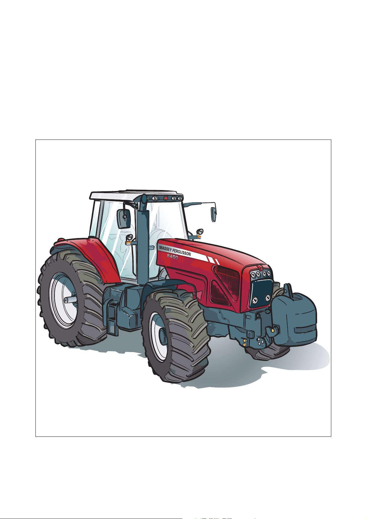
8400 Series Tractors
For models 8450 - 8460 - 8470 - 8480 Dyna VT
AGCO - SA - Beauvais - France - RC B562 104 539
MASSEY FERGUSON is a worldwide brand of AGCO Corporation
October 2006
N° 3378886M1
Issue 2
8400 EAME
English
Page 4

Page 5

OPERATOR INSTRUCTION BOOK
CONTENTS
Chapter 1
TRACTOR IDENTIFICATION
Chapter 2
INTRODUCTION - SAFETY INSTRUCTIONS AND WARRANTY
Chapter 3
INSTRUMENTS AND CONTROLS
Chapter 4
OPERATION
1
2
3
4
Chapter 5
MAINTENANCE AND ADJUSTMENTS
Chapter 6
SPECIFICATIONS
Chapter 7
ACCESSORIES AND OPTIONS
Appendix
CONVERSION TABLES
Index
5
6
7
8400 EAME
Page 6

Page 7

Chapter 1
1 . TRACTOR IDENTIFICATION
1
TRACTOR IDENTIFICATION
8400 EAME
1.1
Page 8

Page 9

1 . TRACTOR IDENTIFICATION
CONTENTS
1.1 - SERIAL NUMBER. . . . . . . . . . . . . . . . . . . . . . . . . . . . . . . . . . . . . . . . . . . . . . . . . . . . . . . . . . . . . . . . . . . . . . . . .1.5
1
8400 EAME
1.3
Page 10

1 . TRACTOR IDENTIFICATION
1.4
8400 EAME
Page 11
1 . TRACTOR IDENTIFICATION
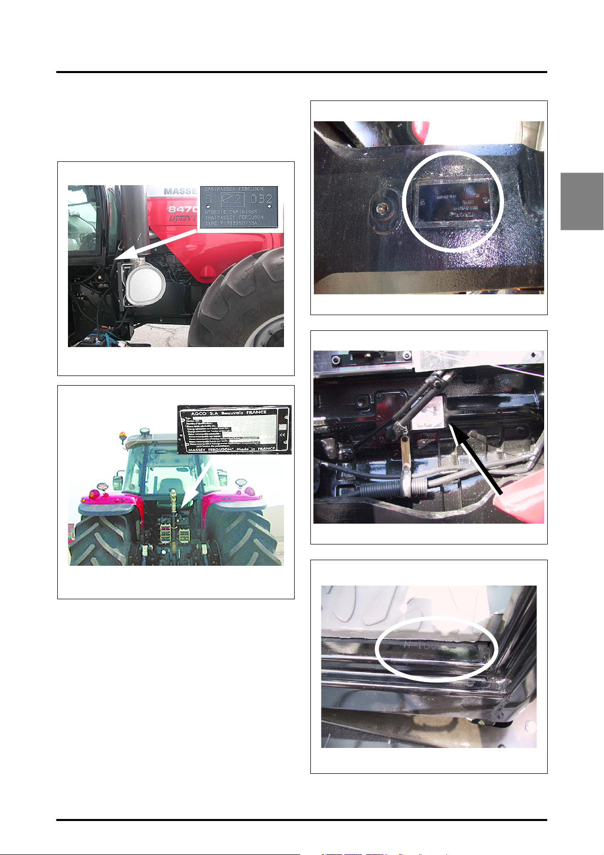
1.1 - SERIAL NUMBER
IMPORTANT: WHEN CONTACTING YOUR DEALER OR
AGENT, ALWAYS INDICATE YOUR TRACTOR SERIAL
NUMBER.
Registration plate (according to country)
Z3A-1131-09-
Z3A-1134-09-04
Fig. 1
Name plate with serial number (according to country)
Front axle serial number
Z4A-1631-11-05
"Sisu" engine serial number
1
Fig. 3
Z3A-1132-09-04
Z3A-1133-09-04
Fig. 2
Z4A-1630-11-
Cab serial number
Z3A-702-07-04
Fig. 4
Fig. 5
8400 EAME
1.5
Page 12

1 . TRACTOR IDENTIFICATION
MODEL:..............................................................................
............................................................................................
SERIAL NUMBER: ..............................................................
............................................................................................
ENGINE SERIAL NUMBER:................................................
............................................................................................
OWNER NAME AND ADDRESS (if applicable):
............................................................................................
............................................................................................
............................................................................................
............................................................................................
............................................................................................
............................................................................................
DEALER: ............................................................................
............................................................................................
............................................................................................
STREET: .............................................................................
TOWN:................................................................................
STATE: ................................................................................
ZIP CODE: ..........................................................................
DEALER CODE: .................................................................
............................................................................................
TRACTOR RECEIVED FROM:
(tick one of the following)
............................FACTORY
............................OTHER DEALER (transfer)
1.6
8400 EAME
Page 13

2 . INTRODUCTION - SAFETY INSTRUCTIONS AND WARRANTY
Chapter 2
2
INTRODUCTION - SAFETY INSTRUCTIONS AND
WARRANTY
8400 EAME
2.1
Page 14

Page 15

2 . INTRODUCTION - SAFETY INSTRUCTIONS AND WARRANTY
CONTENTS
2.1 - INTRODUCTION. . . . . . . . . . . . . . . . . . . . . . . . . . . . . . . . . . . . . . . . . . . . . . . . . . . . . . . . . . . . . . . . . . . . . . . . . .2.5
2.1.1 Pre-delivery inspection, commissioning at the user’s premises and warranty . . . . . . . . . . . . . . . . . . .2.5
2.1.2 Warranty procedure. . . . . . . . . . . . . . . . . . . . . . . . . . . . . . . . . . . . . . . . . . . . . . . . . . . . . . . . . . . . . . . .2.6
2.1.3 Using the tractor in another region . . . . . . . . . . . . . . . . . . . . . . . . . . . . . . . . . . . . . . . . . . . . . . . . . . . .2.6
2.1.4 Servicing after the warranty period . . . . . . . . . . . . . . . . . . . . . . . . . . . . . . . . . . . . . . . . . . . . . . . . . . . .2.6
2.2 - SAFETY - ALERT SYMBOLS AND TERMS. . . . . . . . . . . . . . . . . . . . . . . . . . . . . . . . . . . . . . . . . . . . . . . . . . . . .2.7
2.3 - TRACTOR AND IMPLEMENTS . . . . . . . . . . . . . . . . . . . . . . . . . . . . . . . . . . . . . . . . . . . . . . . . . . . . . . . . . . . . . .2.7
2.4 - MAXIMUM TRAVEL SPEEDS . . . . . . . . . . . . . . . . . . . . . . . . . . . . . . . . . . . . . . . . . . . . . . . . . . . . . . . . . . . . . . .2.8
2.5 - NOTE TO THE OPERATOR . . . . . . . . . . . . . . . . . . . . . . . . . . . . . . . . . . . . . . . . . . . . . . . . . . . . . . . . . . . . . . . . .2.8
2.6 - DANGER, WARNING AND CAUTION. . . . . . . . . . . . . . . . . . . . . . . . . . . . . . . . . . . . . . . . . . . . . . . . . . . . . . . . .2.8
2.7 - DECALS . . . . . . . . . . . . . . . . . . . . . . . . . . . . . . . . . . . . . . . . . . . . . . . . . . . . . . . . . . . . . . . . . . . . . . . . . . . . . . . .2.8
2.8 - SAFETY PROCEDURE TO FOLLOW . . . . . . . . . . . . . . . . . . . . . . . . . . . . . . . . . . . . . . . . . . . . . . . . . . . . . . . . . .2.8
2.8.1 For proper operation . . . . . . . . . . . . . . . . . . . . . . . . . . . . . . . . . . . . . . . . . . . . . . . . . . . . . . . . . . . . . . .2.8
2.8.2 Observe the following instructions . . . . . . . . . . . . . . . . . . . . . . . . . . . . . . . . . . . . . . . . . . . . . . . . . . . .2.9
2
2.9 - PROTECTION . . . . . . . . . . . . . . . . . . . . . . . . . . . . . . . . . . . . . . . . . . . . . . . . . . . . . . . . . . . . . . . . . . . . . . . . . . . .2.9
2.9.1 Cab . . . . . . . . . . . . . . . . . . . . . . . . . . . . . . . . . . . . . . . . . . . . . . . . . . . . . . . . . . . . . . . . . . . . . . . . . . . .2.9
2.9.2 Damage to the ROPS cab . . . . . . . . . . . . . . . . . . . . . . . . . . . . . . . . . . . . . . . . . . . . . . . . . . . . . . . . . . .2.9
2.10 - PREPARING FOR SAFE OPERATION . . . . . . . . . . . . . . . . . . . . . . . . . . . . . . . . . . . . . . . . . . . . . . . . . . . . . . . . .2.9
2.10.1 Know your equipment . . . . . . . . . . . . . . . . . . . . . . . . . . . . . . . . . . . . . . . . . . . . . . . . . . . . . . . . . . . . . .2.9
2.10.2 Protect yourself . . . . . . . . . . . . . . . . . . . . . . . . . . . . . . . . . . . . . . . . . . . . . . . . . . . . . . . . . . . . . . . . . .2.10
2.10.3 Use all available protective and safety devices . . . . . . . . . . . . . . . . . . . . . . . . . . . . . . . . . . . . . . . . . . 2.10
2.10.4 Equipment check. . . . . . . . . . . . . . . . . . . . . . . . . . . . . . . . . . . . . . . . . . . . . . . . . . . . . . . . . . . . . . . . .2.11
2.10.5 Clean the tractor . . . . . . . . . . . . . . . . . . . . . . . . . . . . . . . . . . . . . . . . . . . . . . . . . . . . . . . . . . . . . . . . .2.11
2.10.6 Protect the environment . . . . . . . . . . . . . . . . . . . . . . . . . . . . . . . . . . . . . . . . . . . . . . . . . . . . . . . . . . .2.12
2.11 - SERVICING THE TRACTOR. . . . . . . . . . . . . . . . . . . . . . . . . . . . . . . . . . . . . . . . . . . . . . . . . . . . . . . . . . . . . . . .2.12
2.12 - STARTING . . . . . . . . . . . . . . . . . . . . . . . . . . . . . . . . . . . . . . . . . . . . . . . . . . . . . . . . . . . . . . . . . . . . . . . . . . . . .2.12
2.12.1 Warn personnel before starting. . . . . . . . . . . . . . . . . . . . . . . . . . . . . . . . . . . . . . . . . . . . . . . . . . . . . .2.12
2.12.2 Get on and off the tractor safely . . . . . . . . . . . . . . . . . . . . . . . . . . . . . . . . . . . . . . . . . . . . . . . . . . . . .2.12
2.12.3 Start safely. . . . . . . . . . . . . . . . . . . . . . . . . . . . . . . . . . . . . . . . . . . . . . . . . . . . . . . . . . . . . . . . . . . . . . 2.12
2.12.4 Follow recommended start-up procedures . . . . . . . . . . . . . . . . . . . . . . . . . . . . . . . . . . . . . . . . . . . . .2.13
2.12.5 Controls test . . . . . . . . . . . . . . . . . . . . . . . . . . . . . . . . . . . . . . . . . . . . . . . . . . . . . . . . . . . . . . . . . . . .2.13
2.12.6 Starting fluid . . . . . . . . . . . . . . . . . . . . . . . . . . . . . . . . . . . . . . . . . . . . . . . . . . . . . . . . . . . . . . . . . . . .2.13
2.13 - WORKING SAFELY . . . . . . . . . . . . . . . . . . . . . . . . . . . . . . . . . . . . . . . . . . . . . . . . . . . . . . . . . . . . . . . . . . . . . .2.13
2.13.1 Make the right moves . . . . . . . . . . . . . . . . . . . . . . . . . . . . . . . . . . . . . . . . . . . . . . . . . . . . . . . . . . . . .2.13
2.13.2 Safety instructions to be observed . . . . . . . . . . . . . . . . . . . . . . . . . . . . . . . . . . . . . . . . . . . . . . . . . . .2.13
2.13.3 Safety of bystanders . . . . . . . . . . . . . . . . . . . . . . . . . . . . . . . . . . . . . . . . . . . . . . . . . . . . . . . . . . . . . .2.14
2.13.4 Risk of overturning . . . . . . . . . . . . . . . . . . . . . . . . . . . . . . . . . . . . . . . . . . . . . . . . . . . . . . . . . . . . . . .2.14
2.13.5 To avoid side overturns . . . . . . . . . . . . . . . . . . . . . . . . . . . . . . . . . . . . . . . . . . . . . . . . . . . . . . . . . . . . 2.15
2.13.6 To avoid rear overturns . . . . . . . . . . . . . . . . . . . . . . . . . . . . . . . . . . . . . . . . . . . . . . . . . . . . . . . . . . . .2.15
2.13.7 Emergency handbrake. . . . . . . . . . . . . . . . . . . . . . . . . . . . . . . . . . . . . . . . . . . . . . . . . . . . . . . . . . . . .2.16
2.13.8 Other risks. . . . . . . . . . . . . . . . . . . . . . . . . . . . . . . . . . . . . . . . . . . . . . . . . . . . . . . . . . . . . . . . . . . . . .2.16
2.13.9 Implements and attachments . . . . . . . . . . . . . . . . . . . . . . . . . . . . . . . . . . . . . . . . . . . . . . . . . . . . . . .2.17
2.13.10 Tractor Towing. . . . . . . . . . . . . . . . . . . . . . . . . . . . . . . . . . . . . . . . . . . . . . . . . . . . . . . . . . . . . . . . . . .2.18
2.13.11 Road use . . . . . . . . . . . . . . . . . . . . . . . . . . . . . . . . . . . . . . . . . . . . . . . . . . . . . . . . . . . . . . . . . . . . . . . 2.18
2.13.12 Highway code . . . . . . . . . . . . . . . . . . . . . . . . . . . . . . . . . . . . . . . . . . . . . . . . . . . . . . . . . . . . . . . . . . .2.18
2.14 - SAFETY - AFTER OPERATION . . . . . . . . . . . . . . . . . . . . . . . . . . . . . . . . . . . . . . . . . . . . . . . . . . . . . . . . . . . . .2.19
2.15 - DESCRIPTION OF DECALS . . . . . . . . . . . . . . . . . . . . . . . . . . . . . . . . . . . . . . . . . . . . . . . . . . . . . . . . . . . . . . . .2.20
8400 EAME
2.3
Page 16

2 . INTRODUCTION - SAFETY INSTRUCTIONS AND WARRANTY
2.4
8400 EAME
Page 17

2 . INTRODUCTION - SAFETY INSTRUCTIONS AND WARRANTY
2.1 - INTRODUCTION
The Safety chapter in the Operator Instruction Book stresses certain basic safety-related situations which may be encountered during the operation and normal servicing of the
tractor and gives the information needed to cope with
these situations. This chapter SUPPLEMENTS any safety
instructions given in other chapters of this book.
It may be necessary to take additional precautions depending on the equipment used and the working conditions on
the site or in the servicing area. AGCO can under no circumstances exercise direct control over the commissioning, operation, inspection, lubrication or servicing of the
tractor. It is therefore YOUR responsibility to take suitable
safety measures in such areas.
NOTE: This book is published and distributed worldwide and the availability of the equipment indicated,
whether on the basic tractor or as accessories, may
vary according to the country in which the tractor is
used. To find out which equipment is available in a
given region, contact an AGCO dealer.
The purpose of this book is to allow the owner and the operator to run the tractor safely. Providing they follow the instructions carefully, the tractor will operate for many years
in the AGCO tradition.
Commissioning the equipment at the user’s by the dealer
provides the possibility of ensuring that these operating
and servicing instructions are properly understood. Always
consult the dealer if any part of this book is not understood.
It is important for these instructions to be understood and
followed.
Daily maintenance should become a routine and a log book
of operating hours should be kept.
When new spare parts are required, it is important to use
AGCO original spare parts only. AGCO dealers supply only
genuine original parts and can give advice concerning their
fitting and use.
The use of parts of lower quality may cause serious damage. Customers are advised to only purchase their spare
parts from an approved AGCO dealer.
Due to the considerable differences in operating conditions, it is not possible for the manufacturer to formulate
complete or absolute assertions in its publications concerning the performance or operating methods of its machines
or accept liability for any loss or damage which may result
from such assertions or possible errors or omissions.
To prevent the warranty becoming void, you should consult
your AGCO dealer to obtain special instructions if the tractor is to be used under abnormal conditions which could be
detrimental to it (use in deep water or in paddy fields for instance).
These tractors are only designed for usual farming purposes (designed use).
Any other use is considered as being contrary to the designed use. AGCO declines all liability in cases of physical
damage or injuries resulting from improper use the consequences of which shall be borne by the user alone.
The conformity and strict adherence to the operating, servicing and repair requirements specified by AGCO are also
essential factors for designed use.
These tractors must only be used, serviced and repaired by
personnel having full knowledge of their specific features
and who are aware of the applicable safety rules (prevention of accidents).
Customers are strongly recommended to contact an AGCO
dealer in the event of after-sale problems and for any adjustments which may be necessary.
2.1.1 - Pre-delivery inspection, commissioning at the user’s premises and warranty
When selling new products to their dealers, the manufacturer gives a warranty which, subject to certain conditions,
guarantees that the goods are free from defects in material
and workmanship. Since this book is published worldwide,
it is impossible to detail the exact terms and conditions of
warranty that apply to a retail customer in any particular
country.
Purchasers of new AGCO equipment should request full
details from their supplying Dealer.
In accordance with the Corporation's policy of continuous
improvement to its products, alterations in the specifications of machines may be made at any time without notice.
The Corporation disclaims all liability for discrepancies
which may occur between the specifications of its products and the descriptions thereof contained in its publications.
A Dealer is required to carry out certain activities when supplying a new AGCO tractor. These consist of a full pre-delivery inspection to ensure that the tractor supplied is ready
for immediate use, and full instructions to the user in the
basic principles of operation and servicing of the tractor.
These instructions will cover instruments and controls, and
routine servicing and safety precautions. All persons who
will be concerned with the operation and servicing of the
tractor should be present for these instructions.
NOTE: AGCO disclaims all liability to any claim resulting from the fitting of non-approved parts, accessories,
implements or equipment or unauthorised modification or alteration.
2
8400 EAME
2.5
Page 18

2 . INTRODUCTION - SAFETY INSTRUCTIONS AND WARRANTY
2.1.2 - Warranty procedure
Correct commissioning at the user’s premises and routine
servicing contribute to preventing breakdowns. However,
if operating problems do occur during the warranty period,
follow this procedure:
Immediately inform the dealer you purchased the tractor
from, indicating the model and serial number. It is very important not to wait and it should be realised that, even if the
defect is covered by the original warranty, the risk coverage may no long apply if the repair is not carried out immediately.
Provide the dealer with as much information as possible.
The dealer will need to know how many hours the tractor
has been in service, what type of work it is used for and the
symptoms of the problem.
It should be noted that routine servicing operations such as
tuning, brake and clutch adjustment, and the supplies used
for the tractor servicing (oil, filters, fuel and antifreeze) are
not covered by the warranty.
Warning concerning spare parts
Parts other than AGCO parts are likely to be of lower quality. AGCO disclaims all liability in the event of loss or damage arising as a result of such parts being fitted. The
manufacturer’s warranty may also become void, if such
parts are fitted during the normal warranty period.
2.1.4 - Servicing after the warranty period
During the warranty period, all maintenance and repair
work must be carried out by the AGCO dealer who will
carefully carry out detailed checks of the progress and performance of the new tractor.
To obtain best results from an AGCO tractor, it is important
to continue regular servicing and periodic inspection after
the warranty has expired. All major overhaul work on the
tractor must be carried out by a local AGCO dealer; an experienced technician will detect any problems which may
arise between two overhauls.
Mechanical staff regularly follow training courses to update
their knowledge of the product, maintenance and repair
techniques and the use of special modern tools and equipment for troubleshooting. They receive regular Service Bulletins and have access to all the workshop manuals and
technical publications required to carry out repairs or maintenance meeting the quality standards required by AGCO.
2.1.3 - Using the tractor in another region
Only the AGCO dealer from whom the tractor was purchased is liable for the protection provided by the warranty.
Any repairs required should always, wherever possible, be
carried out by this dealer. If, however, the owner moves to
another region or if the tractor is to be used temporarily a
long way from the dealer it was bought from, it is recommended to ask this dealer for the name and address of the
AGCO dealer nearest the customer’s new address and arrange to have the obligations remaining to be fulfilled under
the warranty transferred to this dealer.
If the customer leaves the region covered by the original
dealer without having taken these steps, the new dealer
will offer its services if need be, but may bill them at the
normal rate unless:
• the user has effectively specified that the warranty
period has not expired and,
• the repair dealer has been given the possibility of taking
the necessary steps with the selling dealer.
2.6
8400 EAME
Page 19

2 . INTRODUCTION - SAFETY INSTRUCTIONS AND WARRANTY
2.2 - SAFETY - ALERT SYMBOLS AND
TERMS
This Safety Alert Symbol means CAUTION!
BE ALERT! YOUR SAFETY DEPENDS ON IT!
SAFETY is essential! Why?
• ACCIDENTS DISABLE AND KILL
• ACCIDENTS ARE COSTLY
• ACCIDENTS CAN BE AVOIDED
2.3 - TRACTOR AND IMPLEMENTS
The tractor is a source of power - Mechanical - Hydraulic
• On its own, the tractor is of little practical value. Only
when used in conjunction with an implement or other
attachment does it become a working unit.
• This Operator Instruction Book is compiled to cover the
safe working practices when the tractor runs under normal conditions.
• It does not cover all operation and safety instructions
relevant to all known implements and attachments that
may be fitted at the time of tractor delivery or later.
• It is essential that operators use and understand the relevant instruction books of such implements and attachments.
The safety alert symbol identifies important
safety messages on machines, safety signs, in
manuals, or elsewhere. When you see this
symbol, be alert to the risk of personal injury or
death. Follow the instructions in the safety
message.
2
8400 EAME
2.7
Page 20
2 . INTRODUCTION - SAFETY INSTRUCTIONS AND WARRANTY
2.4 - MAXIMUM TRAVEL SPEEDS
DANGER: Road use of agricultural tractors is
subject to speed restrictions depending on
the bulkiness of the equipment and weight of
the transported load. Consult the regulatory
texts in force in the relevant countries.
2.5 - NOTE TO THE OPERATOR
It is YOUR responsibility to read and understand the Safety
chapter in this book before starting your tractor. You must
follow these safety instructions that take you step by step
through your working day.
In reading this section, you will note that illustrations have
been used to highlight certain situations. Each item illustrated is numbered and the same number appears in the
text, in parentheses. This number is placed at the end of
the written text that refers to the item illustrated.
Remember that YOU are the key to safety. Good safety
practices not only protect you, but also bystanders. Study
the features in this book with care and make them a working part of your safety program. Keep in mind that this safety section is written only for this type of machine. Also
study the usual protective measures taken when working
and in particular -
REMEMBER THAT SAFETY DEPENDS ON YOU. YOU
CAN PREVENT SERIOUS INJURY OR DEATH.
2.6 - DANGER, WARNING AND CAUTION
Whenever you see the words and symbols shown below,
used in this book and on decals, you MUST apply their instructions as they relate to personal safety.
DANGER: This signal, displayed with the
word DANGER, indicates an imminently hazardous situation that, if not avoided, may
result in DEATH OR VERY SERIOUS INJURY.
WARNING: This signal, displayed with the
word WARNING, indicates a potentially hazardous situation that, if not avoided, may
result in DEATH OR SERIOUS INJURY.
IMPORTANT: Indicates a special instruction or procedure that, if not strictly observed may cause damage to,
or destruction of the machine, the process, or the surroundings.
NOTE: The word NOTE indicates additional information
about a subject or procedure for more efficient or convenient operation or repair.
2.7 - DECALS
WARNING: DO NOT remove or obscure DANGER, WARNING, CAUTION or Instruction
Decals.
Replace any Danger, Warning, Caution or Instruction Decals that are not readable or are missing. Replacement decals are available from your Dealer in the event of loss or
damage. The actual location of these Safety Signs is illustrated at the end of this chapter.
If a used tractor has been purchased, refer to the illustrations at the end of this book to ensure that all the safety
signs are in the correct position and are readable.
2.8 - SAFETY PROCEDURE TO FOLLOW
2.8.1 - For proper operation
For proper operation of an agricultural tractor, you must be
a qualified and approved operator. To be qualified you must
understand the written instructions supplied in this manual,
have training, and know the safety rules and regulations for
the job.
Some regulations specify that no one under the age of
16 years, for example, may operate power machinery. This
includes tractors. It is your responsibility to know what
these regulations are, and respect them, in the operating
area or situation.
These will include, but are not limited to, the following instructions for safe tractor operation.
WARNING: The operator must not drink alcohol or take any medication that may affect his
concentration or coordination. If taking medi-
cation, whether prescribed or not, the operator must seek medical advice as regards his ability to
safely operate machinery.
2.8
CAUTION: This signal, displayed with the
word CAUTION, indicates a potentially hazardous situation that, if not avoided, may
result in MINOR INJURY.
8400 EAME
Page 21
2 . INTRODUCTION - SAFETY INSTRUCTIONS AND WARRANTY
2.8.2 - Observe the following instructions
• DO NOT ALLOW children or unqualified persons to
operate your tractor. Keep others away from the working area.
• Always wear your seat belt securely fastened.
• Where possible, avoid operating the tractor near
ditches, embankments and holes. Reduce speed when
turning, crossing slopes, and on rough, slippery, or
muddy surfaces.
• Stay off slopes too steep for safe operation.
• Watch where you are going, especially at row ends, on
roads, and around trees.
• Instructor seat is only intended for short periods of use
• Do not allow children in the instructor seat.
• DO NOT PERMIT others to ride on the tractor or the
implement unless an approved instructor seat is fitted.
• Only hitch attachments and implements to the drawbar
and hitch points recommended, and never above the
centre line of the rear axle.
• Operate the tractor smoothly - no jerky turns, starts or
stops. When the tractor is stopped, apply the handbrake
securely. Lower the implement and remove the ignition
key.
• DO NOT MODIFY OR REMOVE any part of the equipment and DO NOT USE attachments unless they are
properly matched to your tractor.
2.9 - PROTECTION
2.9.1 - Cab
The ROPS (Roll Over Protective Structure) cab has been
designed for this tractor series and meets all the safety and
sound legal requirements.
The ROPS cab conforms to the various international safety
standards. The ROPS cab must NEVER be drilled or modified to install attachments or implements. Welding on cab
components IS NOT PERMITTED. DO NOT ATTACH
chains or ropes to the main frame of the cab for pulling purposes.
If additional controls or displays are to be added to the operator’s area contact your AGCO dealer for information.
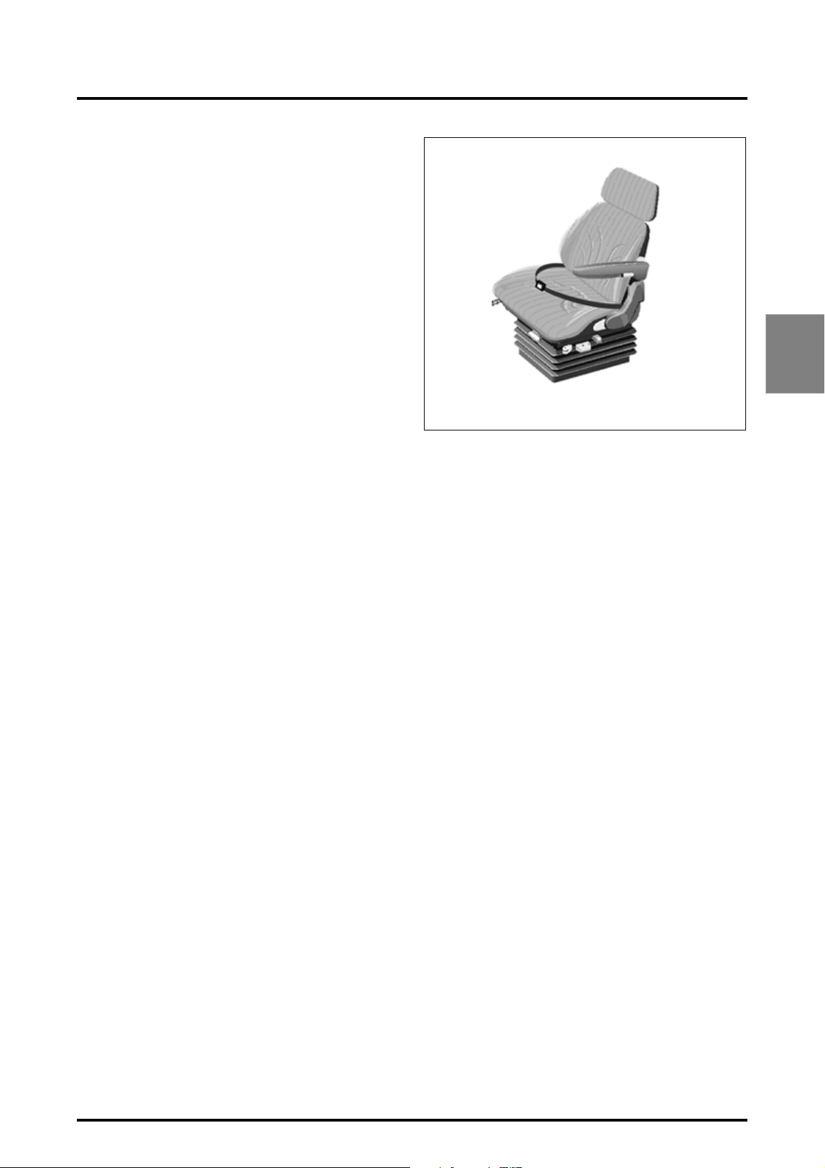
The ROPS cab together with the seat belt is effective in reducing injuries during overturn accidents. Wearing the seat
belt is an important part of this protection.
• Always wear your seat belt adjusted snugly.
• Check the seat belt for damage. A damaged seat belt
must be replaced (Fig. 1).
2
Z2-529-05-03
Fig. 1
2.9.2 - Damage to the ROPS cab
If the ROPS cab has been damaged as a result of tractor
rollover or incident, it must be replaced, NOT repaired.
DO NOT use the tractor with a damaged ROPS cab.
2.10 - PREPARING FOR SAFE OPERATION
2.10.1 - Know your equipment
It is important to know the tractor and operation of all its accessories, implements and additional equipment. It is also
important to know how to use all the controls, gauges and
dials, as well as the rated load capacity, speed range, braking and steering characteristics, turning radius, and operating clearances.
Remember that rain, snow, ice, loose gravel, soft ground,
etc. can change the performance of your tractor.
Under poor conditions, slow down and be extra careful,
and engage four-wheel drive if fitted.
Study the DANGER, WARNING and CAUTION safety
symbols on your tractor and the information signs also.
8400 EAME
2.9
Page 22
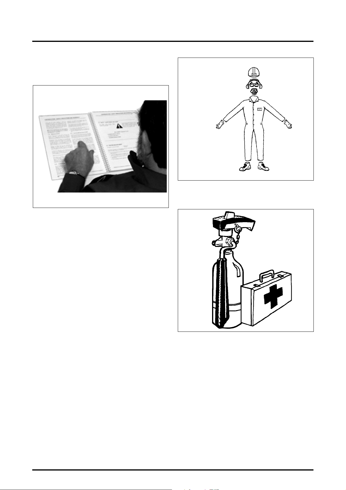
2 . INTRODUCTION - SAFETY INSTRUCTIONS AND WARRANTY
READ THIS OPERATOR INSTRUCTION BOOK CAREFULLY BEFORE STARTING THE ENGINE.
STUDY IT BEFORE YOU START WORK (Fig. 2).
Z2-530-05-03
IF THERE IS SOMETHING IN THE BOOK YOU DON’T UNDERSTAND, ASK SOMEONE (for example your equipment
dealer) TO EXPLAIN IT TO YOU.
This book covers general safety practice for agricultural
tractors. It must always be kept with the tractor. For extra
copies contact your AGCO Dealer.
2.10.2 - Protect yourself
Wear all protective clothing and equipment provided or
which is appropriate for certain working conditions. Do not
take any risks (Fig. 3).
For example, you may need:
• A safety helmet.
• Goggles, or a face shield.
• Hearing protection.
• Respirator or filter mask.
• Inclement weather clothing.
• Reflective clothing.
• Heavy gloves (neoprene for chemicals, leather for rough
work).
• Safety shoes.
DO NOT wear loose clothing, jewellery or other items and
tie up long hair which could catch on controls or other parts
of the equipment.
Fig. 2
Z2-531-05-03
Learn where fire extinguishers and first-aid or emergency
equipment is kept and where to get help in a hurry. Make
sure you know how to use this equipment (Fig. 4).
Fig. 3
Fig. 4
2.10.3 - Use all available protective and safety devices
Keep all protective devices correctly attached in their correct places. Ensure that all protective devices, guards and
safety signals are fitted as required and are in a good condition.
To help keep you and others around you safe, your tractor
should be equipped with:
•Seat belt.
• PTO shield
Your tractor may also need:
• Rear view mirror
• Fire extinguisher
• Emergency warning triangle, guards, backup alarm,
lighting devices and decals.
2.10
8400 EAME
Page 23
2 . INTRODUCTION - SAFETY INSTRUCTIONS AND WARRANTY
It is important to know and use the devices which allow for
safe operation of the tractor. Make sure all required equipment is in place and in good working order. DO NOT RE-
MOVE OR DISCONNECT any safety device.
2.10.4 - Equipment check
Before you begin your working day, take time to check your
tractor and ensure that all systems are in good operating
condition.
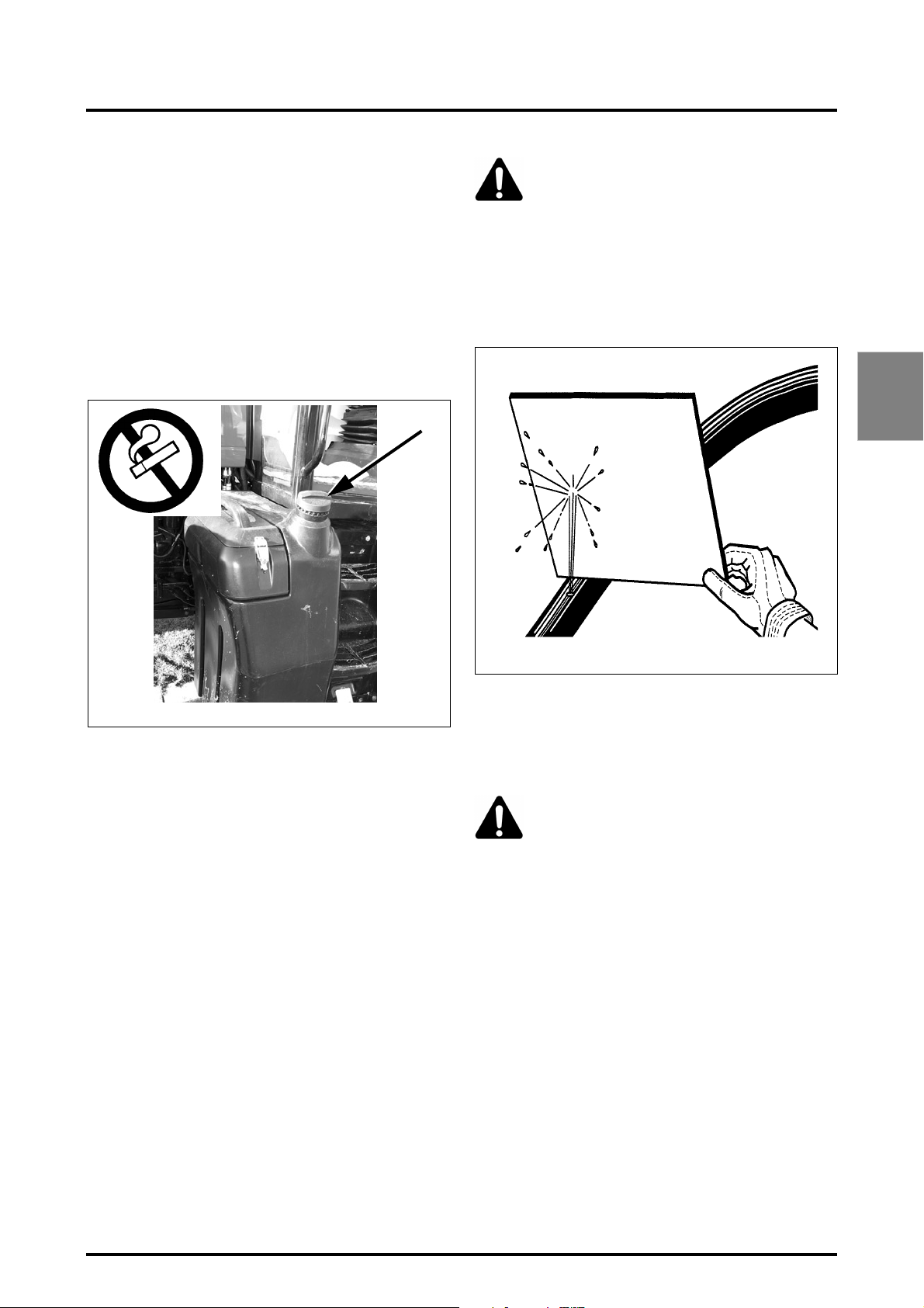
• DO NOT SMOKE while refuelling the tractor. Keep any
type of naked flame away (Fig. 5).
• Stop the engine and wait for it to cool before refuelling.
WARNING: Diesel fuel or hydraulic fluid under
pressure can penetrate the skin or eyes and
cause serious personal injury, blindness or
death.
Fluid leaks, under pressure, may not be visible. Use a
piece of cardboard or wood to detect leaks. DO NOT
USE YOUR BARE HANDS. Wear safety goggles for eye
protection. If any fluid is injected into the skin, it MUST
be surgically removed within a few hours by a doctor
familiar with this type of injury (Fig. 6).
2
Z2-532-05-03
• Check for loose, broken, missing, or damaged parts.
Have everything put into good repair. Make certain all
safety devices are in place.
• Check the seat belt for damage. A damaged seat belt
must be replaced.
• Check that all implements and equipment are correctly
fitted and that the tractor and implement PTO ratios
(rpm) are respected.
• Check the condition and pressure of tyres (absence of
cuts and bulges). Replace worn or damaged tyres.
Check the hand and foot brake operation. Adjust if necessary.
• Check the oil level. Add some oil if necessary.
• Perform all maintenance procedures outlined in the
Maintenance and Adjustments chapter in this Guide.
• Check that the PTO shaft locking devices are latched.
• Check that the tractor PTO shield and shaft guards are in
place and operating properly.
• Check the tractor and implement hydraulic system.
Have any leaks or damaged parts repaired or replaced.
Fig. 5
D-58 42A
Before applying pressure to the fuel or hydraulic system,
be sure all connections are tight and that lines, pipes, and
hoses are not damaged. Before disconnecting fuel or hydraulic lines, be sure to relieve all pressure.
Make sure that all hydraulic lines are correctly installed and
not crossed.
WARNING: Liquid cooling systems build up
pressure as the engine gets hot. Before
removing the radiator cap, stop the engine
and let the system cool.
• Check the engine cooling system and add coolant as
required.
2.10.5 - Clean the tractor
• Keep work surfaces and engine compartments clean.
• Before cleaning the machine, always lower implements
to the ground, place transmission in neutral, engage the
handbrake, stop the engine and remove the ignition key.
• Clean footsteps, pedals and floor. Remove grease or oil.
Brush away dust or mud. In winter, scrape away snow
and ice. Remember - slippery surfaces are hazardous.
• Remove or put away implements, buckets, chains and
hooks.
Fig. 6
8400 EAME
2.11
Page 24
2 . INTRODUCTION - SAFETY INSTRUCTIONS AND WARRANTY
2.10.6 - Protect the environment
• It is illegal to pollute drains, water courses or soil. Use
authorised waste disposal facilities, including civic
amenity sites and garages providing facilities for disposal of used oil. If in doubt, contact your local authority
for advice.
2.11 - SERVICING THE TRACTOR
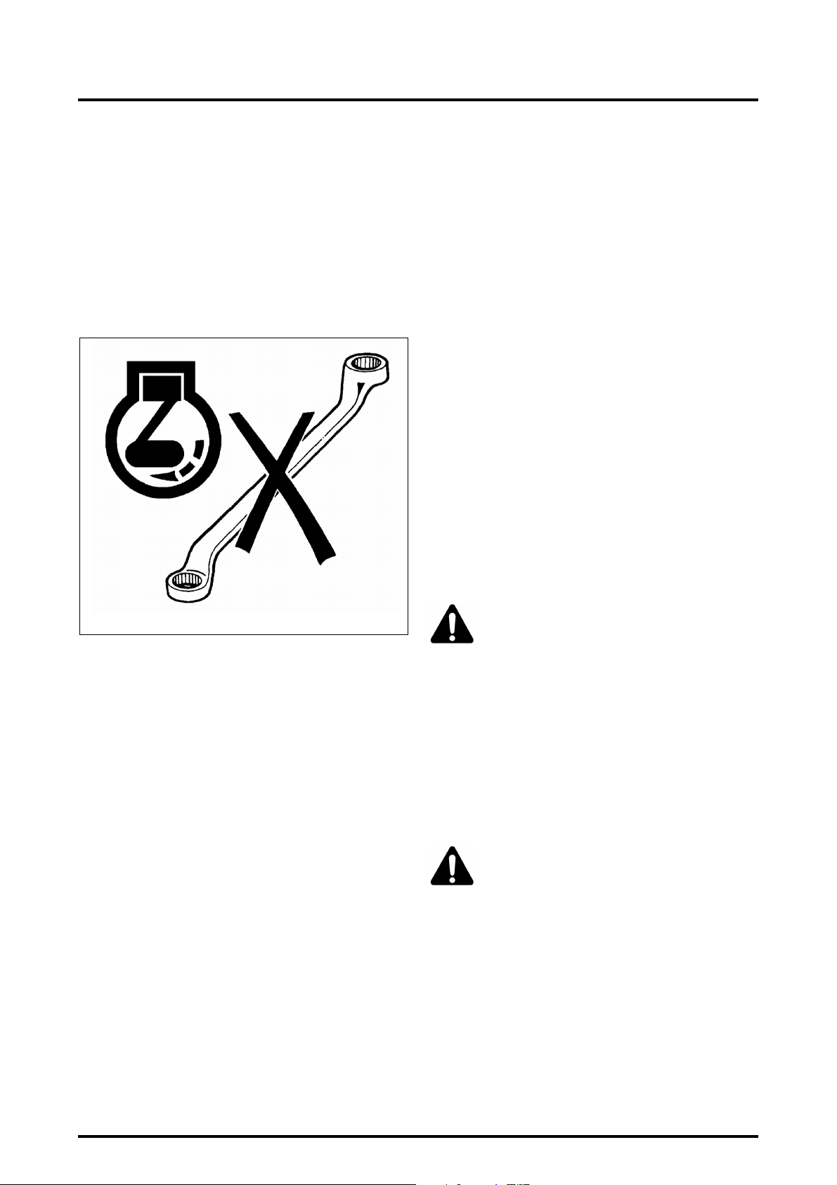
• DO NOT SERVICE the tractor while the engine is running or hot, or if the tractor is in motion (Fig. 7).
2.12 - STARTING
2.12.1 - Warn personnel before starting
Before starting, walk completely around the tractor and any
attached equipment. Make sure that no one is under it, on
it, or close to it. Tell other workers or people nearby that the
tractor is about to start. Do not start the tractor while there
are people near the tractor, tools or trailed implements.
Ensure that all bystanders, particularly children, are a suitable distance away before starting the engine.
2.12.2 - Get on and off the tractor safely
Always use "three point contact" with the machine, and
face the machine when you get on it. (Three point contact
means both hands and one foot or one hand and both feet
are in contact with the machine at all times when getting
on and off).
Clean your shoes and wipe your hands before getting on.
Use handrails, grab handles, ladders or footsteps (as provided) when getting on and off.
DO NOT use control levers as a hand hold and never step
on pedals when getting on and off.
DO NOT attempt to get on or off a moving tractor. DO NOT
JUMP off a tractor other than in an emergency.
Z2-534-05-03
Fig. 7
• Before making adjustments to or servicing the electrical
system, disconnect the battery cables, negative (-) cable
first.
• To prevent fires or explosions keep open flame away
from the battery or cold weather starting aids. To prevent sparks which could cause explosions use jumper
cables according to instructions.
• When making repairs or adjustments it is recommended
that you consult your AGCO Dealer, and have the work
carried out by trained personnel.
• The implement and/or tractor must be supported on
suitable blocks or stands, NOT a hydraulic jack.
• Check all nuts and bolts periodically for tightness, especially wheel hub and rim nuts. Tighten to the prescribed
torque values.
2.12.3 - Start safely
WARNING: Before starting the engine make
sure there is plenty of ventilation. DO NOT
operate the engine in a closed building. The
exhaust fumes may cause asphyxiation.
Always start the engine from the driver’s seat with all the
transmission levers and the PTO lever in neutral.
Make sure that the tractor dual brake pedals are locked together at all times unless you are making turns in the field
which require independent use of the brakes. Make sure
the brakes are properly adjusted so that both brakes engage at the same time.
Adjust the seat, fasten the seat belt (as specified in the
book), apply the handbrake and put all controls in neutral
before starting up.
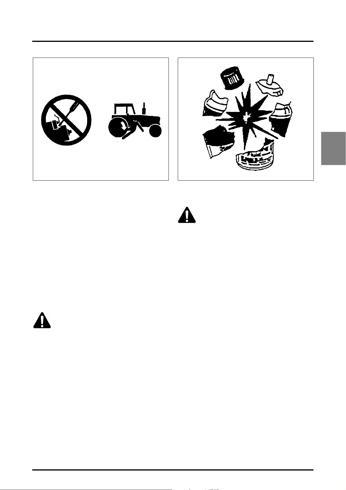
DANGER: Start the engine, with the ignition
key, from the driver’s seat only. DO NOT
ATTEMPT to start the engine by shorting
across the starter terminals. The machine will
start in gear if the neutral start circuit is bypassed. This
could cause serious injury or death to anyone in the
vicinity of the tractor (Fig. 8).
2.12
8400 EAME
Page 25
2 . INTRODUCTION - SAFETY INSTRUCTIONS AND WARRANTY
Z2-535-05-03
Fig. 8
2.12.4 - Follow recommended start-up procedures
Follow the start-up procedures recommended in the Operation chapter of this Operator instruction Book. This chapter includes normal starting, cold starting, and the use of
starting fluids.
2.12.5 - Controls test
After starting, check all gauges and lights again. Make sure
everything is functioning correctly. If the tractor does not
respond correctly when each control is operated, DO NOT
USE the machine until the fault is remedied.
Ensure that the starter solenoid cover is always in position.
2.12.6 - Starting fluid
WARNING: It is very important that you read
and follow the starter fluid instructions before
using it. DO NOT use aerosol cans of starter
fluid on tractors with the thermostat connected to the electrical system. Ether combined with
thermostat can cause an explosion with damage to
engine, personal injury, or both.
Handle starting fluid correctly. Starting fluid must only be
used in conjunction with an ether-start aid fitted as original
equipment by the manufacturer or installed by a Dealer as
an accessory. In cases of tractors being fitted with glow
plugs or a thermostat, these must be removed prior to the
installation of an ether-start aid (Fig. 9).
If aerosol cans of starting fluid are to be used the thermostat must be disconnected. Remove the wire from the
thermostat which will be found on the manifold. Tape the
end of the wire to prevent an electrical short circuit.
WC1952
Fig. 9
2.13 - WORKING SAFELY
WARNING: An unbalanced tractor could overturn and cause injury or death.
Make sure front frame counterweights, wheel
weights and wheel ballast are used as recommended by the manufacturer. DO NOT add extra counterweights to compensate for an overloaded tractor; it
is recommended to reduce the load. Keep all parts of
your body inside the cab while operating the tractor.
2.13.1 - Make the right moves
Ensure that the tractor is ready for the work to be carried
out. Make sure you know the tractor nominal load capacities and never exceed them. Be certain that any attachments or implements you intend to use DO NOT EXCEED
the load rating of your tractor. Be sure the tractor and implement PTO speed match.
Keep in mind that tractors normally operate on uneven, unpaved, and often bumpy or sloping surfaces. Operating
conditions can reduce the amount of weight you should
carry or pull.
2.13.2 - Safety instructions to be observed
• Operate the controls smoothly - don’t jerk the steering
wheel or other controls.
• NEVER get on or off a moving tractor. Keep a firm grip
on the steering wheel at all times, with the thumbs clear
of the spokes when driving the tractor.
• Make sure you have adequate clearance in all directions
for the tractor and implement.
• DO NOT play with a tractor or equipment. Use only for
intended purpose.
• DO NOT attempt to work the controls except from the
driver’s seat.
2
8400 EAME
2.13
Page 26
2 . INTRODUCTION - SAFETY INSTRUCTIONS AND WARRANTY
• Before getting off, always disengage the PTO, lower all
attachments and implements to the ground, set the
tractor to neutral, activate the ParkLock, stop the engine
and remove the ignition key.
NOTE: DO NOT TOUCH, lean on, or reach through any
implement mechanism or permit others to do so.
Stay alert! If a part breaks, loosens or does not operate
correctly, stop work, switch off the engine, check the machine and carry out any necessary adjustments or repairs
before resuming work.
2.13.3 - Safety of bystanders
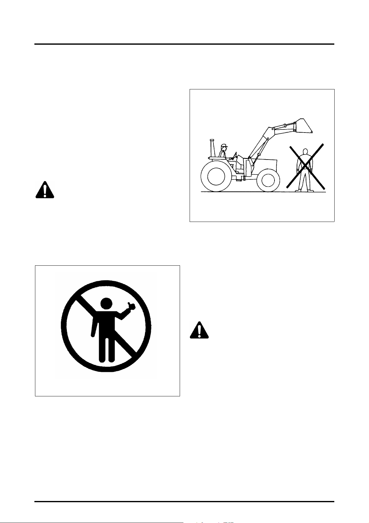
Watch out for others. DO NOT allow inexperienced or unqualified people to operate the tractor. They may cause injury to themselves or to others.
WARNING: A tractor is a personal piece of
machinery. Do not allow others to drive the
tractor or to use the implement (Fig. 10). DO
NOT ALLOW another person to get on the
implements or any other equipment, including trailers,
except in the case of harvesters specially designed for
this purpose (for the harvest itself and not for transport
purposes). Space should be provided on such equipment so that this type of transport can be carried out
in complete safety. DO NOT ALLOW children on the
tractor.
• Keep others away from the working area. DO NOT
ALLOW others to stand beside or walk beneath a raised
implement (Fig. 11).
S-1125
Fig. 11
• DO NOT lift objects that do not fit safely into the
bucket. Obtain the correct equipment.
• When using a loader, avoid sudden stops, starts, turns,
or change of direction. Keep loads close to the ground
when transporting.
• DO NOT stand (or allow anyone else to stand) in front
of, under, or behind loaded or loading equipment. DO
NOT DRIVE a tractor up to someone standing in front of
a fixed object.
• Keep others away from universal joints, hitches, drawbars, lift arms, PTO shafts, cylinders, belts, pulleys, and
other moving parts. Keep all shields and guards in place.
WARNING: DO NOT STAND, or allow anyone
else to stand, between the tractor and implement unless the engine is turned off and the
handbrake is engaged, the transmission control lever is in neutral, and all attachments or implements are lowered to the ground.
Z2-536-05-03
Fig. 10
• Be certain you can control both speed and steering
before moving. Move slowly until you are sure that
everything is operating properly. After starting, recheck
the steering, right and left. Be certain you have full
steering and brake control. If differential is locked, DO
NOT operate at high speed or turn the tractor until the
differential lock is disengaged.
• DO NOT LIFT a load over anyone.
2.14
2.13.4 - Risk of overturning
In the event of an overturn with a tractor fitted with a cab,
hold the steering wheel firmly and do not attempt to leave
the seat until the tractor has come to a standstill (Fig. 12).
If the doors of the cab are obstructed, leave through the
rear window or roof hatch.
8400 EAME
Page 27
2 . INTRODUCTION - SAFETY INSTRUCTIONS AND WARRANTY
Z2-538-05-03
Fig. 12
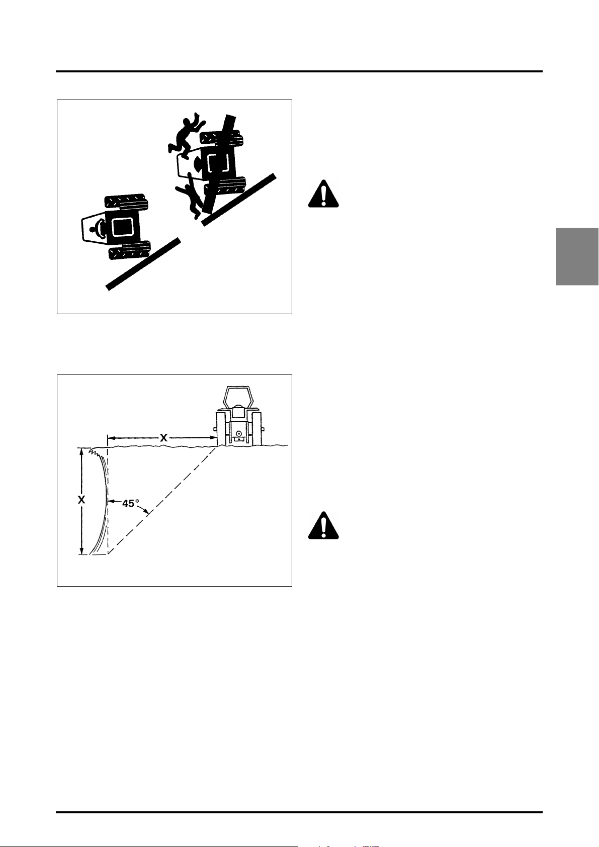
Fig. 13: Do not operate near the edge of ditches or banks.
The distance from the edge should always be equal to or
greater than the height of the bank, to prevent it from collapsing.
• When driving down a slope, use the gas control to slow
the tractor engine and choose the same gear ratio as
used when climbing a slope. Shift into gear before you
start downhill.
• Engage four-wheel drive (if fitted), this will give fourwheel braking.
WARNING: DO NOT disengage the clutch or
attempt to shift gear after you have started
downhill.
• The tractor is less likely to turn over if you drive up or
down a steep slope rather than driving across it.
• Avoid steep slopes whenever possible. If this is not possible, avoid holes and dips when driving downhill. Avoid
stumps, stones, bumps and raised areas when driving
uphill. Keep the tractor behind the shear line when
working close to ditches or banks. (Fig. 13). Avoid
ditches, banks and riversides which might give way.
• When you must drive on a steep slope, avoid turning at
the top of the slope. Slow down and turn in a wide turning circle. Drive straight on uphill or downhill slopes, and
never drive across them. Keep the heavier end of the
tractor facing towards the top of the slope when driving
up and down it.
• If a tractor fitted with lateral implements is used on a
steep slope, the implement must always face up the
slope. Do not raise implements. Keep them as low to
the ground as possible when crossing a slope.
• When towing a load at transport speed, lock the drawbar in the centre position and use a safety chain.
• DO NOT use your tractor to round up farm animals.
2
S-1031
Fig. 13
2.13.5 - To avoid side overturns
• Set the wheel track at the widest setting suitable for the
work being done.
• Lock the brake pedals together before driving at transport speeds.
• Reduce speed to match operating conditions. If the tractor is equipped with a front-end loader, carry the bucket
and load as low as possible.
• Make wide slow turns at reduced speed. Don’t let your
tractor bounce. You may lose steering control.
• Don’t pull a load too heavy for your tractor. It could run
down the slope or the tractor could jackknife around a
towed load.
• Don’t brake suddenly. Apply brakes smoothly and gradually.
2.13.6 - To avoid rear overturns
WARNING: Hitching to the rear axle, or any
other point above the swinging drawbar, can
cause a rear overturn.
• DO NOT PULL anything using the top link connection,
or from any point on the rear axle or above. Always use
an approved AGCO drawbar, and only use a drawbar pin
of the correct size and that can be locked in place.
• High hitching can cause rear overturn, which may cause
serious injury or death. Hitch loads to the drawbar only.
• Only use a three-point linkage drawbar when stays are
fitted to keep it in the down position.
• Use front counterweights to increase tractor stability
when towing a heavy load or to counterbalance a heavy
rear mounted implement.
• Start forward slowly and gradually increase your speed.
DO NOT reverse or release the clutch. If the tractor is
attached to a heavy load or immovable object, improper
clutching may cause rear overturn.
• If the front end of the tractor starts to lift, reduce your
speed and, if necessary, disengage the clutch.
8400 EAME
2.15
Page 28
2 . INTRODUCTION - SAFETY INSTRUCTIONS AND WARRANTY
• If your tractor is bogged down in mud or frozen to the
ground, DO NOT attempt to drive forward. The tractor
can rotate around its rear wheels and overturn. Lift any
attached implement and attempt to BACK OUT. If this
is not possible, tow it out with another vehicle.
• If you get stuck in a ditch, BACK OUT, if possible. If you
must go forward, do so slowly and carefully.
• A bare tractor or tractor with rear mounted attachments
should be backed up the slope in reverse and travel forward downhill.
• A tractor with a loaded front-end bucket should be
backed down the slope and travel forward uphill. Keep
the loader bucket as low as possible.
• Always keep the tractor in gear when going downhill.
DO NOT PERMIT the tractor to coast with clutch disengaged or transmission in neutral.
2.13.7 - Emergency handbrake
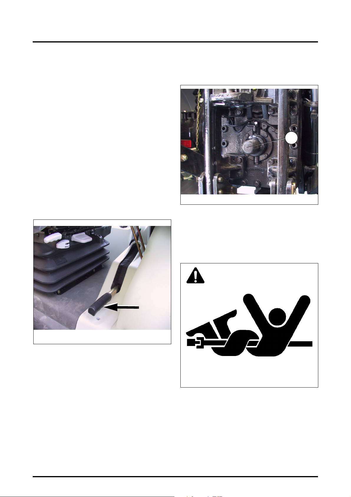
IMPORTANT: If the brakes fail and in an emergency situation, use the emergency handbrake located to the left
of the driver (Fig. 14)
2.13.8 - Other risks
• Ensure that the PTO shield (1) is in place when the PTO
driveline is not in use (Fig. 15).
1
Z3A-740-07-04
• Before attaching, detaching, cleaning or adjusting PTO
driven implements, disengage the PTO, stop the
engine, remove the ignition key, and make sure that the
PTO transmission shaft has stopped.
• Ensure that all the PTO transmission shaft guards and
shields are in place and check the presence of all safety
decals (Fig. 16).
Fig. 15
Z3A-780-07-04
Fig. 14
DANGER: Do not use the emergency handbrake as a
parking brake. The parking brake to be used is the
"ParkLock" brake control on the steering wheel.
IMPORTANT: If the brakes fail, contact an approved
AGCO dealer to have them repaired.
DANGER
Z2-541-05-03
Fig. 16
• Be sure everyone is clear of your machine before engaging the PTO. For stationary PTO operation, always place
transmission control lever in neutral, engage handbrake,
and chock both tractor and implement wheels.
• When operating mobile PTO driven equipment, DO
NOT leave the tractor seat until the PTO drive is disengaged, the transmission is in neutral, the handbrake is
engaged, the engine shut off and the ignition key
removed.
2.16
8400 EAME
Page 29
2 . INTRODUCTION - SAFETY INSTRUCTIONS AND WARRANTY
• DO NOT use PTO adapters, reducers or extensions as
they extend the PTO coupler and universal joint out
beyond the protection offered by the PTO shield.
• The deployment of drawbars and lift rods must not
allow the threads to show.
DANGER: DO NOT attempt to unplug the
hydraulic connections, or adjust an implement with the engine running or the PTO
drive in operation. To do so may result in seri-
ous injury or death.
• When using chemicals, carefully follow the chemical
manufacturer’s instructions for use, storage and disposal. Also follow the chemical application equipment
manufacturer’s instructions.
• When operating under poor visibility conditions, or in the
dark, use your tractor work headlights and reduce your
ground speed (DO NOT use your work headlights when
travelling on a roadway because rear pointed white
lights are illegal except when reversing and may confuse following drivers).
• Operate your tractor with tyres of suitable width, consistent with the particular task you are performing. To
adjust tyre width, see chapter Maintenance and Adjustments.
• Reduce your speed when operating over rough or slippery ground and when foliage restricts your view of hazards.
• DO NOT make sharp turns at high speed.
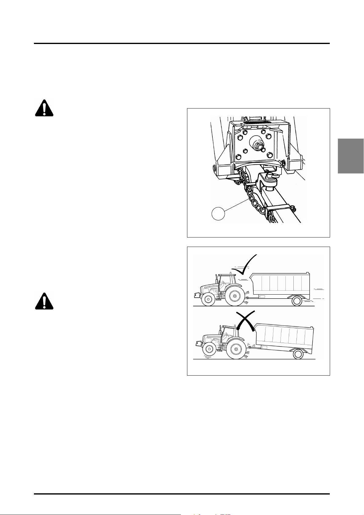
• Ensure that all trailed implements are fitted with a
safety chain linking the tractor to the implement, if
required by law (Fig. 17).
• Pull only from the approved drawbars. Towing or attaching to other locations may cause the tractor to overturn
(Fig. 18).
2
1
Z2-542-05-03
Fig. 17
2.13.9 - Implements and attachments
WARNING: A front-end loader (bucket or
forks) must be equipped with a suitable holding device to prevent the load (bales, fence
posts, rolls of fence, wire etc.) from rolling
down the lift arms into the driver’s compartment and
crushing the driver when the loader is raised. Inadequately secured objects could also fall and injure
bystanders.
• Three-point hitch and side mounted implements make a
much larger arc when turning than towed equipment-.
Make certain to maintain sufficient clearance for turning.
Use only AGCO approved equipment.
• When using attachments or implements with the trac-
tor, be sure to read and understand the instructions in
the Operator Instruction Book for that attachment or
implement and follow its safety instructions. Use only
AGCO approved attachments and implements.
• DO NOT overload a towed attachment or equipment.
Use proper counterweights to maintain tractor stability.
Hitch loads to the drawbar only.
• A transport chain 1 will help control drawn equipment
should it be accidentally separated from the drawbar
while transporting. Using the appropriate adapter parts,
attach the chain to the tractor’s safety chain anchor or
any other specified anchor point. Provide only enough
slack in the chain to permit turning. Contact your AGCO
dealer for a chain of equal or greater strength than the
weight of the trailed implement (Fig. 17).
Z2-543-05-03
Fig. 18
8400 EAME
2.17
Page 30
2 . INTRODUCTION - SAFETY INSTRUCTIONS AND WARRANTY
2.13.9.1 - Safety measures when towing
• For towed equipment WITHOUT brakes, DO NOT tow
equipment:
- at speeds exceeding the speed limits in force in the
relevant country,
- at a maximum load higher than that indicated on the
name plate.
• For towed equipment WITH BRAKES, DO NOT tow
equipment:
- at speeds exceeding the speed limits in force in the
relevant country,
- at a maximum load higher than that indicated on the
name plate.
NOTE: The tractor requires correct trailer braking system installed and connected to the equipment.
Stopping distance increases with speed and weight of
towed loads, and on hills and slopes.
Towed loads with or without brakes that are too heavy for
the tractor or are towed too fast can cause loss of control.
Consider the total weight of the equipment and its load.
2.13.10 - Tractor Towing
See chapter 4.
WARNING: Towing: the following instructions must be followed when towing:
Z2-544-05-03
2.13.12 - Highway code
When operating your tractor on a public road the following
precautions must be taken.
WARNING: NEVER allow any persons to ride
on the tractor or towed equipment.
Fig. 19
If the engine is not running:
• Maximum towing speed: 10 kph.
• Maximum towing distance: 8 km.
If the engine is running:
Towing speed is identical to that of a trailer without brakes
at the speed authorised by legislation in force in the country concerned.
2.13.11 - Road use
Take the following precautions before using the tractor on
a public road.
• Respect national laws and local regulations in force
relating to tractor use.
• Lock the brake pedals together.
• Place all implements in transport position and lock.
• Place all implements into their narrowest transport configuration.
• Disengage the PTO and differential lock.
• Make sure any required clearance flags or hazard warning lights are in place and in working order.
• Clean off all reflectors and road lights, front and rear,
and be certain they are in working order.
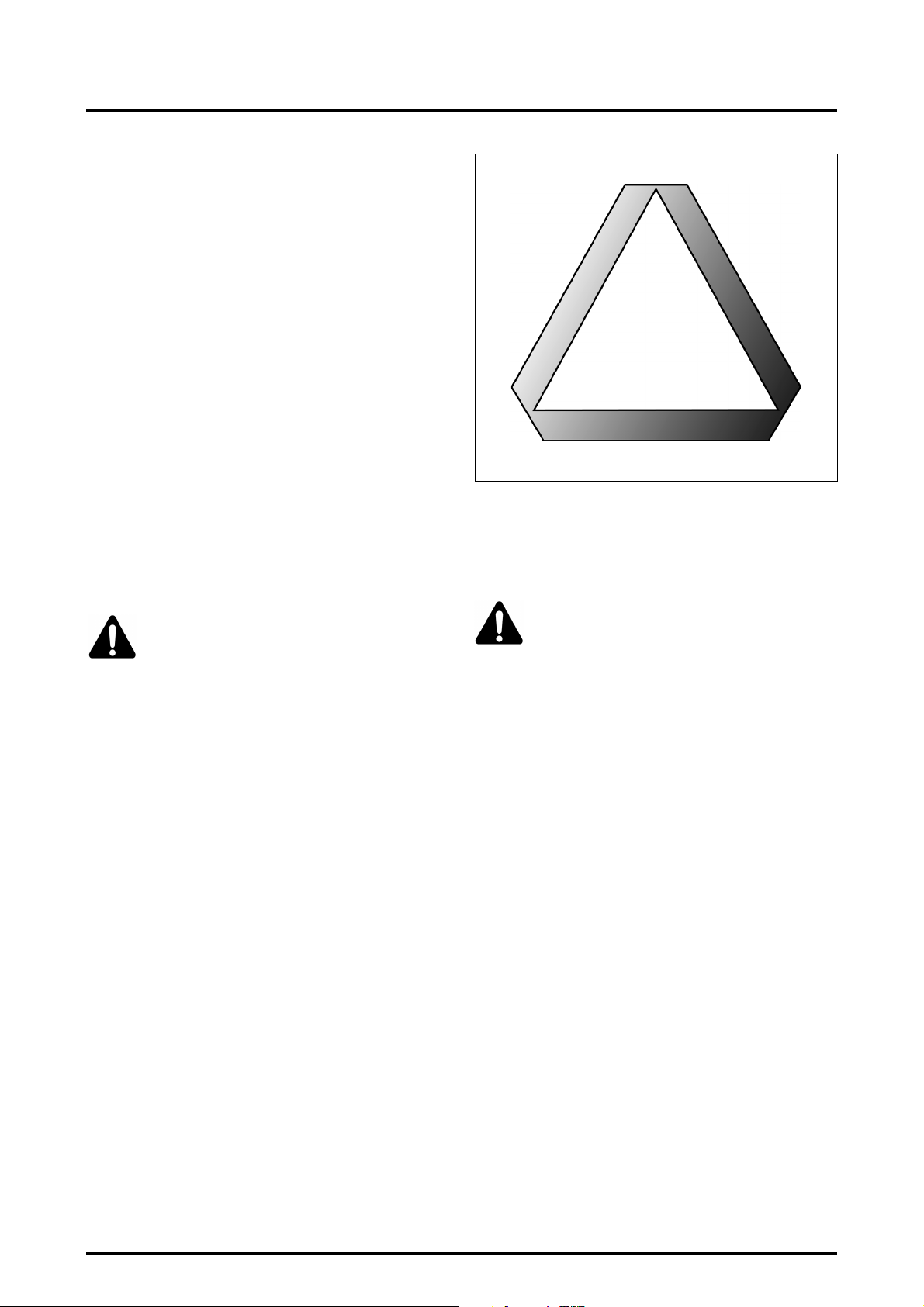
• Ensure that the tractor and equipment are fitted with
emergency warning triangles and other markings recommended to improve visibility when driving on roads,
unless otherwise indicated (Fig. 19).
• Know the road you are going to travel.
• Turn on hazard warning lights when travelling on roads,
day or night, unless prohibited by law.
• Take care when towing a load at transport speeds,
especially if the towed equipment is NOT fitted with
brakes.
• Observe all local or national regulations regarding the
road speed of your tractor.
• Use extreme caution when transporting on snow-covered or slippery roads.
• Wait for traffic to clear before entering a public road.
• Beware of blind intersections. Slow down until you have
a clear view.
• DO NOT attempt to pass at any intersection.
• Slow down for turns and curves.
• Make wide, gentle turns.
• Signal your intent to slow, stop or turn.
• Shift to a lower gear before going up or down hills.
• Keep tractor in gear. Do not coast with the clutch disengaged or transmission in neutral.
• Stay out of the path of oncoming traffic.
• Drive in your correct lane keeping as near to the curb as
possible.
• If traffic builds up behind you, pull off the road and let it
go by.
• Drive carefully. Anticipate what other drivers might do.
• When towing a load, start braking sooner than normal
and slow down gradually.
• Watch out for overhead obstructions.
2.18
8400 EAME
Page 31

2 . INTRODUCTION - SAFETY INSTRUCTIONS AND WARRANTY
• Make sure load does not obscure hazard warning or
transport lights.
2.14 - SAFETY - AFTER OPERATION
Whenever stopping, bring the tractor to a complete halt,
apply the parking brake, disengage the PTO, place the
PowerShuttle lever in neutral position, lower the implement to the ground, stop the engine and remove the ignition key BEFORE leaving the seat.
DANGER: PowerShuttle control: Before leaving the seat it is mandatory to move the PowerShuttle control to NEUTRAL position.
Remove ignition key if the tractor is to be left
unattended.
IMPORTANT: Electromechanic ParkLock control: Move
lever to locked position (symbol: closed padlock) to
engage ParkLock before stopping the engine.
2
8400 EAME
2.19
Page 32
2 . INTRODUCTION - SAFETY INSTRUCTIONS AND WARRANTY
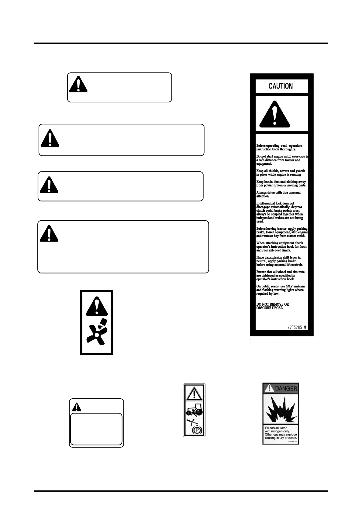
2.15 - DESCRIPTION OF DECALS
High pressure steam and hot water.
Remove filler cap with extreme care.
CAUTION
DO NOT REMOVE OR OBSCURE DECAL
3595685 M1
Located on top of the bonnet (access to
radiator cap)
CAUTION
Before working on the tractor, disconnect negative leads to all Battery.
CAUTION
Before removing any battery, disconnect all negative leads before positive
leads.
DO NOT REMOVE OR OBSCURE DECAL
Located on the battery cover.
Keep all shields, covers and guards fastened
in place while engine is running.
WARNING
CAUTION
Beware hot parts.
DO NOT REMOVE OR OBSCURE DECAL
Located on the right- and left-hand sides of the bonnet
CAUTION
Always disengage PTO and stop engine
before attaching or detaching PTO
shafts or working on PTO driven equipment.
Always fit PTO cover when PTO is not in
use.
Do not stand between tractor and equipment when operating controls.
Tow only with MF approved tractor drawbar or hitch.
WARNING
3595679 M1
3595678 M1
Located at the rear of the tractor
4271915M1
Located to the left
and right of the
radiator.
CAUTION
TO AVOID POSSIBLE TRACTOR OVERTURN, TOW ONLY
FROM THE DRAWBAR OR
LOWER LINKS OF THREE
POINT HITCH.
2752579 M1
Located on the
fenders to the rear of
the cab
DO NOT REMOVE OR OBSCURE DECAL
3581563 M1
3782489 M1
Located on the RH
inner column of the
cab
Located on the RH
inner column of the cab
3777021M2
Located on the
accumulator.
2.20
8400 EAME
Page 33
2 . INTRODUCTION - SAFETY INSTRUCTIONS AND WARRANTY
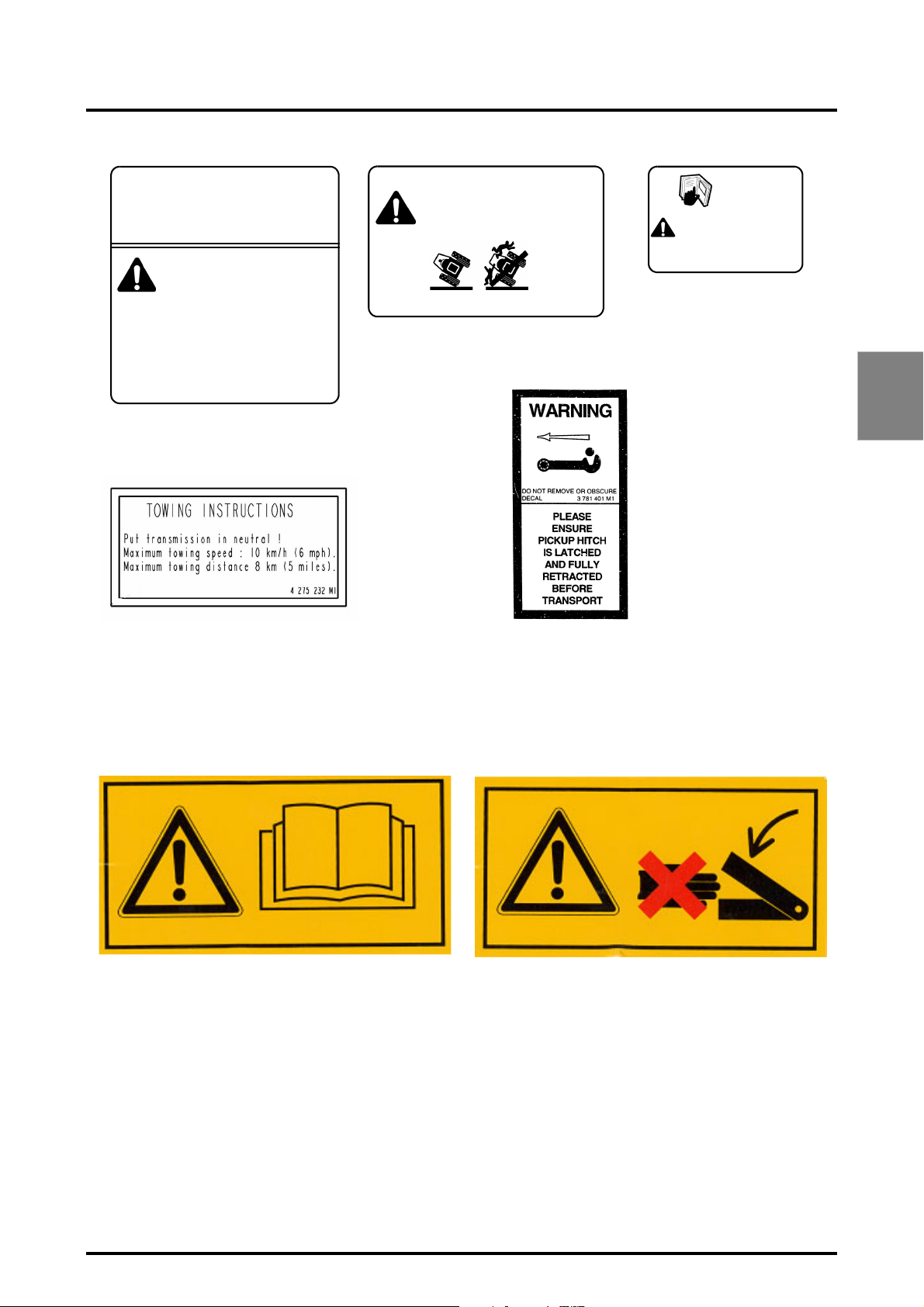
CAUTION
Before working on the tractor or removing this cover, disconnect negative leads
to all Battery.
WARNING
Do not short across starter terminals to
start engine.
Never start engine while standing on the
ground.
Start engine only with start key from operator's seat, ensuring that gearbox and
PTO are in neutral with parking brake applied.
DO NOT REMOVE OR OBSCURE DECAL
3596432 M1
Located on the starter motor.
Located on the inner side of the right-
handed door.
WARNING
If tractor is overturning, hold onto the steering wheel.
Do not leave seat.
DO NOT REMOVE OR OBSCURE DECAL
3580315 M1
Located at the rear of the instructor seat.
IT IS IMPERATIVE TO USE
THE TRANSMISSION OIL
RECOMMENDED IN THE OPERATING MANUAL.
3713699 M1
Located on the fenders
to the rear of the cab
2
Front linkage decals
WARNING: Read the Operator Instruction Book
before starting work.
DANGER: Avoid being caught by moving parts
8400 EAME
2.21
Page 34

Page 35

3 . INSTRUMENTS AND CONTROLS
Chapter 3
3
INSTRUMENTS AND CONTROLS
8400 EAME
3.1
Page 36

Page 37

3 . INSTRUMENTS AND CONTROLS
CONTENTS
3.1 - INSTRUMENT PANEL (FIG. 1) . . . . . . . . . . . . . . . . . . . . . . . . . . . . . . . . . . . . . . . . . . . . . . . . . . . . . . . . . . . . . .3.5
3.2 - INDICATOR LIGHTS PANEL . . . . . . . . . . . . . . . . . . . . . . . . . . . . . . . . . . . . . . . . . . . . . . . . . . . . . . . . . . . . . . . .3.7
3.2.1 Control indicator lights for functions in use (Fig. 5) . . . . . . . . . . . . . . . . . . . . . . . . . . . . . . . . . . . . . . . . 3.7
3.2.2 Failure and parking brake control indicator lights (Fig. 6). . . . . . . . . . . . . . . . . . . . . . . . . . . . . . . . . . . .3.7
3.3 - CONTROL DISPLAY. . . . . . . . . . . . . . . . . . . . . . . . . . . . . . . . . . . . . . . . . . . . . . . . . . . . . . . . . . . . . . . . . . . . . . .3.8
3.4 - DOT MATRIX SCREEN . . . . . . . . . . . . . . . . . . . . . . . . . . . . . . . . . . . . . . . . . . . . . . . . . . . . . . . . . . . . . . . . . . . .3.9
3.5 - PEDALS . . . . . . . . . . . . . . . . . . . . . . . . . . . . . . . . . . . . . . . . . . . . . . . . . . . . . . . . . . . . . . . . . . . . . . . . . . . . . . . .3.9
3.6 - RIGHT-HAND CONSOLE . . . . . . . . . . . . . . . . . . . . . . . . . . . . . . . . . . . . . . . . . . . . . . . . . . . . . . . . . . . . . . . . . .3.10
3.7 - LEFT-HAND CONSOLE . . . . . . . . . . . . . . . . . . . . . . . . . . . . . . . . . . . . . . . . . . . . . . . . . . . . . . . . . . . . . . . . . . .3.12
3.8 - SEAT . . . . . . . . . . . . . . . . . . . . . . . . . . . . . . . . . . . . . . . . . . . . . . . . . . . . . . . . . . . . . . . . . . . . . . . . . . . . . . . . . .3.13
3.9 - STEERING WHEEL. . . . . . . . . . . . . . . . . . . . . . . . . . . . . . . . . . . . . . . . . . . . . . . . . . . . . . . . . . . . . . . . . . . . . . .3.14
3.10 - UPPER CONSOLE . . . . . . . . . . . . . . . . . . . . . . . . . . . . . . . . . . . . . . . . . . . . . . . . . . . . . . . . . . . . . . . . . . . . . . .3.15
3.10.1 Air conditioning system . . . . . . . . . . . . . . . . . . . . . . . . . . . . . . . . . . . . . . . . . . . . . . . . . . . . . . . . . . . . 3.16
3.10.2 Manual air conditioning system. . . . . . . . . . . . . . . . . . . . . . . . . . . . . . . . . . . . . . . . . . . . . . . . . . . . . .3.16
3.10.3 Automatic air conditioning system (optional). . . . . . . . . . . . . . . . . . . . . . . . . . . . . . . . . . . . . . . . . . . . 3.16
3
3.11 - SUN VISOR . . . . . . . . . . . . . . . . . . . . . . . . . . . . . . . . . . . . . . . . . . . . . . . . . . . . . . . . . . . . . . . . . . . . . . . . . . . .3.18
3.12 - ROOF HATCH . . . . . . . . . . . . . . . . . . . . . . . . . . . . . . . . . . . . . . . . . . . . . . . . . . . . . . . . . . . . . . . . . . . . . . . . . . .3.18
3.13 - BODY . . . . . . . . . . . . . . . . . . . . . . . . . . . . . . . . . . . . . . . . . . . . . . . . . . . . . . . . . . . . . . . . . . . . . . . . . . . . . . . . .3.19
8400 EAME
3.3
Page 38

3 . INSTRUMENTS AND CONTROLS
3.4
8400 EAME
Page 39
INSTRUMENT PANEL
3 . INSTRUMENTS AND CONTROLS
8
Z3A-704-07-04
5
2
3
9
6
7
4
1
3
Fig. 1
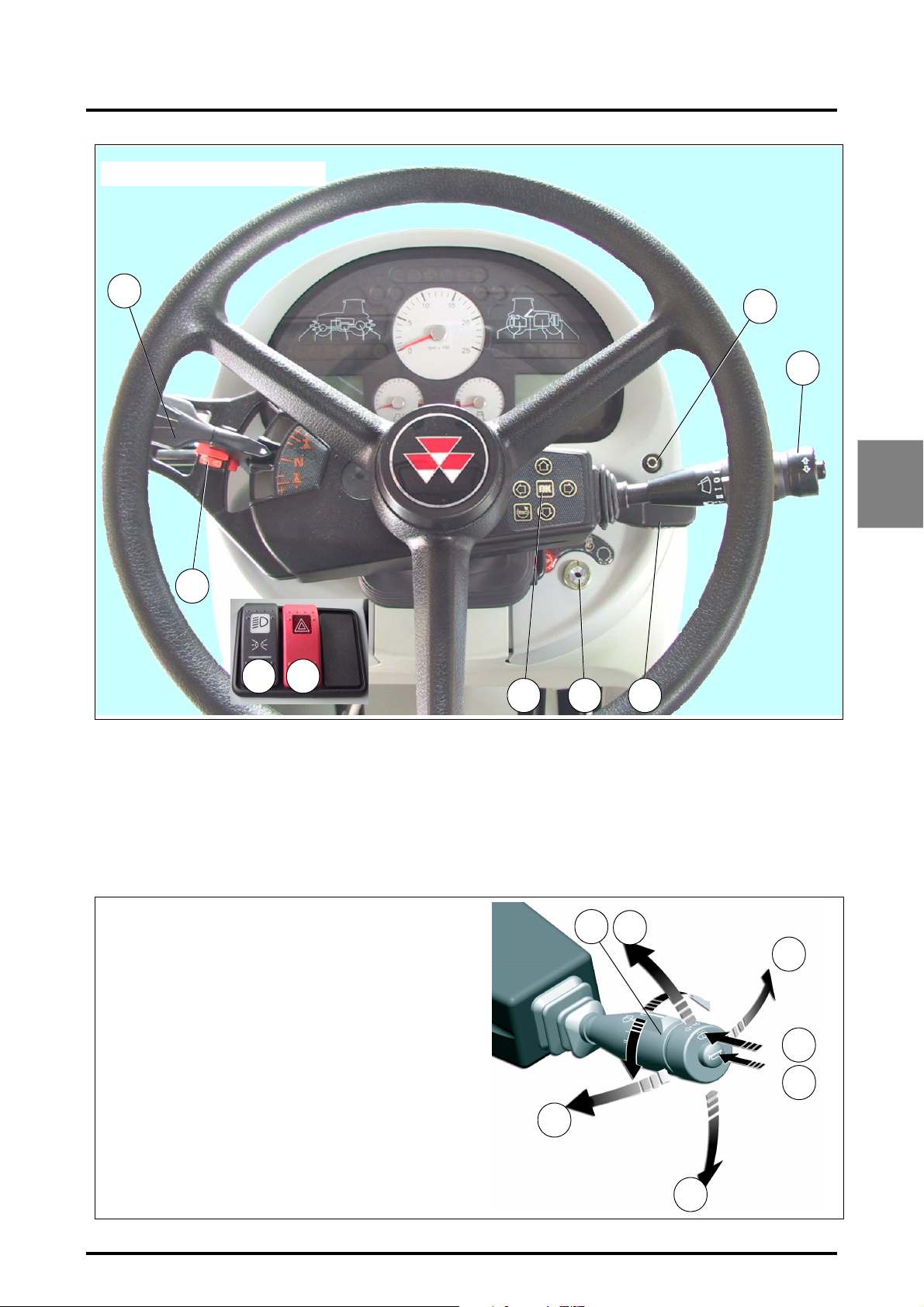
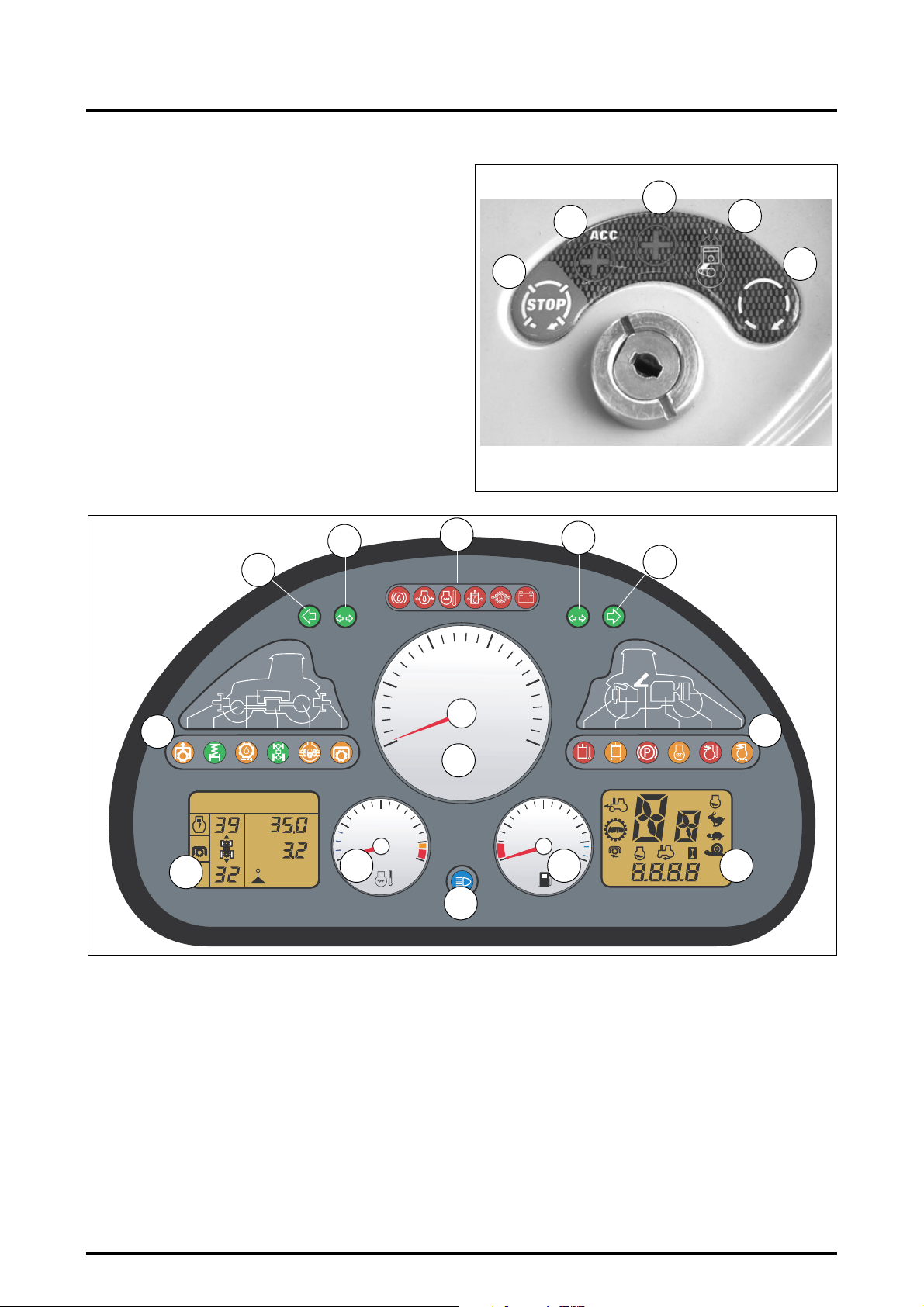
3.1 - INSTRUMENT PANEL (FIG. 1)
1. Start switch (see details in Fig. 3).
2. Control unit (see details in Fig. 2).
This assembly is comprised of the steering change,
windscreen wiper, front and rear windscreen washer
and horn indicator functions.
Legend:
1. Windscreen wiper
-0. Stop
- J. Intermittent
- I. Speed 1
- II. Speed 2
2. Left-hand direction indicator
3. Right-hand direction indicator
4. Warning buzzer
5. Headlights flash
6. Headlights
7. Rear and front windscreen washer
3. Steering wheel adjustment (see details in Fig. 23).
4. DOT MATRIX controls (see details in Fig. 10).
5. Parameter display selector switch (21 Fig. 4).
6. Main light switch.
7. Hazard warning lights and control switch.
8. Direction of travel and PowerShuttle control lever.
9. Electromechanical brake control (ParkLock option).
1
5
2
7
4
3
Z2-187-B
6
Fig. 2
8400 EAME
3.5
Page 40
3 . INSTRUMENTS AND CONTROLS
2
Start switch details (Fig. 3):
1. Stop
2. Contact position for electrical equipment to be
used when the engine is not running.
3. Contact position for electrical equipment used
when the engine is running.
4. Preheating (wait for instrument panel indicator
lights to switch off).
5. Start-up
NOTE: The tractor runs with the key in position (3); to
fully disconnect all electrical equipment, the key must
be moved back through the accessory position (2) to
the stop position (1).
Z2-005
3
2
1
4
5
Fig. 3
INSTRUMENT PANEL
17
14
1
10
5
19
S
1
..
..
AUTO
AUTO
22
Z3A-993-08-04
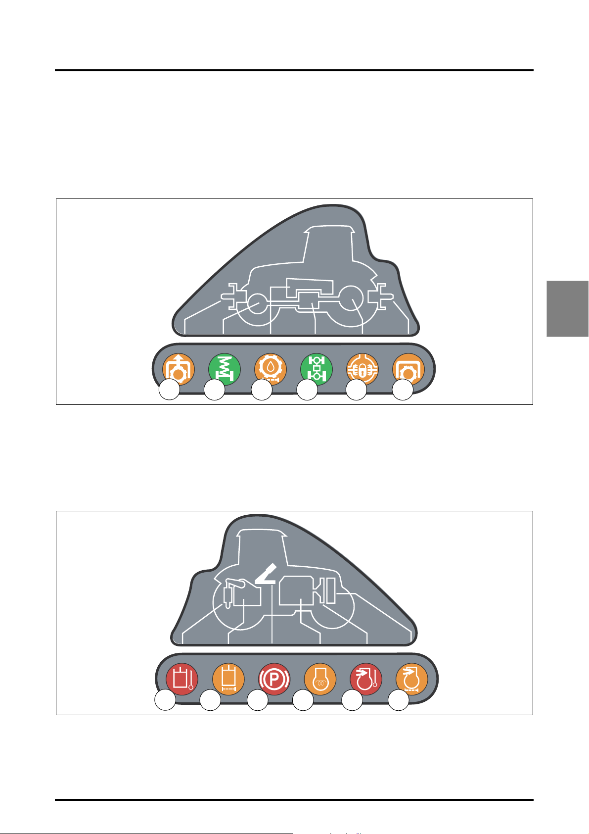
Instrument panel (Fig. 4)
10. Tachometer
The tachometer shows the engine speed in hundreds
of revolutions per minute.
11. Fuel gauge.
12. Engine coolant temperature gauge.
Stop the engine if the needle moves into the red zone.
13. Right-hand direction indicator light (green).
14. Left-hand direction indicator light (green).
15. Failure warning lights unit.
See details (Fig. 7)
16. Headlight indicator light (blue).
17. Direction indicator light for the first trailer (green).
18. Direction indicator light for the second trailer (green).
v
S
2
.
.
v
.
.
12
0
RPM x 100
15
18
13
2
15
20
20
10
25
AAB
AAB
KPH
11
540
1000
ECO
KPH
MPH
MPH
RPM
RPM
21
16
19. Control indicator lights for functions in use (see
details in Fig. 5).
20. Failure and parking brake control indicator lights (see
details in Fig. 6).
if one of the indicator lights remains lit after the engine
has started or during normal use, stop the engine and
investigate the cause of the problem.
21. Digital display
Displays the speed engaged (forward / reverse), A/B
memory (electronic injection engine), Hare / Tortoise
range.
22. DOT MATRIX screen (see details in Fig. 10).
Fig. 4
3.6
8400 EAME
Page 41
3 . INSTRUMENTS AND CONTROLS
3.2 - INDICATOR LIGHTS PANEL
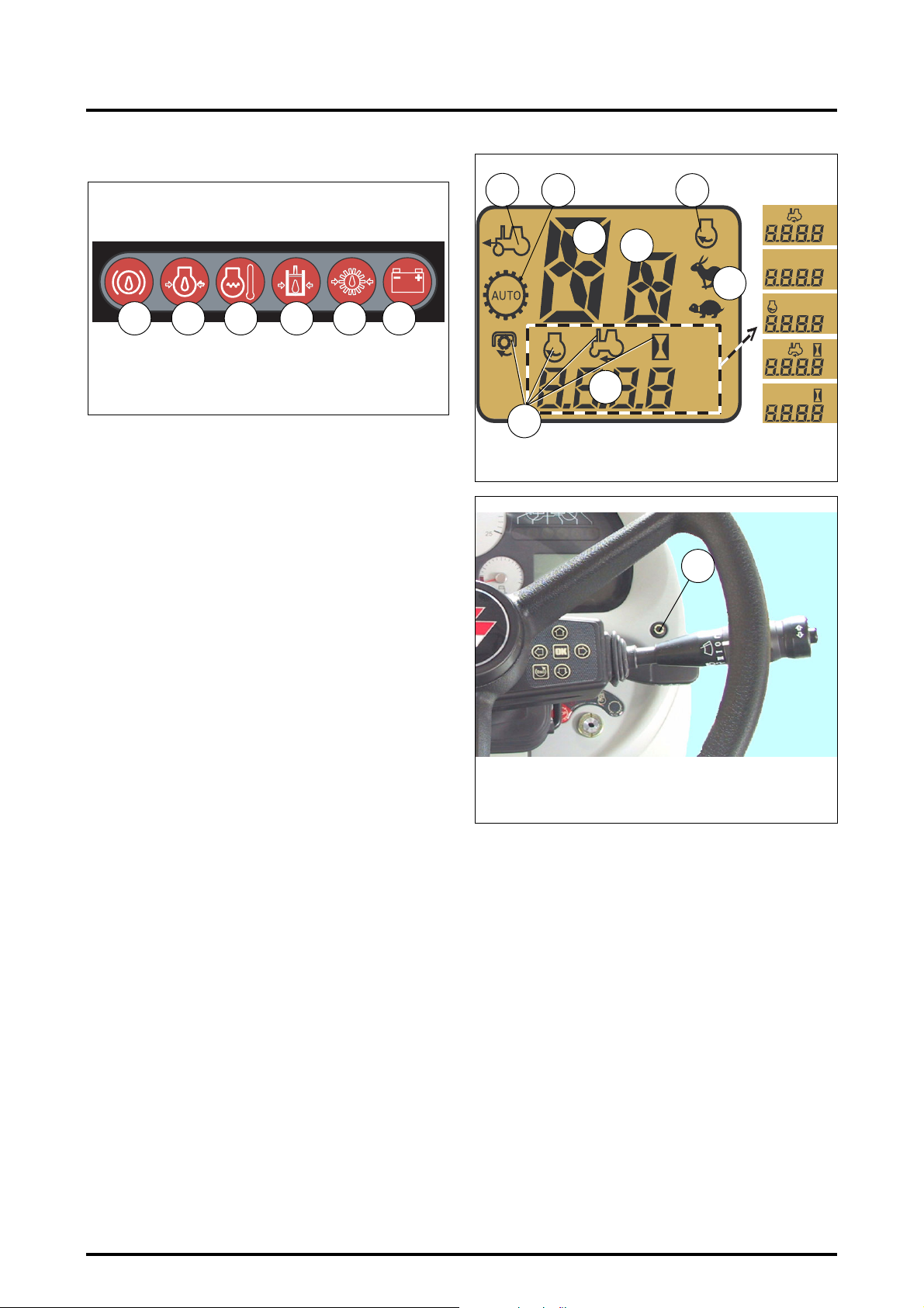
3.2.1 - Control indicator lights for functions in use (Fig. 5)
Green and orange control indicator lights display and monitor the functioning of attachments and implements.
1. Front power take-off (
2. Front axle suspension indicator light (green) (if option
fitted).
orange
).
3. High pressure transmission oil filter clogging indicator
light (yellow).
4. Four-Wheel-Drive engaged indicator light (green).
5. Differential lock indicator light (
6. Power take-off engaged (
orange
orange
).
).
3
Z3A-1139-10-04
3.2.2 - Failure and parking brake control indicator lights (Fig. 6)
Red control indicator lights signal problems of varying importance. They light up when the ignition key is turned in
the start switch and usually go out once the engine is running.
21
3 4
5
If they light up when the engine is running normally,
stop the engine at once and investigate the cause of the
problem.
7. Auxiliary hydraulics oil temperature indicator light
(red).
8. 15 micron auxiliary hydraulics oil filter clogging indicator light (
orange
6
).
Fig. 5
Z3A-1140-10-04
9. Parking brake indicator light (red)
10. Grid Heater indicator light (red).
11. Intake air temperature indicator light (red).
This indicator light is switched on when the ignition
key is in "auxiliary" position. It switches off when the
8400 EAME
87
9 10
11 12
engine starts running. If the indicator light comes on
when the engine is running, stop the engine and investigate the cause of the problem immediately.
12. Air filter clogging indicator light (
orange
).
Fig. 6
3.7
Page 42
3 . INSTRUMENTS AND CONTROLS
M
M
H
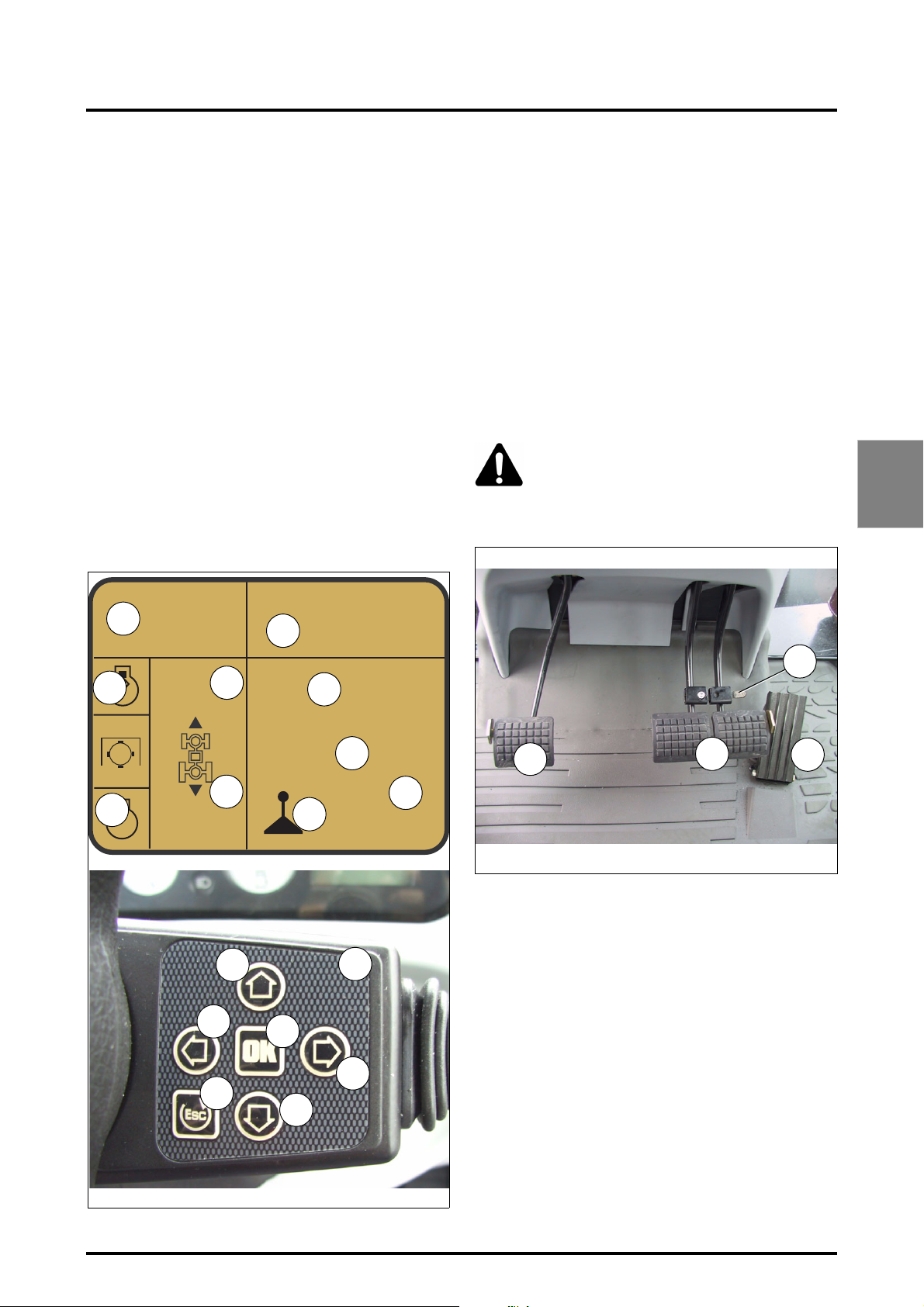
Failure control warning lights
13
Z3A-1138-10-04
13. "ParkLock" brake pressure indicator light (red).
14. Engine oil pressure indicator light (red).
This indicator light is switched on when the ignition
key is in "auxiliary" position. It switches off when the
engine starts running. If the indicator light comes on
when the engine is running, stop the engine and investigate the cause of the problem immediately.
Check for low oil level or consult your dealer.
15. Coolant temperature indicator light (red).
16. Not used.
17. Gearbox oil pressure indicator light (red).
If this warning light gets on during operation, consult
your agent or dealer.
18. Alternator charge indicator light (red).
14
15 16
17 18
Fig. 7
6
A
540
1000
ECO
Z3A-1459-06-05
5
1
2
A
7
B
KP
8
RP
RP
KPH
4
MPH
RPM
3
Fig. 8
5
3.3 - CONTROL DISPLAY
Fig. 8 - This control screen allows the different parameter
displays to be monitored:
1. Forward / neutral / reverse liquid crystal display.
2. Reverse shuttle sensitivity indicator.
3. Selected symbols display: rear PTO/engine speed/forward ground speed:
All parameters can be displayed in the lower part of the
screen and can be selected by pressing button 5 (Fig. 9)
located on the instrument panel.
4. Digital display: rear PTO speed, engine speed, ground
speed, hours worked.
NOTE: To reinitialise hours worked, select the relevant
parameter and hold the button 5 (Fig. 8) down for
approximately 5 seconds to reset the display.
5. Power take-off automation.
6. Front axle automatic functions monitor.
7. A/B speed (engine with electronic fuel injection) memorisation status.
8. Hare / Tortoise range engagement indicator lights.
Z3A-742-07-04
Fig. 9
3.8
8400 EAME
Page 43
3 . INSTRUMENTS AND CONTROLS
3.4 - DOT MATRIX SCREEN
Fig. 10 - This control screen allows the different parameter
displays to be monitored:
1. Programmed engine speed A
2. Programmed engine speed B
3. Programmed engine speed indicator
4. Engine underspeed supervisor
5. Forward shuttle speed value display
6. Reverse shuttle speed value display
7. Mode display (pedal, lever, etc.)
8. Selected mode speed display
9. SV1 speed regulator display
10. SV2 speed regulator display
11.
12. Control unit to access DOT MATRIX menus
13. Up scrolling key
14. Down scrolling key
15. Left-hand adjustment key
16. Right-hand adjustment key
17. Validation key
18. Cancel key
3.5 - PEDALS
(Fig. 11)
1. Clutch pedal.
This is fitted with a safety start switch. Fully depress
the clutch pedal before operating the starter.
NOTE: Do not keep the clutch pedal pressed fully or half
down.
2. Brake pedals.
The two brake pedals can either be used separately or
locked together using latch 3.
3. Brake pedals locking latch.
4. Foot throttle.
Use of the foot throttle enables a momentary increase
in the engine speed set by the hand throttle lever.
CAUTION: When travelling on the road only the
foot throttle should be used, and the hand throttle
lever should be brought to the idle position so that
engine braking can be operational.
Check that A/B memorised speed is not activated.
3
1
1055 800
4
AUTO
3
A/B
Z2-602-05-03
3.2
0.2
5
6
13
15
S
v
S
v
17
2
1
2
9
35.0
10
7
25.3
12
3.2
8
Z2-410-05-03-A
3
1
2
4
Fig. 11
Z3A-1202-10-04
8400 EAME
16
18
14
Fig. 10
3.9
Page 44
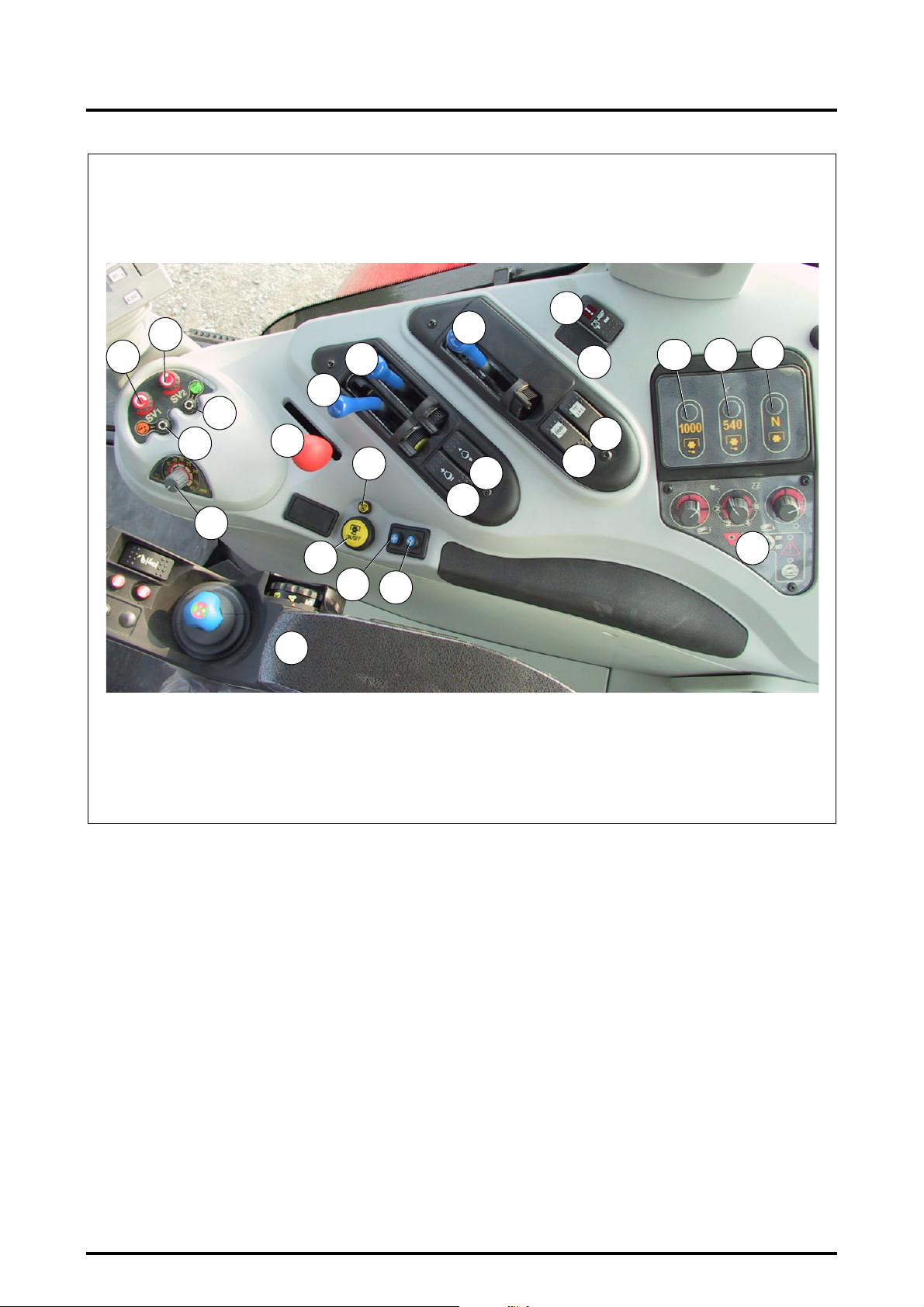
3 . INSTRUMENTS AND CONTROLS
7
6
5
4
1
2
9
8
19
18
23
10
22
13
12
14
11
15
16
17
3
21
20
24
Z3A-771-07-04
3.6 - RIGHT-HAND CONSOLE
(Fig. 12)
1. Hand throttle lever
2. Engine underspeed supervisor
3. Electronic linkage controls
4. Lever or pedal mode button
5. Hare / Tortoise range button
6. SV1 speed regulator display knob
7. SV2 speed regulator display knob
8. Third Auxiliary Spool valve lever
9. Fourth Auxiliary Spool valve lever
10. Fifth Auxiliary Spool valve lever
11. 4WD switch
12. Differential lock switch
13. Cab suspension switch.
14. Front axle suspension switch (suspended front axle
option)
15. 1000 rpm PTO control switch
16. 540 rpm PTO switch
17. Neutral PTO switch
Fig. 12
18. 540 / 540E / 1000 rpm rear PTO ON/OFF switch
19. Rear power take-off selector switch in automatic mode
20. Spool valve control on / off button.
21. Spool valve hydraulic flow rate memory or cancel button
22. A/B speed switch
23. +/- engine speed switch after selecting A/B speed
24. Multi-function armrest
3.10
8400 EAME
Page 45
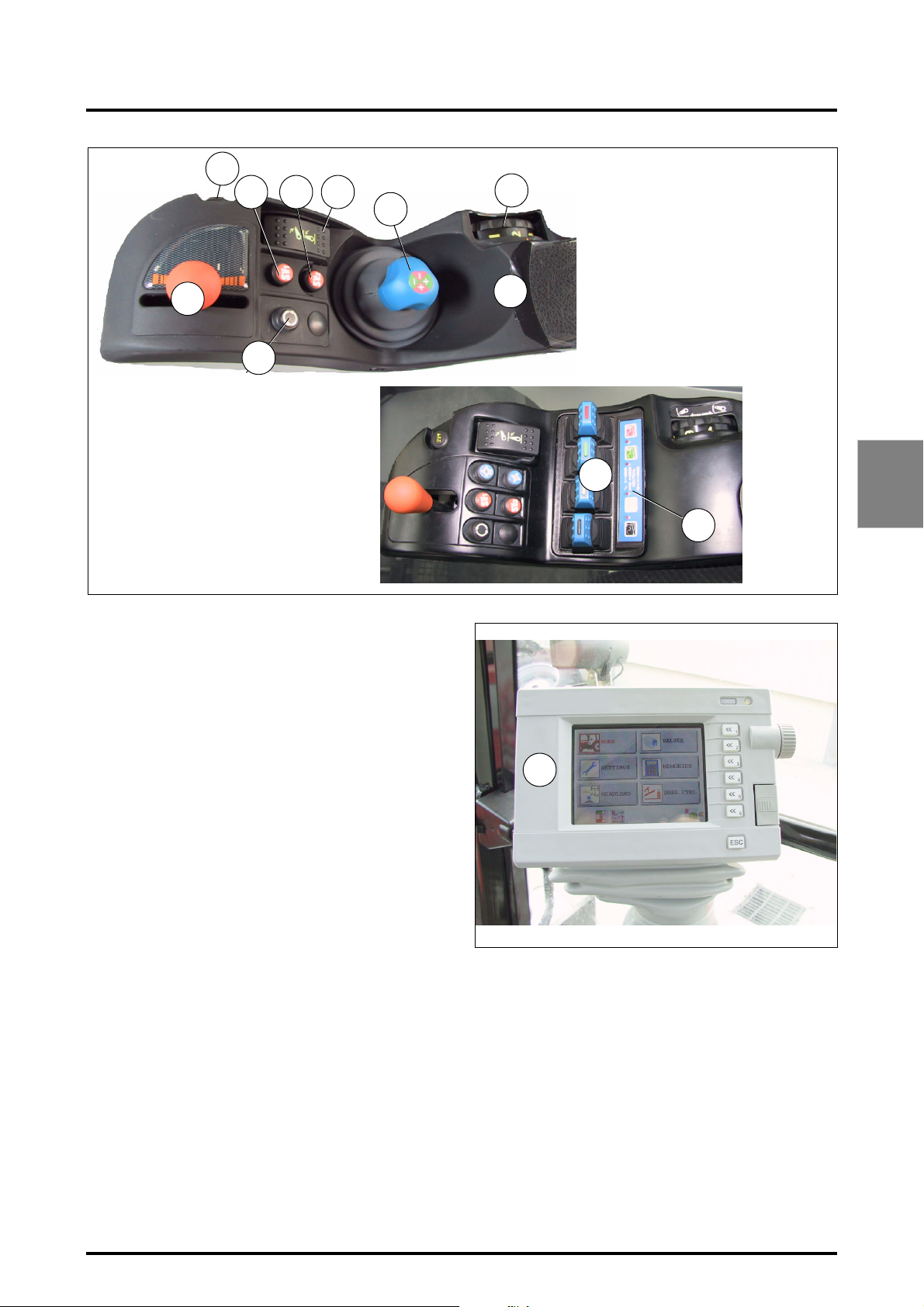
32
29
28
27
3 . INSTRUMENTS AND CONTROLS
26
25
30
31
Z3A-706-07-04
Z3A-1502-11-04
25. 4-function control Joystick (separate or combined).
(Fig. 13).
26. Height / depth setting knob.
27. Lift / Lower selector switch with “neutral” position
28. SV1 speed regulator control knob
29. SV2 speed regulator control knob
30. Transmission progressivity control
31. HEADLAND mode control knob (DATATRONIC 3
Headland option)
32. Quick soil engagement control switch
33. Four "SMS" spool valve controls ("FingerTIP" option)
(Fig. 13), (see section 4.14.8).
34. Spool valve constant flow position switches (Kick out)
(see section 4.14.8)
35. Datatronic 3 onboard computer (Fig. 14).
24
35
33
3
34
Fig. 13
8400 EAME
Z3A-772-07-04
Fig. 14
3.11
Page 46
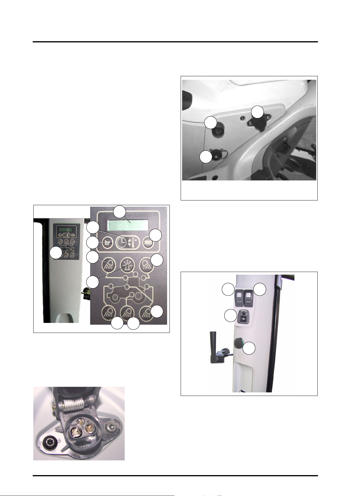
3 . INSTRUMENTS AND CONTROLS
36. Work headlights/digital clock/temperature sensor control and indicator lights.
Work headlights: Press the key(s) 1 to 6 (Fig. 15) to
operate de desired function(s). The corresponding indicator light will come on:
1. Front work headlights
2. Work headlights on footsteps and handrails.
3. Work headlights on fenders
4. Work headlights on front of roof
5. Flashing beacon
6. Work headlights at rear of roof
7. Digital clock and temperature sensor:
Press button A to select and change the time or
temperature display.
Adjusting the clock: to change the time press buttons B or C to select the information (hr or min.) to
be changed.
Temperature control: Press button A to select the
outside temperature display. To change from °Celsius to °Fahrenheit press button A for approximately 5 seconds.
Z2-413-05-03
7
A
C
B
36
4
6
38. Diagnostics connector.
39. Cigarette lighter.
37
39
38
Z2-415-05-03
Fig. 16
3.7 - LEFT-HAND CONSOLE
(Fig. 17, Fig. 18)
40. Cigarette lighter type connector.
41. Electrical control for external rear view mirrors
(optional).
42. Rear windscreen wiper.
43. Rear view mirror defrosting control (optional).
5
3
1
Z3A-743-07-04
37. Electrical connector for control screens, control units
and other (Fig. 16).
Maximum available power:
15/30: "+" Permanently live (25 A).
82: "+" with ignition key ON (5 A).
31: "-" negative.
2
Fig. 15
42
41
Z2-613-05-03
44. Emergency handbrake.
45. Instructor seat (optional).
46. Storage bin
47. Can carrier.
43
40
Fig. 17
3.12
Z3A-401-12-04
8400 EAME
Page 47
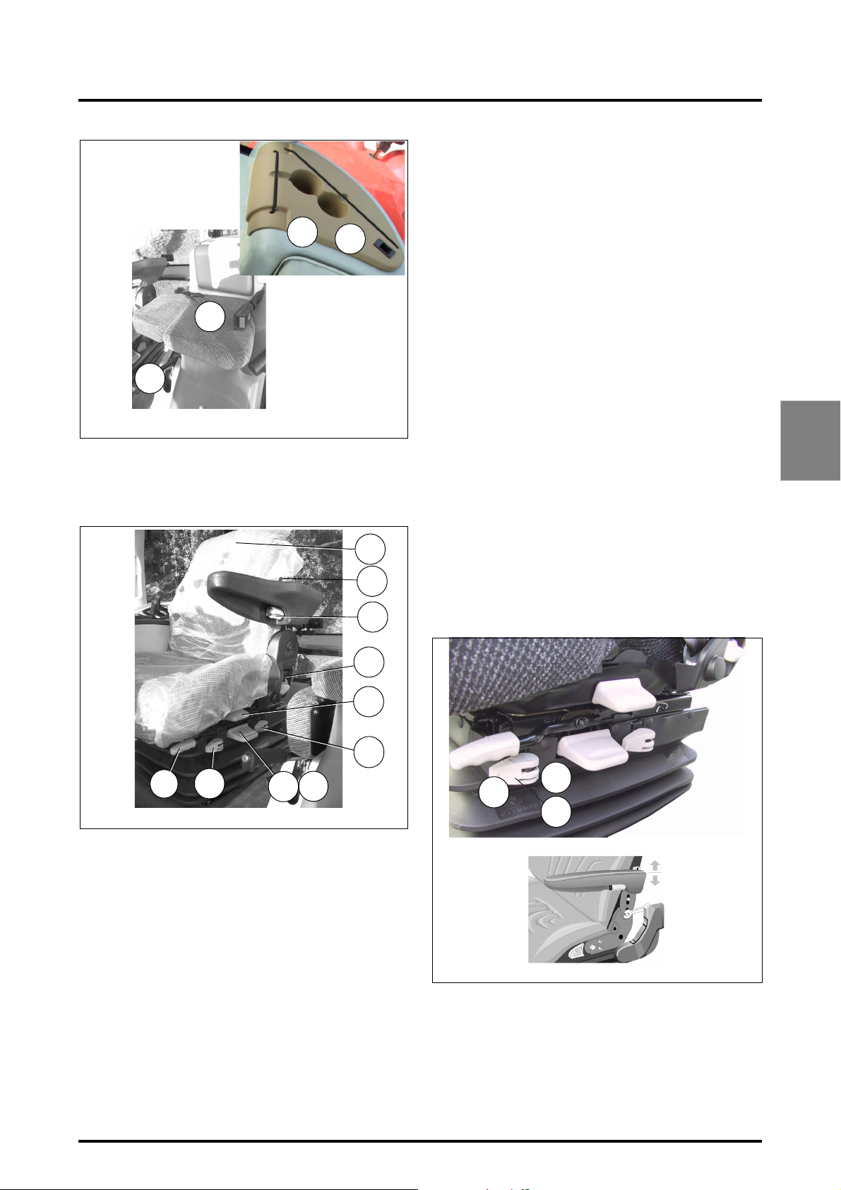
44
Z2-418-05-03
3.8 - SEAT
45
47
46
Z2-417-05-03
Fig. 18
3 . INSTRUMENTS AND CONTROLS
The seat height can be altered by either pulling out or
pushing in the actuator lever of the automatic weight
and height actuator lever (2). If the adjustment reaches
the top or bottom endstop, the height is adjusted automatically in order to guarantee a minimum spring
travel.
NOTE: In order to avoid damage, do not operate compressor for more than 1 minute.
Manual adjustment seat
The seat height can be set automatically and is adjustable in several steps. The seat can be raised as required
until it clicks into position. If the seat is raised higher
than the last notch (end of travel), it returns to its lowest position.
3. Fore / aft adjustment:
The locking lever must latch into the desired position.
It should not be possible to move the driver seat into
another position when it is locked.
4. Backrest angle adjustment.
5. Swivel adjustment:
Pull the lever until you feel resistance which allows
you to turn the seat 20° to the left and 10° to the right.
Lockable every 10°.
If you pull more strongly to overcome the resistance
the swivel is unlocked and you can turn freely. For
6
7
9
locking push back lever again.
The locking lever must latch audibly into place. The
swivel should be in the central position for driving.
6. Backrest extension.
7. Lumbar support adjustment.
3
4
5
10
3
Z2-419-05-03
Description (Fig. 19)
1. Weight adjustment:
Automatic pneumatic seat
The seat is adjusted for the driver's weight by briefly
pulling the weight and seat height automatic actuator
lever (1) while the driver is sitting on the seat.
Manual adjustment seat
The seat should be adjusted when the driver is not
seated by turning the actuator lever (or adjustment
thumb wheel) provided for this purpose. The indicator
displays the weight which has been set.
NOTE: To prevent damage to the health, the setting for
the driver's weight must be checked and adjusted as
necessary before the vehicle is driven.
2. Height adjustment:
Automatic pneumatic seat
The seat height can be set automatically and continuously.
8
2
1
Fig. 19
2
1
8
Z3A-916-08-04
V721a
8. Fore / aft isolator (Fig. 20):
Under certain driving conditions (for example with a
trailer attached), it is useful to activate the fore / aft isolator. This means that shock impacts in the driving
direction can be better absorbed by the driver seat:
- Position 1 = fore / aft isolator on
- Position 2 = fore / aft isolator off.
Fig. 20
8400 EAME
3.13
Page 48
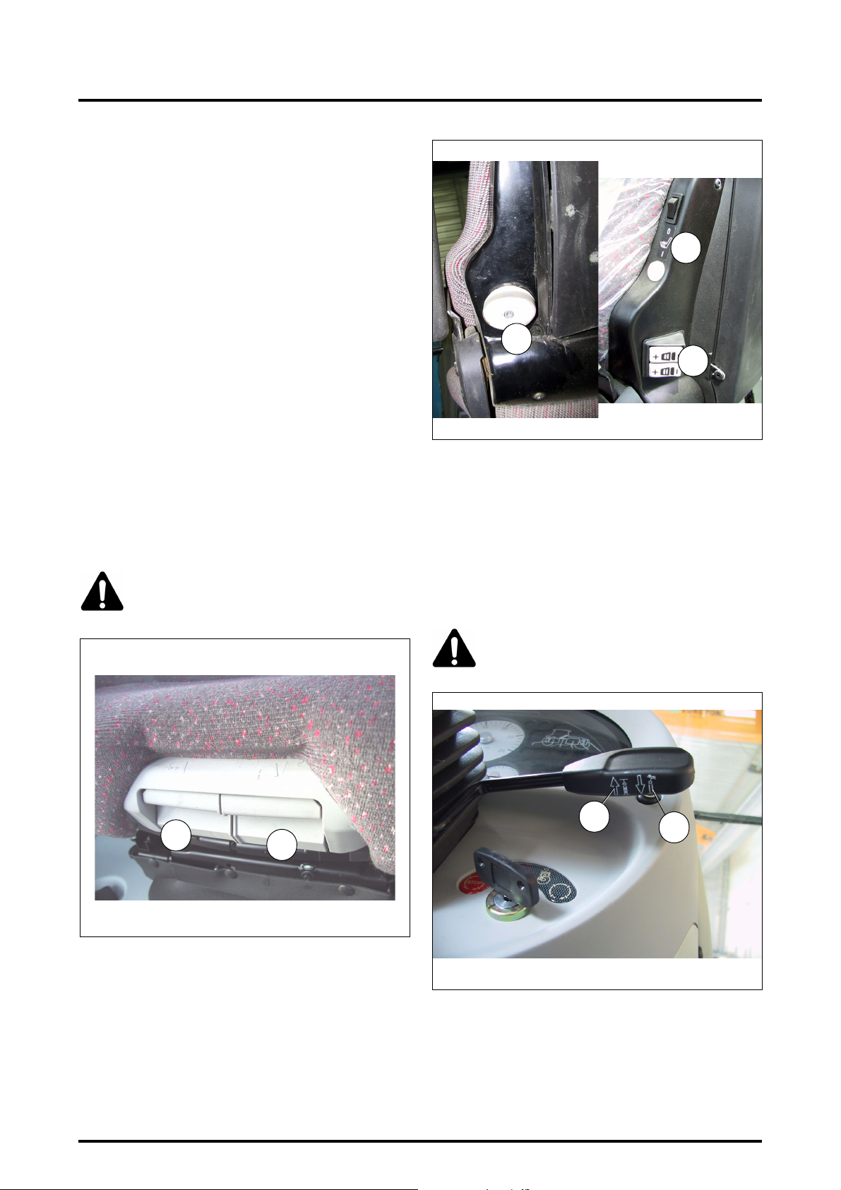
3 . INSTRUMENTS AND CONTROLS
9. Armrest angle adjustment:
The armrests can be folded up if required and the
height individually adjusted.
To adjust the armrest height (arrows) the plastic cover
must be removed by pressing together the inner clips
and pulling off the cover at the same time.
The cover is refitted in the same way in reverse order.
10. Height/weight adjustment indicator.
Luxury pneumatic seat with automatic adjustment
11. Seat pan angle adjustment:
The angle of the seat pan can be individually adjusted.
Pull on the left-hand button (see diagram) while exerting or releasing pressure on the seat pan in order to
find a comfortable position.
12. Seat depth adjustment:
The depth of the seat pan can be individually adjusted.
Pull on the right-hand knob (see diagram) and move
the seat forwards or backwards to find the required
position.
13. Lumbar support adjustment:
Turn the handle to the left or right to move the lumbar
support vertically or horizontally.
14. Seat heater:
The seat heater is turned on by pressing the switch.
WARNING: Never adjust the seat when tractor is in motion.
14
13
13
Z2-199
Z2-197
Fig. 22
3.9 - STEERING WHEEL
(Fig. 23)
The steering wheel angle and height can be adjusted (ex-
cept platform versions). Both adjustments are made by a
single lever.
1. Height adjustment
2. Angle adjustment
Z2-348-01-04
12
11
Fig. 21
Z3A-744-07-04
DANGER: Adjustments of the steering wheel
must be done with the tractor stopped.
1
2
Fig. 23
3.14
8400 EAME
Page 49
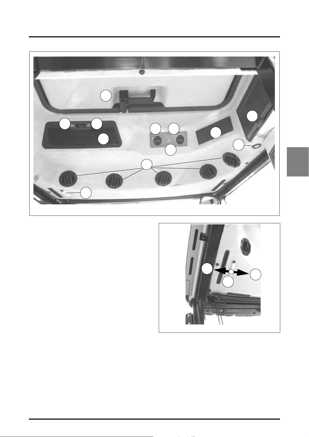
3 . INSTRUMENTS AND CONTROLS
10
7
A
B
3
4
6
2
9
5
8
1
Z2-425-05-03
3.10 - UPPER CONSOLE
(Fig. 25)
1. Interior light (Fig. 25).
By rotating the 3-position switch:
0 - off position.
1 - light comes on when opening the left hand door.
2 - permanently on.
2. Adjustable ventilation grille (depending on model).
A: Outside air intake
B: Recycling
3. 4-speed ventilator/heater fan control (if fitted).
4. Heater controls:
Blue = cold
Red = warm
5. Automatic air conditioning system control (optional).
6. Radio (if fitted).
7. Drink storage compartment, which is cooled when the
tractor is equipped with air conditioning.
8. Adjustable air circulation vents.
9. Lighting of console.
10. Roof hatch (optional).
Z2-426-05-03
3
Fig. 24
2
1
0
Fig. 25
8400 EAME
3.15
Page 50
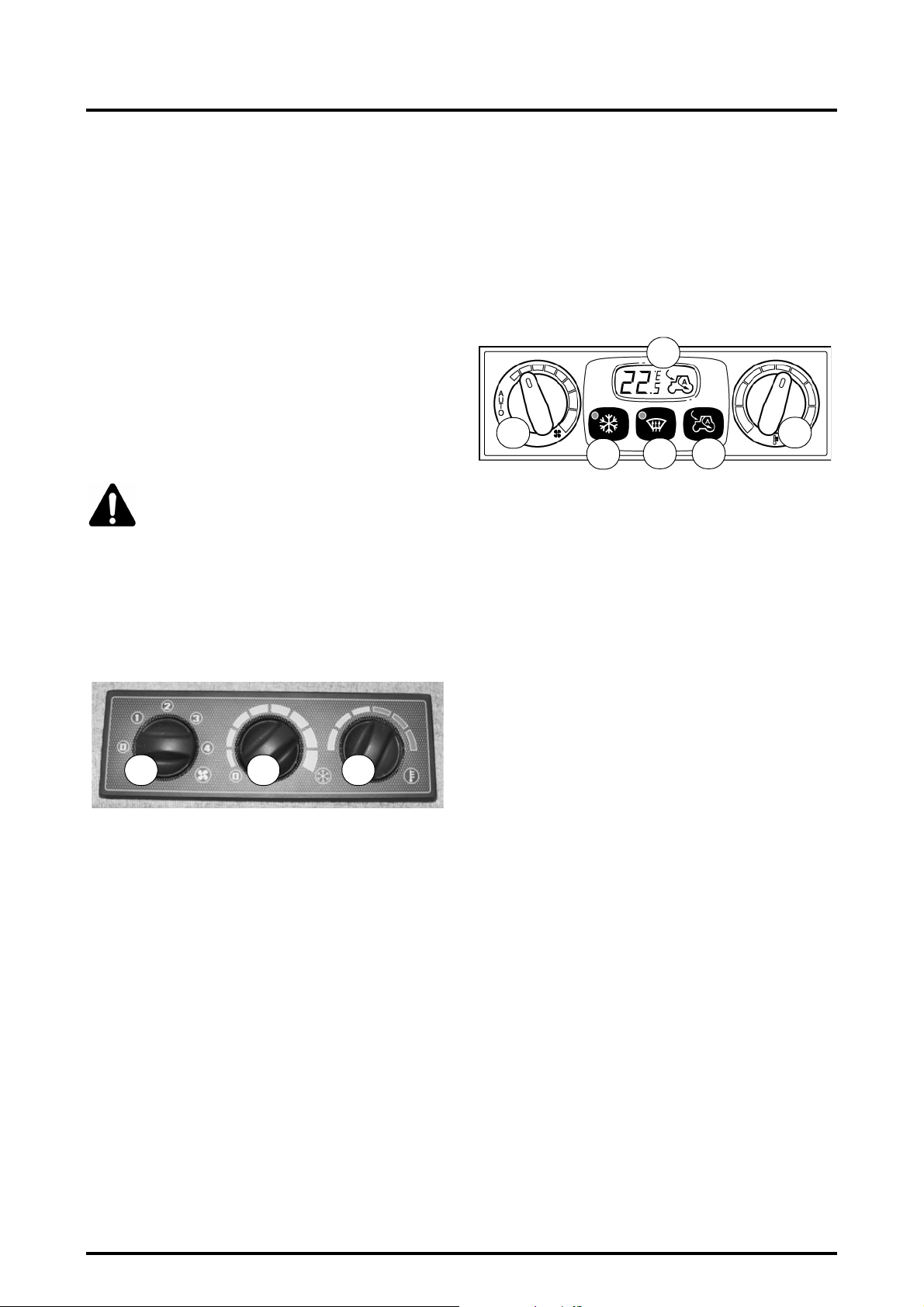
3 . INSTRUMENTS AND CONTROLS
3.10.1 - Air conditioning system
IMPORTANT: When the air conditioning system is in
use the cab doors and windows should be closed. Do
not use the air conditioning system when the temperature falls below 20°C (68°F). Switch off the system
before starting up the engine. Ensure the cab air filter is
clean (see chapter 5).
NOTE: If the air conditioning has not been used for
some time, unlock the compressor before starting the
engine, by rotating the pulley nut with a wrench.
IMPORTANT: To prevent seizure of the compressor and
keep the cooling system in good condition, operate the
air conditioning for a few minutes at least once a week
even in winter.
ONCE A YEAR HAVE THE CIRCUIT CHECKED BY YOUR
DEALER.
WARNING: Do not attempt to disassemble
any part of the air conditioning system.
3.10.2 - Manual air conditioning system
3.10.2.1 - Description
1. Manual ventilation control knob
2. Thermostat (minimum / maximum) control knob
3. Heating (minimum/maximum) control knob
1
Z2-427-05-03
3.10.2.2 - Operation
1. When the engine is running, turn knob 3 to the left
(cold) and move knob 2 to minimum position.
2. Position the fan 1 knob in fast position (fan symbol
side).
3. When the required cab temperature is obtained, adjust
the heating knob and rotate knob 2 if required to maintain a comfortable temperature.
4. Reduce the speed of fan 1 with the knob 3 to obtain a
comfortable temperature.
2
3
Air conditioning stop: reset the fan knob 1 and temperature
switch knob 2 to zero to stop the air conditioning.
NOTE: If a low fan speed and a low temperature are
used for long periods, the evaporator may start to ice
up. If icing occurs, adjust the temperature control knob
to raise the temperature, and if the icing continues,
increase the fan speed.
3.10.3 - Automatic air conditioning system (optional)
2
1
Z2-428-05-03
3.10.3.1 - Description
1. Manual/automatic fan control knob
2. Digital display (LCD)
3. Compressor ON/OFF button
4. Defrosting button
5. Recycling button
6. Temperature control knob
3.10.3.2 - General characteristics
The temperature inside the cab is controlled automatically
by the air conditioning system that controls the temperature at the air vents, the fan speed, recycling and the compressor operation.
The required temperature can vary by 0.5°C (1°F) between
20-24°C (68-76°F) and by 1°C (2°F) outside this temperature range.
Scale of Celcius and Farenheit temperatures:
°C - LO/18/19/20/20.5/21/21.5/22/22.5/23 23.5/24/25/26/
27/28/HI
°F - LO/64/66/68/69/70/71/72/73/74/75/76/78/80/82/84/HI
The HI and LO displays and tractor icon indicate the recycling function status.
3.10.3.3 - Operation when the engine is stopped
When the tractor is started, all manual interventions carried
out before stopping the vehicle are stored and are suggested at successive startings, except for the defrosting function.
3
4 5
6
3.16
8400 EAME
Page 51
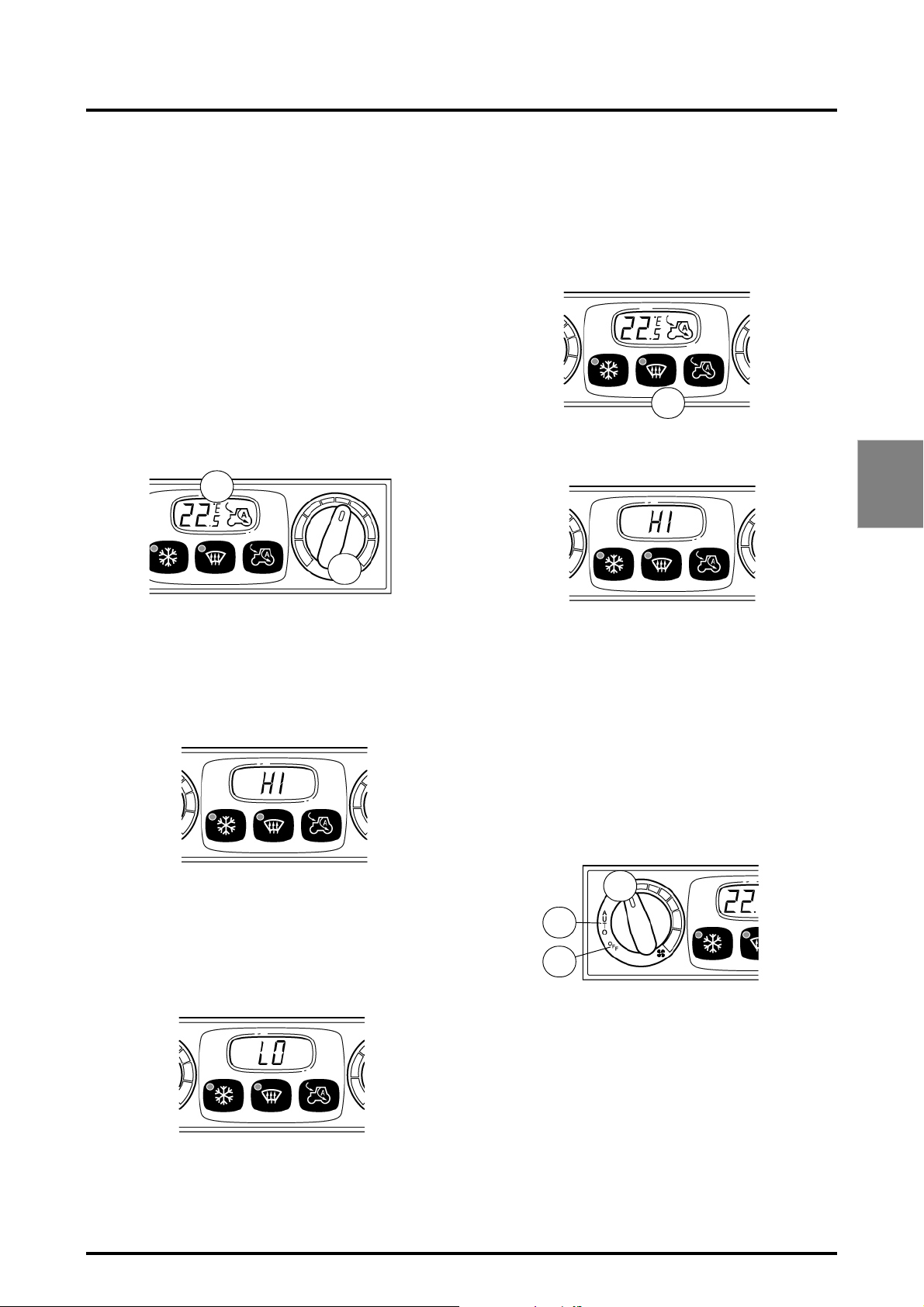
3 . INSTRUMENTS AND CONTROLS
3.10.3.4 - Preselecting the cab temperature
Preselect the required temperature with knob 6. The preselected value is displayed on the LCD screen (2).
To change the display from Celsius to Fahrenheit:
• Switch off the ignition key.
• Move the fan switch 1 to OFF position.
• Move temperature knob 6 to maximum heat position
(red)
• Switch on ignition key and within 5 seconds press the
defrosting button 4 and air recycling button 5 simultaneously.
• The temperature symbol (°C or °F) will appear on the
LCD screen.
When there is a problem or error, an "E" is displayed to
warn the user (contact your dealer to determine the cause
of the problem).
2
6
Z2-429-05-03
3.10.3.7 - Defrosting function
This function is activated by pressing button 4 (approximate time: 3 minutes).
The relevant indicator light comes on.
To switch off the defrost option and return to the previous
condition, press the defrost switch again (the LED 4 is
switched off), or once the 3 minutes have passed.
Z2-432-05-03
The compressor is activated (A/C LED is lit)
- HI is displayed on the LCD screen.
Z2-433-05-03
4
3
3.10.3.5 - Maximum temperature
To reach maximum temperature, adjust the cab temperature gauge to over 28°C.
Air conditioning is ON (A/C LED is lit)
- HI is displayed on the LCD screen.
Z2-430-05-03
3.10.3.6 - Minimum temperature
To reach minimum temperature, adjust the cab temperature gauge to under 18°C.
Activating the compressor (A/C LED is lit)
- LO is displayed on the LCD screen.
3.10.3.8 - Air flow adjustment
When fan control knob 1 is in auto position (A), air flow is
selected automatically. Air flow change is gradual.
It is possible to manually select an air flow different to the
air flow selected automatically. When the knob position is
changed, air flow change is instantaneous.
Depending on the level of solar radiation, the air flow adjusts automatically if the required temperature is lower
than the outside temperature, and the LCD temperature
display flashes.
Air flow can be adjusted to maintain the temperature inside
the cab at preselected levels.
1
A
B
Z2-434-05-03
Stopping the automatic function
Move the fan button 1 to the OFF position (B).
8400 EAME
Z2-431-05-03
3.17
Page 52
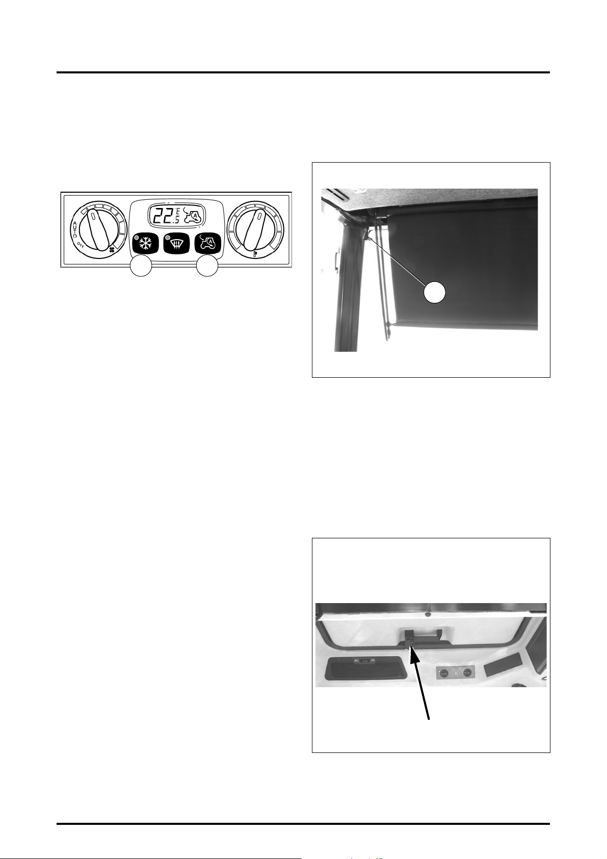
3 . INSTRUMENTS AND CONTROLS
3.10.3.9 - Air conditioning button
The tractor icon on the LCD screen indicates the recycling
function selected by the button 3 and the corresponding indicator light comes on when the compressor is used.
When recycling is in ON position, the air conditioning unit
is normally on, and can be switched off by pressing the button 3.
Z2-435-05-03
3.10.3.10 - Air recycling (ref. 5)
Recycling is in automatic mode and varies depending on
the external temperature.
If the Recycling button 5 is pressed once (ON position) an
arrow is displayed inside the tractor icon on the LCD
screen.
If the Recycling button 5 is pressed twice (OFF position) an
arrow is displayed outside the tractor icon on the LCD
screen.
If the Recycling button 5 is pressed a third time, automatic
control is restored and the letter A (automatic) appears in
the tractor icon.
Each time the unit is activated, if the external temperature
is higher than a pre-determined level, before overriding the
recycling function wait 2 minutes to change the air inside
the cab.
NOTE: If external temperatures are high, it is advisable
to work with the system in Recycling mode, with control knob 1 in automatic position.
3
5
3.11 - SUN VISOR
(Fig. 26)
To adjust the visor pull vertically down to desired position.
To raise visor pull cord (1).
1
Z2-436-05-03.
Fig. 26
3.12 - ROOF HATCH
(optional, Fig. 27)
This hatch is normally used to ventilate the cab.
The hatch is opened by pressing the button located on the
handle and pushing the hatch upwards.
To fully open the hatch (emegency exit), push hard on the
handle to force the gas cylinders from their holders. To
close the hatch, pull it downwards to engage the ends of
the gas cylinder rods in the supports, and continue pulling
the hatch downwards until it clicks into locked position.
3.18
Z2-356-01-04
Fig. 27
8400 EAME
Page 53
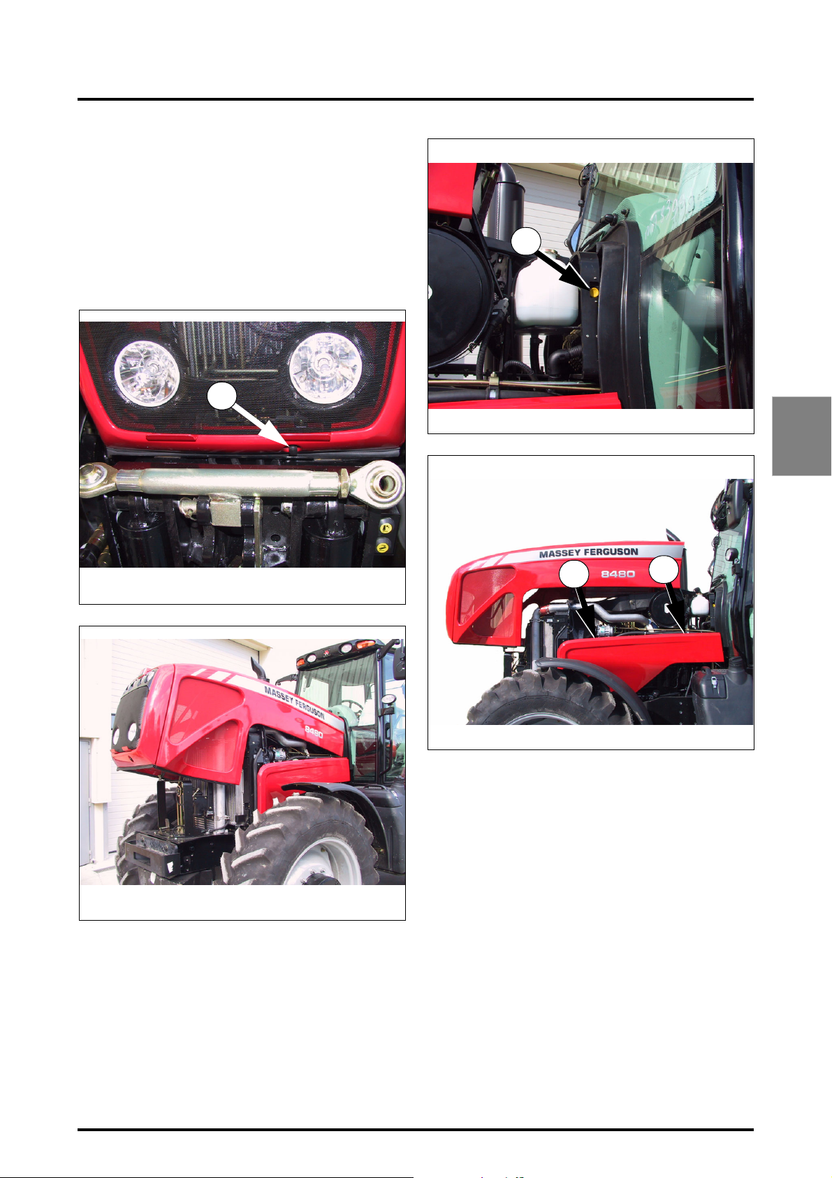
3.13 - BODY
The bonnet can be raised to allow free access to the engine.
To open it, press the button (ref. A Fig. 28) and lift the bonnet.
To fully open it, push the locking lever (ref. B Fig. 30) located to the rear of the bonnet.
To remove the side panel of the body, pull it at the points
indicated (C and D Fig. 31) and lift the panel to release it.
A
3 . INSTRUMENTS AND CONTROLS
B
Z3A-747-07-04
Fig. 30
3
Z3A-745-07-04
Z3A-746-07-04
Fig. 28
Fig. 29
Z3A-748-07-04
C
D
Fig. 31
8400 EAME
3.19
Page 54

Page 55

Chapter 4
4 . OPERATION
OPERATION
4
8400 EAME
4.1
Page 56

Page 57

4 . OPERATION
CONTENTS
4.1 - RUNNING IN . . . . . . . . . . . . . . . . . . . . . . . . . . . . . . . . . . . . . . . . . . . . . . . . . . . . . . . . . . . . . . . . . . . . . . . . . . . .4.5
4.1.1 The following precautions should be taken during the running in period . . . . . . . . . . . . . . . . . . . . . . .4.5
4.2 - START-UP . . . . . . . . . . . . . . . . . . . . . . . . . . . . . . . . . . . . . . . . . . . . . . . . . . . . . . . . . . . . . . . . . . . . . . . . . . . . . .4.5
4.2.1 Starting the engine . . . . . . . . . . . . . . . . . . . . . . . . . . . . . . . . . . . . . . . . . . . . . . . . . . . . . . . . . . . . . . . .4.5
4.2.2 Cold weather starting . . . . . . . . . . . . . . . . . . . . . . . . . . . . . . . . . . . . . . . . . . . . . . . . . . . . . . . . . . . . . .4.5
4.3 - STOPPING THE ENGINE . . . . . . . . . . . . . . . . . . . . . . . . . . . . . . . . . . . . . . . . . . . . . . . . . . . . . . . . . . . . . . . . . . .4.7
4.4 - DRIVING THE TRACTOR . . . . . . . . . . . . . . . . . . . . . . . . . . . . . . . . . . . . . . . . . . . . . . . . . . . . . . . . . . . . . . . . . . .4.7
4.4.1 Foot throttle. . . . . . . . . . . . . . . . . . . . . . . . . . . . . . . . . . . . . . . . . . . . . . . . . . . . . . . . . . . . . . . . . . . . . .4.7
4.4.2 PowerShuttle control. . . . . . . . . . . . . . . . . . . . . . . . . . . . . . . . . . . . . . . . . . . . . . . . . . . . . . . . . . . . . . .4.7
4.4.3 "ParkLock" electromechanical operated brake (optional) . . . . . . . . . . . . . . . . . . . . . . . . . . . . . . . . . . . . 4.7
4.4.4 Selecting the correct gear ratio . . . . . . . . . . . . . . . . . . . . . . . . . . . . . . . . . . . . . . . . . . . . . . . . . . . . . . .4.7
4.4.5 Preselecting A / B memorised engine speeds . . . . . . . . . . . . . . . . . . . . . . . . . . . . . . . . . . . . . . . . . . .4.8
4.5 - DYNA VTTRANSMISSION . . . . . . . . . . . . . . . . . . . . . . . . . . . . . . . . . . . . . . . . . . . . . . . . . . . . . . . . . . . . . . . . .4.9
4.5.1 General . . . . . . . . . . . . . . . . . . . . . . . . . . . . . . . . . . . . . . . . . . . . . . . . . . . . . . . . . . . . . . . . . . . . . . . . .4.9
4.5.2 Use . . . . . . . . . . . . . . . . . . . . . . . . . . . . . . . . . . . . . . . . . . . . . . . . . . . . . . . . . . . . . . . . . . . . . . . . . . . .4.9
4.5.3 Different control modes . . . . . . . . . . . . . . . . . . . . . . . . . . . . . . . . . . . . . . . . . . . . . . . . . . . . . . . . . . . 4.10
4.5.4 Setting ground speed . . . . . . . . . . . . . . . . . . . . . . . . . . . . . . . . . . . . . . . . . . . . . . . . . . . . . . . . . . . . .4.11
4.5.5 Selecting Hare or Tortoise range . . . . . . . . . . . . . . . . . . . . . . . . . . . . . . . . . . . . . . . . . . . . . . . . . . . . .4.12
4.5.6 SV1 and SV2 Speed regulators . . . . . . . . . . . . . . . . . . . . . . . . . . . . . . . . . . . . . . . . . . . . . . . . . . . . . .4.12
4.5.7 Engine underspeed supervisor . . . . . . . . . . . . . . . . . . . . . . . . . . . . . . . . . . . . . . . . . . . . . . . . . . . . . .4.13
4.5.8 Clutch-coupler function . . . . . . . . . . . . . . . . . . . . . . . . . . . . . . . . . . . . . . . . . . . . . . . . . . . . . . . . . . . .4.14
4.5.9 Setting restart speeds for shifting . . . . . . . . . . . . . . . . . . . . . . . . . . . . . . . . . . . . . . . . . . . . . . . . . . . .4.15
4.5.10 Using the DOT MATRIX screen. . . . . . . . . . . . . . . . . . . . . . . . . . . . . . . . . . . . . . . . . . . . . . . . . . . . . .4.15
4
4.6 - BRAKES . . . . . . . . . . . . . . . . . . . . . . . . . . . . . . . . . . . . . . . . . . . . . . . . . . . . . . . . . . . . . . . . . . . . . . . . . . . . . . .4.20
4.7 - DIFFERENTIAL LOCK. . . . . . . . . . . . . . . . . . . . . . . . . . . . . . . . . . . . . . . . . . . . . . . . . . . . . . . . . . . . . . . . . . . . .4.20
4.8 - FOUR WHEEL DRIVE . . . . . . . . . . . . . . . . . . . . . . . . . . . . . . . . . . . . . . . . . . . . . . . . . . . . . . . . . . . . . . . . . . . . .4.21
4.8.1 Suspended front axle. . . . . . . . . . . . . . . . . . . . . . . . . . . . . . . . . . . . . . . . . . . . . . . . . . . . . . . . . . . . . .4.21
4.9 - SUSPENDED CAB . . . . . . . . . . . . . . . . . . . . . . . . . . . . . . . . . . . . . . . . . . . . . . . . . . . . . . . . . . . . . . . . . . . . . . .4.22
4.10 - DIRECTION. . . . . . . . . . . . . . . . . . . . . . . . . . . . . . . . . . . . . . . . . . . . . . . . . . . . . . . . . . . . . . . . . . . . . . . . . . . . .4.22
4.11 - WHEEL SLIP CONTROL. . . . . . . . . . . . . . . . . . . . . . . . . . . . . . . . . . . . . . . . . . . . . . . . . . . . . . . . . . . . . . . . . . .4.22
4.12 - POWER TAKE-OFF. . . . . . . . . . . . . . . . . . . . . . . . . . . . . . . . . . . . . . . . . . . . . . . . . . . . . . . . . . . . . . . . . . . . . . .4.23
4.12.1 Rear power take-off. . . . . . . . . . . . . . . . . . . . . . . . . . . . . . . . . . . . . . . . . . . . . . . . . . . . . . . . . . . . . . . 4.23
4.12.2 External PTO stop button . . . . . . . . . . . . . . . . . . . . . . . . . . . . . . . . . . . . . . . . . . . . . . . . . . . . . . . . . .4.24
4.12.3 Interchangeable shaft end-fitting (flanged shaft) . . . . . . . . . . . . . . . . . . . . . . . . . . . . . . . . . . . . . . . . . 4.24
4.13 - ELECTRONIC LINKAGE . . . . . . . . . . . . . . . . . . . . . . . . . . . . . . . . . . . . . . . . . . . . . . . . . . . . . . . . . . . . . . . . . . .4.25
4.13.1 Attaching an implement from the driver’s seat . . . . . . . . . . . . . . . . . . . . . . . . . . . . . . . . . . . . . . . . . .4.26
4.13.2 Lowering . . . . . . . . . . . . . . . . . . . . . . . . . . . . . . . . . . . . . . . . . . . . . . . . . . . . . . . . . . . . . . . . . . . . . . . 4.26
4.13.3 Lifting. . . . . . . . . . . . . . . . . . . . . . . . . . . . . . . . . . . . . . . . . . . . . . . . . . . . . . . . . . . . . . . . . . . . . . . . . . 4.26
4.13.4 Depth control. . . . . . . . . . . . . . . . . . . . . . . . . . . . . . . . . . . . . . . . . . . . . . . . . . . . . . . . . . . . . . . . . . . .4.26
4.13.5 Attaching an implement using external controls . . . . . . . . . . . . . . . . . . . . . . . . . . . . . . . . . . . . . . . . .4.27
4.13.6 Transport . . . . . . . . . . . . . . . . . . . . . . . . . . . . . . . . . . . . . . . . . . . . . . . . . . . . . . . . . . . . . . . . . . . . . . .4.28
4.13.7 Activate transport control system . . . . . . . . . . . . . . . . . . . . . . . . . . . . . . . . . . . . . . . . . . . . . . . . . . . .4.28
4.13.8 Quick soil engagement . . . . . . . . . . . . . . . . . . . . . . . . . . . . . . . . . . . . . . . . . . . . . . . . . . . . . . . . . . . . 4.28
4.13.9 Use when working . . . . . . . . . . . . . . . . . . . . . . . . . . . . . . . . . . . . . . . . . . . . . . . . . . . . . . . . . . . . . . .4.28
4.13.10 Operation at headlands . . . . . . . . . . . . . . . . . . . . . . . . . . . . . . . . . . . . . . . . . . . . . . . . . . . . . . . . . . . .4.28
4.14 - AUXILIARY HYDRAULICS. . . . . . . . . . . . . . . . . . . . . . . . . . . . . . . . . . . . . . . . . . . . . . . . . . . . . . . . . . . . . . . . .4.29
4.14.1 General . . . . . . . . . . . . . . . . . . . . . . . . . . . . . . . . . . . . . . . . . . . . . . . . . . . . . . . . . . . . . . . . . . . . . . . .4.29
4.14.2 Hose connection . . . . . . . . . . . . . . . . . . . . . . . . . . . . . . . . . . . . . . . . . . . . . . . . . . . . . . . . . . . . . . . . .4.29
8400 EAME
4.3
Page 58

4 . OPERATION
4.14.3 Unlocking hydraulic spool valve controls . . . . . . . . . . . . . . . . . . . . . . . . . . . . . . . . . . . . . . . . . . . . . . .4.30
4.14.4 Using the control levers (Fig. 52). . . . . . . . . . . . . . . . . . . . . . . . . . . . . . . . . . . . . . . . . . . . . . . . . . . . .4.30
4.14.5 "SMS" controlled by Joystick . . . . . . . . . . . . . . . . . . . . . . . . . . . . . . . . . . . . . . . . . . . . . . . . . . . . . . . .4.32
4.14.6 Memorising a flow rate . . . . . . . . . . . . . . . . . . . . . . . . . . . . . . . . . . . . . . . . . . . . . . . . . . . . . . . . . . . .4.32
4.14.7 Setting joystick parameters . . . . . . . . . . . . . . . . . . . . . . . . . . . . . . . . . . . . . . . . . . . . . . . . . . . . . . . . .4.32
4.14.8 "SMS" control (FingerTIP). . . . . . . . . . . . . . . . . . . . . . . . . . . . . . . . . . . . . . . . . . . . . . . . . . . . . . . . . . .4.33
4.14.9 Emergency manual spool valve control . . . . . . . . . . . . . . . . . . . . . . . . . . . . . . . . . . . . . . . . . . . . . . . .4.33
4.15 - THREE-POINT LINKAGE . . . . . . . . . . . . . . . . . . . . . . . . . . . . . . . . . . . . . . . . . . . . . . . . . . . . . . . . . . . . . . . . . .4.34
4.15.1 Linkage . . . . . . . . . . . . . . . . . . . . . . . . . . . . . . . . . . . . . . . . . . . . . . . . . . . . . . . . . . . . . . . . . . . . . . . .4.34
4.15.2 Lower links . . . . . . . . . . . . . . . . . . . . . . . . . . . . . . . . . . . . . . . . . . . . . . . . . . . . . . . . . . . . . . . . . . . . . 4.34
4.15.3 Lift rods . . . . . . . . . . . . . . . . . . . . . . . . . . . . . . . . . . . . . . . . . . . . . . . . . . . . . . . . . . . . . . . . . . . . . . . .4.34
4.15.4 Stabilisers . . . . . . . . . . . . . . . . . . . . . . . . . . . . . . . . . . . . . . . . . . . . . . . . . . . . . . . . . . . . . . . . . . . . . . 4.35
4.16 - DRAWBAR AND HITCHES . . . . . . . . . . . . . . . . . . . . . . . . . . . . . . . . . . . . . . . . . . . . . . . . . . . . . . . . . . . . . . . .4.36
4.16.1 Swinging drawbar . . . . . . . . . . . . . . . . . . . . . . . . . . . . . . . . . . . . . . . . . . . . . . . . . . . . . . . . . . . . . . . . 4.36
4.16.2 Closed eye bolt for balanced full trailer . . . . . . . . . . . . . . . . . . . . . . . . . . . . . . . . . . . . . . . . . . . . . . . .4.36
4.16.3 Perforated bar . . . . . . . . . . . . . . . . . . . . . . . . . . . . . . . . . . . . . . . . . . . . . . . . . . . . . . . . . . . . . . . . . . .4.36
4.16.4 Swinging drawbar . . . . . . . . . . . . . . . . . . . . . . . . . . . . . . . . . . . . . . . . . . . . . . . . . . . . . . . . . . . . . . . . 4.37
4.16.5 Closed eye bolt for balanced full trailer . . . . . . . . . . . . . . . . . . . . . . . . . . . . . . . . . . . . . . . . . . . . . . . .4.37
4.16.6 Roller type swinging drawbar . . . . . . . . . . . . . . . . . . . . . . . . . . . . . . . . . . . . . . . . . . . . . . . . . . . . . . .4.37
4.16.7 Fast setting clevis for 4-wheel type trailer. . . . . . . . . . . . . . . . . . . . . . . . . . . . . . . . . . . . . . . . . . . . . . 4.37
4.17 - TOWING PROCEDURE AND INSTRUCTIONS. . . . . . . . . . . . . . . . . . . . . . . . . . . . . . . . . . . . . . . . . . . . . . . . .4.38
4.17.1 Limp home mode . . . . . . . . . . . . . . . . . . . . . . . . . . . . . . . . . . . . . . . . . . . . . . . . . . . . . . . . . . . . . . . .4.39
4.4
8400 EAME
Page 59
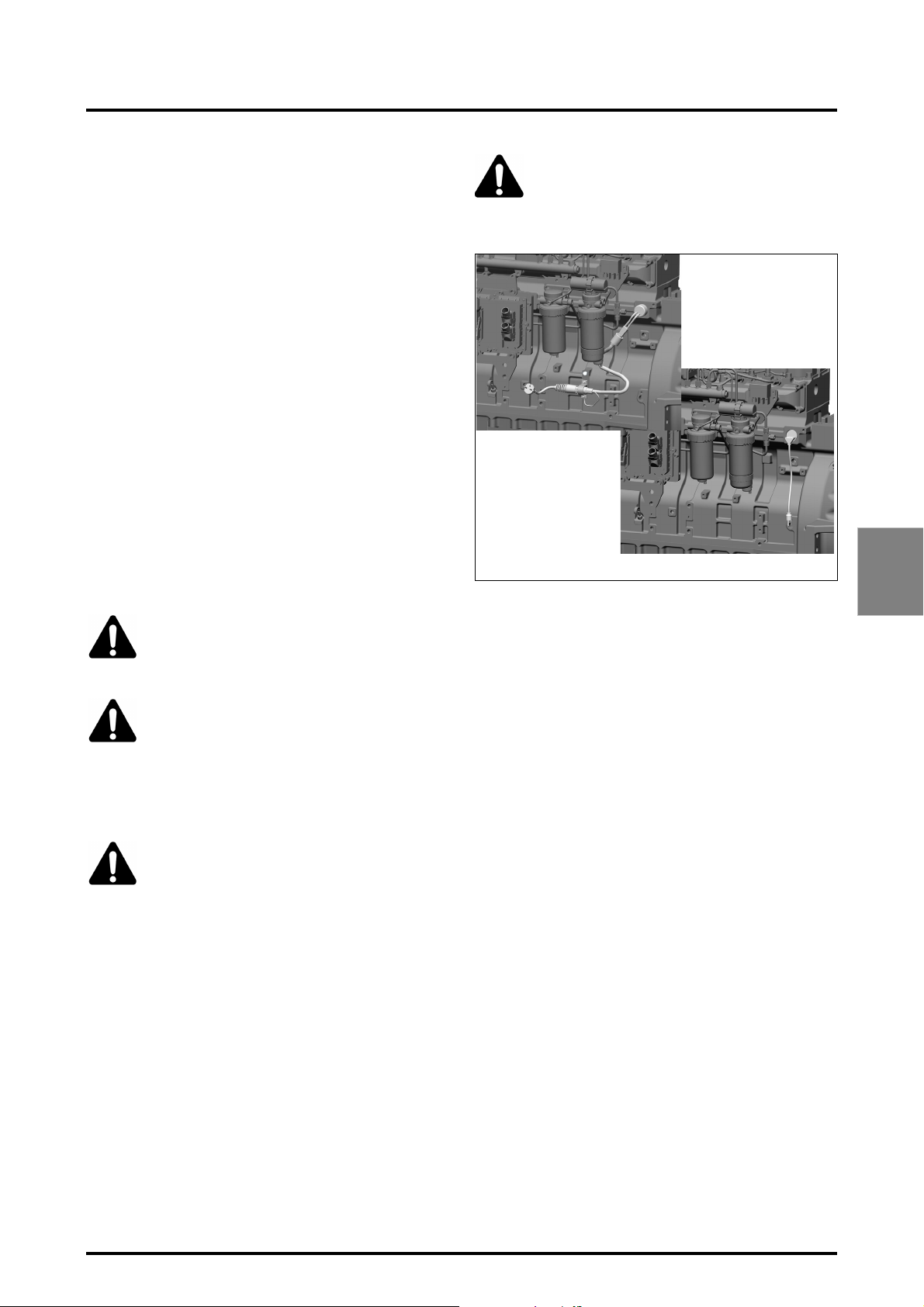
4 . OPERATION
4.1 - RUNNING IN
4.1.1 - The following precautions should be taken
during the running in period
1. Experience has shown that the first 50 hours of tractor
operation have a significant effect on the performance
and life of the engine.
2. From the first operation, the tractor must run at almost
full load of the engine. The engine should always be
allowed to reach a temperature of 60°C (140°F) before
being subjected to full load.
3. It is quite normal for oil consumption to be higher during the running in period. During running in therefore,
check the engine oil level twice a day during the first
50 hours of operation to avoid the risk of lubrication
failure.
4. During running in, frequently check the tightness of all
nuts, bolts and screws. The wheel nuts must be
retightened daily until their torque has stabilised (see
chapter 6).
4.2 - START-UP
IMPORTANT: Before starting the tractor, refer to the
Service Guide, chapter 5.
Z4A-1666-12-05
WARNING: DO NOT plug in heating element
for testing unless immersed in coolant. It is
dangerous to switch on a heating element in
the open air, as the heat released can cause
injury and the element can explode.
Z4A-1667-12-05
Fig. 1
4
DANGER: Before starting, never run the
engine in a closed space. Never run the engine
unless you are sat at the steering wheel of the
tractor.
CAUTION: After a long standstill, to ensure
lubrication of the turbocharger bearings run
the engine on the starter for about ten seconds.
4.2.1 - Starting the engine
Follow the start-up procedure as shown in Fig. 2.
DANGER: Make sure that the PowerShuttle
lever is in neutral position, the handbrake is
applied and the "ParkLock" control on the
steering wheel is engaged.
1. When the ignition key is on, the TC and DC symbols
flash on the right-hand screen of the instrument panel
(Fig. 2).
NOTE: The numbers under T.C. and D.C., required for
the service engineer, correspond to the installed software version.
2. All indicator lights on the instrument panel should
come on. If one of the indicator lights does not come
on, consult your dealer.
4.2.2 - Cold weather starting
A 1000 W heater and connection cable are fitted to help
cold weather starting. The heater operates with 220 or
110 V (depending on option) and in general heats the engine coolant in two hours. Overnight operation may be required when temperatures are extremely low.
8400 EAME
4.5
Page 60
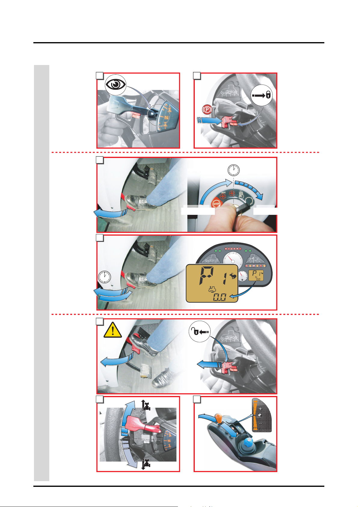
4 . OPERATION
2
>
>
>
>
MAKE SURE
the lever is in ion
NEUTRAL
position.
BEFORE STARTING
>
Declutch and
move the switch
to preheating
position (wait for
2 seconds) then
move it to start
position
>
WAIT FOR 2 S
Before releasing
the clutch pedal
3
4
2s.
21
>
WAIT FOR 2 seconds
2s.
Preheating Start-up
1
5
0
S
1
..
.
.
v
AUTO
AUTO
S
2
.
.
v
.
.
10
RPM x 100
2
15
20
25
>
MAKE SURE the
brake control
(ParkLock) is
ENGAGED
>
>
CHECK
the instrument
panel display
KPH
TO START THE ENGINE
>
6
Press down both
brake pedals and
release the
"ParkLock" brake
contro
>
Engage the lever
in the required
direction of
travel:
DRIVING
KPH
>
87
>
Operate the
control to + or to increase or
decrease speed
4.6
Fig. 2
8400 EAME
Page 61
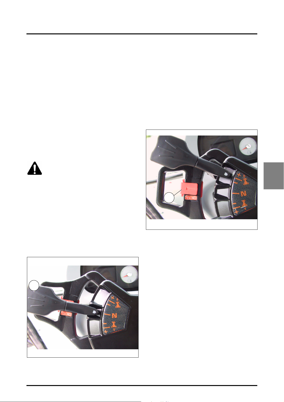
4 . OPERATION
4.3 - STOPPING THE ENGINE
Reduce the engine speed to idling for a few seconds, then
turn the ignition key to the "Stop" position.
IMPORTANT: Do not stop the turbocharger engine suddenly when the engine is running at high speeds,
because the turbine will continue turning on its own but
will no longer be lubricated. Slow the engine before
stopping it.
Move the PTO knob to neutral position before starting
the engine.
4.4 - DRIVING THE TRACTOR
4.4.1 - Foot throttle
The use of the foot throttle makes it possible to exceed the
engine speed set by the hand throttle. When the foot throttle pedal is released, the engine speed returns to that set
by the hand throttle.
CAUTION: When using the foot throttle, the
hand throttle should be placed in the "idle"
position.
Do not keep your foot on the clutch pedal, or maintain
it at mid-travel.
Always descend slopes with the tractor in gear and the
clutch engaged.
When turning on headlands with heavy, mounted
implements, reduce engine speeds during the
manoeuvre. If the engine is not running steering is not
power assisted.
4.4.2 - PowerShuttle control
Control located to the left of the steering wheel (1. Fig. 3)
The PowerShuttle control is used to quickly change direc-
tion of travel (forward or reverse), and to change the speed.
will be displayed on the instrument panel right-hand
screen.
When the tractor is travelling, each change to the direction is with the control (1) without declutching.
NOTE: It is recommended to use the clutch pedal for all
precise manoeuvring (attachment of implements, etc.).
4.4.3 - "ParkLock" electromechanical operated brake (optional)
A Fig. 4: A control located to the left of the steering wheel
allows the operator in the driver’s seat to control the "activated" and "deactivated" ParkLock" electromechanical
brake positions.
Activating the "ParLock":
- the PowerShuttle lever must be in neutral position,
- the control (A) pushed towards the steering wheel
(closed padlock symbol).
The "ParkLock" is engaged.
NOTE: The electronic control ensures that the "Park-
Lock" is engaged as soon as the ground speed drops
below 1 kph. The indicator light on the instrument
panel comes on and the "P" symbol appears on the dig-
ital display.
Deactivating the "ParkLock":
Z2-138
- The control (A) must be pulled outwards (open padlock
symbol).
IMPORTANT: For the "ParkLock" to disengage after
engine start-up, the electronic control must record a
switch of the control (A) from the closed padlock position to the open padlock position. If this condition is not
met, the "ParkLock" remains engaged, even if the control is in the open padlock position.
A
Fig. 4
4
1
Z2-078
Use:
• PowerShuttle: Move the PowerShuttle control in the
required direction of travel, and the corresponding icon
8400 EAME
Fig. 3
DANGER: Engage the control into locked position
(closed padlock symbol) before leaving the driver’s
seat with the engine running.
4.4.4 - Selecting the correct gear ratio
Fig. 6. Select the gear ratio that ensures the best fuel consumption without overloading the engine or the transmission; also remind that the soil conditions in a field may vary
over a few metres. Select a ratio which allows the engine
to operate comfortably at about 75% of its maximum power.
4.7
Page 62
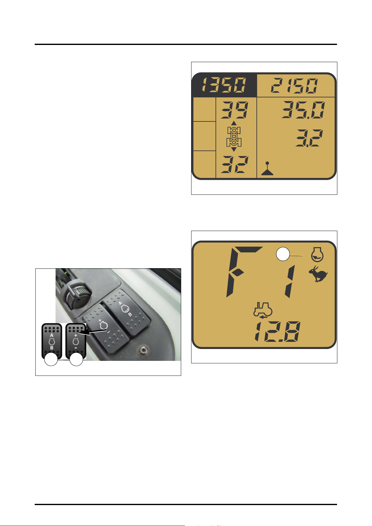
4 . OPERATION
4.4.5 - Preselecting A / B memorised engine speeds
Fig. 5 - This function allows the operator to continuously
choose between two engine speeds stabilised according
to the adjustments selected.
Memorising engine speeds
1. Select the required speed using the foot or hand throt-
tle:
Keep the memory button (A or B (22) pressed down
for 1 to 2 seconds. The speed is memorised and acti-
vated. The operation is the same for both memories (A
and B), and the speed remains memorised even if the
ignition is switched off.
2. No speed must be selected:
Keep the memory button (A or B) pressed down, do
not release it, and the speed increases gradually;
release the button when the selected speed is
reached and the speed is memorised and activated.
Press button A / B to select or deselect the engine speed
predefined by button (23).
Each time button (23) is pressed, engine speed is increased/decreased by 10 rpm. A continuously applied pressure allows to rapidly increase or decrease the engine
speed to be memorised.
S
1
v
S
v
2
.
.
Z3A-1287-11-04
- The engine symbol appears on the digital display, along
with the letter A or B, indicating the active memorised
engine speed (e.g.: memorised speed A (2 Fig. 7).
Fig. 6
NOTE: When driving at a preselected accelerated
engine speed, press once on the key A/B or on the brake
pedals, or quickly press the throttle pedal (kick down) to
automatically drop to idle speed.
22
Z2-438-05-03
23
Z2-437-05-03
Fig. 5
2
A
MPH
Z3A-1288-11-04
4.4.5.1 - Range shifting
To shift from "Hare" range or from "Tortoise" range (button
on console) engage the required range by keeping the gear
shift switch (
corresponding indicator light will light up on the instrument
panel).
5) pressed until the ratio is fully engaged (the
Fig. 7
4.8
8400 EAME
Page 63
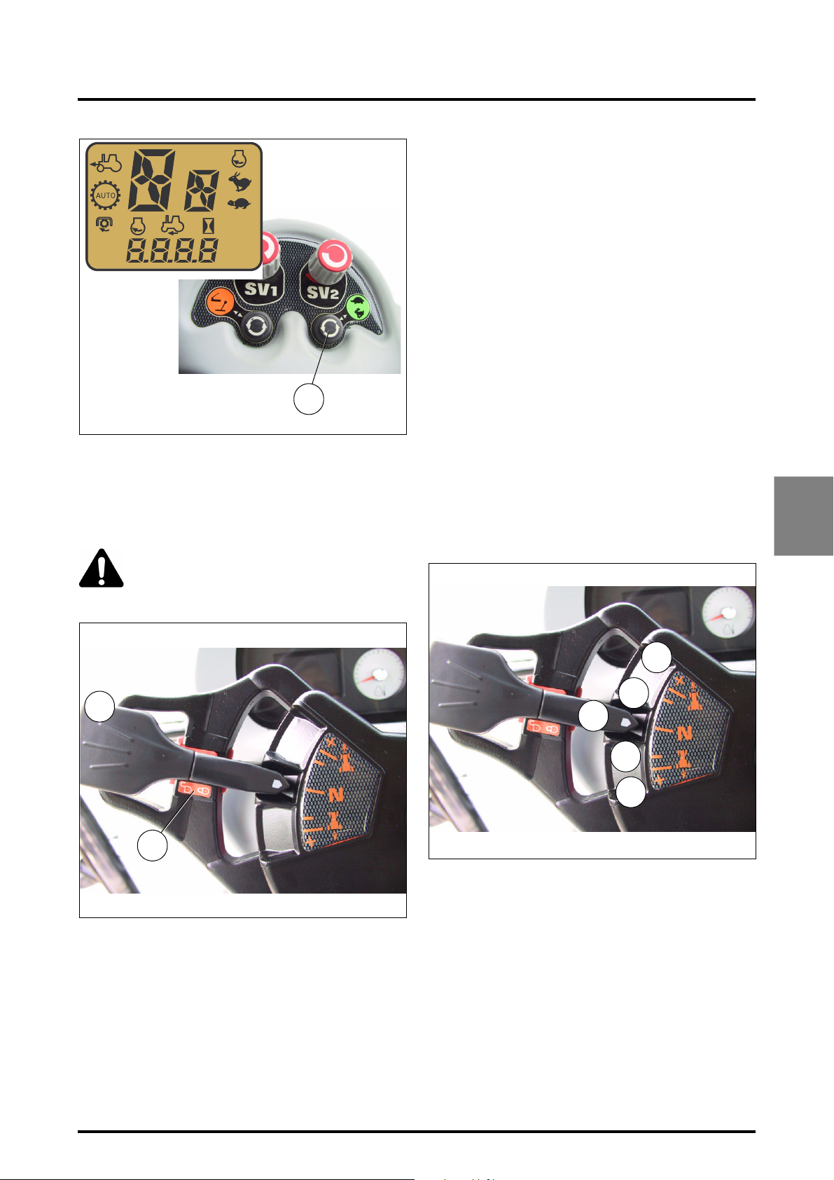
4 . OPERATION
A
540
1000
ECO
Z3B-147-03-05
Z2-440-05-03
A
KPH
MPH
RPM
B
5
Fig. 8
NOTE: Do not rush when carrying out this manœuvre.
The "Hare to Tortoise" synchronised range change is
only possible when the tractor is stationary and the
clutch pedal is pressed down. The “Tortoise to Hare”
change is only possible at speeds above 5 kph.
DANGER: Before leaving the seat it is mandatory to move the PowerShuttle control (1. Fig.
9) to NEUTRAL position and engage the brake
control on steering wheel ref. A ParkLock.
4.5 - DYNA VTTRANSMISSION
4.5.1 - General
Models fitted with Dyna VT transmission have continuous
variable transmission in the forward and reverse positions.
Power is transmitted hydrostatically or mechanically, OR
hydrostatically and mechanically:
• Slow forward travel = Power transmission is hydrostatic
primary / mechanical secondary
• Fast forward position = Power transmission is hydrostatic secondary / mechanical primary.
4.5.2 - Use
There are no mechanical speeds like on a standard tractor.
4.5.2.1 - Selecting direction of travel
Dyna VT transmission operation has a user interface and a
specific display. The PowerShuttle lever (Fig. 10) controls
direction of travel, and speed increase and decrease.
Ratio selection positions:
1. Neutral
2. Forward travel deceleration
3. Forward travel acceleration
4. Reverse travel deceleration
5. Reverse travel acceleration
4
1
A
Z2-078
NOTE: If the tractor is working in conditions where
water comes higher than the wheel hubs, corrosion
damage can occur to some of the components.
Consult your dealer or agent for sealing precautions.
Failure to do so can invalidate the warranty.
Fig. 9
Z2-078
3
2
1
4
5
Fig. 10
8400 EAME
4.9
Page 64
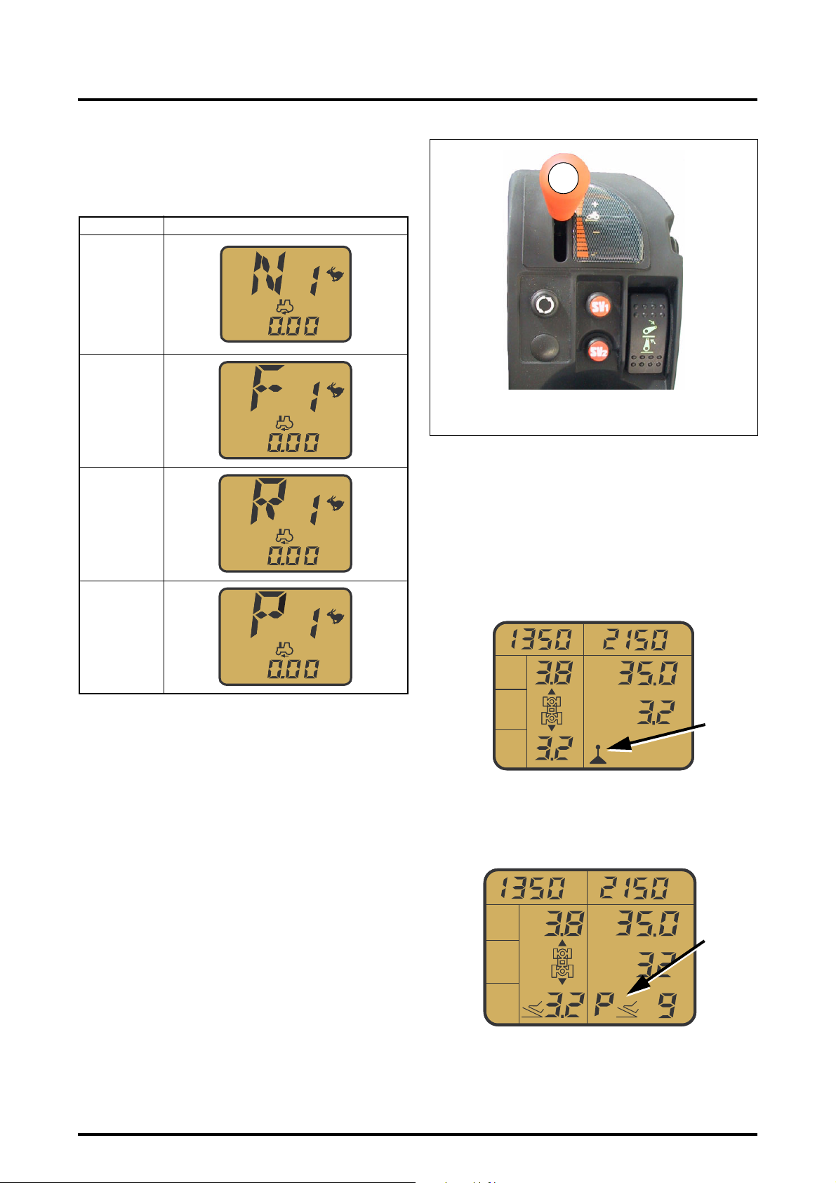
4 . OPERATION
As soon as you move the left-hand lever in the required direction of travel, the corresponding symbol is displayed on
the instrument panel right-hand screen, as shown in the
following table:
Position Corresponding screen
1. Neutral
KPH
Z3A-1299-10-04
2. Forward
KPH
Z3A-1298-10-04
3. Reverse
KPH
Z3A-1297-10-04
4
Z3A-749-07-04
Fig. 11
During tractor movement, if the clutch pedal is activated,
the transmission ratio is decreased until speed is zero.
The armrest lever (4 Fig. 11) also controls speed increases
and decreases depending on the direction of travel.
4.5.3 - Different control modes
NOTE: At start-up, the tractor is in lever mode, transmission control is performed with the lever only.
4. ""ParkLock"
engaged
KPH
Z3A-1460-06-05
When the tractor is operating, the direction is always
changed with the left-hand lever (Fig. 10).
To start the tractor moving (forward or reverse travel), the
correct transmission ratio must be selected.
4.5.2.2 - Fast reversing
When changing the direction of travel, the tractor decreases to a halt, then accelerates in the opposite direction.
Shifting is inhibited but not blocked when the following
functions are active:
• the underspeed supervisor
• the turbo clutch function
4.5.3.1 - Lever mode
S
1
v
S
2
v
Z3A-1277-11-04
The speed depends on the position of the armrest lever (4
Fig. 11).
4.5.3.2 - Pedal mode
S
1
v
S
2
v
.
.
4.10
Z3A-1453-05-05
When the tractor is started, the throttle pedal must be released and button (5 Fig. 12) pressed.
Transmission is controlled exclusively by the pedal. To adjust the ground speed operate the SV2 potentiometer
8400 EAME
Page 65
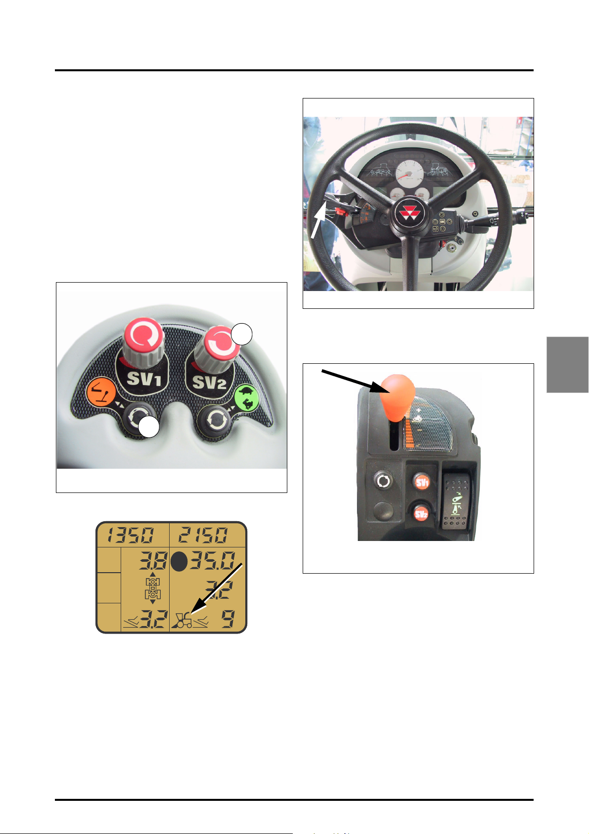
(6 Fig. 12) (max. 16 kph, min. 3 kph); the value is displayed
to the right of the "pedal" icon on the DOT MATRIX screen.
Engine speed is electronically adjusted depending on transmission speed. There are two possible settings in pedal
mode:
• Power mode: (P is displayed)
This is the max. speed at the max. engine speed (no programmed max. engine speed).
• Economy mode: (E is displayed)
In this case, maximum speed at 1800 rpm engine speed
(1800 is the maximum engine speed in this mode).
NOTE: In pedal mode, each time button (5 Fig. 12) is
pressed , the setting changes between power mode
and economy mode. If the lever is pressed for 2 seconds when in pedal mode, the tractor exits pedal mode.
4 . OPERATION
5
Z2-440-05-03
4.5.3.3 - Self-propelled mode
S
v
1
6
Fig. 12
Z3A-709-07-04
The progressivitity of Dyna VT (Fig. 14) armrest lever
makes transmission ratio adjustment easier. When decreasing the ratio, the tractor stops at 0 kph (dynamic stop).
Z3A-749-07-04
Fig. 13
Fig. 14
4
S
2
v
Z3A-1454-05-05
Access to self-propelled mode is possible only if engine
speed A or B is selected. In this mode, the user sets the
engine speed with memories A and B, and ground speed is
controlled by the throttle pedal and hand throttle.
4.5.4 - Setting ground speed
To increase or decrease speed, both levers can be used.
The left-hand lever (Fig. 13) adjusts the speed by incre-
ments of 0.1 to 2 kph, depending on the length of time the
lever is activated.
8400 EAME
.
The right-hand lever travels at varying increments depending on its position. It has 3 increment types (Fig. 15):
• Increments of 0.03 to 0.5 kph in slots 1 and 4.
• Increments of 1 kph slots 2 and 5.
• Increments of 2 kph in slots 3 and 6.
A mechanical stop is felt when shifting from slots 1 to 2
and 2 to 3 and from slots 4 to 5 and 5 to 6.
NOTE: If speed regulation is active, pressing the lever
automatically deactivates it.
4.11
Page 66
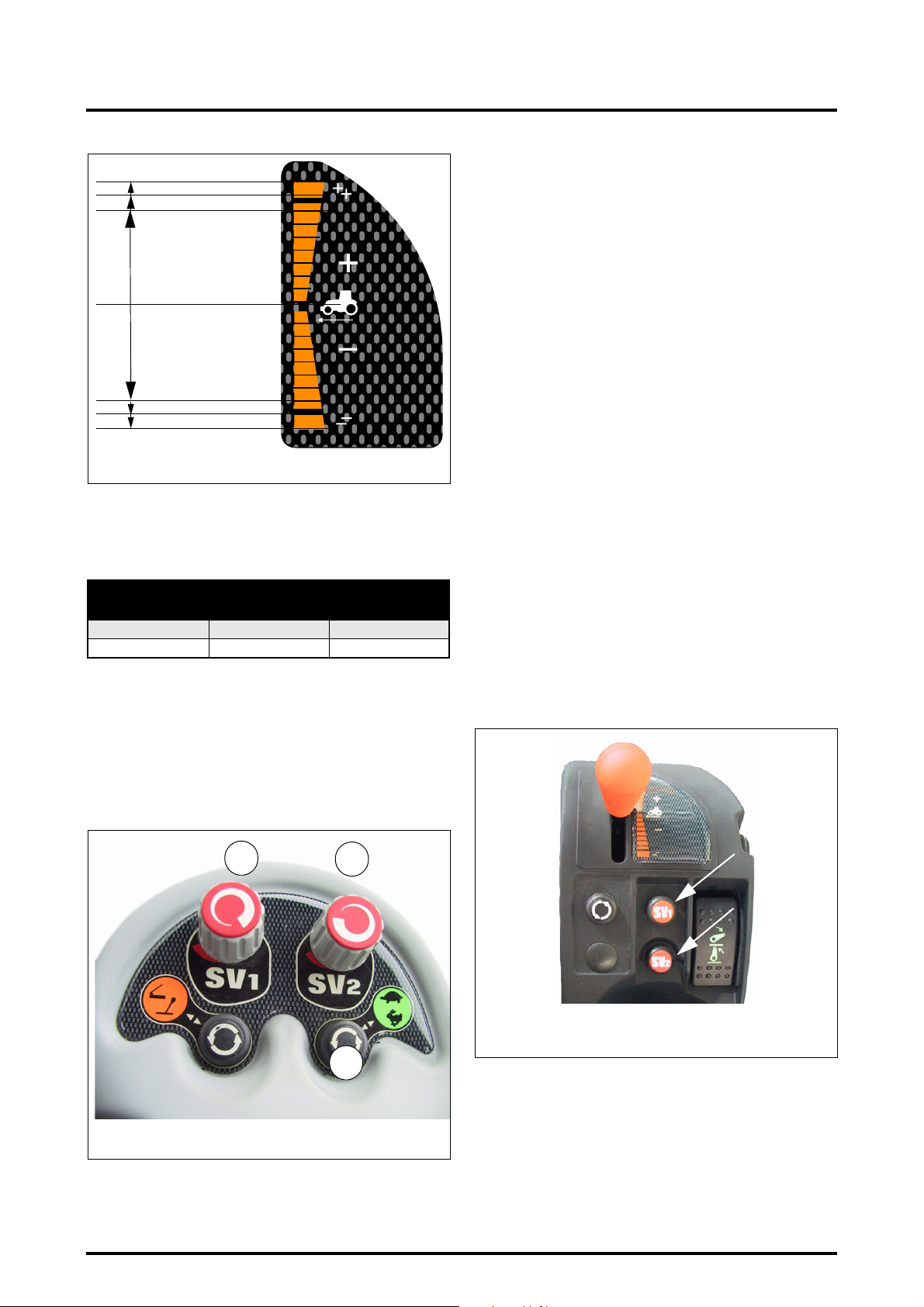
4 . OPERATION
SLOT 3
SLOT 2
SLOT 1
SLOT 4
SLOT 5
SLOT 6
Z3A-1455-05-05
4.5.5 - Selecting Hare or Tortoise range
The Dyna VT transmission possesses 2 gear ranges. Each
range is limited, as shown by the following table:
Gear range (in kph)
tortoise Hare
Forward
Reverse
0.03 to 28 0.03 to 50
0.03 to 16 0.03 to 38
Button 1 on the right-hand console (Fig. 16) allows to shift
from Hare to Tortoise range. Shifting is possible while the
tractor is moving, but only from Tortoise to Hare range.
When shifting from Hare to Tortoise, the PowerShuttle lever (Fig. 13) must be in neutral position, or the clutch pedal
must be pressed down.
The range is displayed on the instrument panel right-hand
screen.
Z3A-1455-05-05
Fig. 15
4.5.6 - SV1 and SV2 Speed regulators
The ground speed is held constant.
The speed regulator function allows the user to easily store
and recall a ground speed.
Two separate memory buttons (SV1 and SV2) are available
(Fig. 17). This allows to store two ground speeds, e.g.
working speed and transport speed).
The memorised speeds are displayed to the right of the
DOT MATRIX screen (1 and 2 Fig. 18). When the speed
regulator is used, the corresponding memory is highlighted
on the screen. In Fig. 18, stored speed SV1 is activated.
4.5.6.1 - Presetting SV1 and SV2 speeds
The ground speed value can be adjusted using SV1 and
SV2 potentiometers (2 and 3 Fig. 16). The adjusted values
are automatically stored and remain in memory even after
the tractor engine is stopped.
NOTE: It is also possible to change the stored speed
when the tractor is driving with an activated “regulated” speed.
To shift between stored speeds, press once on the SV1 or
SV2 button (Fig. 17). Press for more than 3 seconds on button SV1 or SV2 (Fig. 17) to store the actual tractor speed
and replace the previous stored speed.
The speed regulator can only be activated if the following conditions are met:
• Clutch pedal not activated
• The tractor is running and has reached restart speed
• The engine speed is higher than 1100 rpm
Z2-440-05-03
4.12
2
3
Z3A-749-07-04
Fig. 17
1
Fig. 16
8400 EAME
Page 67
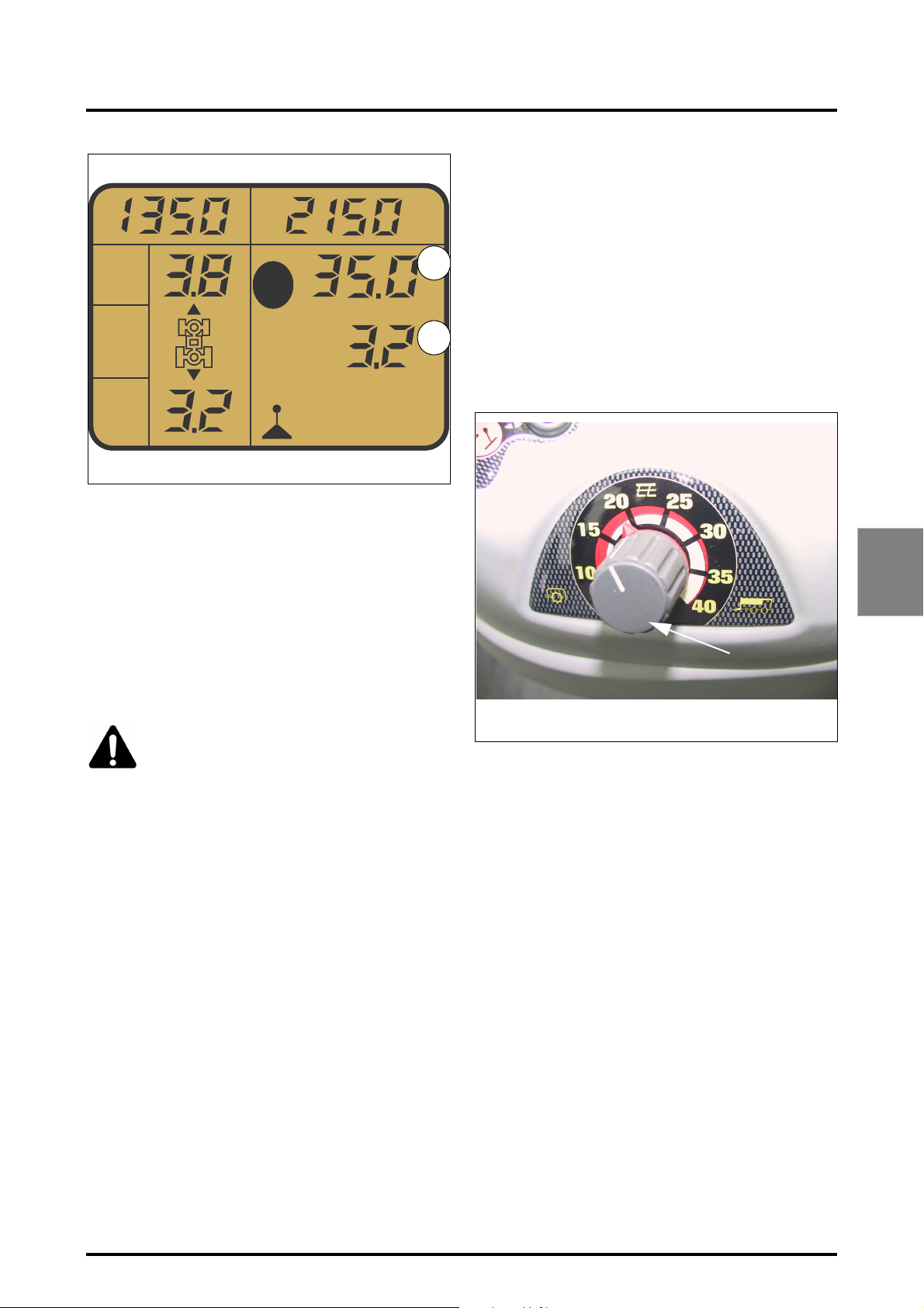
S
S
v
v
S
v
1
1
2
4 . OPERATION
4.5.7 - Engine underspeed supervisor
The underspeed supervisor is automatically activated
when the engine speed drops in case of stress. The tractor
speed is then decreased automatically by the gearbox control to prevent the engine speed from dropping further.
Supervisor operation
1
The underspeed supervisor is automatically activated
when the engine speed drops below 180 rpm under load.
The supervisor value is set by a potentiometer located on
the right-hand console (Fig. 19). Changes take effect imme-
2
diately. It is therefore possible, during use, to set tractor
.
operation to the corresponding values. When the engine
underspeed supervisor is activated, an icon is displayed on
the left-hand screen (Fig. 20).
Z3A-1457-06-05
Fig. 18
If these conditions are not met the “speed regulator” function is deactivated and the instantaneous transmission ratio
is maintained, with no subsequent control. Start-up with
the "speed regulator" function is not possible. Stored
speeds can be activated in both directions of movement.
The “speed regulator” mode is deactivated when:
• The drive lever is used
• The brake pedal or engine brake is activated
• Engine speed drops below 1100 rpm
• The neutral switch is activated
• The range is changed (Hare or Tortoise).
CAUTION: Any use of the brakes automatically deactivates the speed regulator (SV1 or
SV2) as well as the stored engine speed (A or
B).
4
Z2-452-05-03
Fig. 19
Potentiometer set to 10:
The ground speed decreases to maintain a constant engine
speed.
Potentiometer set to 40:
The engine speed increases to maintain a constant ground
speed.
Potentiometer set between 10 and 40:
Combination of the two previous explanations.
8400 EAME
4.13
Page 68
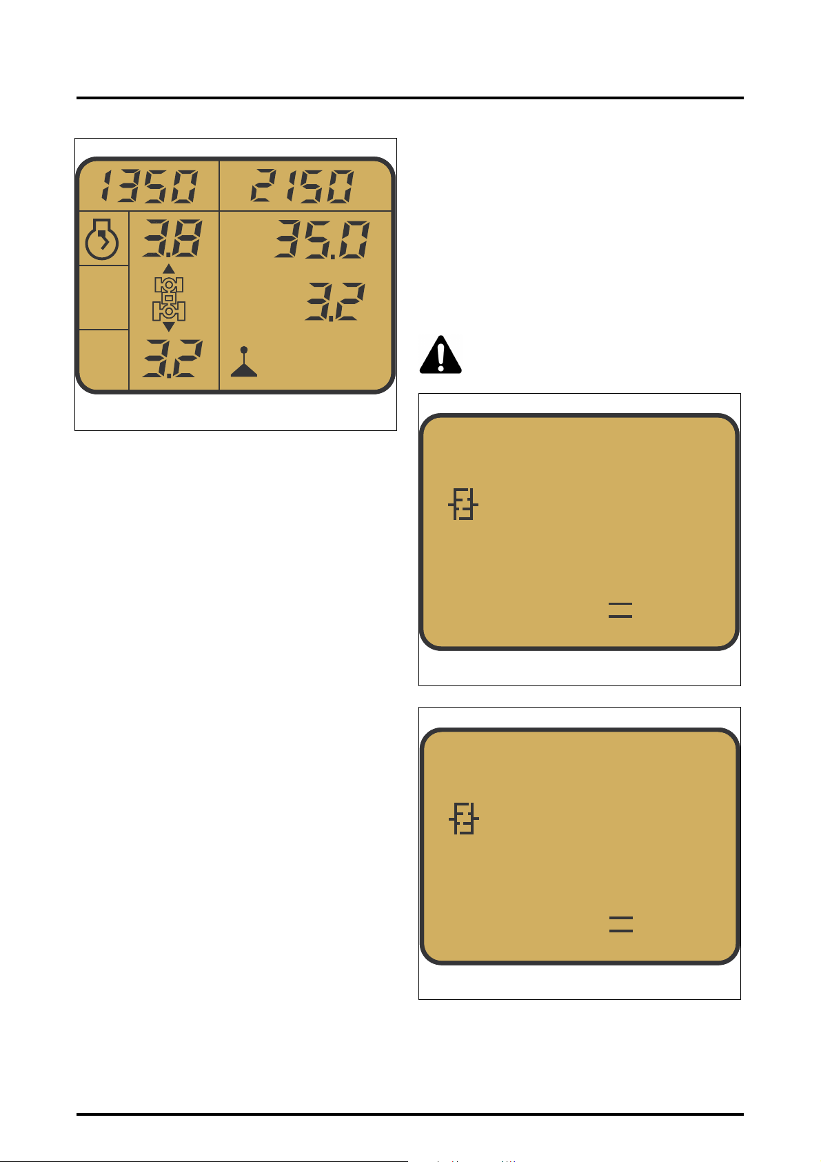
4 . OPERATION
Z3A-1294-11-04
S
v
S
v
1
2
4.5.8.3 - Coupler function under traction
The coupler function is activated when the engine speed
drops below 1400 rpm, as the pressure in the hydrostatic
loop decreases in proportion to the drop in engine speed.
Just like a coupler, the function limits engine overload and
avoids stalling.
The coupler can be validated or not from the DOT MATRIX.
NOTE: To activate (Fig. 21) or deactivate (Fig. 22) the
coupler function, move the PowerShuttle lever to neutral, fully press down the clutch pedal and press the OK
.
Fig. 20
button for 5 seconds.
WARNING: The coupler function is "ON" by
default at start-up whatever is the status
when the engine stops.
4.5.8 - Clutch-coupler function
4.5.8.1 - Clutch function
Although the Dyna VT transmission has neither forward
clutch nor coupler, the tractor possesses a clutch pedal.
This pedal allows to control the traction effort (as with
standard clutch slip). When an obstacle appears suddenly,
the tractor can be rapidly stopped, just like a conventional
tractor, by pressing the clutch and brake pedals.
4.5.8.2 - Coupler function
Traction power is limited at low engine speed thanks to a
pressure relief valve located on the transmission hydrostatic loop.
In connection with engine speed, the coupler function is
achieved by modulating the pressure in the hydrostatic circuit. Thus, the coupler function replaces the measured action of a clutch pedal.
CLUTCH
ON
0k 5s off
Z3A-1295-11-04
Fig. 21
CLUTCH
OFF
4.14
0k 5s off
Z4A-1670-12-05
Fig. 22
8400 EAME
Page 69
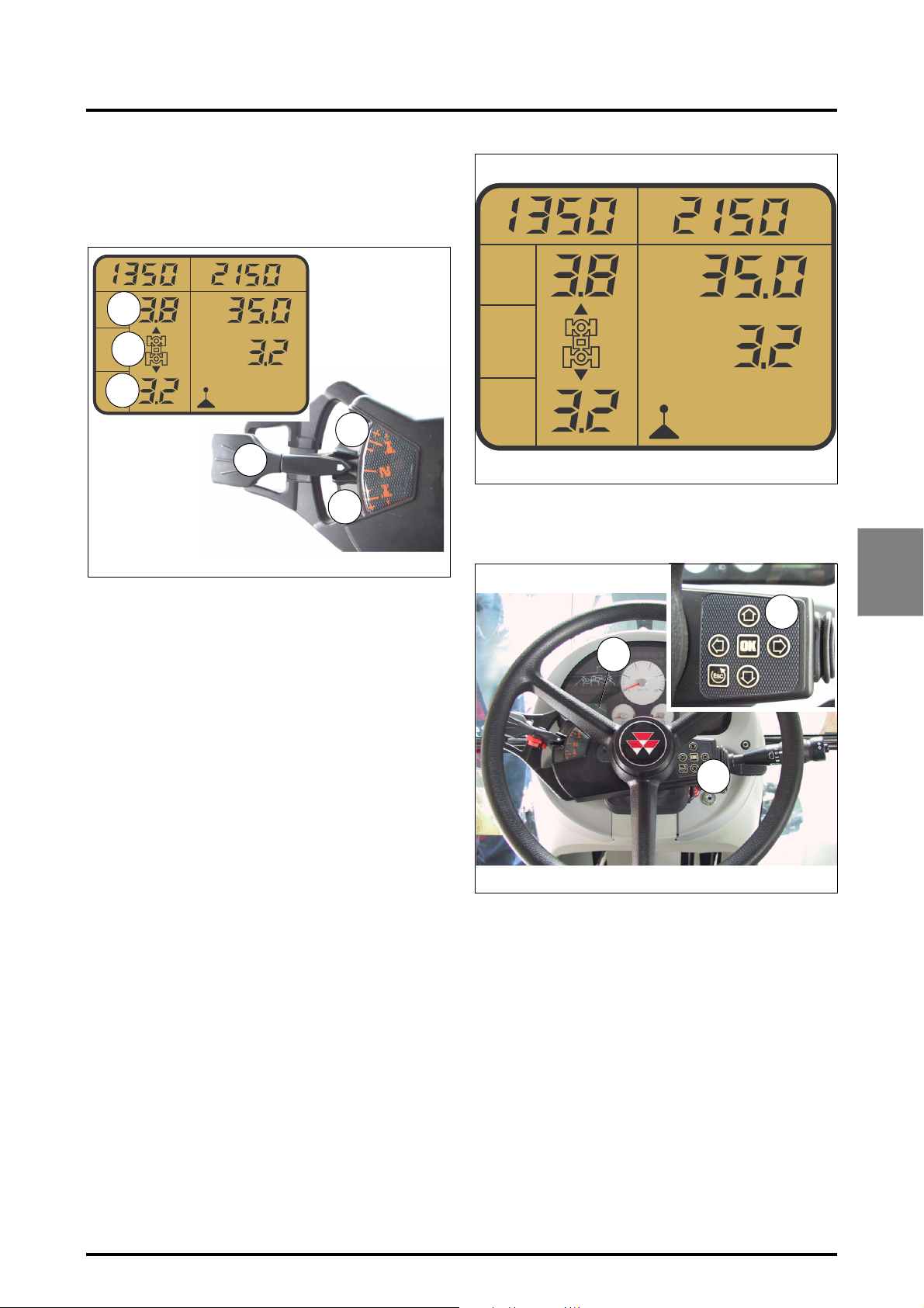
4.5.9 - Setting restart speeds for shifting
To activate the preset values, press the clutch pedal, the
tractor icon (2 Fig. 23) flashes. The required value can be
set usint the PowerShuttle.
1
2
3
S
S
1
v
2
v
.
4 . OPERATION
S
1
v
S
v
2
.
Z3A-1277-11-04
4
Z2-441-05-03
To set forward value (1 Fig. 23):
Depress the clutch pedal, put the PowerShuttle lever in po-
sition 5, then move the PowerShuttle lever to + or – to adjust to the required value.
To set reverse value (3 Fig. 23):
Depress the clutch pedal, put the PowerShuttle lever in position 6, then move the PowerShuttle lever to + or – to ad-
just to the required value.
Presettings are different in the Hare and Tortoise ranges.
They are stored when the engine is turned off. The displayed value corresponds to the speed in kph obtained
when the engine speed is 1800 rpm. If the preset values
are set to 0.2, reversal will occur at the same forward and
reverse speeds.
NOTE: In all cases, the dynamic stop can be activated
by moving the left-hand "forward to neutral" or
"reverse to neutral" lever.
5
6
Fig. 23
Z3A-1277-11-04
Ref. 4: DOT MATRIX screen (Fig. 25)
Ref. 5: DOT MATRIX controls
Z3A-1202-10-04
4
Z3A-709-07-04
Fig. 24
4
5
5
Fig. 25
4.5.10 - Using the DOT MATRIX screen
The DOT MATRIX screen is initialised when starting the
tractor (4 Fig. 25). To access the different menus, press the
DOT MATRIX control buttons (ref. 5) and follow the instructions given in the table on the next page.
8400 EAME
4.15
Page 70
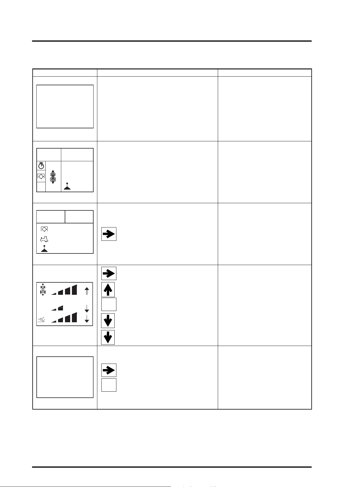
4 . OPERATION
Z
Z
Screens Access Function
HYDR OIL
95 %
Z3A-992-08-04
1055 800
S
1
v
S
v
2
35.0
3.2
3.2
AUTO
0.2
3A-1306-11-04
Ignition before engine start
(ignition key on +ACC position)
Starting the tractor
Displays the filling level of the auxiliary oil tank
Auxiliary oil level screen
(0-100%):
- 100%: tank full.
- 50%: warning threshold.
When the auxiliary oil tank level drops to
< 50%, it is automatically displayed every
4 minutes (press ESC to return to the main
screen).
If sensor problem, ERROR is displayed instead
of the filling level.
Start-up screen
Displays the restart speeds, the SV1 and SV2
speeds, engine supervisor, PTO, pedal mode,
eco mode or lever mode.
1430 1160
0
RPM
0 %
S
1
2,6
v
Z3A-985-08-04
Delay
No
Sv
-
3A-1307-11-04
DISTANCE
km
0 0 6 3. 9 0 0
0k 5s = › 0
OK
OK
To display from the start-up screen
To display from the previous screen
To increase or decrease reverse shuttle sensitiv-
ity (all modes).
Delay: Allows a 1.5 seconds delay to be authorised or not when reversing direction of travel
Sv: Display progressivity response time (select
speed Sv1 or Sv2 and press the arrow)
Pedal mode deceleration progressivity adjustment.
To display from the previous screen
To reset distance to zero.
Displays memorised engine speeds, PTO
Work screen
speed, actual wheel slip rate,lever mode, pedal
mode (power or eco), self-propelled mode and
SV1 and SV2 speeds.
Reverse shuttle sensitivity
Allows direction reversal response time to be
set.
The delay starts once the PowerShuttle lever is
activated If the delay is authorised, declutching
takes place 1.5 seconds after the lever is activated. If not authorised, declutching takes place
as soon as the lever is activated.
Distance screen
Displays the total distance run
Z3A-1456-05-05
4.16
8400 EAME
Page 71
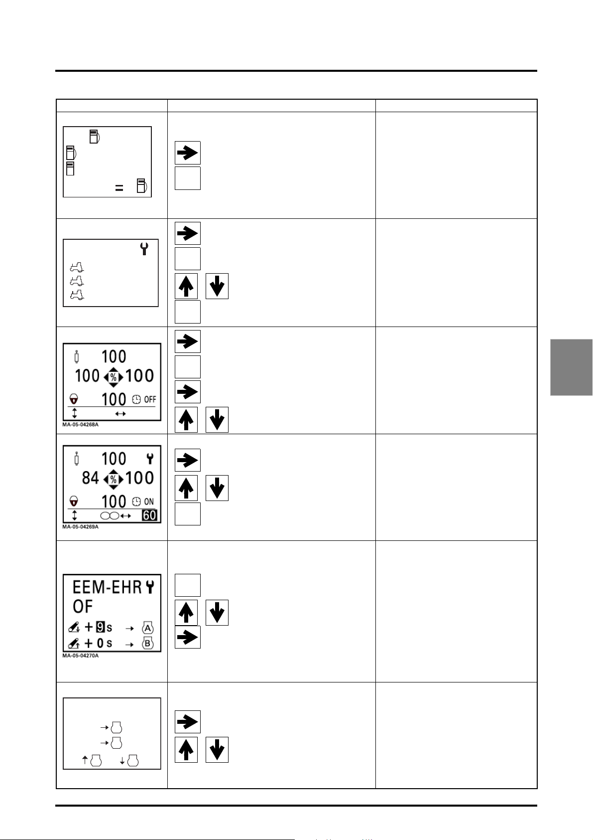
Screens Access Function
T
( 1 )
0
T
500
ok 5s 0
Z3A-996-08-04
10
4 . OPERATION
To display from the previous screen
Indicates fuel used:
OK
Press 5 seconds to reset
0
To display from the previous screen
0: Quantity of fuel used since last reset.
T: total fuel used. This value is not interchangeable and cannot be set to zero.
Fuel used screen
Z3A-997-08-04
SLIP
Off
Max0%22%
OK
ESC
OK
ESC
Press to enter the settings menu. The symbol
appears.
To set the required wheel slip percentage value
Allows to exit the settings screen
To display from the previous screen
Press to enter the menus
To select one of the displayed flow rate values
or timing
To modify displayed flow rate values
When timing is selected, it is possible to display
the type of timing (value or infinite)
To adjust the timing value
Allows to exit the settings screen and
validate settings
Wheel slip screen (optional)
Allows to adjust maximum allowable wheel slip
and display current wheel slip.
Joystick setting menu (1/2) (if
Datatronic 3 is not installed)
This menu allows to adjust the flow rate values
of each spool valve controlled by the Joystick. If
the Joystick is locked (padlock displayed on
screen) press the blue armrest ON/OFF button
near the PTO control.
Joystick setting menu (2/2) (if
Datatronic 3 is not installed)
This menu allows to activate or deactivate timing, and can be adjusted from 0 to 60 seconds
or to infinite mode.
4
EEM-SV
SV1
SV2
A B
Z3A-986-08-04
8400 EAME
Headland 2 screen (if Datatronic 3 is
This menu allows to adjust the engine speed
OK
A
ON
B
ON
Allows to activate the mode or validate the values
Used to shift from one line to another
Allows to set the seconds value of the
displayed time
To display from the previous screen
To activate or deactivate one of the two
functions
when changing linkage status (work or transport). The operating conditions are:
- ON mode,
- PowerShuttle lever out of neutral,
- tractor moving,
- When the linkage transport mode is
selected, engine speed B is activated after
the preset time.
- When the linkage working mode is selected,
engine speed A is activated after the preset
time.
This menu is used to vary the engine speed
during activation of SV1 and SV2 memorised
ground speeds.
not installed)
Headland 1 screen
4.17
Page 72
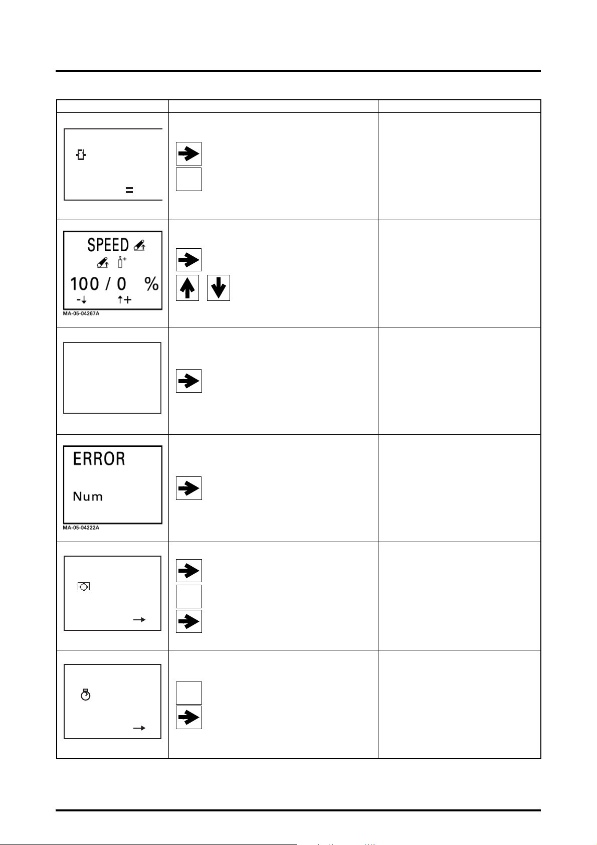
4 . OPERATION
Screens Access Function
CLUTCH
ON
0 k 5 s off
Z3A-998-08-04
Electro Valves
V1 -
3
99
100
100
100
100
V1 +
V2 +
V3 +
V4 +
V5 +
V6 +
V2 V3 V4 V5 V6 -
100
99
100
100
100
100
OK
To display from the previous screen
Press 5 seconds to switch from On to OFF
To display from the previous screen
To modify displayed linkage and spool
valve flow rate values
To display from the previous screen
Displays whether the clutch coupler function is
Clutch coupler screen
on or off.
Linkage and EHS valves menu
This menu allows to give priority to the auxiliary
spool valves over the linkage, and vice versa.
Maximum linkage value: 100
Minimum spool valve value: 0
Minimum linkage value: 20
Maximum spool valve value: 80
Valves display screen (option if
Datatronic 3 is not installed)
Allows flow rate of each valve to be displayed
FREQ OUT
40
Hz/r/s
ok = OUT
MA-11-06144A
FREQ OUT
40
Hz/r/s
ok = OUT
MA-11-06145A
OK
OK
To display from the previous screen
To display from the previous screen
Used to change the reference speed (next
screen).
To exit the FREQ OUT menu
Used to change the reference speed (next
screen).
To exit the FREQ OUT menu
Displays all of the tractor error codes. Each
Error code screen
error code is displayed for 4 seconds in a loop.
PTO speed output adjustment screen
(models fitted with electronic injection)
Used to adjust the PTO speed reference frequency (40 to 60), (consult your dealer for
details of connection and value adjustments)
Engine speed output adjustment
screen (models fitted with electronic
injection)
Used to adjust the engine speed reference frequency (40 to 60), (consult your dealer for
details of connection and value adjustments).
4.18
8400 EAME
Page 73
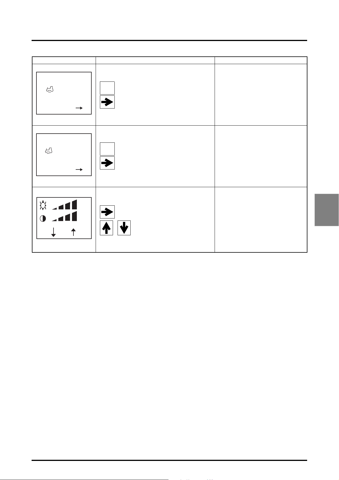
4 . OPERATION
Screens Access Function
FREQ OUT
Hz/m/s
ok = OUT
MA-11-06146A
FREQ OUT
R
Hz/m/s
ok = OUT
MA-11-06147A
-
Z3A-1450-05-05
130
130
+
OK
OK
Used to modify the reference speed (next
screen).
To exit the Frequency menu
Used to return to the PTO FREQ OUT screen.
To exit the Frequency menu
To display from the previous screen
To increase or decrease the value
Ground speed output adjustment
screen (models fitted with electronic
injection)
Used to adjust the current speed reference frequency (36 to 144), (consult your dealer for
details of connection and value adjustments).
Current speed output adjustment
screen (models fitted with electronic
injection)
Used to adjust the current speed reference frequency (36 to 144), (consult your dealer for
details of connection and value adjustments).
4
Brightness/contrast screen
Allows to set screen brightness and contrast
IMPORTANT: When stopping the engine, all DOT MATRIX functions except the coupler function (CLUTCH) shift to
OFF position.
8400 EAME
4.19
Page 74
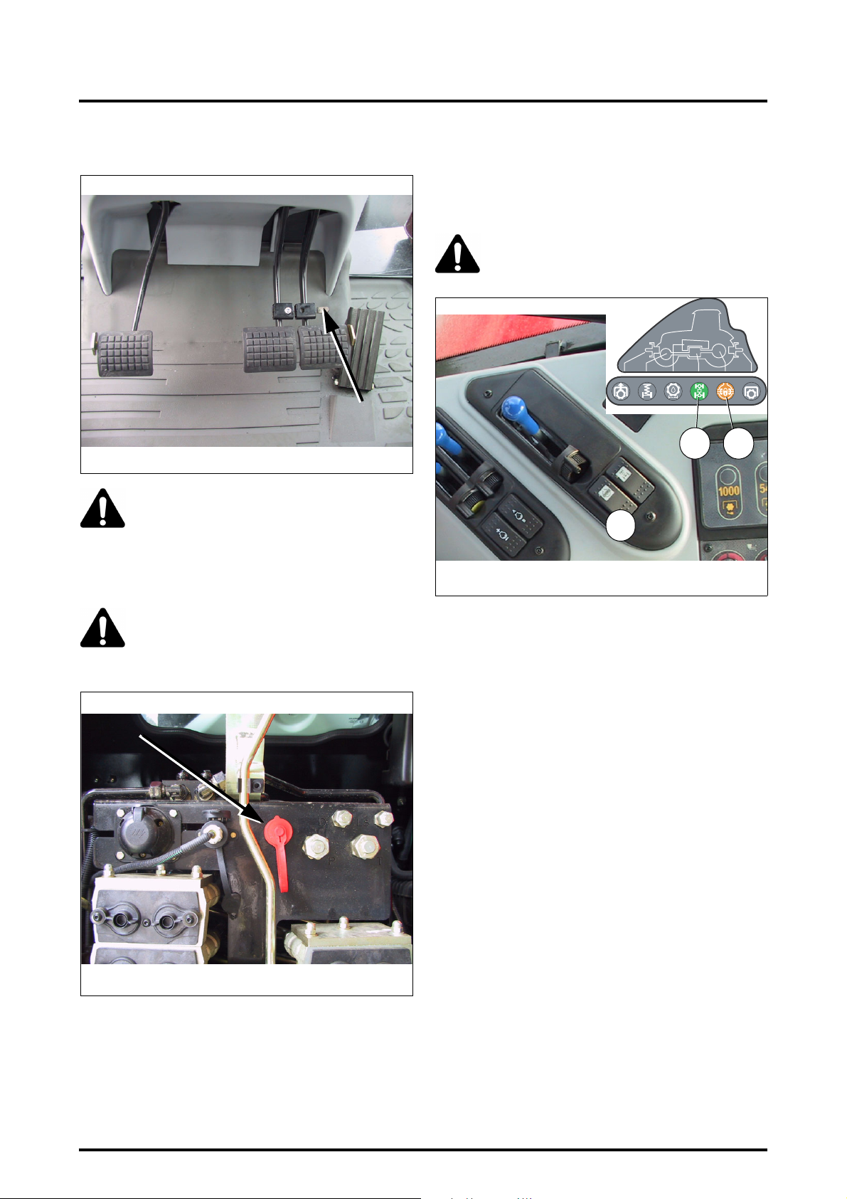
4 . OPERATION
4.6 - BRAKES
Z2-410-05-03-A
DANGER: When driving at speed or on the
road, the two brake pedals must be locked
together (Fig. 26). Only the foot throttle
should be used, and the throttle lever must be
in neutral position.
Check that A/B memorised speed is not activated.
Fig. 26
4.7 - DIFFERENTIAL LOCK
The differential lock is used to prevent the rear wheels
from slipping in relation to one another and thus limits tractor wheel slip during field work.
CAUTION: During manoeuvres, turning is difficult with the differentials locked.
Z3A-1305-11-04
54
12
Z3A-1042-09-04
Fig. 28
Z3A-751-07-04
WARNING: Trailer brakes (Fig. 27). To activate
the trailer brakes, connect the trailer hose to
the union at the back of the tractor and lock
the brake pedals together.
Fig. 27
To engage the differential lock, press the switch (12Fig.
28). Differential lock engagement simultaneously engages
the front axle, the differential lock (5) and front axle (4) instrument panel indicator lights come on.
To disengage the differential lock, press the switch again
(1).
IMPORTANT: DO NOT engage the differential lock
when a wheel is slipping.
Disengaging the differential lock does not disengage
the front axle.
• Automatic engagement and disengagement of the differential lock:
This function is permanent and either activated or deactivated as soon as the linkage control is activated (e.g.: Operation at headlands). As soon as the linkage switch is
pressed in Lift position, the differential lock disengages,
then, when the linkage switch is pressed in Down position,
the differential lock automatically engages.
IMPORTANT: Any use of the brakes cancels the differential lock. Press the switch (12 Fig. 28) again to reengage it.
DO NOT engage the differential lock when a wheel is
slipping.
4.20
NOTE: For optimum performance, engage the differential lock when starting a run.
8400 EAME
Page 75
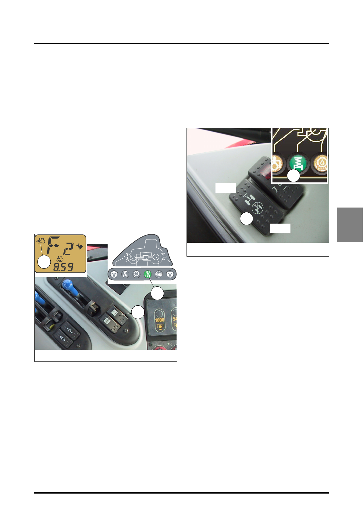
4 . OPERATION
4.8 - FOUR WHEEL DRIVE
When 4WD is engaged, the front wheels are driven. This
function is strongly advised for field work to keep wheel
slip to a minimum.
IMPORTANT: To avoid damaging the front axle, it must
be disengaged for road use.
There are two modes of 4WD operation:
1. Automatic mode:
At tractor start-up, the front axle is in automatic mode. To
engage the front axle, press the switch (11 Fig. 29). The
corresponding instrument panel indicator light comes on (4
Fig. 29) and the 4WD automatic mode symbol appears on
the digital display (A Fig. 29).
When this mode is activated, the front axle is automatically
disengaged at speeds exceeding 14 kph and is automatically re-engaged as soon as speed drops below 10 kph.
2. Manual mode:
To activate manual mode, first engage the front axle by
pressing the switch (11 Fig. 29), then press this same
switch again for 3 seconds. The indicator light (4) comes on
and the front axle symbol in automatic mode disappears
from the digital display.
A
4.8.1 - Suspended front axle
The purpose of the suspended front axle (optional) is to increase the comfort for the operator by providing better suspension when driving the tractor on the road, as well as
providing increased stability at higher speeds by improving
tyre contact with the ground.
The front axle suspension can be activated and deactivated
by a switch Ref. 1 located on the right-hand side of the console inside the cab Fig. 30.
2
Z2-475-05-03
Z2-041
ON
1
OFF
Z2-474-05-03
Fig. 30
4
A
Z3A-1321-11-04
KPH
Z3A-1304-11-04
4
11
Z3A-1042-09-04
NOTE: If the front axle is not engaged and the driver
presses the dual brake pedals, the front axle automatically engages and the instrument panel light comes on.
When the brake pedals are released, the front axle is
disengaged.
Fig. 29
Use
On starting the engine, the suspension of the front axle re-
mains in the status (high or low) that it was in when the engine was stopped, and the relevant indicator light comes
on. The suspension is activated by placing the switch in the
ON position (in use). The indicator light 2 comes on and after several seconds the front axle rises.
To deactivate the suspension, place the switch in the OFF
position (not in use).
8400 EAME
4.21
Page 76
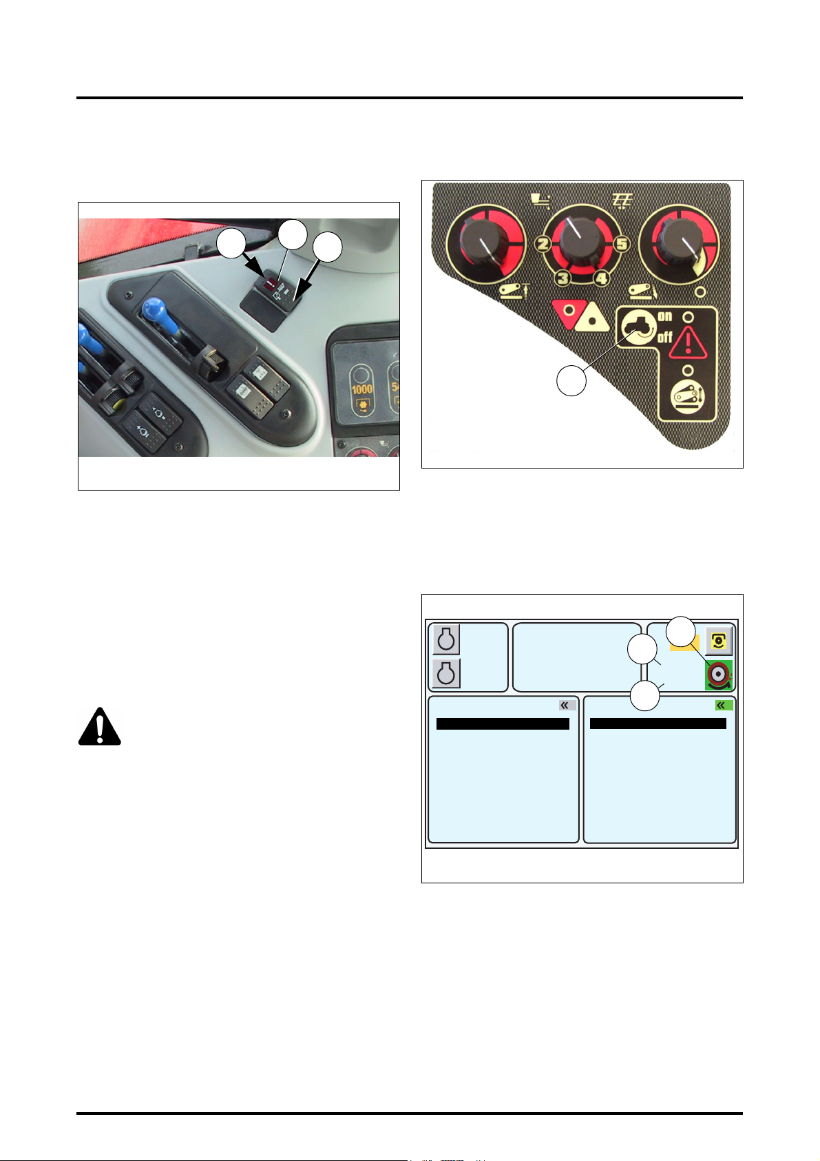
4 . OPERATION
4.9 - SUSPENDED CAB
Cab suspension flexibility can be adjusted depending on
different comfort requirements (road or field work).
1
Z3A-1042-09-04
A
2
Fig. 31
Adjustment Fig. 31:
• Road position (trailer symbol on the switch):
- Put the switch (A) in position (1) to make the suspension stiffer.
• Field position (plough symbol on the switch):
- Put the switch (A) in position (2) to make the suspension smoother.
Maintenance: See chapter 5.
4.10 - DIRECTION
CAUTION: The steering is hydrostatic type.
When the engine stops, the booster pump no
longer supplies the system. Hydrostatic steer-
ing then shifts automatically to manual operation mode which requires greater effort when turning
the steering wheel. This mechanism therefore ensures
safe operation in all conditions of use. However, no
hydraulic system can operate correctly unless:
- it is correctly maintained and the approved oils
used,
- the tightness of all connections, and the oil level, are
regularly checked.
switch (1 Fig. 32), the wheel slip control icon switches
to green (2 Fig. 33).
Z3A-1391-02-05
1
Fig. 32
Description (Fig. 33):
2 - Wheel slip control inactive (green icon if the function is
active)
3 - Maximum allowed wheel slip (value adjustable by
means of the DOT MATRIX)
4 - Actual tractor wheel slip
1000
A
2000
B
790
5.3
1
RPM
KPH
3
4
2
540
10% M
5%
2
EHS VALVES 1-4 EHS VALVES 1-4
GEARBOX SETTINGS
ACTIVE MEMORY
HEADLAND
REAR DUAL CTRL
FRONT DUAL CTRL
GEARBOX SETTINGS
ACTIVE MEMORY
HEADLAND
POINTS
EHS VALVES 5-6
TIC
Z3A-1392-02-05
Fig. 33
4.11 - WHEEL SLIP CONTROL
When the Datatronic 3 option is fitted, the wheel slip function is available on the tractor.
This function is used to check the depth of implements in
the soil according to the tractor wheel slip rate, when the
electronic system detects a difference between the tractor
specified and actual ground speeds.
To activate and adjust this function, see paragraph 4.5.10
Using the DOT MATRIX screen.
NOTE: This function can be activated by pressing the
4.22
8400 EAME
Page 77
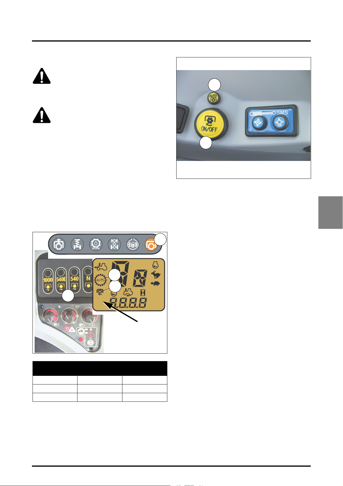
4.12 - POWER TAKE-OFF
WARNING: Always disengage the PTO before
attaching or detaching an implement or mak-
ing adjustments to it.
Take all safety precautions in any operation
involving implements driven by the PTO.
DANGER: Power take-off
Never step across any shaftline.
Do not use the tractor or trailer implement
drawbars as a step.
Never use the universal joint shaft as a footstep.
Never wear loose fitting clothes.
Remain at a safe distance from the universal joint
shaft.
4 . OPERATION
19
18
Z3A-1412-02-05
4.12.1 - Rear power take-off
The PTO can be engaged and disengaged independently of
the transmission. 540 rpm, 540E rpm and 1000 rpm
speeds can be obtained by selecting the appropriate speed
with buttons Ref. 3 (Fig. 34). The relevant display appears
on the digital display and the instrument panel indicator
light Ref.6 flashes.
Button "N" disengages the PTO if it is activated.
6
Z3A-1452-05-05
A
A
B
B
A
3
Z2-1448-05-05
PTO speed
Selected
540 rpm 540 2090 rpm
540E rpm ECO 1600 rpm
1000 rpm 1000 2030 rpm
540
1000
ECO
Z3B-147-03-05
Display
Maximum engine
KPH
MPH
RPM
Z3B-147-03-05
Fig. 34
speed
Fig. 35
• Engaging PTO in manual mode:
Press the push-button (18 Fig. 35). The PTO engaged indicator light (6 Fig. 34) stops flashing and stays permanently
on. An engaged symbol simultaneously appears on the digital display (A Fig. 34). The clutching process depends on
the length of time the push-button is pressed down:
Less than 5 seconds
Progressive starting, the PTO clutch automatically adapts
to the conditions required to start the implement.
More than 5 seconds
The speed controls and default values are deleted.
NOTE: If no speed has been preselected when the PTO
is activated, it is deactivated after a short pause and a
warning message appears on the screen.
To stop the PTO, press the push-button (18 Fig. 35) again.
• Engaging PTO in automatic mode:
This function allows the PTO to be automatically stopped
temporarily when the linkage control is in Lift position (e.g.:
Operation at headlands).
Use:
1. Press the PTO engage switch (18 Fig. 35) after having
selected a PTO speed. The PTO engaged indicator
light (6 Fig. 34) remains permanently lit.
2. Move the linkage
position.
3. Press the automatic mode engagement push-button
(19 Fig. 35). The AUTO symbol appears on the digital
display (B Fig. 34).
As soon as the linkage is in Lift position, the PTO automatically stops and the indicator light (6 Fig. 34) flashes.
As soon as the linkage returns to the Lower position, the
PTO is automatically activated and the indicator light (6) remains permanently lit.
Lift/Lower selector
to the Lower
4
8400 EAME
NOTE: If the Lower control is not activated within
90 seconds or the ground speed increases to over
25 kph, the PTO is switched off definitively.
4.23
Page 78
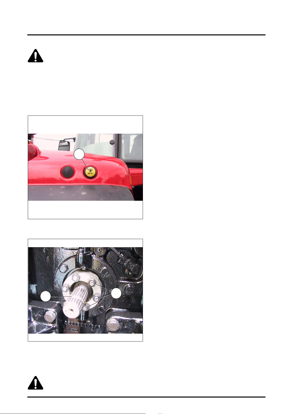
4 . OPERATION
WARNING: Always place PTO knob Ref.18 in
"OFF" position.
4.12.2 - External PTO stop button
Fig. 36: The button (G) located on the left-hand fender allows a rear PTO safety stop, and will make the instrument
panel indicator light flash.
To re-engage the power take-off, activate the button (18
Fig. 35) in the cab or the external control button (G) for 6
seconds at least.
G
Z3A-995-08-04
Fig. 36
4.12.3 - Interchangeable shaft end-fitting (flanged shaft)
A
Z3A-714-07-04
B
Fig. 37
End-fittings that can be mounted:
PTO end-fitting with 21 x 1 3/8" splines
PTO end-fitting with 6 x 1 3/4" splines
PTO end-fitting with 20 x 1 3/4" splines
CAUTION: When changing the spacer (A), the
Allen screws (B) must be tightened to a
torque of 115 (+/-15) Nm.
4.24
8400 EAME
Page 79

4 . OPERATION
Z3A-1391-02- 05
C
B
D
K
I
G
H
M
F
J
4
E
A
Z3A-773-07-04
4.13 - ELECTRONIC LINKAGE
(Fig. 38)
A. Height / depth setting knob
B. Function selector knob: Position / Intermix / Draft
C. Maximum lift height setting knob
D. Manual or automatic lowering speed setting knob
E. Lift / Lower selector switch with "neutral" position.
F. Active transport control system knob
G. Linkage lowering indicator light
H. Linkage lifting indicator light
I. Console locking and malfunction self-diagnostic indi-
cator light.
J. Active transport control system indicator light
K. Lowering speed automatic control indicator light
L. Quick soil engagement
M. Active wheel slip control
L
N. Linkage console locking indicator light (Fig. 39)
WORK
1
SETTINGS
2
EHS VALVES
3
Z3A-893-03-05
HEADLAND
4
MEMORIES/
JOBS
DUAL CTRL
5
N
1
2
3
4
5
6
ESC
Fig. 38
Fig. 39
8400 EAME
4.25
Page 80
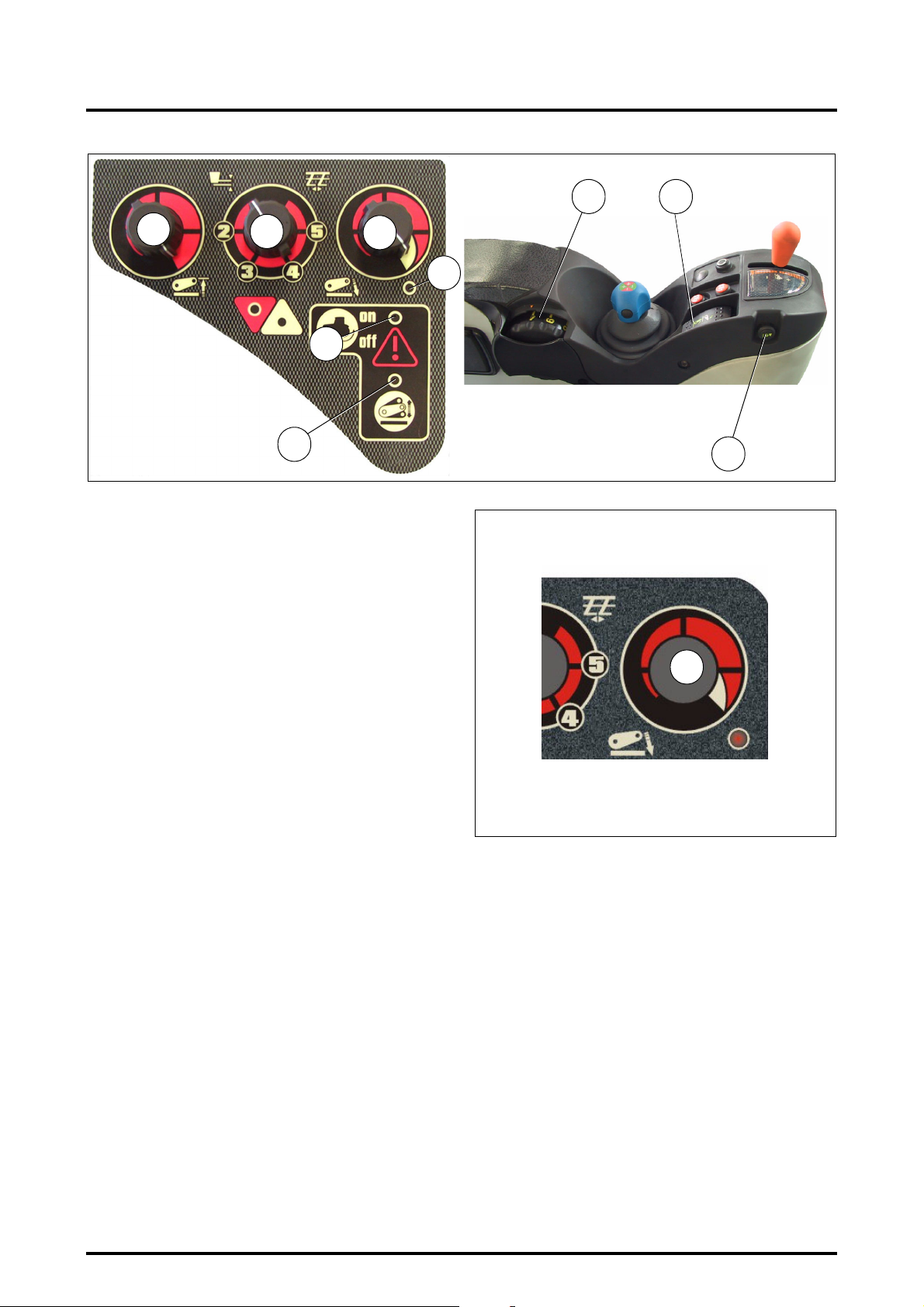
4 . OPERATION
A E
C
Z3A-1391-02-05
B
D
I
J
4.13.1 - Attaching an implement from the driver’s
seat
Start the engine. Indicator lights (I), (J) and (K) come on.
- ((K) and (J) light up for 0.5 second approximately.
- ((I) stays on until the console is activated.
- Adjust the control knobs.
- Move the function selector knob (B Fig. 40) clockwise to
minimum control position.
- Move the Lift / Lower selector switch (E) to the lift posi-
tion.
- Adjust the linkage height in turning the control knob (A).
- The Lift indicator light (H) comes on.
K
Z3A-773-07-04
L
Fig. 40
3
2
D
1
4
4.13.2 - Lowering
To lower the linkage, turn knob (A) clockwise. The lowering
indicator light (G) will come on.
In automatic mode, lowering speed is governed by two parameters: the weight of the implement and ground speed.
The indicator light K comes on when this mode is selected.
Legend Fig. 41:
1. Lowering lock position
2. Lowering speed slow
3. Lowering speed fast
4. Automatic mode
Z2-479-05-03
Fig. 41
4.13.3 - Lifting
To lift the linkage turn the knob (A) anti-clockwise.
The Lift indicator light (H) comes on.
4.13.4 - Depth control
Knob (A) in position 1 (min.) to 7 (max.) determines the
depth of work.
In position 8 and 9 the linkage is in floating mode.
4.26
8400 EAME
Page 81
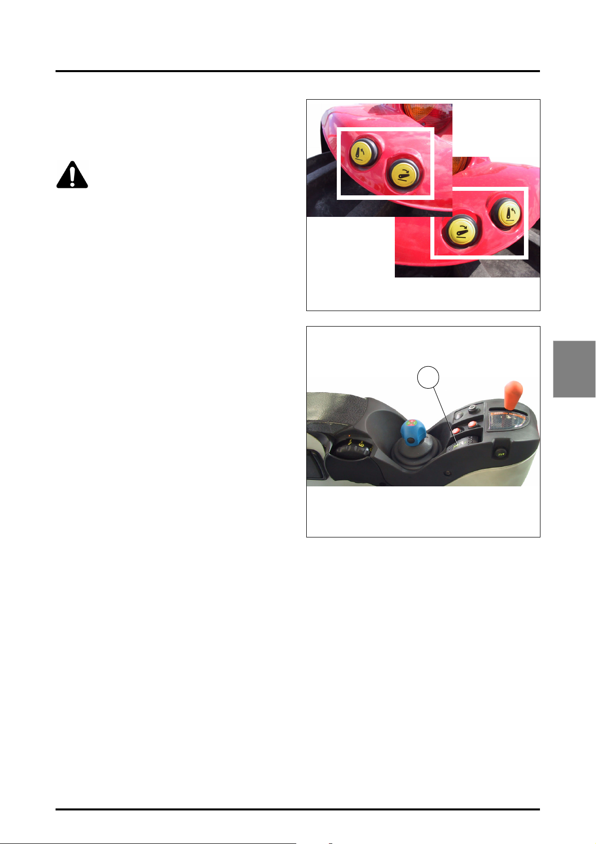
4.13.5 - Attaching an implement using external con-
trols
To use the external controls (Fig. 42) the Lift / Lower selector switch (E) must be in Neutral or Lower position.
DANGER: Always place gear shift lever and
PowerShuttle control lever in NEUTRAL
before leaving driver’s seat.
Activate the "ParkLock" brake control.
4 . OPERATION
When selector switch (E) is in the Neutral or Down position, pressing the external control buttons will cause the
linkage to be raised or lowered.
NOTE: The movement of the lift arms stops as soon as
the button is released.
When the external control is used, the lowering speed
is 70% of the maximum speed (the speed setting D
does not operate).
For safety, when the external buttons are operated, the cab
control console is automatically switched off.
To switch the cab console controls back on, press on the
selector switch (E Fig. 43).
Z2-480-05-03
Z3A-773-07-04
Z2-481-05-03
Fig. 42
E
4
Fig. 43
8400 EAME
4.27
Page 82
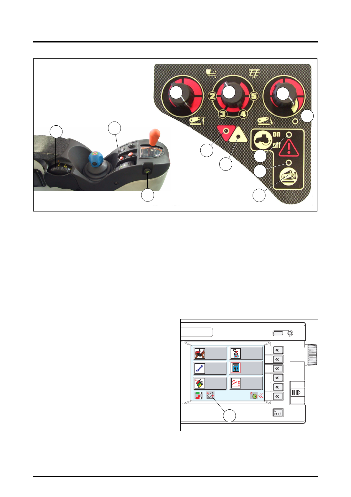
4 . OPERATION
Z2-476-05-03
Z3A-1391-02-05
A
Z3A-773-07-04
E
L
4.13.6 - Transport
- Select the minimum position with the knob (B Fig. 44).
- Adjust the maximum linkage height according to the
transport implement using the height setting knob (C).
Start from minimum position.
Move the knob (D) to position 1 (padlock).
4.13.7 - Activate transport control system
- The system operates automatically when button (F) is
pressed; indicator light J comes on.
- To deactivate this function, button (F) must be pressed.
4.13.8 - Quick soil engagement
- Move the selector switch (E) to Lowering position,
press and hold button (L) to trigger quick soil engagement.
- Release as soon as the plough is engaged into the soil.
C
B
D
G
I
H
J
F
Fig. 44
(E) into “Lower”. The depth settings previously made will
be repeated.
NOTE: A safety cut-out puts the linkage system out of
operation when the ignition is switched off, the engine
stopped (ignition switched off), or external controls are
used.
The object of this device is to avoid any accidental movement of the linkage if settings on the console have been altered, while the tractor is stationary.
To reactivate the linkage, move the switch (E) to the intermediate position, then to the lift position. Linkage is then
brought back into operation and the padlock (N Fig. 45) in
the Datatronic 3 window disappears, if this latter has been
installed.
K
4.13.9 - Use when working
- Adjust the maximum high position using knob (C).
- Using knob (D), adjust a maximum linkage lowering
speed.
- Choose the implement control mode (Draft, Position or
Intermix Control), according to the implement, the
ground conditions and the type of work, by activating
the control selector knob (B).
- Adjust the working depth using knob (A).
- The Lift and Lower indicator lights (H) and (G) allow to
display the work being carried out.
4.13.10 - Operation at headlands
Put the Lift / Lower selector switch (E) into the Lift position.
The linkage will rise to the preselected maximum lift position (C).
In order to resume work, put the Lift/Lower selector switch
4.28
Z3A-893-03-05
WORK
SETTINGS
EHS VALVES
HEADLAND
MEMORIES/
JOBS
4
5
1
2
DUAL CTRL
3
1
2
3
4
5
6
ESC
N
Fig. 45
8400 EAME
Page 83
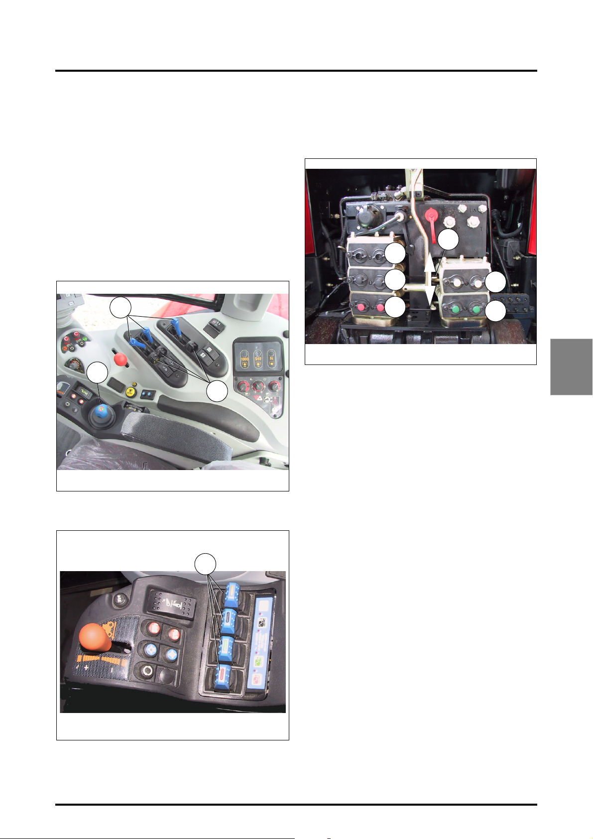
4 . OPERATION
Before reactivating the ELC calculator, ensure that settings
(A) (depth) and (C) (selection) cannot cause any dangerous
movements of the drawbars.
4.14 - AUXILIARY HYDRAULICS
4.14.1 - General
Tractors are designed to be fitted with up to 5 spool valves.
Types of control (Fig. 46; Fig. 47):
The Bosch SB23 electrohydraulic spool valves are controlled by a control lever inside the cab (A), or by a "Joystick B"
located on the armrest or by SMS control fingers
(FingerTIP D) which control the spool valves.
A
B
C
4.14.2 - Hose connection
A colour on the lock control of each lever (C ) along with the
Joystick colours, correspond to the colours on the cover of
each auxiliary spool valve (Fig. 48).
6
5
3
1
Z3A-783-08-04
Colours:
1. Red
2. Green
3. Black
4. Yellow
5. Blue
4
2
Fig. 48
4
Z3A-784-08-04
Z4A-1647-11-05
IMPORTANT: The two hoses of one ram must be con-
Fig. 46
D
nected on the same auxiliary spool valve.
To facilitate disconnecting a hose, move the lever (6) up
down. This will reduce the pressure in the circuit.
Additional spool valve outlets (Fig. 49):
Four additional sockets are provided for cases where the
hitched implement needs to use other spool valves:
1. Direct outlet pressure
2. Rear axle return
3. XLS line
4. Rear axle free return
Fig. 47
8400 EAME
4.29
Page 84
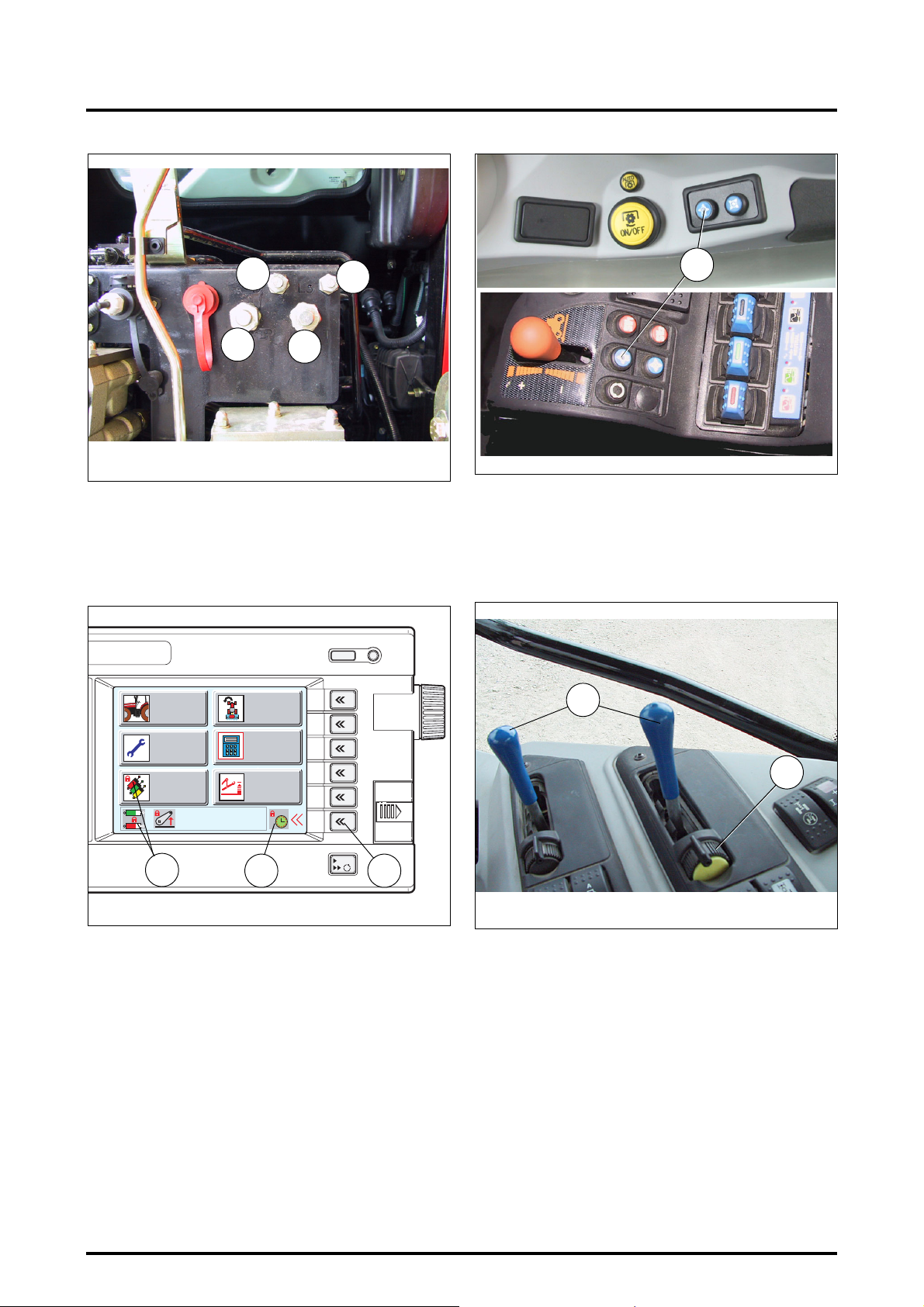
4 . OPERATION
Z3A-752-07-04
Z3A-754-07-04
4
1
2
3
Fig. 49
4.14.3 - Unlocking hydraulic spool valve controls
When the tractor is started, the spool valve controls cannot
be used. For this reason two padlocks are displayed on the
first Datatronic 3 screen when the tractor is fitted with this
option.
WORK
1
SETTINGS
2
EHS VALVES
3
HEADLAND
MEMORIES/
JOBS
DUAL CTRL
1
4
5
2
3
4
5
6
4
Z4A-1647-11-05
4.14.4 - Using the control levers (Fig. 52)
Each spool valve controlled by a lever (A), can be blocked
in various positions by actuating the lock (D):
• Neutral position (Fig. 52)
Fig. 51
A
D
ESC
3
Fig. 50
Z3A-893-03-05
1
2
1. Locking the hydraulic spool valve controls To unlock,
press the button (4 Fig. 51) (the padlock disappears
and the button indicator light goes out).
2. Locking the spool valve activation times. To unlock,
«
press the key
(3 Fig. 50) (the padlock disappears).
6
NOTE: If the tractor is not fitted with the Datatronic 3,
press only button 4 to unlock. The button indicator light
goes out.
4.30
Z3A-821-08-04
Fig. 52
• Ram rod extension position (for example: Fig. 53)
8400 EAME
Page 85
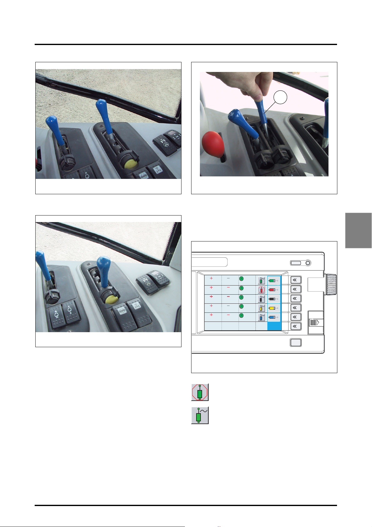
4 . OPERATION
E
Z3A-822-08-04
Fig. 53
• Ram rod retraction position (for example: Fig. 54)
Z3A-823-08-04
Fig. 54
• Floating position (Fig. 55)
To activate the floating position, push the lever to its maximum position (E), then release it. The lever returns to its in-
itial position, while the spool valve is in floating position.
To deactivate the floating position, move the lever to any
position. The spool valve switches to neutral position.
Z3 A-10 01-0 8-0 4
Fig. 55
NOTE: If the tractor is fitted with the Datatronic 3,
ensure that the "Floating" function is available for each
spool valve (Fig. 56). To activate this function, see
chapter 7, section 7.8.
100%
100%
100%
100%
100%
Z3A-1008-08-04
100%
100%
100%
100%
100%
0s
STOP
0s
0s
0s
0s
1
2
3
4
5
6
ESC
Fig. 56
STOP
Floating position unavailable
4
8400 EAME
Floating position available
4.31
Page 86
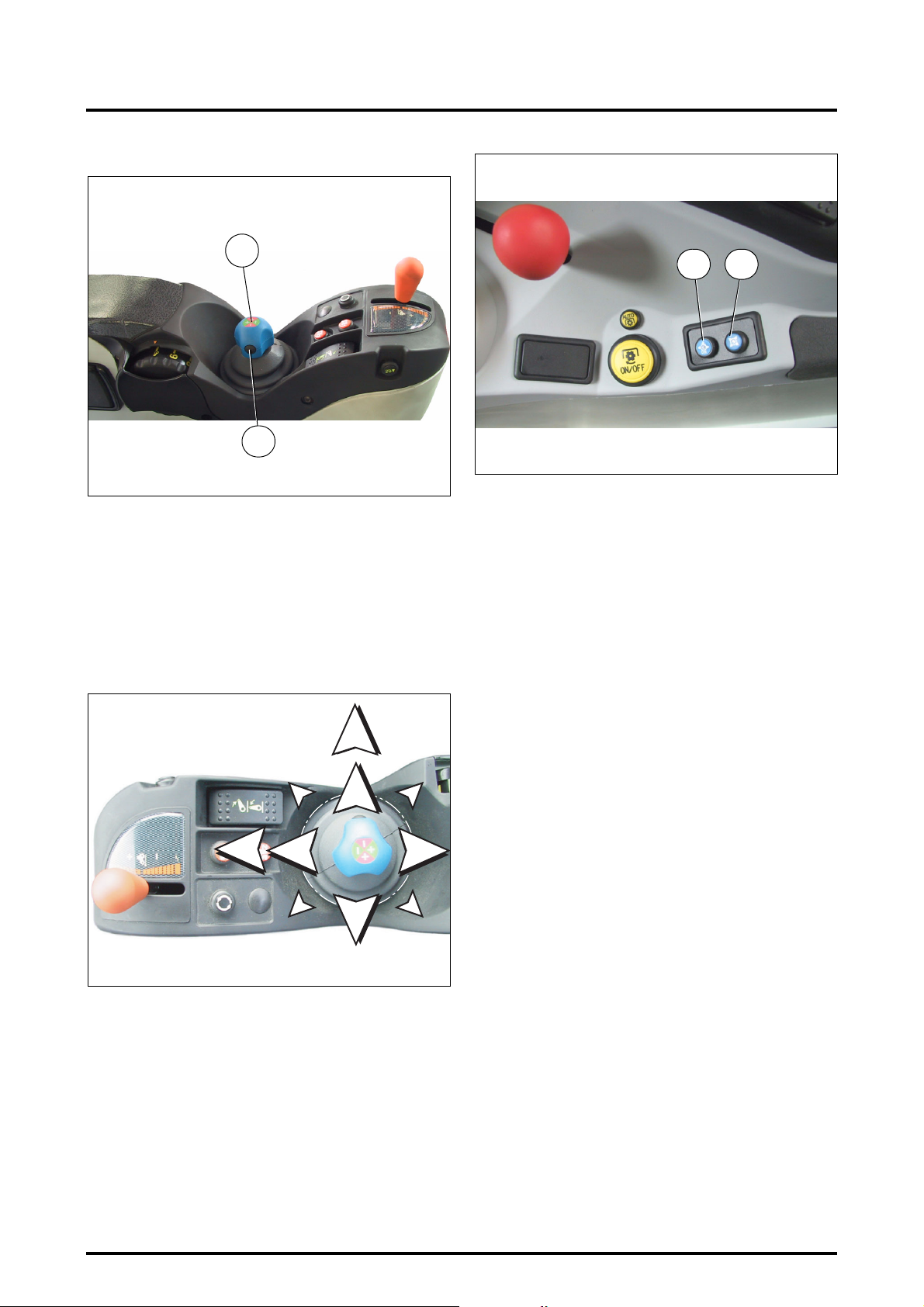
4 . OPERATION
4.14.5 - "SMS" controlled by Joystick
1
Z3A-773-07-04
2
Fig. 57
1. 4-function control Joystick (separate or combined).
Description (Fig. 58):
A - Lift
B - Lower
C - Empty (bucket)
D - Fill (bucket)
2. Extra function control button (2 Fig. 57), e.g.: bucket
(open/close jaws). To use this function, press the but-
ton and move the Joystick towards C or D.
C1
C
B1
B
A
D
Z3A-756-07-04
Z3A-756-07-04
Fig. 58
BA
Z3A-752-07-04
Fig. 59
4.14.6 - Memorising a flow rate
NOTE: If the tractor is fitted with the DATATRONIC 3,
see chapter 7 in the EHS VALVES application for storing
flow and activation time values for each spool valve.
This function memorises a flow rate (for example 30% of a
spool valve maximum flow rate). Next, when the control is
activated, the flow generated shall be that of the stored value.
When the engine is started, the spool valve controls are unavailable and the button red indicator light (A ) is lit.
1. Press the button (A) to make the spool valve controls
available. The red indicator light comes out.
2. Move and hold the Joystick in the desired direction to
obtain the desired flow, the flow stops as soon as the
joystick is released.
3. By moving the joystick to its limit of travel beyond its
locked B1 / C1 floating position, and releasing immediately, the flow is automated, and when in OFF position
the “~” icon is displayed on the lower screen.
Operation:
• When using a control and whatever the position used,
the flow rate generated shall be that which was previously memorised.
• To cancel the values, press button (B Fig. 59) for approx-
imately 5 seconds (default value 100%).
3. Flow rate memorisation or memorised flow rate reset
(B Fig. 59).
4. Spool valve control ON/OFF control (A Fig. 59).
4.32
4.14.7 - Setting joystick parameters
• For a correct use of Datatronic 3, refer to chapter 7.
Setting the flow rate (Versions without Datatronic 3)
(Fig. 60)
1. Joystick in neutral position: the float position cannot be
used, the hydraulic flow is at its maximum.
Joystick in any other position: move the Joystick in the
desired direction(s) and briefly press button 9, to memorise the flow rate.
If a stored flow rate must be changed or cancelled,
operate the joystick then press the Memory key (9.
Fig. 60) for 5 seconds to restore the maximum flow
rate.
8400 EAME
Page 87
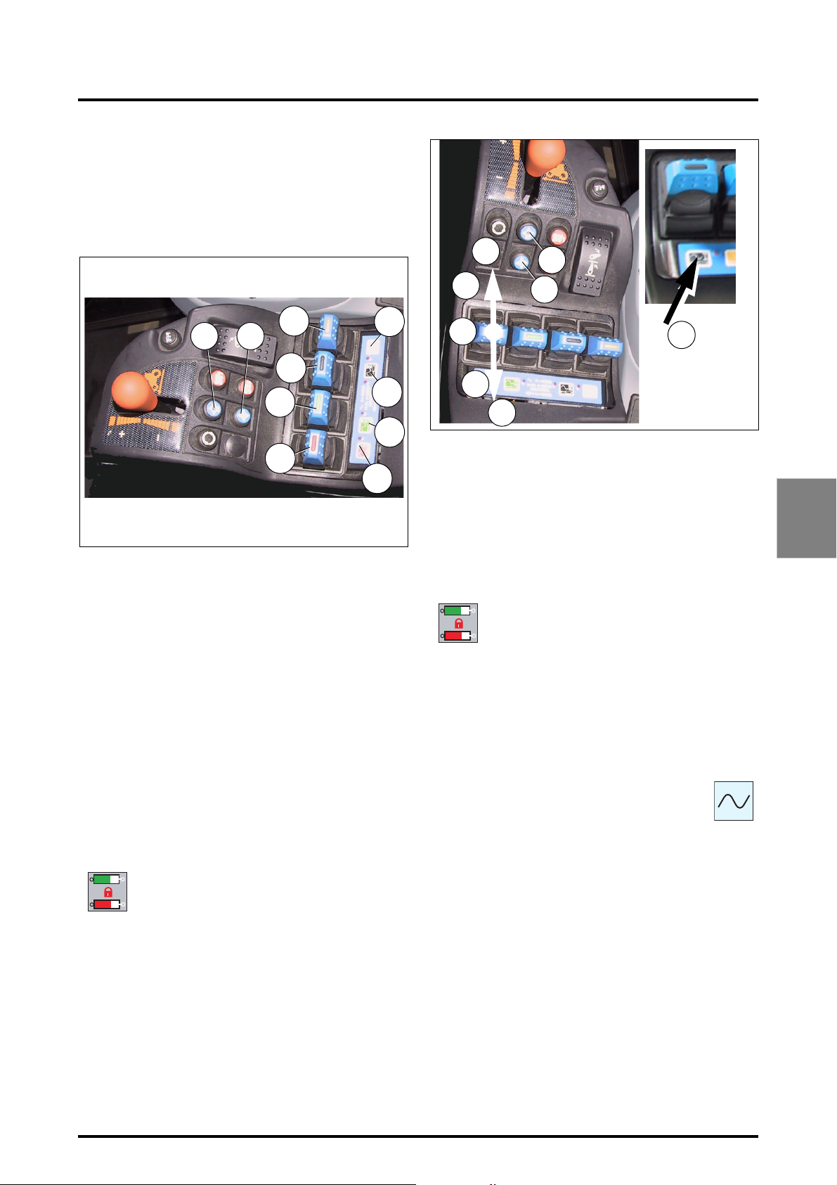
All the pre-recorded flow parameters can be reset simultaneously by pressing memory button (9. Fig. 60) for approximately 5 seconds when the Joystick is in the neutral
position, the indicator light 4flashes during this time.
4.14.8 - "SMS" control (FingerTIP)
4 . OPERATION
7
8
910
5
3
6
4
1
2
Z4A-1647-11-05
Fig. 60
4.14.8.1 - Description
1. 1st spool valve "SMS" control (red).
2. 1st spool valve constant flow switch and indicator
light.
3. 2nd spool valve "SMS" control (green).
4. 2nd spool valve constant flow switch and indicator
light.
5. 3rd spool valve "SMS" control (black).
6. 3rd spool valve constant flow switch and indicator
light.
7. 4th spool valve "SMS" control (yellow).
8. 4th spool valve constant flow switch and indicator
light.
9. Flow rate memorisation or memorised flow rate reset
10. Spool valve ON / OFF control.
4.14.8.2 - Using the "SMS" controls
Unlock the spool valve controls (see paragraph 4.14.3).
D
B
A
C
D
4.14.8.3 - Memorising a flow rate
NOTE: If the tractor is fitted with the DATATRONIC 3,
see chapter 7 in the EHS VALVES application for storing
flow and activation time values for each spool valve.
When the engine is started, the spool valve controls are unavailable and the red indicator light of button 10 is lit.
When the Datatronic 3 has been installed, the
corresponding settings in the active window
are locked (lock icon displayed).
1. Press button 10 to make the EHS controls operational,
the red indicator light goes out, (on the optional
Datatronic 3 fitted the lock icons disappear from the
screen), adjustment of the Datatronic 3 is now possible.
2. Move and hold an EHS control in the desired direction
to obtain the desired flow, the flow stops as soon as
the Joystick is released.
3. Move the "Joystick” control to position B1/C1
and release it immediately to obtain floating
position, and the flow rate is automated (the
icon is displayed on the Datatronic 3 screen).
4. Still holding the control in the required position, press
the memory key 9 for one second. The flow rate is
memorised.
10
9
11
Z4A-1647-11-05
Fig. 61
4
Fig. 61:
A. Neutral position
B. Ram rod retracted position
C. Ram rod extended position
D. Control locking position: for each of the control spool
valves, locked position is obtained by pushing the lever
to its maximum.
11. Spool valve constant flow position switches (Kick out)
Move the "SMS" control to locked position (
the switch that corresponds to its colour (matching colours). The red indicator light should come on.
8400 EAME
D) and press
NOTE: When using a control and whatever the position
used, the flow rate generated shall be that which was
previously memorised. To cancel the values, press the
button (9 Fig. 61) for approximately 5 seconds (default
value 100%).
4.14.9 - Emergency manual spool valve control
In case of malfunction of the Joystick or spool valve controls, the emergency hand controls are available to lift or
lower the installed attachments.
Button 10 (ON/OFF Fig. 61) flashes and the relevant error
code is displayed on the tractor performance monitor (if installed).
4.33
Page 88
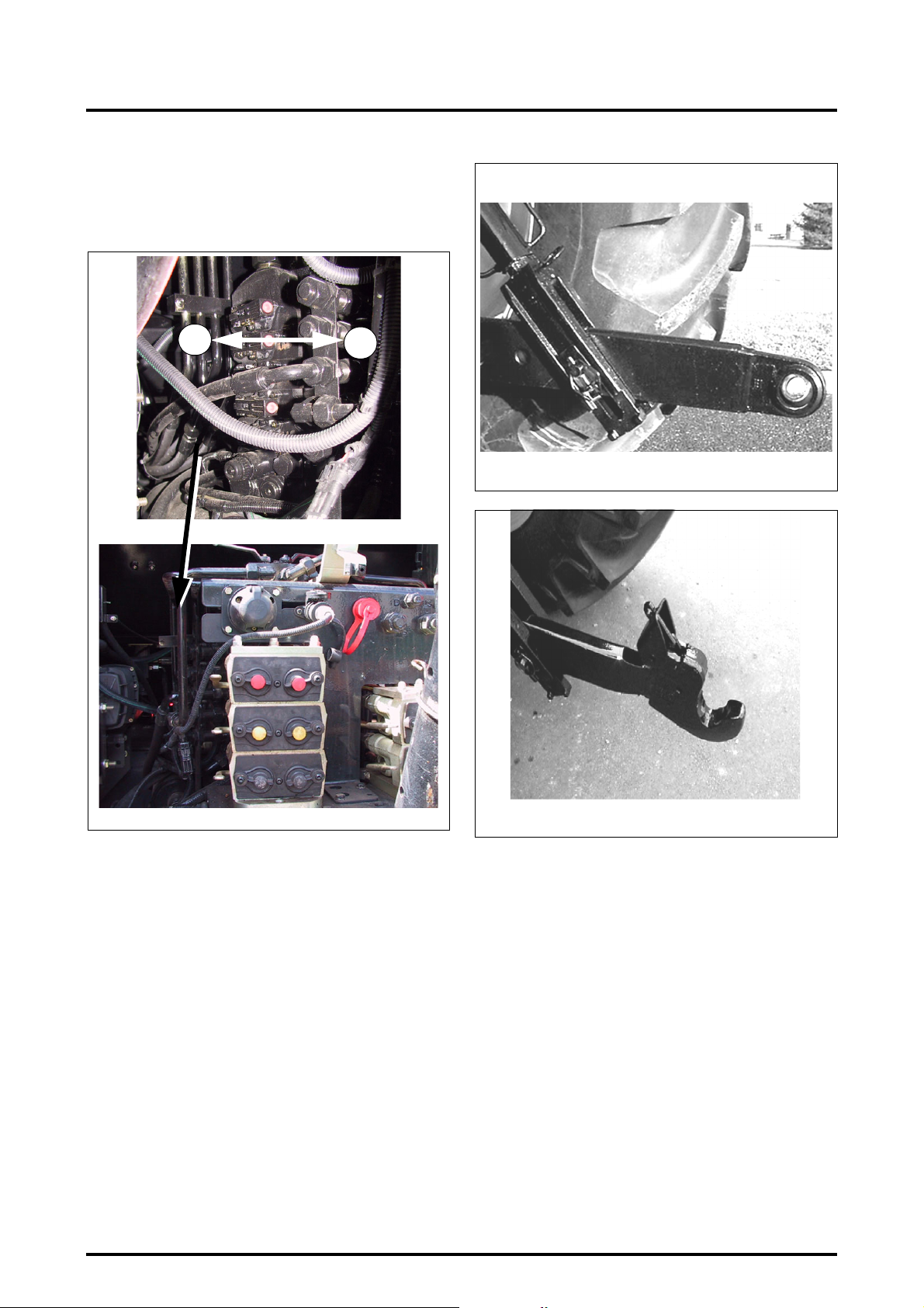
4 . OPERATION
Operation: Move one of the levers on the spool valves by
pressing as shown (1) to lower or by pulling as shown (2)
to lift (Fig. 62).
Stop the engine, then restart it in order to reactivate the
Joystick.
Z3A-755-07-04
2
1
V571
Fig. 63
Z3A-972-08-04
Fig. 62
4.15 - THREE-POINT LINKAGE
IMPORTANT: To prevent rear linkage damage when
operating trailed attachments, care should be taken
when turning to prevent the implement from fouling
the linkage.
4.15.1 - Linkage
The tractor is supplied eitherwith Category 3 ball joint linkage or with optional category 3 fast linkage hitches.
4.15.2 - Lower links
• Fixed ball end type (Fig. 63)
• Hook and ball type (Fig. 64)
The hooks engage automatically in the ball joints which are
fitted to the hitch pins. The normal balls are used for clevisend linkage; the balls with guide cones are used for single
pin linkage. Ensure the linkage is properly locked.
The hooks can be unlocked for uncoupling from the cab,
using cables (accessory).
V538
Fig. 64
4.15.3 - Lift rods
(Fig. 65)
The lift rods are fitted with a port (1) allowing for floating position when the pin (2) is in position (3) (for large imple-
ments or implements with a depth wheel).
A fixed low position (4) can be obtained by moving the pin
(2).
4.34
8400 EAME
Page 89
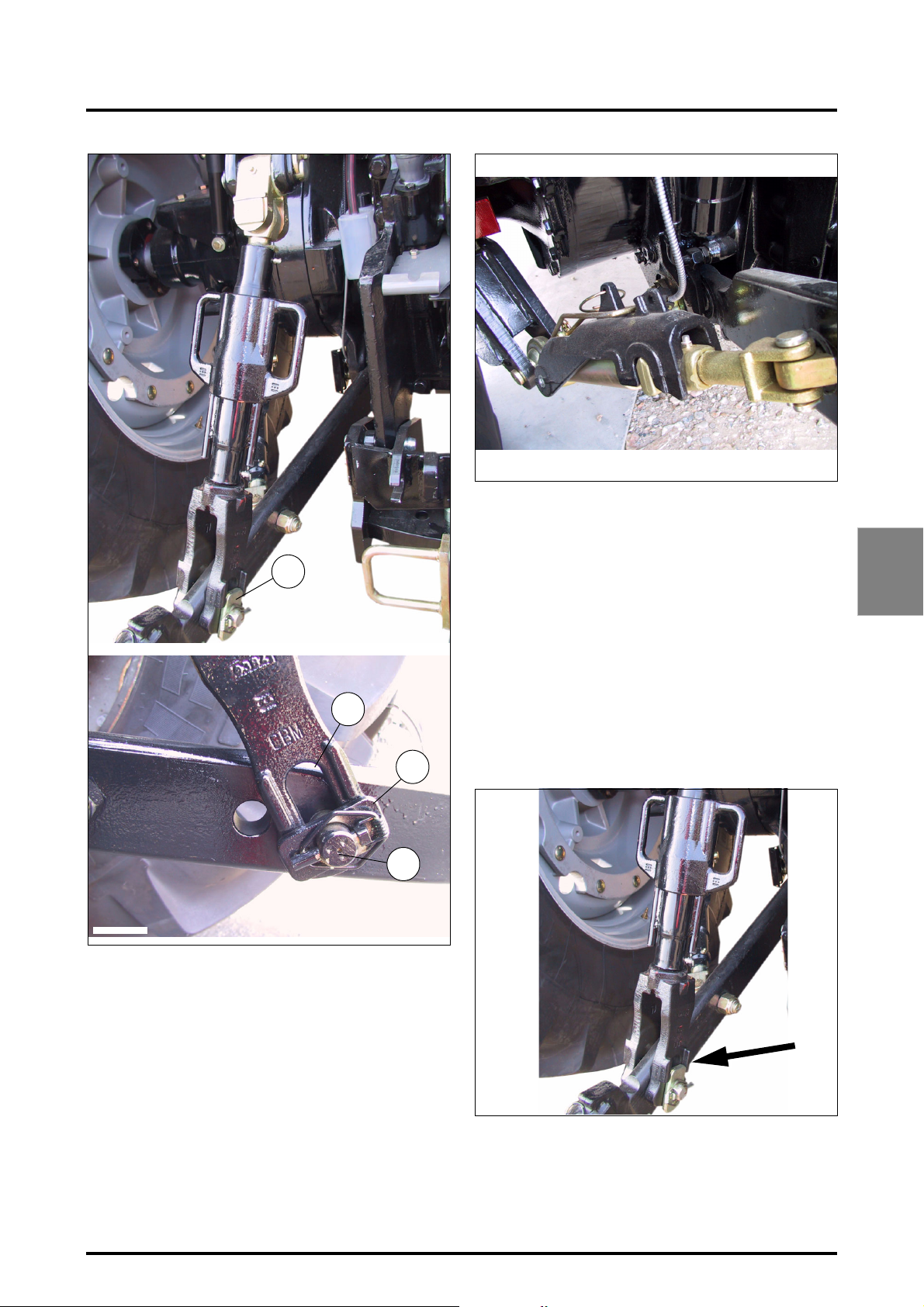
4 . OPERATION
Z3A-703-07-04
4.15.4.1 - Adjustment procedures
Once the suitable position has been determined according
to implements used, adjustment of stabilizers should be
3
Z2-493-05-03
1
4
carried out as follows:
• Pos. 1: Screw or unscrew centre members to obtain
desired left-hand side/right-hand side sway.
• Pos. 2: Automatic no-sway at transport position.
NOTE: The side sway is to be adjusted with drawbars in
transport position.
A. Install Cat. 3 linkage drawbars.
B. Set lift rods length as required.
C. Set lower link travel as shown (Fig. 67).
D. Fully screw in stabilisers.
E. Start the engine.
Fig. 66
4
2
Z3A-1128-09-04
4.15.4 - Stabilisers
Stabilisers are used to limit the lateral movement of the
lower links.
The front stabiliser support has only one possible position
(Fig. 66).
8400 EAME
Fig. 65
Z3A-1129-09-04
F. Set the control panel hitch "Lift/Lower" switch to "Lift"
then to "Neutral".
G. Press "Lift" button until lower links reach highest posi-
tion.
H. Stop the engine.
Fig. 67
4.35
Page 90
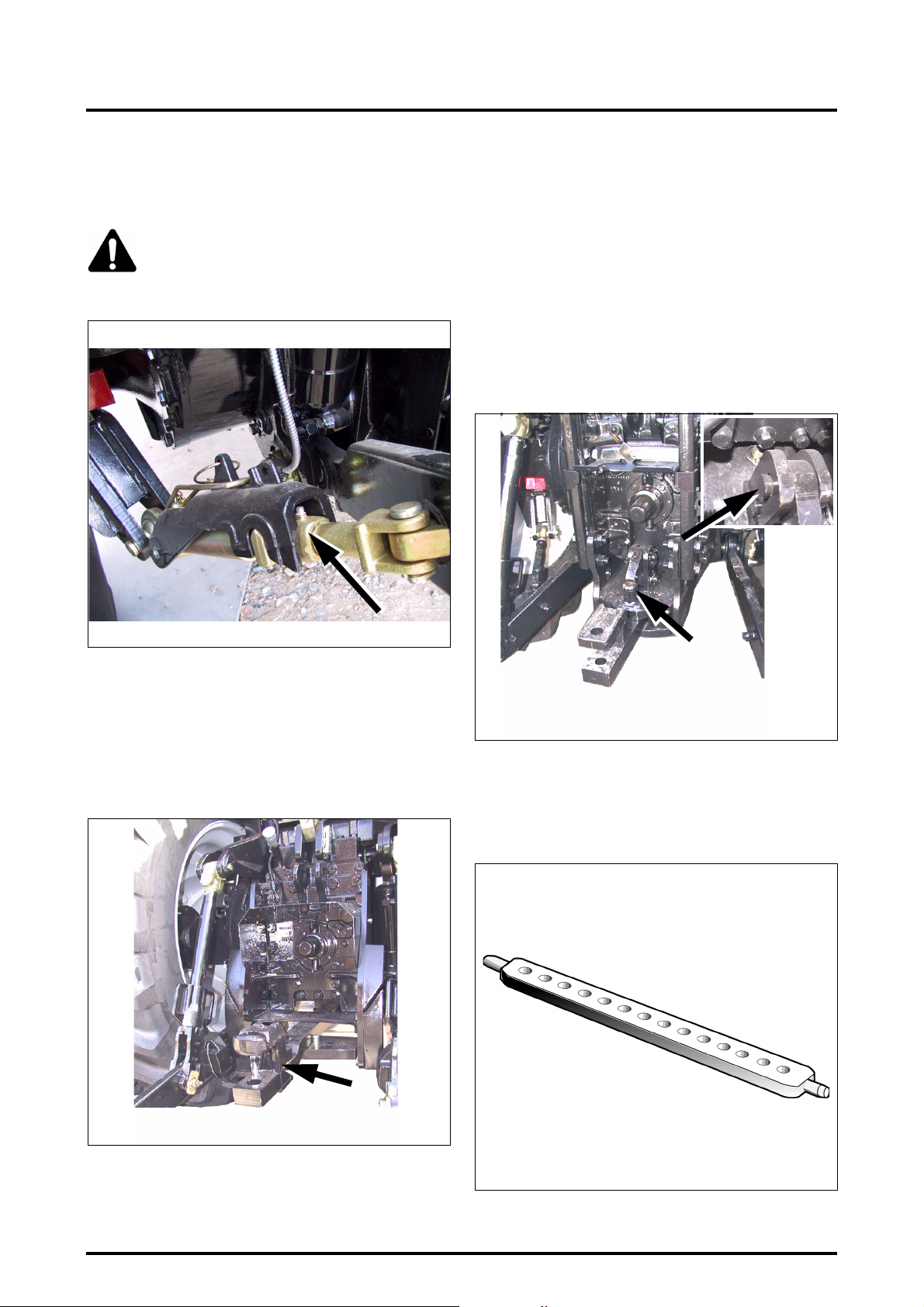
4 . OPERATION
I. Unscrew stabilisers (Fig. 68) until drawbars have no lat-
eral oscillation and are centred.
J. Screw both stabilisers in 1 turn.
CAUTION: Increasing transport height, modifying
lift rods length or fixing position of lift rods on
drawbars once the above adjustments are completed will result in stabiliser damage.
- Refit the clevis pins and secure them with the clips to
hold the drawbar in the required position.
Maximum tractable weight: 13000 Kg.
Maximum vertical load at hitch: 1700 Kg.
4.16.2 - Closed eye bolt for balanced full trailer
Suitable for heavy trailers which transfer heavy load to the
tractor (Fig. 70).
It is welded to the frame of the swinging drawbar and has
a safety retaining latch.
Maximum vertical load: 3000 Kg.
Z3A-1237-11-04
Z3A-703-07-04
4.16 - DRAWBAR AND HITCHES
Available as options, according to countries.
4.16.1 - Swinging drawbar
(Suitable for trailed implements only) (Fig. 69).
Fig. 68
Z3A-1238-11-04
Fig. 70
4.16.3 - Perforated bar
This is fitted to the lower links and is suitable for light loads
charges (Fig. 71).
Z3A-1236-11-04
Setting the offset:
- Remove the clips and take out the clevis pins.
- Position the drawbar as required.
4.36
Z2-582
Fig. 69
Fig. 71
8400 EAME
Page 91
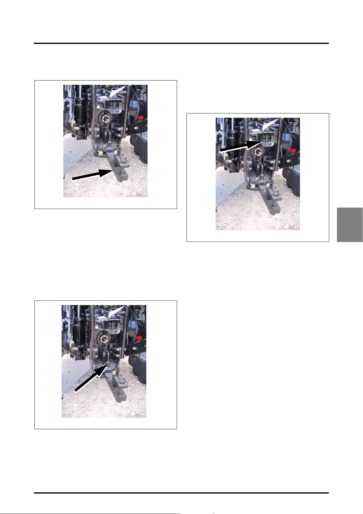
4 . OPERATION
4.16.4 - Swinging drawbar
(Suitable for trailed implements only) (Fig. 69).
Z3A-716-07-04
Setting the offset:
- Remove the clips and take out the clevis pins.
- Position the drawbar as required.
- Refit the clevis pins and secure them with the clips to
hold the drawbar in the required position.
Maximum tractable weight: 13000 Kg.
Maximum vertical load at hitch: 1700 Kg.
4.16.5 - Closed eye bolt for balanced full trailer
Suitable for heavy trailers which transfer heavy load to the
tractor (Fig. 70).
Fig. 72
4.16.6 - Roller type swinging drawbar
This drawbar is used with very heavy trailed implements. It
makes sharp turns at the headland easier, by allowing the
drawbar to swing with the implement.
4.16.7 - Fast setting clevis for 4-wheel type trailer
Z3A-716-07-04
To adjust the height of the clevis, pull the lever sideways,
to disengage the locking mechanism. The clevis can then
be moved up or down to the required position (Fig. 74).
Release the lever to lock the clevis.
Maximum tractable weight: 25100 Kg
Maximum vertical load at hitch: 1800 Kg
Fig. 74
4
Z3A-716-07-04
It is welded to the frame of the swinging drawbar and has
a safety retaining latch.
Maximum vertical load: 3000 Kg
8400 EAME
Fig. 73
4.37
Page 92
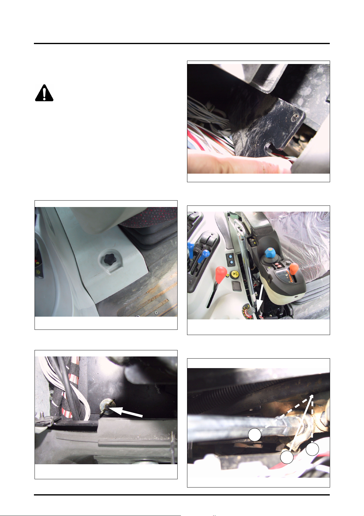
4 . OPERATION
4.17 - TOWING PROCEDURE AND INSTRUCTIONS
WARNING: Towing: the following instructions must be followed when towing:
If the engine is not running:
• Maximum towing speed: 10 kph.
• Maximum towing distance: 8 km.
If the engine is running:
• Towing speed is identical to that of a trailer without
brakes at the speed authorised by legislation in force in
the country concerned.
Towing procedure:
1. Open the cover located on the cab floor (right-hand
side) (Fig. 75).
Z2-599-05-03
Fig. 77
3. Position the emergency lever on the control unit (C)
(Fig. 78).
Z2-597-05-03
Fig. 75
2. Remove the protective shield (Fig. 76 and Fig. 77).
Z3A-777-07-04
Fig. 76
Z3A-741-07-04
Fig. 78
4. Move the Dyna VT transmission to neutral position
(middle position Ref. 1 Fig. 79).
2
3
1
Z2-601-07-03
Fig. 79
4.38
8400 EAME
Page 93
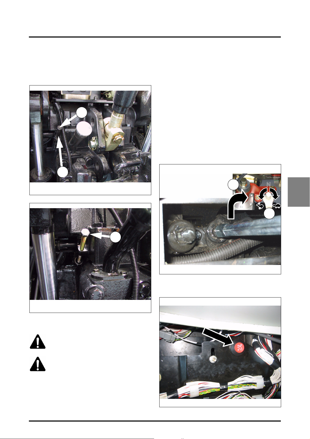
4 . OPERATION
5. Release the “ParkLock” parking brake. For this purpose:
- take off the spacer (Ref. 4 Fig. 80) after removing the
screw Ref. 5,
- refit and tighten the screw Ref. 5 and tighten (Fig. 81).
5
4
Z3A-762-07-04
Fig. 80
range, maximum speed is 15 kph in forward position and
11 kph in reverse position.
1. Stop the engine if it is running.
2. Open the cover located on the cab floor (right-hand
side) (Fig. 75).
3. Remove the protective shield (Fig. 76 and Fig. 77).
4. Position the limp home lever on the range control (Ref.
2 Fig. 82) and select the limp home range:
- clockwise direction, tortoise range,
- anti-clockwise direction, hare range.
NOTE: The maximum speed when shifting range is 2 kph.
IMPORTANT: When shifting range, only use the supplied limp home lever supplied with the tractor,
because the coupling mechanism in the control unit
could be damaged (maximum allowed torque 10 Nm).
1
4
5
Z3A-778-07-04
Fig. 81
4.17.1 - Limp home mode
DANGER: When the tractor is stopped, the
gear range must be in neutral position (middle position) and the brake must be engaged.
CAUTION: Once the tractor is started, the
transmission is driven totally by meshing if a
gear range (hare or tortoise) is engaged. Press
down the clutch pedal, because any transmis-
sion ratio can be selected.
If the transmission ratio control is not possible due to a
breakdown, the tractor can be driven mechanically using a
limp home lever.
Maximum speed in the “Hare” range is 34 kph in forward
position and 25 kph in reverse position. For the “Tortoise”
2
Z2-609-07-03
5. Start the tractor while pressing down the red button
(limp home button) (Fig. 83).
Z2-610-07-03
Fig. 82
Fig. 83
8400 EAME
4.39
Page 94
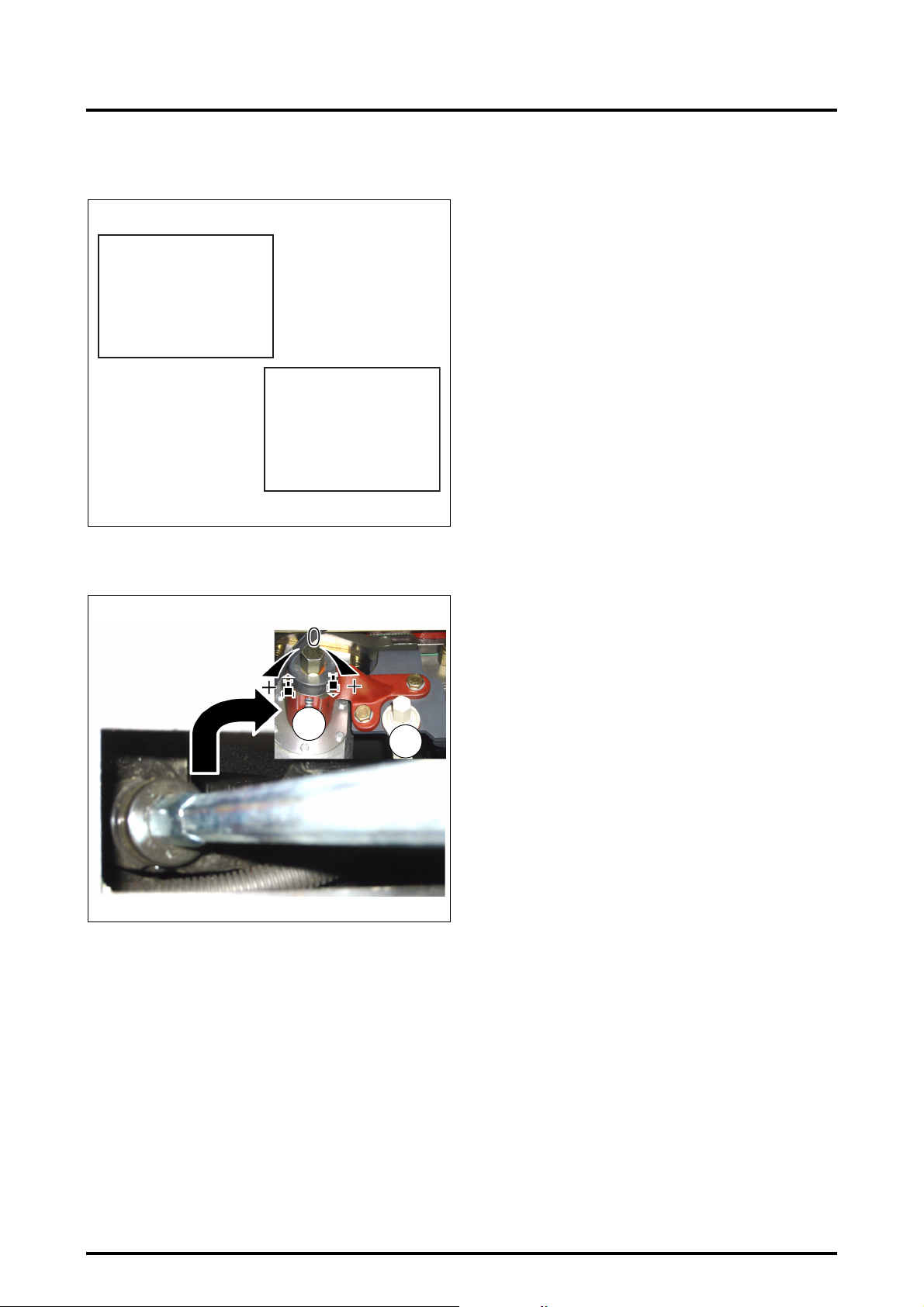
4 . OPERATION
6. One of the two error codes is displayed on the lefthand screen (DOT MATRIX) (Fig. 84).
ERROR
Code TLPH
ERROR
Code 4159
Z2-611-07-03
7. Position the limp home lever on the control (Ref. 1)
(Fig. 85).
1
Z2-612-07-03
12. Turn the lever in the required direction of travel:
- anti-clockwise direction, forward travel,
- clockwise, reverse travel.
Fig. 84
2
Fig. 85
NOTE: Travel speed depends on the rotational value of
the lever.
8. Carefully release the clutch pedal. The tractor moves in
the previously set direction of travel and manually
reaches the selected ratio.
9. To deactivate the limp home mode, stop the tractor
and switch off the ignition key.
4.40
8400 EAME
Page 95

5 . MAINTENANCE AND ADJUSTMENTS
Chapter 5
MAINTENANCE AND ADJUSTMENTS
5
8400 EAME
5.1
Page 96

Page 97

5 . MAINTENANCE AND ADJUSTMENTS
CONTENTS
5.1 - INITIAL 50 HOUR SERVICE INSPECTION . . . . . . . . . . . . . . . . . . . . . . . . . . . . . . . . . . . . . . . . . . . . . . . . . . . . .5.5
5.1.1 Engine, fuel and cooling systems . . . . . . . . . . . . . . . . . . . . . . . . . . . . . . . . . . . . . . . . . . . . . . . . . . . . .5.5
5.1.2 Electrical system and instruments . . . . . . . . . . . . . . . . . . . . . . . . . . . . . . . . . . . . . . . . . . . . . . . . . . . .5.5
5.1.3 Front axle and steering . . . . . . . . . . . . . . . . . . . . . . . . . . . . . . . . . . . . . . . . . . . . . . . . . . . . . . . . . . . . .5.5
5.1.4 Transmission and hydraulics . . . . . . . . . . . . . . . . . . . . . . . . . . . . . . . . . . . . . . . . . . . . . . . . . . . . . . . . .5.5
5.1.5 Clutches and brakes . . . . . . . . . . . . . . . . . . . . . . . . . . . . . . . . . . . . . . . . . . . . . . . . . . . . . . . . . . . . . . .5.5
5.1.6 General . . . . . . . . . . . . . . . . . . . . . . . . . . . . . . . . . . . . . . . . . . . . . . . . . . . . . . . . . . . . . . . . . . . . . . . . .5.5
5.2 - SERVICE GUIDE. . . . . . . . . . . . . . . . . . . . . . . . . . . . . . . . . . . . . . . . . . . . . . . . . . . . . . . . . . . . . . . . . . . . . . . . . .5.6
5.3 - USER GUIDE . . . . . . . . . . . . . . . . . . . . . . . . . . . . . . . . . . . . . . . . . . . . . . . . . . . . . . . . . . . . . . . . . . . . . . . . . . . .5.8
5.3.1 Engine, fuel and cooling systems . . . . . . . . . . . . . . . . . . . . . . . . . . . . . . . . . . . . . . . . . . . . . . . . . . . . .5.8
5.3.2 Electrical system and instruments . . . . . . . . . . . . . . . . . . . . . . . . . . . . . . . . . . . . . . . . . . . . . . . . . . . .5.8
5.3.3 Front axle and steering . . . . . . . . . . . . . . . . . . . . . . . . . . . . . . . . . . . . . . . . . . . . . . . . . . . . . . . . . . . . .5.8
5.3.4 Transmission and hydraulics . . . . . . . . . . . . . . . . . . . . . . . . . . . . . . . . . . . . . . . . . . . . . . . . . . . . . . . . .5.8
5.3.5 Clutch . . . . . . . . . . . . . . . . . . . . . . . . . . . . . . . . . . . . . . . . . . . . . . . . . . . . . . . . . . . . . . . . . . . . . . . . . .5.8
5.3.6 General . . . . . . . . . . . . . . . . . . . . . . . . . . . . . . . . . . . . . . . . . . . . . . . . . . . . . . . . . . . . . . . . . . . . . . . . .5.8
5.4 - APPROVED LUBRICANTS. . . . . . . . . . . . . . . . . . . . . . . . . . . . . . . . . . . . . . . . . . . . . . . . . . . . . . . . . . . . . . . . . .5.9
5.4.1 Engine oil . . . . . . . . . . . . . . . . . . . . . . . . . . . . . . . . . . . . . . . . . . . . . . . . . . . . . . . . . . . . . . . . . . . . . . . .5.9
5.4.2 Recommended SAE viscosity grades (SAE J300d) . . . . . . . . . . . . . . . . . . . . . . . . . . . . . . . . . . . . . . . .5.9
5.4.3 Coolant . . . . . . . . . . . . . . . . . . . . . . . . . . . . . . . . . . . . . . . . . . . . . . . . . . . . . . . . . . . . . . . . . . . . . . . . .5.9
5.4.4 Dyna VT transmission and auxiliary hydraulics . . . . . . . . . . . . . . . . . . . . . . . . . . . . . . . . . . . . . . . . . . .5.9
5.4.5 Rear final drive units . . . . . . . . . . . . . . . . . . . . . . . . . . . . . . . . . . . . . . . . . . . . . . . . . . . . . . . . . . . . . . .5.9
5.4.6 Clutch . . . . . . . . . . . . . . . . . . . . . . . . . . . . . . . . . . . . . . . . . . . . . . . . . . . . . . . . . . . . . . . . . . . . . . . . . .5.9
5.4.7 Front axle, front final drive units . . . . . . . . . . . . . . . . . . . . . . . . . . . . . . . . . . . . . . . . . . . . . . . . . . . . . .5.9
5.4.8 Grease nipples. . . . . . . . . . . . . . . . . . . . . . . . . . . . . . . . . . . . . . . . . . . . . . . . . . . . . . . . . . . . . . . . . . . .5.9
5.5 - INSTRUCTIONS FOR PRESSURE WASHING . . . . . . . . . . . . . . . . . . . . . . . . . . . . . . . . . . . . . . . . . . . . . . . . . .5.9
5
5.6 - LUBRICATION . . . . . . . . . . . . . . . . . . . . . . . . . . . . . . . . . . . . . . . . . . . . . . . . . . . . . . . . . . . . . . . . . . . . . . . . . .5.10
5.6.1 Lubrication points . . . . . . . . . . . . . . . . . . . . . . . . . . . . . . . . . . . . . . . . . . . . . . . . . . . . . . . . . . . . . . . .5.10
5.7 - ENGINE. . . . . . . . . . . . . . . . . . . . . . . . . . . . . . . . . . . . . . . . . . . . . . . . . . . . . . . . . . . . . . . . . . . . . . . . . . . . . . . .5.14
5.7.1 6-cylinder engine . . . . . . . . . . . . . . . . . . . . . . . . . . . . . . . . . . . . . . . . . . . . . . . . . . . . . . . . . . . . . . . . .5.14
5.7.2 Oil level . . . . . . . . . . . . . . . . . . . . . . . . . . . . . . . . . . . . . . . . . . . . . . . . . . . . . . . . . . . . . . . . . . . . . . . .5.15
5.7.3 Drain the engine oil every 400 hours. . . . . . . . . . . . . . . . . . . . . . . . . . . . . . . . . . . . . . . . . . . . . . . . . .5.15
5.7.4 Change the engine oil filter every 400 hours. . . . . . . . . . . . . . . . . . . . . . . . . . . . . . . . . . . . . . . . . . . .5.15
5.8 - FUEL SYSTEM . . . . . . . . . . . . . . . . . . . . . . . . . . . . . . . . . . . . . . . . . . . . . . . . . . . . . . . . . . . . . . . . . . . . . . . . . .5.15
5.8.1 Fuel pre-filter . . . . . . . . . . . . . . . . . . . . . . . . . . . . . . . . . . . . . . . . . . . . . . . . . . . . . . . . . . . . . . . . . . . .5.15
5.8.2 Fuel filter . . . . . . . . . . . . . . . . . . . . . . . . . . . . . . . . . . . . . . . . . . . . . . . . . . . . . . . . . . . . . . . . . . . . . . .5.15
5.8.3 Fuel injection pump, regulator and injectors . . . . . . . . . . . . . . . . . . . . . . . . . . . . . . . . . . . . . . . . . . . . 5.16
5.8.4 Fuel tank . . . . . . . . . . . . . . . . . . . . . . . . . . . . . . . . . . . . . . . . . . . . . . . . . . . . . . . . . . . . . . . . . . . . . . .5.16
5.9 - AIR FILTER . . . . . . . . . . . . . . . . . . . . . . . . . . . . . . . . . . . . . . . . . . . . . . . . . . . . . . . . . . . . . . . . . . . . . . . . . . . . .5.17
5.9.1 Prefilter and main filter . . . . . . . . . . . . . . . . . . . . . . . . . . . . . . . . . . . . . . . . . . . . . . . . . . . . . . . . . . . .5.17
5.10 - COOLING SYSTEM . . . . . . . . . . . . . . . . . . . . . . . . . . . . . . . . . . . . . . . . . . . . . . . . . . . . . . . . . . . . . . . . . . . . . .5.18
5.11 - STEERING, TRANSMISSION AND AUXILIARY HYDRAULICS. . . . . . . . . . . . . . . . . . . . . . . . . . . . . . . . . . . .5.19
5.11.1 Transmission and final drive unit hydraulics . . . . . . . . . . . . . . . . . . . . . . . . . . . . . . . . . . . . . . . . . . . .5.19
5.11.2 Auxiliary hydraulics . . . . . . . . . . . . . . . . . . . . . . . . . . . . . . . . . . . . . . . . . . . . . . . . . . . . . . . . . . . . . . .5.21
5.11.3 Transmission oil cooler (depending on version). . . . . . . . . . . . . . . . . . . . . . . . . . . . . . . . . . . . . . . . . .5.22
5.12 - FRONT AXLE - 4-WHEEL DRIVE . . . . . . . . . . . . . . . . . . . . . . . . . . . . . . . . . . . . . . . . . . . . . . . . . . . . . . . . . . . .5.22
5.12.1 Final drive units . . . . . . . . . . . . . . . . . . . . . . . . . . . . . . . . . . . . . . . . . . . . . . . . . . . . . . . . . . . . . . . . . .5.22
5.12.2 Front axle. . . . . . . . . . . . . . . . . . . . . . . . . . . . . . . . . . . . . . . . . . . . . . . . . . . . . . . . . . . . . . . . . . . . . . .5.23
5.13 - CLUTCH AND BRAKES . . . . . . . . . . . . . . . . . . . . . . . . . . . . . . . . . . . . . . . . . . . . . . . . . . . .
5.13.1 Clutch liquid level. . . . . . . . . . . . . . . . . . . . . . . . . . . . . . . . . . . . . . . . . . . . . . . . . . . . . . . . . . . . . . . . .5.23
8400 EAME
. . . . . . . . . . . . . . .5.23
5.3
Page 98

5 . MAINTENANCE AND ADJUSTMENTS
5.13.2 Adjustments . . . . . . . . . . . . . . . . . . . . . . . . . . . . . . . . . . . . . . . . . . . . . . . . . . . . . . . . . . . . . . . . . . . . 5.23
5.14 - AIR CONDITIONING SYSTEM . . . . . . . . . . . . . . . . . . . . . . . . . . . . . . . . . . . . . . . . . . . . . . . . . . . . . . . . . . . . .5.24
5.14.1 Condenser . . . . . . . . . . . . . . . . . . . . . . . . . . . . . . . . . . . . . . . . . . . . . . . . . . . . . . . . . . . . . . . . . . . . . .5.24
5.14.2 Drier. . . . . . . . . . . . . . . . . . . . . . . . . . . . . . . . . . . . . . . . . . . . . . . . . . . . . . . . . . . . . . . . . . . . . . . . . . .5.24
5.14.3 Checking the air conditioning system . . . . . . . . . . . . . . . . . . . . . . . . . . . . . . . . . . . . . . . . . . . . . . . . .5.24
5.15 - CHECKING THE FAN BELT . . . . . . . . . . . . . . . . . . . . . . . . . . . . . . . . . . . . . . . . . . . . . . . . . . . . . . . . . . . . . . . .5.25
5.15.1 Check belt tension every 400 hours . . . . . . . . . . . . . . . . . . . . . . . . . . . . . . . . . . . . . . . . . . . . . . . . . .5.25
5.15.2 Replacing the Poly-V belt. . . . . . . . . . . . . . . . . . . . . . . . . . . . . . . . . . . . . . . . . . . . . . . . . . . . . . . . . . .5.25
5.16 - CAB . . . . . . . . . . . . . . . . . . . . . . . . . . . . . . . . . . . . . . . . . . . . . . . . . . . . . . . . . . . . . . . . . . . . . . . . . . . . . . . . . . .5.26
5.16.1 Cab air filter . . . . . . . . . . . . . . . . . . . . . . . . . . . . . . . . . . . . . . . . . . . . . . . . . . . . . . . . . . . . . . . . . . . . .5.26
5.16.2 Cab suspension . . . . . . . . . . . . . . . . . . . . . . . . . . . . . . . . . . . . . . . . . . . . . . . . . . . . . . . . . . . . . . . . . . 5.26
5.16.3 ROPS cab or frame . . . . . . . . . . . . . . . . . . . . . . . . . . . . . . . . . . . . . . . . . . . . . . . . . . . . . . . . . . . . . . . 5.26
5.17 - TYRES. . . . . . . . . . . . . . . . . . . . . . . . . . . . . . . . . . . . . . . . . . . . . . . . . . . . . . . . . . . . . . . . . . . . . . . . . . . . . . . . .5.27
5.17.1 Dual rear wheels . . . . . . . . . . . . . . . . . . . . . . . . . . . . . . . . . . . . . . . . . . . . . . . . . . . . . . . . . . . . . . . . .5.27
5.17.2 Use . . . . . . . . . . . . . . . . . . . . . . . . . . . . . . . . . . . . . . . . . . . . . . . . . . . . . . . . . . . . . . . . . . . . . . . . . . .5.27
5.17.3 Wheel bolts . . . . . . . . . . . . . . . . . . . . . . . . . . . . . . . . . . . . . . . . . . . . . . . . . . . . . . . . . . . . . . . . . . . . .5.27
5.17.4 Inflation pressure: . . . . . . . . . . . . . . . . . . . . . . . . . . . . . . . . . . . . . . . . . . . . . . . . . . . . . . . . . . . . . . . . 5.27
5.17.5 Pressure under load (bar) (psi) . . . . . . . . . . . . . . . . . . . . . . . . . . . . . . . . . . . . . . . . . . . . . . . . . . . . . . . 5.28
5.18 - WHEELS . . . . . . . . . . . . . . . . . . . . . . . . . . . . . . . . . . . . . . . . . . . . . . . . . . . . . . . . . . . . . . . . . . . . . . . . . . . . . . .5.28
5.19 - ADJUSTING TRACK WIDTH . . . . . . . . . . . . . . . . . . . . . . . . . . . . . . . . . . . . . . . . . . . . . . . . . . . . . . . . . . . . . . .5.28
5.19.1 Front wheel track. . . . . . . . . . . . . . . . . . . . . . . . . . . . . . . . . . . . . . . . . . . . . . . . . . . . . . . . . . . . . . . . .5.28
5.19.2 Rear wheel track (mm) . . . . . . . . . . . . . . . . . . . . . . . . . . . . . . . . . . . . . . . . . . . . . . . . . . . . . . . . . . . .5.30
5.19.3 Changing wheel positions . . . . . . . . . . . . . . . . . . . . . . . . . . . . . . . . . . . . . . . . . . . . . . . . . . . . . . . . . . 5.31
5.20 - ELECTRICAL EQUIPMENT . . . . . . . . . . . . . . . . . . . . . . . . . . . . . . . . . . . . . . . . . . . . . . . . . . . . . . . . . . . . . . . .5.31
5.20.1 Batteries . . . . . . . . . . . . . . . . . . . . . . . . . . . . . . . . . . . . . . . . . . . . . . . . . . . . . . . . . . . . . . . . . . . . . . .5.31
5.20.2 Alternator. . . . . . . . . . . . . . . . . . . . . . . . . . . . . . . . . . . . . . . . . . . . . . . . . . . . . . . . . . . . . . . . . . . . . . .5.31
5.20.3 Start-up assistance . . . . . . . . . . . . . . . . . . . . . . . . . . . . . . . . . . . . . . . . . . . . . . . . . . . . . . . . . . . . . . .5.31
5.20.4 Datatronic 3 clock . . . . . . . . . . . . . . . . . . . . . . . . . . . . . . . . . . . . . . . . . . . . . . . . . . . . . . . . . . . . . . . .5.31
5.20.5 Trailer socket (ISO) . . . . . . . . . . . . . . . . . . . . . . . . . . . . . . . . . . . . . . . . . . . . . . . . . . . . . . . . . . . . . . .5.32
5.20.6 Headlight adjustment . . . . . . . . . . . . . . . . . . . . . . . . . . . . . . . . . . . . . . . . . . . . . . . . . . . . . . . . . . . . .5.32
5.20.7 Xenon work headlights (optional) . . . . . . . . . . . . . . . . . . . . . . . . . . . . . . . . . . . . . . . . . . . . . . . . . . . .5.32
5.20.8 Batteries main switch . . . . . . . . . . . . . . . . . . . . . . . . . . . . . . . . . . . . . . . . . . . . . . . . . . . . . . . . . . . . .5.33
5.21 - REPLACING FUSES . . . . . . . . . . . . . . . . . . . . . . . . . . . . . . . . . . . . . . . . . . . . . . . . . . . . . . . . . . . . . . . . . . . . . .5.34
5.22 - FUEL HANDLING, STORAGE AND SPECIFICATIONS. . . . . . . . . . . . . . . . . . . . . . . . . . . . . . . . . . . . . . . . . . .5.36
5.22.1 Diesel fuel . . . . . . . . . . . . . . . . . . . . . . . . . . . . . . . . . . . . . . . . . . . . . . . . . . . . . . . . . . . . . . . . . . . . . . 5.36
5.22.2 CleanIiness . . . . . . . . . . . . . . . . . . . . . . . . . . . . . . . . . . . . . . . . . . . . . . . . . . . . . . . . . . . . . . . . . . . . . 5.37
5.23 - STORING THE TRACTOR . . . . . . . . . . . . . . . . . . . . . . . . . . . . . . . . . . . . . . . . . . . . . . . . . . . . . . . . . . . . . . . . .5.37
5.4
8400 EAME
Page 99

5 . MAINTENANCE AND ADJUSTMENTS
5.1 - INITIAL 50 HOUR SERVICE INSPEC-
TION
Consult your tractor Service Record Book.
The following operations are to be carried out, as applica-
ble, by the Service Engineer. A charge will be made for
any service items as filter elements, lubricants, seals etc.
5.1.1 - Engine, fuel and cooling systems
1. Change engine oil (for CF4 grade only)
2. Change fuel filter element(s).
3. Change fuel prefilter element.
4. Check tension and condition of air conditioning compressor belt.
5. Check/Clean dry air filter element(s).
6. Check radiator coolant level.
7. Check tension and condition of alternator/fan belt(s).
5.1.2 - Electrical system and instruments
8. Check battery condition and electrolyte level.
9. Check tightness of battery connections and battery
safety.
10. Check all safety start switches for correct operation.
11. Check all indicator lights, sound alarms and instruments for correct operation.
12. Check correct operation and adjustment of all lights.
13. Check all other electrically powered devices (e.g. cab
heater/fans, radio, wipers, etc…) for correct operation.
14. Check all electronically controlled systems for correct
operation.
5.1.5 - Clutches and brakes
24. Check operation of the clutch pedal.
25. Check the clutch liquid level.
26. Check brake pipes condition.
27. Check parking brake adjustment.
28. Check trailer brake valve for correct operation.
29. Check PTO engagement function.
5.1.6 - General
30. Top up cab windscreen washers.
31. Check the air conditioning system operation.
32. Check tightening torque of ROPS cab / mounting bolts.
33. Check torque of all wheel and rim nuts and bolts.
34. Lubricate all points with grease or oil as specified in
the Operator Instruction Book.
35. Check all safety guards are in place with readable
stuck decals.
36. Road test the tractor to check all transmission controls
for correct operation.
37. Road test the tractor to check the steering and brakes
for correct operation.
38. Activate all PTO and hydraulic systems to check correct operation.
39. After road test, check for any leaks of oil, fuel or coolant.
40. Enquire if the operator has any operational difficulties
and correct or demonstrate solution as necessary.
41. Complete the owner’s Service Record Book.
5
5.1.3 - Front axle and steering
15. Change oil in front axle and epicyclic drive units (4WD).
16. Grease drive shaft / front axle universal joints (4 WD).
17. Lubricate the steering pivots/(optional) suspended
front axle.
5.1.4 - Transmission and hydraulics
18. Check transmission/auxiliary hydraulics oil level.
19. Change oil level in the rear final drive units (according
to model).
20. Change the transmission oil 10 micron high pressure
filter element.
21. Change the 10 micron return filter (Dyna VT auxiliary
hydraulics).
22. Lubricate the linkage shaft and top up only if not properly sealed.
23. Check automatic pick-up hitch for correct operation.
8400 EAME
5.5
Page 100

5 . MAINTENANCE AND ADJUSTMENTS
5.2 - SERVICE GUIDE
SERVICE GUIDE
Engine, fuel and cooling systems
1. Change engine oil.
1. Change engine oil filter.
2. Change fuel filter element(s).
3. Change fuel prefilter element.
4. Check valves clearance, replace the cover gasket.
5. Check idle speed and fuel cut off mechanism.
6. Check tension and condition of alternator/fan belts/air conditioning.
7. Check/Clean dry air filter element(s).
8. Change air filter elements.
9. Check radiator coolant level.
10. Drain, flush and refill radiator with coolant.
11. Clean main radiator and all other cooler element fins.
12. Clean air conditioning condenser.
13. Change air conditioning receiver drier.
14. Observe level of smoke emission from exhaust.
15. Grease the water pump.
Electrical system and instruments
16. Check battery condition and electrolyte level.
17. Check tightness of battery connections and battery safety.
18. Check all safety start switches for correct operation.
19. Check all indicator lights, sound alarms and instruments for correct operation.
20. Check correct operation and adjustment of all lights.
21. Check all other electrically powered devices (e.g. cab heater/fans, radio, wipers,
etc…) for correct operation.
22. Check all electronically controlled systems for correct operation.
23. Check multi-pin "Deutsch" connectors for moisture and repack with SGB grease
if necessary.
Inspections according to Service Record Book
50h 400h 800h 1200h 2000h
(z CF4)
zzzzz
z z z z z
zzzzz
z z z z
z z z z
zzzzz
z z z z z
zzzzz
z z z z z
zzzzz
z z z z z
zzzzz
zzzz
z z z z
z
z z z z
z z z z
zzzz
zzzz
z z z z
z z z z
-
z
z
z
z
Front axle and steering
24. Check oil level in front axle and epicyclic drive units (4WD).
25. Change oil in front axle and epicyclic drive units (4WD).
26. Check front wheel hub/steering pivots/suspension clearance.
27. Grease drive shaft / front axle universal joints (4 WD).
28. Lubricate the steering pivots, suspended front axle.
29. Check steering for correct operation (with & without engine running).
30. Check steering and toe-in adjustment (including tyre wear and damage).
Transmission and hydraulics
31. Check transmission / auxiliary hydraulic oil level. Every day
32. Change transmission oil.
33. Change 150 micron transmission suction strainer.
34. Check oil level in the rear final drive units.
35. Change the oil in the rear final drive units.
36. Change the 10 micron return filter (Dyna VT auxiliary hydraulics).
37. Change the transmission oil 10 micron high pressure filter element
38. Change the oil in the auxiliary hydraulics circuit.
39. Change the 10 micron breather (Dyna VT auxiliary hydraulics).
40. Lubricate the linkage shaft and top up only if not properly sealed.
41. Check automatic pick-up hitch for correct operation.
z z
z z z z z
zzzzz
z z
zzzzz
z z
zz
z z
zzz
zzzz
z z z z
zzz
-
z
z
z
z z
z
z
5.6
8400 EAME
 Loading...