


MIRROR IMAGE DELAY
14
LEDs DRY KILL
9V DC
INPUT
7
6
15
16
85 9
4
3
DEPTH RATE FEEDBACK
TIME
2
MIRROR IMAGE DELAY
1
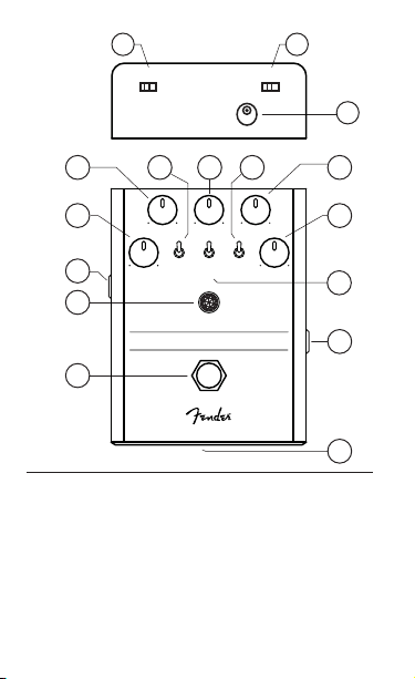
1. Footswitch
2. Jewel Indicator
3. Output Jack
4. Time
5. Depth
6. Type Switch
7. Rate
8. Variation Switch
DIGITAL
ON
1
ANALOG
2
OFF
TAPE
TYPE DOTTED
VARIATION
1/8
LEVEL
9. Feedback
10. Level
11. Dotted 1/8 Switch
12. Input Jack
13. Low Battery Indicator
14. LED Kill Switch
15. Dry Kill Switch
16. DC Power Connector
10
11
12
13

MIRROR IMAGE DELAY
Thank you for purchasing the Mirror Image
Delay—a versatile, easy-to-use and richly
featured digital delay. It delivers six high-quality
delay models—including tape, analog and
digital—plus three additional variations. It has
advanced features such as a Dry Kill switch for
use with amplifiers with parallel effects loops,
and a dotted-eighth function in which an
additional dotted-eighth-note delay can be
added to the main delay. The Mirror Image also
offers buffered bypass operation, in which the
footswitch allows delay tails to fade out naturally
when the pedal is turned off.
DESIGNED IN CALIFORNIA, U.S.A.

Time
This control adjusts delay time within the limits of the Delay Type
selected (each selection may vary—see “Algorithm Descriptions”
section). Lower settings produce short, metallic sounds akin to room
reverb, slapback delay and other small-dimension effects. Longer
echo settings are great for volume swells, ambient playing and
sound-on-sound experiments. Most fundamental sounds for lead and
rhythm playing—and for adding interesting rhythmic and spatial
effects—are toward the middle.
Note that there’s a delay “smear” as the Delay Time control knob is
turned. This is normal and is due to the delay time changing.
Level
This control adjusts how much delay is mixed with the dry signal. No
delay is present in the fully counterclockwise position. In the fully
clockwise position, the wet-dry mix is about 50/50. When Dry Kill is
active and this control is fully counterclockwise, no output is
produced. This is normal.
Feedback
This control adjusts the amount of delay fed back to the input from the
output, and it affects the number of repeats (this has sometimes been
called “regeneration” or “feedback”). The fully counterclockwise
position provides a single delay repeat (or two if the Dotted Eighth
switch is on); turning it up provides additional repeats.
Depth
This control works with the Rate control and provides pitch
modulation. Turning the Depth control fully counterclockwise turns the
modulation off, leaving an unaffected delay signal. Turning it fully
clockwise maxes out the pitch change. Note that the Rate and Depth
are coupled such that when Rate is set to maximum, Depth is reduced
to compensate; otherwise, there could be too much pitch shifting. To
add modulation, start with this control set at noon and adjust up or
down to preference. The “Doubler” (Digital Type, Variation 2) has a
different function for this knob—Delay Randomness

Rate
For most of the Delay Types, this control affects modulation speed.
Varying the delay time in this way can yield chorus, flange or
detuning effects that impart a wider spatial sound.
Dotted 1/8 Switch
The dotted-eighth note switch adds an additional delay signal in
which the new delay time is set to roughly 75 percent that of the main
delay. For example, if the Delay Time is set to half a second (500
milliseconds), one delay tap will sound after a half second while the
additional delay will sound at three-eighths of a second (0.75*500 =
375 milliseconds). This provides a dotted-eighth-plus-quarter note
rhythm, which is great for playing against quarter notes. This setting is
also useful for adding more dimension to short echoes, and it adds an
additional voice to the “Doubler” setting (Digital Type, Variation 2).
Type Switch
This switch selects Digital, Analog and Tape algorithms (see
“Algorithm Descriptions” section).
Variation Switch
This switch toggles between two variations for each reverb type
selection (see “Algorithm Descriptions” section).
Jewel Indicator
The Jewel Indicator shows when the delay is active.
Footswitch
The footswitch mutes the input to the delay engine. When turned off, it
lets delay tails fade out naturally.
Input Jack
This is a high-impedance input suitable for electric guitar, bass,
acoustic guitar with a pickup system, keyboards and other instruments.
Output Jack
This is a low-impedance output jack that connects to the amp or to the
next effect pedal in the signal chain.

DC Power Connector
This is a standard center-negative 9VDC jack for use with appropriate
power supplies.
Dry Kill Switch
The Dry Kill switch removes the original dry guitar signal from the
output, leaving only the wet delayed signal. With parallel effects
loops in a guitar amplifier, the idea is to always keep the original
guitar signal in the amp and use the effects loop only for the wet
signal. For normal use on a pedalboard, leave this switch off.
LED Kill Switch
This switch extinguishes the LEDs that illuminate the knobs—useful in
maximizing battery life when running the pedal from batteries.
Low Battery Indicator
This red LED on the front of the battery door illuminates when battery
voltage drops below a set threshold, indicating that the battery should
be replaced soon.

Algorithm Descriptions
Digital, Variation 1.
A straightforward digital delay with triangle wave modulation and no
filtering. The triangle wave produces a very smooth modulation that
almost sounds like detuning instead of chorus. Delay time range: 20
milliseconds to about 0.9 seconds.
Digital, Variation 2.
This is a “Doubler” algorithm—an automatic double-tracking effect. It
uses random timing and pitch variations to mimic the sound of multiple
guitar tracks. It also tracks playing and makes larger adjustments to
the timing and pitch between notes.
Use the Dotted Eighth switch to get one extra track (doubling when
combined with dry signal) or two extra tracks (tripling). Adjust the Mix
knob for the amount of doubling effect preferred; at 100 percent it
approximates the “tracks” being equal volume. Note that as Mix is
increased, sound may lose some focus.
Analog, Variation 1.
Emulates an old-school “bucket brigade” analog delay in all its lo-fi
glory—a little grit, a little noise and a lack of high end that all help this
effect sit back in the mix behind a dry guitar sound. The modulation
LFO is a sine wave.
Analog, Variation 2.
Like Variation 1, but worse (and by worse we mean better). There are
fewer highs and lows, there’s more grit, and the feedback is inverted
so the modulation can achieve credible flange sounds. Set Delay Time
low, set Feedback around 2 o’clock, and adjust Rate and Depth to
preference.

Tape, Variation 1.
A loving tribute to vintage tape echo units. Their quirks—like bad drive
motors, dirty tape heads, crinkled tape and rollers that are no longer
round—can give tape a slight pitch warble, a bit of hiss and noise,
and other kinds of distortion that can sound really good (like amp
distortion). There’s also tape-saturation emulation. To simulate
tape-like wow and flutter, this variation incorporates random
modulation. While random, its “speed” and depth can still be
adjusted with the Rate and Depth knobs.
Tape, Variation 2.
Like Tape, Variation 1, but with more warble, more saturation and
more bass and treble loss to mimic the sound of old tape.

FENDER MUSICAL INSTRUMENTS CORPORATION
A PRODUCT OF:
CORONA, CALIFORNIA, USA
Fender® is a registered trademark of FMIC.
Copyright © 2018 FMIC. All rights reserved.
P/N 7713290000 - REV A
Important Safety Instructions
•WARNING: To prevent damage, fire or shock hazard, do not expose the unit or its AC
power to rain or moisture.
•Do not alter the AC plug of the connected power adapter
•Do not drip or splash liquids on the unit.
•No user serviceable parts inside, refer servicing to qualified personnel only.
• WARNING: The unit must only be connected to a safety agency certified, regulated,
power source (adapter), approved for useand compliant with applicable local and
national regulatory safety requirements.
• Unplug the AC power adapter before cleaning the unit exterior. Use only a damp cloth
for cleaning and then wait until the unit is completely dry before reconnecting it to power.
• Amplifiers and loudspeaker systems, and ear/headphones (if equipped) are capable
of producing very high sound pressure levels which may cause temporary or permanent
hearing damage. Use care when setting and adjusting volume levels during use.
THIS DEVICE COMPLIES WITH PART 15 OF FCC RULES. OPERATION IS SUBJECT TO
THE FOLLOWING TWO CONDITIONS: (1) THIS DEVICE MAY NOT CAUSE HARMFUL
INTERFERENCE, AND (2) THIS DEVICE MUST ACCEPT ANY INTERFERENCE RECEIVED,
INCLUDING INTERFERENCE THAT MAY CAUSE UNDESIRED OPERATION.
Languages
Manual available in Espanol, francais, Italiano, Deutch, Portugues, (Chinese)
www.fender.com/support
Expanded Owner’s Manual
Expanded Owner’s Manual available at:
www.fender.com/support
Specifications
IMPEDANCES:
POWER SUPPLY:
POWER REQUIREMENTS:
DIMENSIONS:
WEIGHT:
Product specifications subject to change without notice
INPUT: 1MΩ OUTPUT LOAD: >10kΩ
One 9V battery or 9VDC regulated adapter,
5.5 x 2.1 mm barrel connector, center negative
72mA @ 9VDC
138mA, Total Current Consumption
3.75” x 4.9” x 2.5” (95.25mm x 124.5mm x 63.5mm)
1.2lbs (.54kg)

NOTES:

NOTES:

© FENDER MUSICAL INSTRUMENTS 2018
 Loading...