

OWNER’S/
OPERATOR’S
MANUAL
MODEL NO.’s
UB-645
UB-745
UB-650-T
UB-750-T
UB-850-T
CAUTION
For Safe Operation
Read Rules And
Instructions Carefully
SINO LEEINGLES, PIDAAYUDA
A AIGUIEN QUE SI LO LEA
PARA QUE LE TRADUZCA LAS
MEDIDAS DE SEGURIDAD.
CAUTION
THE FOLLOWING SAFETY PRECAUTIONS SHOULD BE THOROUGHLY UNDERSTOOD
BEFORE ATTEMPTING TO BEGIN ASSEMBLING THIS MACHINE
1. Select an area for assembly that is clean and free of any
debris which might cause persons working on the
assembly to trip.
2. Do not lift heavy parts or assemblies. Use crane, jack,
tackle, fork trucks or other mechanical devices.
3. Preview the assembly instructions in your operator’s
manual before proceeding further.
4. If the assembly instructions call for parts or assemblies to
be blocked up, use only blocking material that is in good
condition and is capable of handling the weight of the
assembly to be blocked. Also insure that the blocking
material is on a clean, dry surface.
5. Never put hands, or any part of body, under blocked up
assemblies if at all possible.
6. After completing assembly, thoroughly inspect the
machine to be sure that all nuts, bolts, hydraulic fittings
or any other fastened assemblies have been thoroughly
tightened.
7. Before operating the machine, thoroughly read the
operation section of your operator’s manual.
8. Before operating, read the maintenance section of your
operator’s manual to be sure that any parts requiring
lubrication, such as gearboxes, are full, to avoid any
possible damage.
9. Before operating equipment – If you have any
questions regarding the proper assembly or
operation, contact your dealer or representative.
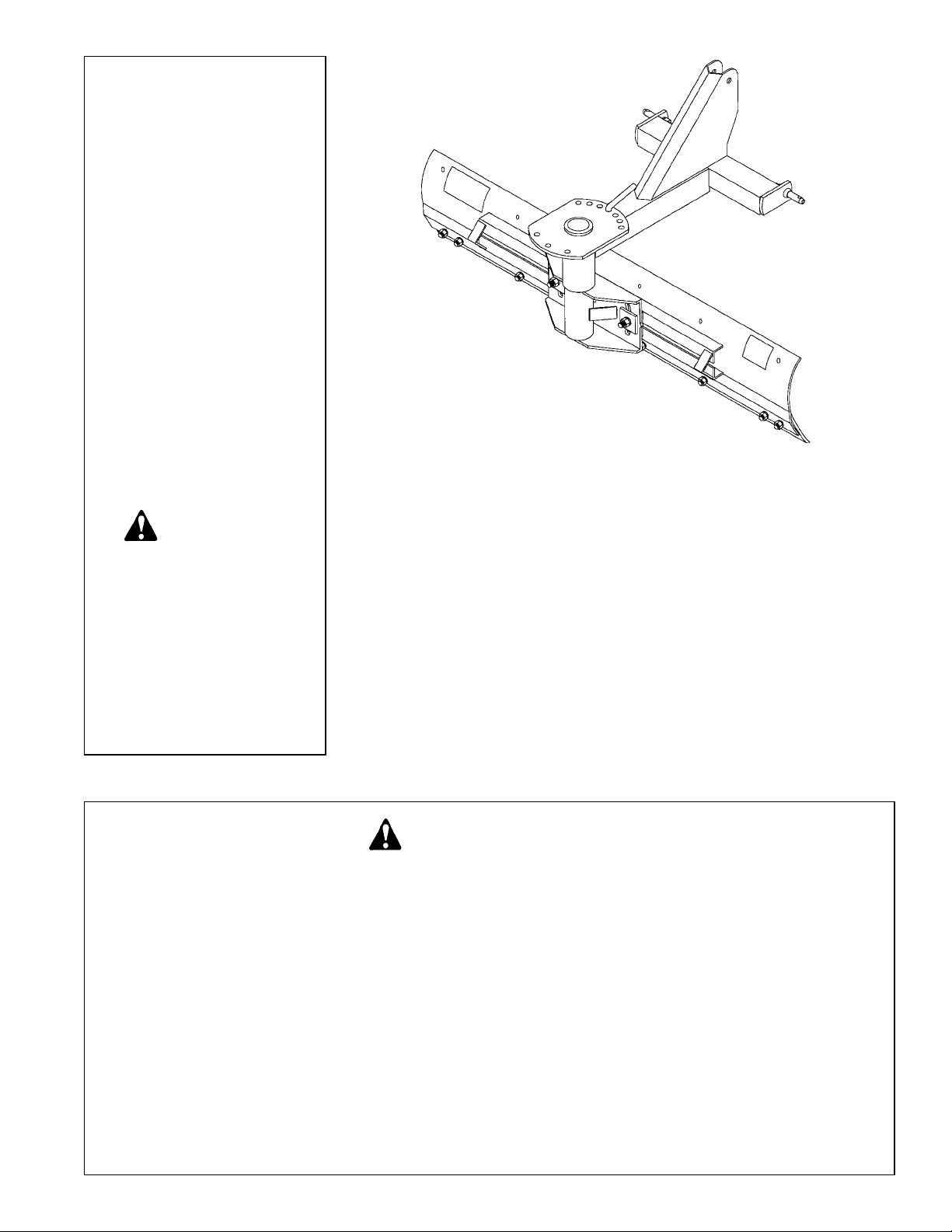
3 PT. REAR
MOUNTED BLADE
For Cat. I 3 Pt. Hitch Tractors
Up To 50 H.P.
Safety Instructions Assembly & Mounting
Tractor Preparation Maintenance
Operating Instructions Repair Parts

TABLE
OF
CONTENTS
SINO LEEINGLES, PIDA AYUDA A
AIGUIEN QUE SI LO LEA PARA QUE
LE TRADUZCA LAS MEDIDAS DE
SEGURIDAD.
SAFETY INFORMATION . . . . . . . . . . . . . . . . . . . . . . . . 2 - 4
STATEMENT
OF POLICY
SAFETY SIGNS . . . . . . . . . . . . . . . . . . . . . . . . . . . . . . 4
PREPARATION INSTRUCTIONS . . . . . . . . . . . . . . . . . 5
OPERATING INSTRUCTIONS . . . . . . . . . . . . . . . . . . . . 6
OWNER MAINTENANCE . . . . . . . . . . . . . . . . . . . . . . . 7
TROUBLESHOOTING GUIDE . . . . . . . . . . . . . . . . . . . . 8 - 9
PARTS DRAWING/LIST . . . . . . . . . . . . . . . . . . . . . . . . 10 - 13
It is the policy of Farm Star
to improve its products
where it is possible and practical
to do so. Farm Star
reserves the right to make
changes or improvements in
design and construction at any
time, without incurring the obligation to make these changes on
previously manufactured units.
TO THE OWNER:
Read this manual before using your 3 pt. Rear Blade. This manual is provided to give you the necessary
operating and maintenance instructions for keeping your Loader Fork in top operating condition. Please read this
manual thoroughly. Understand what each control is for and how to use it. Observe all safety signs on the
machine and noted throughout the manual for safe operation of implement. Keep this manual handy for ready
reference.
Like all mechanical products, it will require cleaning and upkeep.
Use only genuine Fa rm Star service parts. Substitute parts will void the warranty and may not meet stan-
dards required for safe and satisfactory operation. Record the model and serial number of your Rear Blade here:
Model:________________________________________ Serial Number:_______________________________
RETAIL CUSTOMER’S RESPONSIBILITY
It is the Retail Customer and/or Operator’s responsibility to read the Operator’s Manual, to operate, lubricate, maintain, and store the product in accordance with all instructions and safety procedures. Failure
of the operator to read the Operator’s Manual is a misuse of this equipment.
It is the Retail Customer and/or Operator’s responsibility to inspect the product and to have any part(s)
repaired or replaced when continued operation would cause damage or excessive wear to other parts or
cause a safety hazard.
It is the Retail Customer’s responsibility to deliver the product to the authorized Farm Star Dealer, from
whom he purchased it, for service or replacement of defective parts which are covered by warranty.
Repairs to be submitted for warranty consideration must be made within forty-five (45) days of failure.
It is the Retail Customer’s responsibility for any cost incurred by the Dealer for traveling to or hauling
of the product for the purpose of performing a warranty obligation or inspection.
1

2
T o the Owner/Operator/Dealer
All implements with moving parts are potentially hazardous. There is no substitute for a cautious, safe-minded operator who recognizes the potential hazards and follows reasonable safety practices. The manufacturer has designed this
implement to be used with all its safety equipment properly attached to minimize the chance of accidents.
BEFORE YOU START!!
Read the safety messages on the implement and shown in your manual.
Observe the rules of safety and common sense!
THIS SAFETY ALERT SYMBOL IDENTIFIES IMPORTANT
SAFETY WARNING MESSAGES. CAREFULL YREAD EACH
WARNING MESSAGE THAT FOLLOWS. FAILURE TO
UNDERSTAND AND OBEY A SAFETY WARNING, OR
RECOGNIZE A SAFETY HAZARD, COULD RESULT IN AN
INJURY OR DEATH TO YOU OR OTHERS AROUND YOU.
THE OPERATOR IS ULTIMATELY RESPONSIBLE FOR THE
SAFETY OF HIMSELF, AS WELL AS OTHERS, IN THE
OPERATING AREA OF THE TRACTOR AND ATTACHED
EQUIPMENT.
IMPORTANT SAFETY INFORMATION!
Working with unfamiliar equipment can lead to careless injuries. Read this manual, and the manual for your tractor,
before assembly or operating, to acquaint yourself with the machines. It is the implement owner’s responsibility, if this
machine is used by any person other than yourself, is loaned or rented, to make certain that the operator, prior to
operating:
1. Reads and understands the operator’s manuals.
2. Is instructed in safe and proper use.
The use of this equipment is subject to certain hazards which cannot be protected against by mechanical
means or product design. All operators of this equipment must read and understand this entire manual, paying
particular attention to safety and operating instructions, prior to using. If there is something in this manual you
do not understand, ask your supervisor, or your dealer, to explain it to you.
THIS SYMBOL MEANS
– A TTENTION!
– BECOME ALERT!
– YOUR SAFETY IS INVOLVED!
UNDERSTAND SIGNAL WORDS
Note the use of the signal words DANGER, WARNING
and CAUTION with the safety messages. The
appropriate signal word for each has been selected
using the following guidelines:
DANGER: Indicates an imminently hazardous situation
that, if not avoided, will result in death or serious injury.
This signal word is to be limited to the most extreme
situations typically for machine components which, for
functional purposes, cannot be guarded.
If you have questions not answered in this manual or require additional copies or the manual is damaged, please
contact your dealer or the manufacturer directly.
WARNING: Indicates a potentially hazardous situation that, if not avoided, could result in death
or serious injury, and includes hazards that are
exposed when guards are removed. It may also
be used to alert against unsafe practices.
CAUTION: Indicates a potentially hazardous situation that, if not avoided, may result in minor or
moderate injury. It may also be used to alert
against unsafe practices.

SAFETY INSTRUCTIONS (continued)
All equipment is potentially hazardous. There is no substitute for a cautious, safe-minded operator who
recognizes potential hazards and follows reasonable safety practices.
When the use of hand tools is required to perform any part of assembly, installation, adjustment, maintaining,
repairing, removal, or moving the implement, be sure the tools used are designed and recommended by the
tool manufacturer for that specific task.
Personal protection equipment including safety glasses, safety shoes, and gloves are recommended during
assembly, installation, operation, adjustment, maintaining, repairing, removal, or moving the rear blade.
Always use two people to handle heavy, unwieldy components during assembly, installation, removal, or
moving the rear blade.
Never place any part of your body where it would be in danger if movement should occur during assembly,
installation, operation, maintaining, repairing, removal, or moving the implement.
Never place yourself between the tractor and implement while implement is in operation.
Do not work under a raised implement unless it is securely blocked or held in position. Do not depend on the
tractor hydraulic system to hold the implement in place.
A heavy load can cause instability of the tractor. Use extreme care during travel. Slow down on turns and
watch out for bumps. The tractor may need front counter-weights to counter-balance the weight of the
implement.
Never use alcoholic beverages or drugs which can hinder alertness or coordination while operating this
equipment. Consult your doctor about operating this machine while taking prescription medications.
Do not allow others to ride on the tractor with an operator. Riders are subject to injury such as being struck by
foreign objects or being thrown off. Riders obstruct the operator’s view resulting in unsafe operation. Never
allow anyone to ride on the implement!
Before you operate the rear blade, check over all pins, bolts and connections to be sure all are securely in
place. Replace any damaged or worn parts immediately.
Do not allow anyone who is not familiar with the safety rules and operation instructions to use this rear blade.
Never allow children to operate or be around equipment.
Use stabilizer bars, adjustable sway chains, or sway blocks on your tractor lift arms to keep the rear blade from
swinging side to side. Adjust as tightly as practical for best performance.
3

4
SAFETY INSTRUCTIONS (continued)
SAFETY SIGNS
This SAFETY SIGN is
located on the frame of
your rear blade.
Obey ALL Safety
Warnings.
NOTE:
If Safety Sign is missing
or damaged, replace
immediately.
Keep alert and watch the front as well as the rear when working with the implement.
When maneuvering close to buildings or passing through narrow areas, be sure to allow sufficient clearance
for the implement.
Do not operate close to ditches or creeks. Slow down when operating over rough ground.
Always be sure the implement is in the fully raised position when in transport.
When adjusting the angle of the moldboard assembly, be sure that your feet are never under the rear blade.
Use extreme caution when backfilling deep holes or trenches.
Be careful to avoid catching the rear blade on stumps or other immovable objects.
Use care when working on slopes.
Avoid excessive speed during operation.
Make adjustments only when the implement is attached to the tractor.
When using the rear blade in a reverse position, use extra care. Do not ram rear blade into piles of dirt.
Tractor lift arms and the rear blade are not built to take high impact loads in this position. Ramming backwards
can also dislodge operator from seat and/or tractor controls, resulting in possible serious injury or death.
Always ease the tractor into the load. It may be necessary to reposition and take less “bite” on the material to
move it safely.
Watch for and avoid hidden obstructions, i.e., buried pipes, rocks, concrete piers, uneven concrete slabs,
stumps, etc., when operating.

INSTRUCTIONS
TRACTOR REQUIREMENTS
AND PREPA R ATION
The UB Series Rear Blades will fit most Category I
tractors equipped with a standard 3-point hitch. These
blades are designed for use on tractors up to 50
horsepower. For use on larger tractors, extra care is
required and it is strongly suggested that purchasing a
heavier rear blade be considered.
Check the tractor’s 3-point hydraulic lift system. It
should operate up and down smoothly and hold its
position when set. Refer to your tractor owner’s manual
or dealer for any adjustments necessary to put the 3point hydraulic lift system in good working order. (I&T
shop manuals will list most specifications and adjustment
instructions – available from most farm equipment
dealers.)
Tractor should be equipped with stabilizer bars,
adjustable sway chains, or sway blocks to keep the
implement from swinging side to side.
Smaller size tractors may need front counter weights to
counter-balance the weight of the implement.
It is recommended that the tractor be equipped with a
Rollover Protection System (ROPS) and a seat belt that
is used.
CAUTION!
Be sure your tractor is in good condition and
properly equipped with counter weights. Read all the
safety precautions and make sure all tractor
operators are familiar with the safety rules of tractor
operation.
UB-645 BLADE
(6 ft. Moldboard mounting instruction.)
1. Remove the two center plow bolts from the moldboard
assembly.
2. Position the moldboard assembly in front of the spindle assembly and place the two center plow bolts
through the moldboard assembly and into the corresponding holes in the lower moldboard bracket on the
spindle assembly.
3. Place the two 1/2” x 11/2” hex head bolts provided
through the two center holes at the top of the
moldboard assembly into the corresponding holes on
the upper moldboard bracket on the spindle assembly .
(NOTE: The moldboard assembly may be positioned
in the center, 12” to the right, or 12” to the left, according to the setting desired.)
4. Tighten all bolts securely.
UB-745 BLADE
(7 ft. Moldboard mounting instruction.)
1. Remove the three center plow bolts from the moldboard assembly.
2. Position the moldboard assembly in front of the spindle assembly and place the three center plow bolts
through the moldboard assembly and into the corresponding holes in the lower moldboard bracket on the
spindle assembly.
3. Place the two 1/2” x 11/2” hex head bolts provided
through the two center holes at the top of the moldboard
assembly and into the corresponding holes on the
upper moldboard bracket on the spindle assembly.
(NOTE: The moldboard assembly may be positioned
in the center, 12” to the right, or 12” to the left, according to the setting desired.)
4. Tighten all bolts securely.
ASSEMBLY AND MOUNTING
It is suggested that you mount the main frame on the 3point hitch of your tractor before assembling the blade as
follows:
1. Lower the 3-point hitch on your tractor to facilitate
mounting of the main frame of the blade to the tractor.
2. Insert the lift arm pins on the main frame into the ball
sockets in the lift arms of the tractor 3-point hitch. Pin
in place with linch pins (not furnished).
3. Attach the mast of the main frame to the tractor by
installing the tractor center (or top) link with a top link
pin (not furnished). Pin in place with a linch pin (not
furnished).
The main frame of the blade is now installed on the
tractor. You are ready to proceed with assembling the
moldboard and cutting edge assembly to the main frame
as follows:
UB-650-T, UB-750-T, AND UB-850-T BLADES
(6 ft., 7 ft., & 8 ft. Moldboard mounting instructions.)
1. Place the two tilt adjustment bolts into the moldboard
brackets (one on each end).
2. Position the moldboard against the spindle mounting
bracket, with the two tilt adjustment bolts extending
through the radial slots in the spindle mounting bracket.
3. Place the tie plates over the tilt adjustment bolts.
4. Tighten all bolts securely.
5. In order to tilt the moldboard simply loosen the nuts
on the tilt adjustment bolts and pivot to the desired
angle, then retighten the nuts.
NOTE:Always use the tractor anti-sway bars, blocks, or
chains to prevent blade side-sway. This is a must when
using the blade in a reverse position.
Your Rear Mounted Blade is now assembled and
mounted on your tractor. It is ready to go to work for you.
5

6
INSTRUCTIONS (continued)
When using the rear blade in a reverse position use
extra care - DO NOT RAM REAR BLADE into dirt
piles! Tractor lift arms and the rear blade are not
built to take high impact loads in this position. RAMMING backwards can also dislodge operator from
seat and/or tractor controls, resulting in possible
serious injury or death.
CAUTION!
Watch for and avoid hidden obstructions, i.e.,
buried pipes, rocks, concrete piers, or uneven slabs
of concrete, when operating, or blade damage may
occur. This is especially true when removing snow.
CAUTION!
O PE R ATION
Check for ditches, stumps, holes, or other obstacles
that could upset tractor or damage blade. Always turn off
tractor engine, set parking brake, lower blade to ground
before dismounting tractor.
Attaching the blade to the tractor increases the overall
length of the working unit. Allow additional clearance for
the blade to swing when turning.
Your rear blade can be used for all types of blade
work, including casting, side ditching, leveling, terracing,
grading, bulldozing, and snow removal.
1. CASTING: The blade should be angled horizontally –
only enough to allow the material to slide along it
easily . The vertical angle (tilt) of the blade must be set
to suit conditions. This is controlled by the lift arm
leveling assembly (turnbuckle) on the tractor 3-point
hitch.
2. SIDE DITCHING: The horizontal angle should be at
its sharpest. This is obtained by removing the shift pin
and turning the moldboard so that the last hole in the
circle plate is in line with the shift pin hole, then
replace the shift pin. It is suggested that the blade be
set in an offset position and then use the shorter
blade side to be the cutting side. This reduces the
load movement on the end of the blade.
The vertical angle of the blade (tilt) is adjusted by
means of the adjustable turnbuckles on the tractor 3point hitch. For the sharpest angle, lengthen the
center link on the tractor as far as possible. Also,
lower the adjustable leveling turnbuckle as far as
possible.
3. LEVELING: The blade should be straight across, i.e.,
90˚ to the line of travel of the tractor, in other words 0˚
horizontal angle.
There should be 0˚ vertical angle, i.e., the lift arms
on the tractor 3-point hitch should be parallel to the
ground.
The cutting pitch of the blade should be the opposite of that used in side ditching and casting, with the
cutting edge behind the top edge of the moldboard.
This adjustment is made with tractor center link.
4. TERRACING: Use a combination of ditching, casting,
and leveling. The first cut is into the hillside in the
ditching position. Continue until the terrace is at
proper depth, then switch to the casting position until
the terrace width is established. It may be necessary
to use the leveling position to complete the job.
5. BULLDOZING: When bulldozing, the blade is in
reverse position. Depending on the job, the casting,
side ditching, or leveling position may be used. Snow
removal can also be done with the blade in this
position (blade in reverse, cutting edge away from
tractor).
(NOTE: Most blades are damaged in this position –
use extra care – DO NOT RAM blade into snow or
dirt piles!)
6. GRADING: Grading is a combination of casting, side
ditching, and leveling. Snow removal can also be
done with the blade in this position (cutting edge
toward the tractor).
These suggestions are generalities; best results will be
obtained after some experience.
NOTE: Do not load either end of the blade heavily. Try
to balance the load on both ends of the blade.
GENERAL SAFETY
The designed and tested safety of this machine
depends on it being operated within the limitations as
explained in this manual. Be familiar with and follow all
safety rules in the manual, on the blade and on the
tractor.
The safe operation of this machine is the responsibility
of the owner / operator. The operator should be familiar
with the blade and tractor and all safety practices before
starting operation. Read the safety rules.
Never let anyone stand between the rear of the tractor
and the rear blade while the tractor is backing up to connect to the blade. Always stand to the side until tractor
has come to a complete stop and the brakes set or the
tractor shift placed in “PARK”.

OWNER SERVICE
TRANSPORTING
Pay particular close attention to the Safety Messages
regarding transport. Avoid unnecessary injuries and
equipment damage by exercising cautious, conscientious travel procedures.
Attaching the blade to the tractor increases the overall
length of the working unit. Allow additional clearance for
the blade to swing when turning.
Raise the blade as high as possible for transporting.
Always transport blade with blade centered on tractor.
Never attempt road travel with blade offset into the traffic
lane.
MAINTENANCE
W ARNING!
▲ Lower blade to ground or block securely, turn trac-
tor engine off, remove key and set brakes or place
shift lever in “Park” position.
▲ Before working underneath, raise 3-pt. hitch to
highest position and block blade securely.
Hydraulic system leakdown and failure of
mechanical or hydraulic system can cause equipment to drop.
STORING SAFELY
• Never store equipment with fuel in the tank inside a
building where fumes may reach an open flame or
spark. Allow engine to cool before storing in an
enclosure.
• Always store blade in a clean, dry location away from
children or livestock.
• Storage location should be level and solid to make
hitching and unhitching easy.
OPTIONS
The optional skid shoes provide cutting height adjustment to reduce the chance of blade or surface damage
during snow removal. This option is very helpful when
plowing gravel or loose stone driveways.
OPTIONAL
MODEL SK-6 SKID SHOE INSTALLATION
Attach the skid shoe mounting bracket to the 2nd and
3rd cutting edge holes from each end of the moldboard.
Insert the skid shoe in the mounting bracket and secure
with the 1/2” – 13NC x 11/2” long square head set screw
and jam nut. Be sure the skid shoes are turned so the
adjustment holes match the point of the set screw. See
parts illustration.
▲ Keep all persons away from operator control area
while performing adjustments, service or maintenance.
▲ Do not run engine indoors – exhaust gases
contain carbon monoxide, an odorless and deadly
poison.
Inspect the blade for loose, damaged or worn parts and
adjust or replace if needed.
Repaint parts where paint is worn or scratched to
prevent rust.
Check all bolts and nuts to be sure they are tight.
At the end of the working season or when the blade will
not be used for a long period, it is good practice to clean
off any dirt that may have accumulated on the blade and
any of the moving parts.
Check the shift pin for excessive wear and replace if
necessary.
Always store blade in a clean, dry location away from
children or livestock.
Optional end plates provide a “boxed” blade for grading. This is helpful when spreading dirt or loose stone or
just leveling an area. It keeps the material from sliding off
the end of the blade.
OPTIONAL
MODEL EP-38 END PLATE INSTALLATION
The end plates mount to the inside of the blade using
the end cutting edge hole and the hole in the moldboard
directly above it. Replace the cutting edge bolt with the
longer 5/8” – 11NC x 2” long carriage bolt provided. On
earlier models it may be necessary to match drill the
upper 11/16” Dia. hole in the moldboard. Install the upper
5
/8” – 11NC carriage bolt. See parts illustration.
OBEY ALL
SAFETY WARNINGS!
7

8
TROUBLESHOOTING GUIDE
PROBLEM POSSIBLE CAUSE POSSIBLE REMEDY
Blade will not penetrate
soil.
1. Cutting edge dull.
2. Blade set too straight.
3. Soil too hard.
Replace cutting edge.
Increase 3 pt. hitch toplink length.
Loosen soil with scarifiers or disk.
Wait for rain.
Moldboard digging in
too much.
1. Blade pitch excessive.
2. Soft ground.
Adjust toplink (shorten).
Install skid shoes.
Wait for dryer soil.
3 Pt. hitch frame bent.
1. Hitting hidden objects in backfill
position or ramming backwards at
high speed into hard piles.
2. Using too large of tractor.
Use slow speed when in unknown
conditions.
Always backfill or push backwards
at slow speed.
Preferably use tractor of recommended horsepower.
Slow down and use extra care.
Unable to hold level
grade.
1. Tractor draft control lifting blade.
2. Soil too hard.
Set tractor draft control.
Use scarifiers.
Bent moldboard.
1. Small curve is normal from welding.
2. Hitting hidden objects in backfill
position or ramming backwards at
high speed into hard piles of soil,
snow, or ice.
3. Using too large of tractor or one that
is heavily weighted and has four
wheel drive.
Can be removed, but will not effect
blade operation.
Use slow speed when in unknown
conditions.
Always backfill or push backwards
at slow speed.
Preferably use tractor of recommended horsepower.
Slow down and use extra care.

TROUBLESHOOTING GUIDE
PROBLEM POSSIBLE CAUSE POSSIBLE REMEDY
Only one end of blade
moldboard cutting or
“working.”
Blade moves side to
side.
Front of tractor moves
sideways when blade is
angled.
1. Moldboard not level. Adjust tractor 3 pt. linkage to level
lift arms.
1. Anti-sway bars, blocks, or chains
missing.
2. Anti-sway chains loose.
1. Too much material being handled.
2. Tractor too light.
Install anti-sway bars, blocks or
chains.
Adjust chains.
Reduce material load.
Add front weights.
Use larger size tractor.
Angle shift pin breaks
or bends.
Blade catches
cracks/joints in hard
surface driveways.
Blade plows most loose
stone/gravel into grass
at side of driveway.
1. Hitting solid objects.
2. Ramming blade into “solid” snow/ice
or dirt piles.
3. Using too large tractor.
Drive carefully and check work
area.
Stop dangerous practice.
Use proper size tractor for blade
rating.
PLOWING SNOW PROBLEMS:
1. Need optional skid shoes. Add skid shoes.
1. Skid shoes not adjusted properly. Adjust skid shoes so cutting edge
clears.
9

10
REF. PART NO.
NO. NO. DESCRIPTION REQ.
1 346601 3 Pt. Mount Frame 1
2 590108 Lift Pin Assembly (AK-578) 2
3 350030 Adjustment Pin 1
4 2500003 Full Hex Nut 1/2” – 13NC 2
5 2502002 Spring Lockwasher 1/2”2
6 2500013 Full Hex Nut 5/8” – 11NC 8
7 2502007 Spring Lockwasher 5/8”8
8 2503045 No. 3 Plow Head Bolt 5/8” – 11NC x 11/2”6
9 2503179 No. 3 Plow Head Bolt 5/8” – 11NC x 2” 2
10 350405 6 Ft. Cutting Edge 1
11 346612 6 Ft. Moldboard 1
12 2503004 Hex Head Bolt 1/2” – 13NC x 11/2”2
13 101033 Decal – Caution, Safe Operating Practices 1
14 101052 Decal – Warranty Notice 1
UB-645 BLADE
REF. PART NO.
NO. NO. DESCRIPTION REQ.
1 346601 3 Pt. Mount Frame 1
2 590108 Lift Pin Assembly (AK-578) 2
3 350030 Adjustment Pin 1
4 2500003 Full Hex Nut 1/2” – 13NC 2
5 2502002 Spring Lockwasher 1/2”2
6 2500013 Full Hex Nut 5/8” – 11NC 9
7 2502007 Spring Lockwasher 5/8”9
8 2503045 No. 3 Plow Head Bolt 5/8” – 11NC x 11/2”6
9 2503179 No. 3 Plow Head Bolt 5/8” – 11NC x 2” 3
N/S 350029 7 Ft. Cutting Edge 1
N/S 346701 7 Ft. Moldboard 1
12 2503004 Hex Head Bolt 1/2” – 13NC x 11/2”2
13 101033 Decal – Caution, Safe Operating Practices 1
14 101053 Decal – Warranty Notice 1
UB-745 BLADE
MODEL NO.
UB-645
SHOWN

MODEL NO.
UB-650-T
SHOWN
UB-650-T
UTILITY BLADE
REF. PART NO.
NO. NO. DESCRIPTION REQ.
1 346801 Mount Frame 1
2 346807 Moldboard Assembly 1
3 350405 Cutting Edge 1
4 2503045 Plow Bolt 5/8” – 11NC x 11/2”8
5 2502007 Lockwasher 5/8”8
6 2500013 Nut 5/8” – 11NC Full Hex 8
7 346810 Tilt Adjustment Bolt 2
8 346812 Tie Plate 2
9 2502001 Lockwasher 3/4”2
10 2500002 Nut 3/4” – 10NC Full Hex 2
11 590108 Lift Pin (AK-578) 2
12 350030 Adjustment Pin 1
13 101033 Decal – Caution, Safe Operating Practices 1
14 101054 Decal – Warranty Notice 1
11

12
REF. PART NO.
NO. NO. DESCRIPTION REQ.
1 346801 Mount Frame 1
N/S 346901 Moldboard Assembly 1
N/S 350029 Cutting Edge 1
4 2503045 Plow Bolt 5/8” – 11NC x 11/2”9
5 2502007 Lockwasher 5/8”9
6 2500013 Nut 5/8” – 11NC Full Hex 9
7 346810 Tilt Adjustment Bolt 2
8 346812 Tie Plate 2
9 2502001 Lockwasher 3/4”2
10 2500002 Nut 3/4” – 10NC Full Hex 2
11 590108 Lift Pin (AK-578) 2
12 350030 Adjustment Pin 1
13 101033 Decal – Caution, Safe Operating Practices 1
14 101055 Decal – Warranty Notice 1
UB-750-T
UTILITY BLADE
REF. PART NO.
NO. NO. DESCRIPTION REQ.
1 346801 Mount Frame 1
N/S 347001 Moldboard Assembly 1
N/S 350105 Cutting Edge 1
4 2503045 Plow Bolt 5/8” – 11NC x 11/2”10
5 2502007 Lockwasher 5/8”10
6 2500013 Nut 5/8” – 11NC Full Hex 10
7 346810 Tilt Adjustment Bolt 2
8 346812 Tie Plate 2
9 2502001 Lockwasher 3/4”2
10 2500002 Nut 3/4” – 10NC Full Hex 2
11 590108 Lift Pin (AK-578) 2
12 350030 Adjustment Pin 1
13 101033 Decal – Caution, Safe Operating Practices 1
14 101142 Decal – Warranty Notice 1
UB-850-T
UTILITY BLADE

SK-6 (OPTIONAL)
REF. PART NO.
NO. NO. DESCRIPTION REQ.
1 346632 Skid Shoe Weldment 2
2 346635 Mount Weldment 2
3 2503203 Set Screw 1/2” – 13NC x 11/2” Sq. Head 2
4 2500058 Nut 1/2” – 13NC Hex Jam 2
5 2504068 Cotter Pin 1/4” x 13/4”2
N/S 2503179 No. 3 Plow Head Bolt 5/8” – 11NC x 2” 4
EP-38 (OPTIONAL)
REF. PART NO.
NO. NO. DESCRIPTION REQ.
1 346621 End Plate 2
2 2503136 Bolt 5/8” – 11NC x 2” Carriage Head Grade 5 4
3 2502007 Washer 5/8” Springlock 4
4 2500013 Nut 5/8” – 11NC Full Hex 4
13

14
LIMITED WARRANTY
Farm Star warrants its implements, parts and accessories to be free from defects in materials and workmanship for a period of six (6) months from date of purchase for non-commercial, state, and municipalities’. Use
ninety (90) days for commercial use from date of retail sale.
SPECIAL WARRANTY PROVISION
Warranty shall only apply to defects in material and workmanship. In no case shall the manufacturer be liable
to the purchaser for the bending or breakage of any part of the blade by abuse or misuse, such as striking
hidden objects, grubbing stumps, or using tractors larger than the blades maximum horsepower rating whether
intentional or unintentional.
DISCLAIMER OF IMPLIED WARRANTIES & CONSEQUENTIAL DAMAGES
Farm Star’s obligation under this warranty, to the extent allowed by law, is in lieu of all warranties, implied or
expressed, including implied warranties of merchantability and fitness for a particular purpose and any liability
for incidental and consequential damages with respect to the sale or use of the items warranted. Such
incidental and consequential damages shall include but not be limited to: transportation charges other than
normal freight charges; cost of installation other than cost approved by Farm Star; duty; taxes; charges for
normal service or adjustments; loss of crops or any other loss of income; rental of substitute equipment,
expenses due to loss, damage, detention or delay in the delivery of equipment or parts resulting from acts
beyond the control of Farm Star.
THIS WARRANTY SHALL NOT APPLY:
1. If the unit has been subjected to misapplication, abuse, misuse, negligence, fire or other accident.
2. If parts not made or supplied by Farm Star have been used in connection with the unit, if, in sole
judgement of Farm Star such use affects its performance, stability, or reliability.
3. If the unit has been altered or repaired outside of an authorized Farm Star dealership in a manner which,
in the sole judgement of Farm Star affects its performance, stability or reliability.
4. To expendable or wear items such as skid shoes, cutting edges, and other items that in the company’s sole
judgement is a wear item.
NO EMPLOYEE OR REPRESENTATIVE OF FARM STAR IS AUTHORIZED TO CHANGE THIS
WARRANTY IN ANY WAY OR GRANT ANY OTHER WARRANTY UNLESS SUCH CHANGE IS MADE IN
WRITING AND SIGNED BY FARM STAR’S SERVICE MANAGER, POST OFFICE BOX 100, LITCHFIELD,
ILLINOIS 62056-0100.

SAFETY PRECAUTIONS
MOST ACCIDENTS OCCUR BECAUSE OF NEGLECT OR CARELESSNESS.
AVOID NEEDLESS ACCIDENTS BY FOLLOWING ALL OF THE SAFETY PRECAUTIONS LISTED BELOW.
• Machinery should be operated only by those who are
responsible and are authorized to do so.
• Stop the engine, lower all equipment, lock the brakes,
and remove the ignition key before dismounting from the
tractor.
• Never stand between tractor and implement while tractor
is being backed to hitch.
• Loose fitting clothing should not be worn, to avoid catch-
ing on various parts.
• Detach implement in area where children normally do not
play.
• When performing adjustments or maintenance on an
implement, first lower it to the ground or block it securely
at a workable height.
• Only a qualified operator should be permitted on tractor
when in operation; no riders allowed.
• Make certain everyone is in the clear before starting
tractor or raising or lowering equipment.
• Operate the tractor and implement only while seated in
the driver’s seat.
•
Reduce speed when transporting mounted implements
to avoid bouncing and momentary loss of steering
control.
• A heavy load can cause instability of the tractor. Use
extreme care during road travel. Slow down on turns and
watch out for bumps. Tractor may need front counterweights to counter-balance the weight of the implement.
• Reduce speed on hillsides or curves so there is no
danger of tipping.
• Avoid driving too close to the edge of ditches or creeks.
• Do not transport implement on public roads without
reflectors and slow moving vehicle emblem in daylight
and with approved warning lights at night and other
periods of poor visibility.
• Due to the width of some implements, use extra caution
on highways, farm roads, and when approaching gates.
• Always be sure the implement is in the proper position for
transport.
• Keep alert and watch the front as well as the rear when
working with the implement.
OWNER’S/
OPERATOR’S
MANUAL
MODEL NO.’s
UB-645
UB-745
UB-650-T
UB-750-T
UB-850-T
3 PT. REAR MOUNTED BLADE
For Cat. I 3 Pt. Hitch Tractors
up to 50 H.P.
WHEN ORDERING REPAIR PARTS,
ALWAYS GIVE THE
FOLLOWING INFORMATION:
1. PART NUMBER
2. PART DESCRIPTION
3. MODEL NUMBER
4. NAME OF ITEM
MAKE EVERY DAY
A HOLIDAY
FROM ACCIDENTS!
JANUARY 2002
FS-RB002-OG
FARM STAR
P.O. BOX 100 LITCHFIELD, IL 62056-0100 (217) 324-5973
WEB: http:// www.farmstar.com E-MAIL: sales@farmstar.com
 Loading...