

Page 1
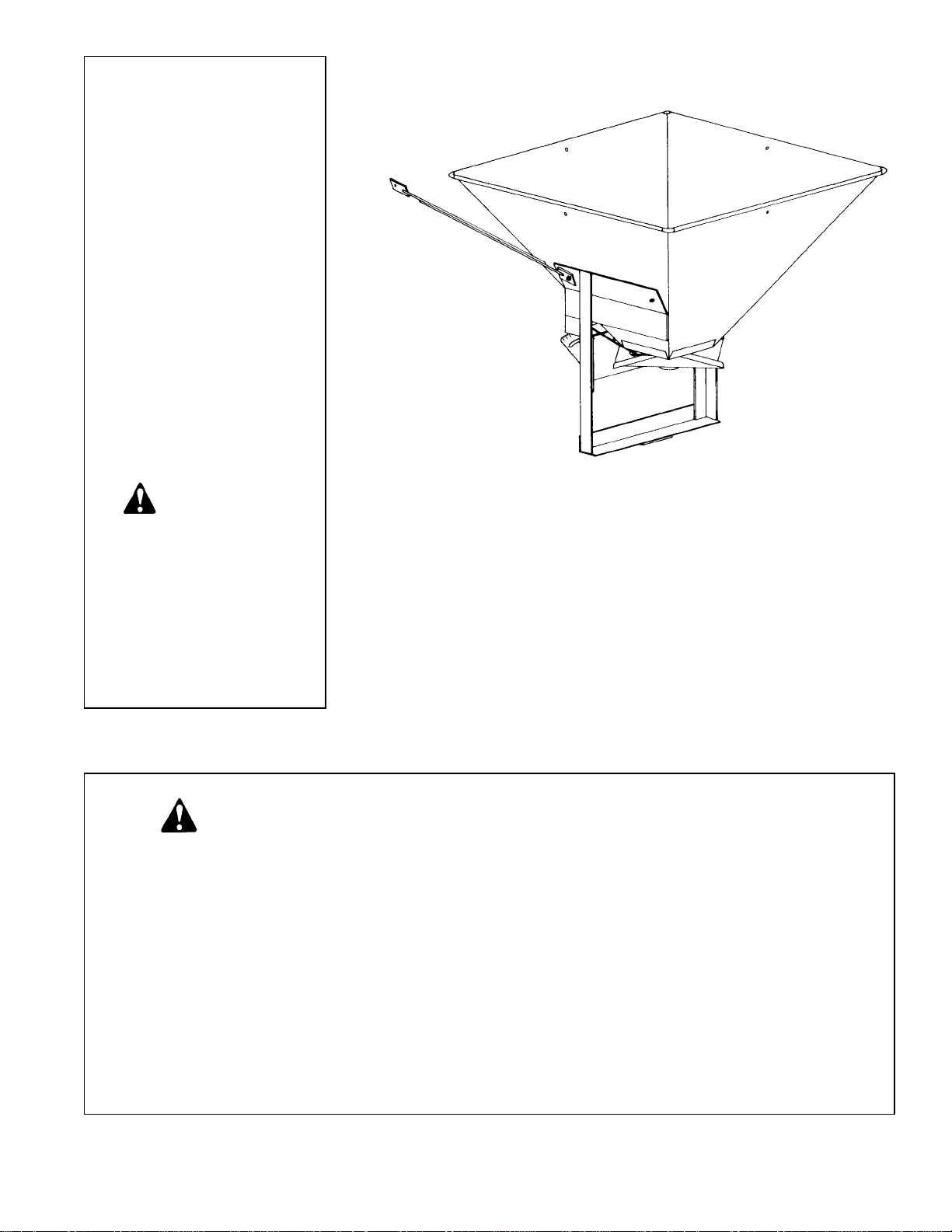
ELECTRIC SEEDER
OWNER’S/
OPERATOR’S
MANUAL
MODEL NO.’s
ES-1.5
ES-1.5 PKP
ES-33
CAUTION
For Safe Operation
Read Rules And
Instructions Carefully
SINO LEEINGLES, PIDAA YUDA
A AIGUIEN QUE SI LO LEA
PARA QUE LE TRADUZCA LAS
MEDIDAS DE SEGURIDAD.
Safety Instructions Assembly & Mounting
Tractor Preparation Maintenance
Operating Instructions Repair Parts
ATTENTION! SAFETY RULES
1.Read instruction manual and make sure all operators are knowledgeable on
correct operation of equipment and familiar with the Safety Rules of Operation.
2.Never allow riders on equipment.
3. When operating on rough or uneven terrain, use extreme caution and a safe
operating speed.
4.When spreading seed or fertilizer, always use safety goggles.
5.Never operate equipment when anyone is within 50 feet of seeder/spreader.
Before operating equipment – If you have any questions regarding the proper assembly or
operation, contact your dealer or representative.
Page 2
T o the Owner/Operator/Dealer
All implements with moving parts are potentially hazardous. There is no substitute for a cautious, safe-minded operator who recognizes the potential hazards and follows reasonable safety practices. The manufacturer has designed this
implement to be used with all its safety equipment properly attached to minimize the chance of accidents.
BEFORE YOU START!!
Read the safety messages on the implement and shown in your manual.
Observe the rules of safety and common sense!
THIS SAFETY ALERT SYMBOL IDENTIFIES IMPORTANT
SAFETY WARNING MESSAGES. CAREFULLYREAD EACH
WARNING MESSAGE THAT FOLLOWS. FAILURE TO
UNDERSTAND AND OBEY A SAFETY WARNING, OR
THIS SYMBOL MEANS
– A TTENTION!
– BECOME ALERT!
– YOUR SAFETY IS INVOLVED!
RECOGNIZE A SAFETY HAZARD, COULD RESULT IN AN
INJURY OR DEATH TO YOU OR OTHERS AROUND YOU.
THE OPERATOR IS ULTIMATELY RESPONSIBLE FOR THE
SAFETY OF HIMSELF, AS WELL AS OTHERS, IN THE
OPERATING AREA OF THE TRACTOR AND EQUIPMENT.
UNDERSTAND SIGNAL WORDS
Note the use of the signal words DANGER, WARNING
and CAUTION with the safety messages. The
appropriate signal word for each has been selected
using the following guidelines:
DANGER: Indicates an imminently hazardous situation
that, if not avoided, will result in death or serious injury.
This signal word is to be limited to the most extreme
situations typically for machine components which, for
functional purposes, cannot be guarded.
WARNING: Indicates a potentially hazardous situation that, if not avoided, could result in death
or serious injury, and includes hazards that are
exposed when guards are removed. It may also
be used to alert against unsafe practices.
CAUTION: Indicates a potentially hazardous situation that, if not avoided, may result in minor or
moderate injury. It may also be used to alert
against unsafe practices.
IMPORTANT SAFETY INFORMATION!
Working with unfamiliar equipment can lead to careless injuries. Read this manual, and the manual for your tractor,
before assembly or operating, to acquaint yourself with the machine. It is the equipment owner’s responsibility, if this
equipment is used by any person other than yourself, is loaned or rented, to make certain that the operator, prior to
operating:
1. Reads and understands the operator’s manuals.
2. Is instructed in safe and proper use.
The use of this equipment is subject to certain hazards which cannot be protected against by mechanical
means or product design. All operators of this equipment must read and understand this entire manual, paying
particular attention to safety and operating instructions, prior to using. If there is something in this manual you
do not understand, ask your supervisor, or your dealer, to explain it to you.
Most accidents occur because of neglect or carelessness. Keep all helpers and bystanders fifty feet (50’) from
operating equipment. Only properly trained people should operate this tractor and attached implement. It is
recommended the tractor be equipped with a Roll-Over Protection System (ROPS) and a seat belt that is used.
Always stop the tractor, set brake, shut off the tractor engine, remove the tractor key, and lower implement to
the ground before dismounting tractor. Never leave equipment unattended with the tractor running.
1
Page 3
2
All equipment is potentially hazardous. There is no substitute for a cautious, safe-minded operator who
recognizes potential hazards and follows reasonable safety practices.
When the use of hand tools is required to perform any part of assembly, installation, adjustment, maintaining,
repairing, removal, or moving the implement, be sure the tools used are designed and recommended by the
tool manufacturer for that specific task.
Personal protection equipment including safety glasses, safety shoes, and gloves are recommended during
assembly, installation, operation, adjustment, maintaining, repairing, removal, or moving of the spreader.
Always use two people to handle heavy, unwieldy components during assembly, installation, removal, or
moving of the implement.
Never place any part of your body where it would be in danger if movement should occur during assembly,
installation, operation, maintaining, repairing, removal, or moving the implement.
Train all new personnel and review instructions frequently with existing workers. A person who has not read
and understood all operating and safety instructions is not qualified to operate the machine. An untrained
operator exposes himself and bystanders to possible serious injury or death.
A heavy load can cause instability of the tractor. Use extreme care during travel. Slow down on turns and
watch out for bumps. The tractor may need front counter-weights to counter-balance the weight of the
implement. An unstable tractor could steer badly and possibly tip over, causing injury or death.
Never use alcoholic beverages or drugs which can hinder alertness or coordination while operating equipment.
Consult your doctor about operating tractor and implement while taking prescription medications.
Do not allow others to ride on the tractor with an operator. Riders are subject to injury such as being struck by
foreign objects or being thrown off. Riders obstruct the operator’s view resulting in unsafe operation. Never
allow anyone to ride on the implement!
Before you operate any implement, check over all pins, bolts and connections to be sure all are securely in
place. Replace any damaged or worn parts immediately.
Do not allow anyone who is not familiar with the safety rules and operation instructions to use this equipment.
Never allow children to operate or be around equipment.
Do not exceed lift capacity of the tractor hitch.
Keep alert and watch the front as well as the rear when working with the attached implements.
Never operate broadcast spreader if anyone is within 50 ft. of tractor and spreader.
SAFETY INFORMATION (continued)ES-33 SEEDER PA RT S D RAWING
Page 4

SAFETY INFORMATION (continued)
When maneuvering close to buildings or passing through narrow areas, be sure to allow sufficient clearance
for the implement.
Use extreme care and maintain minimum ground speed when transporting on hillside, over rough ground and
when operating close to ditches or fences. Be careful when turning sharp corners.
Never use your hand or fingers to clear a jam of material in the feed gate. Use a clean stick or rod.
When spreading any material, always use safety goggles or safety glasses with side shields.
When spreading, always be aware of the wind direction and that it may carry the material further than normal
spread width.
Do not allow tools to cause sparks when working on a battery. BATTERIES PRODUCE EXPLOSIVE
HYDROGEN GAS. A spark could cause an explosion if hydrogen gas is present.
Observe correct polarity (+ and –) on batteries.
Disconnect negative (–) cable first and connect it last.
Avoid excessive speed during operation. Use lower gear to slow forward travel. Use care when working on
slopes.
Comply with state and local laws governing highway safety and movement of farm machinery on public roads.
The use of flashing amber lights is acceptable in most localities. However, some localities prohibit their use.
Local laws should be checked for all highway lighting and marking requirements.
Always be sure the implement is in the proper position and secure for transport.
Always shut off tractor or pickup and shift to “Park” or set brakes when leaving tractor or pickup. Remove key
when leaving tractor or pickup unattended.
Before operating equipment: if you have any questions regarding the proper assembly or operation, contact
your dealer or representative.
SAFETY SIGNS
WARNING
Stay clear while
spinner is turning
101122
This SAFETY SIGN is located on the seeder.
OBEY ALL SAFETY WARNINGS!
NOTE: If Safety Sign is missing or damaged,
replace immediately.
3
Page 5

4
TRACTOR OR VEHICLE
PREPARATION
The 12 volt electric seeder can be mounted on farm or
lawn tractors, pickup trucks, jeeps, wagons or on some
farm implements.
The tractor (or other vehicle) must have a 12 volt electrical system or you need to supply a separate 12 volt
battery to power the spreader fan motor.
The seeder should be positioned so that spreader fan
is at least 30-34 inches above the ground. This will provide the best spreading performance. It is also best if the
seeder unit is tilted slightly forward so that the spreader
fan throws slightly upward. Use the brace rods to make
this adjustment.
Be sure tires and rims are in good condition. Inflate
tires to the proper recommended air pressure.
It is recommended that a ROPS (Roll-Over Protection
Structure) be installed on all tractors. Contact your local
dealer for ROPS for your tractor.
PACKING
Seeders are usually shipped in individual cartons.
Sometimes the extension sides (3 bu. model only) are in
the main seeder carton if ordered together.
ASSEMBLY & MOUNTING
Preview the assembly instructions and the exploded
views of the seeder in your operator’s manual and
become familiar as to how the parts or assemblies go
together.
ES-1.5
Assemble the drawbar mount bracket (#480317) to the
main frame (#480301) with the 3/8” bolts provided.
Set the seeder in the center of the drawbar on your
tractor, or on the bumper of your truck and bolt it down
securely with the bolt, washers, and nut provided.
Assemble the brace rods on the seeder by placing one
end of each one to the sides of the seeder and bolt them
in place. Loosen the clamps on the brace rods, leaving
one end attached to the seeder and secure the other end
ES-1.5 PKP
PICKUP RECEIVER HITCH MOUNT
Remove the ball mount from your receiver hitch. Clean
the 2 inch square socket. Check the receiver hitch
mounting bolts and braces.
Slide the formed 90˚ 2” seeder mounting tube into the
receiver hitch and install the lock pin.
Review the “exploded” parts drawing of the ES-1.5 PKP
to become familiar with the parts and their relationship.
NOTE: If the optional ES-1.5 PKP rope control package is used, refer to those instructions in this manual as
it is fastened with the same bolts that mount the seeder.
Position the seeder on the 2” seeder mounting tube
and install the two 1/2” x 31/2” hex head bolts. NOTE: The
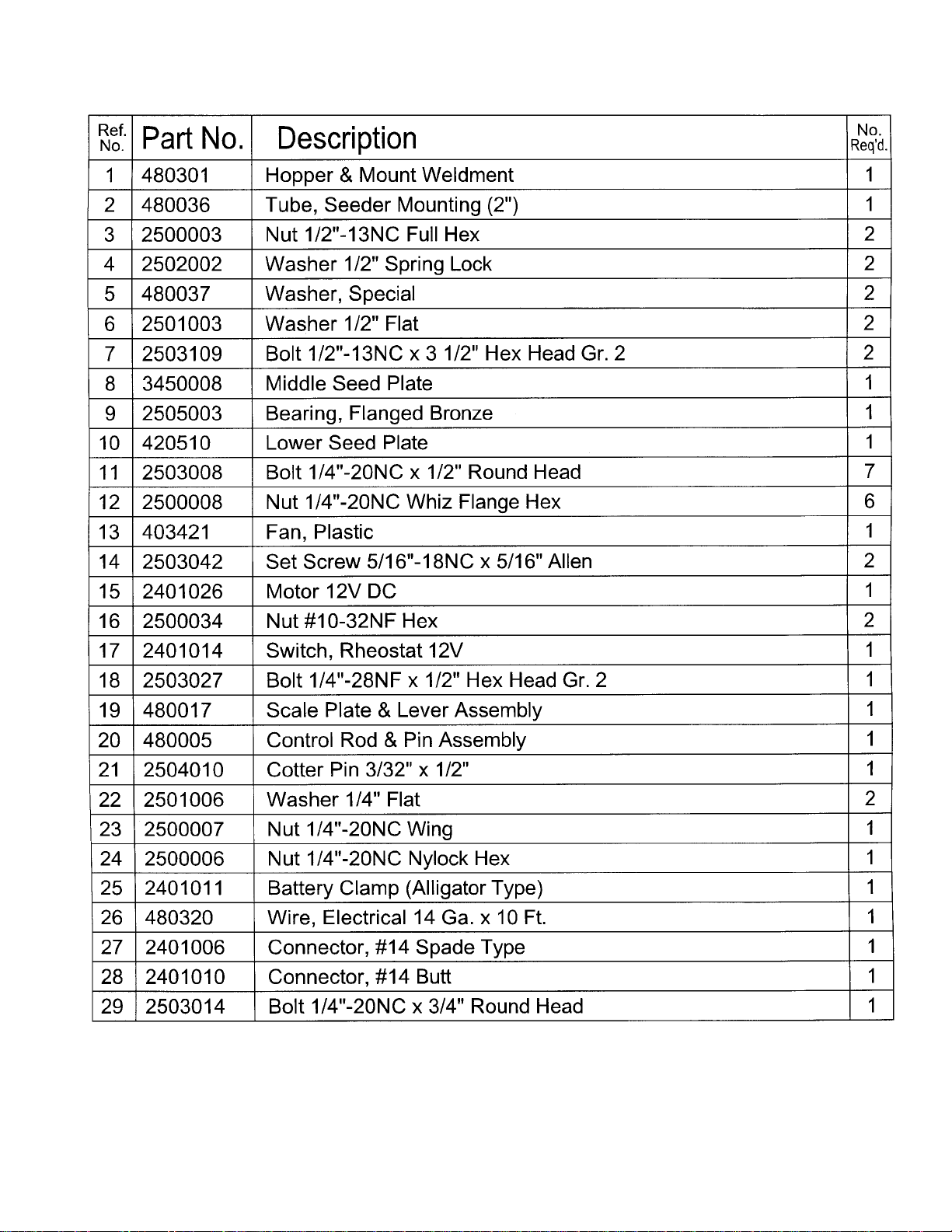
two special square washers (Ref. #5) are to reinforce the
channel bracket on the seeder. Install the lock washers
and nuts and tighten the bolts.
Refer to the instructions for all units, wiring and
operation.
to the tractor fender or some other convenient place. If
you are using a truck, the flat surface on the upper edge
of the bed can be used. Adjust the braces so seeder sets
level or slightly tilted forward, then tighten the clamps.
ES-33
The scale plate and lever assembly is folded and bolted
to the seeder frame to prevent shipping damage. Unbolt
and unfold the lever and control rod. Bolt the scale plate
and control rod assembly on the front of the main frame,
using the 1/4” – 20 x 1/2” bolts provided. Swing the upper
half of the lever up into position (as shown in parts drawing). Replace the bolts and tighten securely.
Insert the control rod through the hole in the seed gate
control plate (middle plate) and secure with the 3/32” x 1/2”
cotter pin provided.
The openings in the hopper bottom (seed gate) are regulated by the control rod and the scale plate lever. Put
the seed gate middle plate into the closed position.
Loosen the control rod adjustment bolt (this bolt connects the lever to the control rod and screws into an
adjustment button). The adjustment button should now
be able to slide on the control rod. Then follow brace rod
instructions as in last two paragraphs for ES-1.5.
EXTENSION HOPPER
Position the hopper extension sides as in figure “B”. As
you position each side, insert the corner angle rod in
each pocket as shown in figure “C”. After these are in
place, insert all the bolts and tighten. Remove the cap
plugs in the seeder hopper. (NOTE: If there is a possibility of using seeder as a 3 bushel, then cap plugs should
be saved.) Position the extension hopper in the seeder
hopper and bolt it in place.
Be sure your tractor or vehicle is in good condition
and properly equipped with counterweights if
required. Read all the safety precautions and make
sure all vehicle operators are familiar with the safety
rules of vehicle operation.
CAUTION!
INSTRUCTIONS
Page 6
INSTRUCTIONS (continued)
ALL UNITS
NOTE: If the paint on the control rod does not allow the
button to slide on the control rod, it may be necessary to
sand some of the paint off with emery paper.
With the seed gate (middle plate) in the closed position,
place the scale plate lever in the closed position.
Retighten the adjustment bolt so that the adjustment button is tight on the control rod.
Move the lever and check to see that the seed gate
(middle plate) is moving with the lever.
Place the lever at the desired setting on the scale plate
and locate the stop bolt so that each time the lever is
pulled to the open position it will be at the same position.
Tighten the stop bolt.
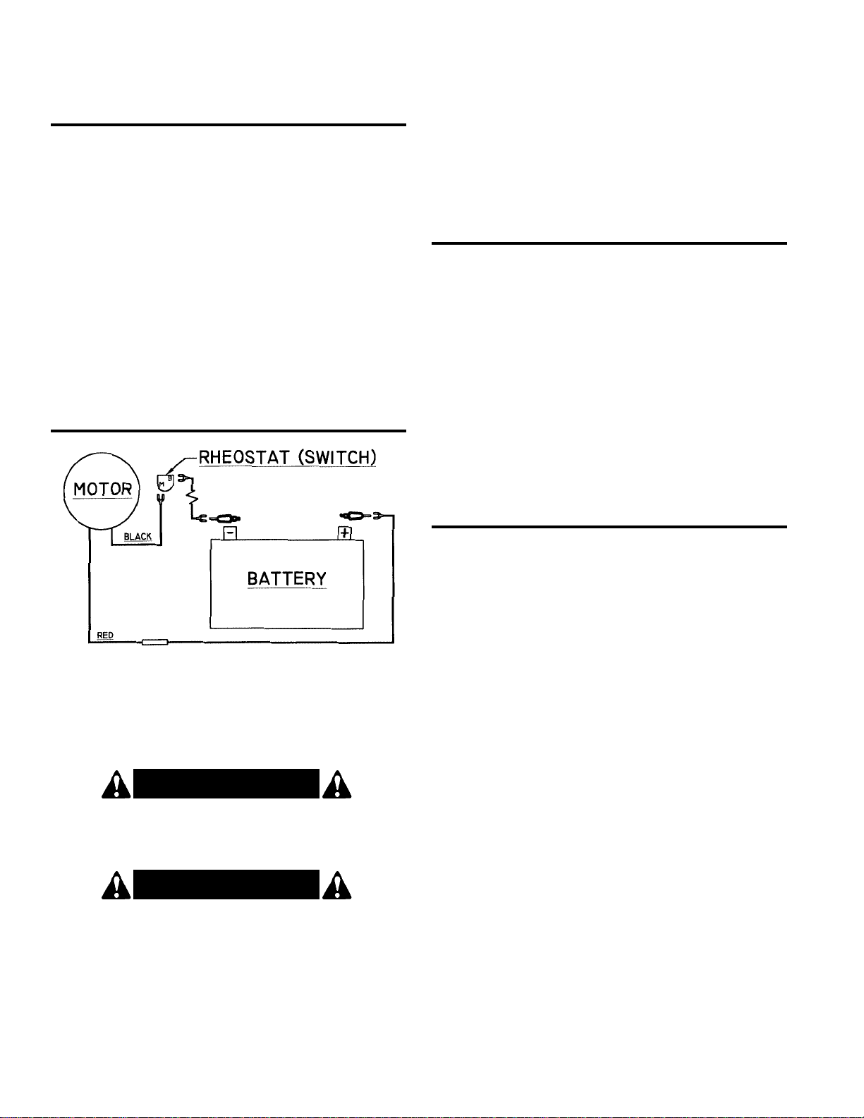
WIRING
The fan motor is for use on 12 volt electrical systems.
The motor will draw approximately 3 amps full load.
Mount the rheostat switch within easy reach of the
driver. To prevent polarity problems, run both wires to the
battery , rather than grounding through the chassis frame.
PREPARATION
• Know your controls and how to stop tractor, engine, or
pickup quickly in an emergency. READ THIS
MANUAL AND THE ONE PROVIDED WITH YOUR
TRACTOR.
• Any person who operates this equipment must be
instructed in and be capable of the safe operation of
the tractor, implement and all controls.
• Ensure implement is properly mounted, adjusted and
in good operating condition.
• Ensure that all safety shielding and safety signs are
properly installed and in good condition.
O PE R ATION
Refer to the electrical schematic above. Strip approximately 1/2” of insulation from the ends of the wires and
crimp on the terminals as shown. For best results, solder
the connections using electrical grade solder. Attach the
wires to the rheostat switch and battery as shown.
CAUTION!
Always disconnect negative (–) cable first and
connect it last.
CAUTION!
Always stop engine before disconnecting or
connecting battery cables or servicing battery.
1. Check the register of the control lever with the seed
gate (material gate). With the seed gate closed, the
control lever indicator should so indicate. If it does not,
you can adjust the adjustment button on the control
rod.
2. DO NOT FILL HOPPER (especially with fertilizer) and
transport over long distances, as it may result in packing, causing poor or erratic discharge.
3. FOR BEST RESULTS use pelletized fertilizer, as it
has little tendency to lump and cause little or no dust.
4. Be sure to sift or break up lumps found in some types
of granular fertilizer before filling hopper.
5. Do not use on windy days, especially when spreading
fine grass seed.
6. Be extremely careful if you are spreading herbicides,
as there is the possibility of wind drift or overthrow into
area that serious crop/shrub damage could occur.
Follow precautions on package.
7. The spreader will not work with rock salt. It will
spread granular calcium chloride if dry and freeflowing.
When properly connected, the fan should rotate in a
clockwise direction, looking down on the fan. The first
position on the rheostat switch is full speed, which will be
used for most seeding applications. The second position
is variable speed, which can be used to reduce the
spread width.
8. When broadcasting fertilizer, always start vehicle in
motion before opening feed gate. (Do not allow
vehicle to sit stationary with feed gate open.) If fertilizer is accidentally deposited too heavily in a small
area, soak down thoroughly with garden hose or
sprinkler to prevent burning.
5
Page 7

6
O P ERATION (continued)
Set out two markers 88 feet apart. Select proper gear
and adjust throttle speed to give the following travel
time as shown between the markers.
1 MPH will travel 88 feet in 60 seconds
4 MPH will travel 88 feet in 15 seconds
6 MPH will travel 88 feet in 11.2 seconds
8 MPH will travel 88 feet in 7.5 seconds
After adjusting throttle setting to give speed as
desired, mark throttle position in some convenient
manner to indicate selected speed. NOTE: After
selecting speed, be sure vehicle engine is running fast
enough for generator to properly charge battery. On
some vehicles it may be necessary to operate in a
lower gear to maintain an adequate engine speed for
charging battery.
4. You are now ready to make a trial turn to assure
accurate results. Close the hopper and put in a predetermined amount of the material to be spread.
Spread this and check the results. Make final adjustments to obtain desired results.
SPREADING INSTRUCTIONS
1. The opening in the hopper bottom is regulated by the
control lever. The size of the opening is determined by
the calibrated scale. Place the control lever at the
desired setting and adjust the stop bolt.
2. Check rate chart for suggested setting for material
type to be spread.
3. Width of spread depends upon the tractor PTO speed
and the weight of the material. The heavier the material, the wider the spread. The table shows width of
spread at full fan rpm, so the width will vary according
to the speed of your motor. The rheostat switch can be
used to slow the speed of the fan in order to obtain a
narrow spread width.
For accurate spreading, calibrate your tractor to
operate at the desired speed. Acalibrated speedometer is the best and most accurate. If your tractor or
vehicle does not have a speedometer or its accuracy
is questionable, then you may calibrate in the
following manner:
MAINTENANCE
This seeder will give long service with proper care.
Keep all of the bolts tightened well. Clean the seeder
thoroughly before storing it, especially when corrosive
materials are used. For best results, after using corrosive
material clean the seeder after each use. Wash it with
clear water or ammonia solution, then wipe it down completely with an oily rag. Put a few drops of oil on the seed
plate and work it back and forth to protect these parts.
Always store seeder/spreader in a clean, dry place.
Before using, check to make sure all nuts and bolts are
tight.
Paint any bare metal or rusty spots for longer life.
WARNING!! When washing the seeder,
completely cover the motor to protect it
from water or corrosive solutions. If the
motor is not protected, damage may occur.
INSTRUCTIONS (continued)
CAUTION!
KEEP ALL PERSONS AWAY FROM THE ROTATING
SPREADERS FAN! NEVER OPERATE WHEN ANYONE IS WITHIN 50 FEET OF SEEDER/SPREADER.
A heavy load can cause instability in driving a tractor. Make sure the front of the tractor is properly
counter-balanced with weights. Always drive slowly
– especially around turns. An unstable tractor could
steer badly and possibly tip over, causing injury or
death.
W ARNING!
Do not attempt to use your fingers to clear a jam.
Accidental closing of the feed gate could pinch or
amputate a finger. Be sure that the electric motor is
shut off and the power is disconnected before doing
any adjustment or repair.
CAUTION!
Page 8
INSTRUCTIONS (continued)
OPTIONAL ES-1.5 PKP
ROPE CONTROL PACKAGE
INSTRUCTIONS
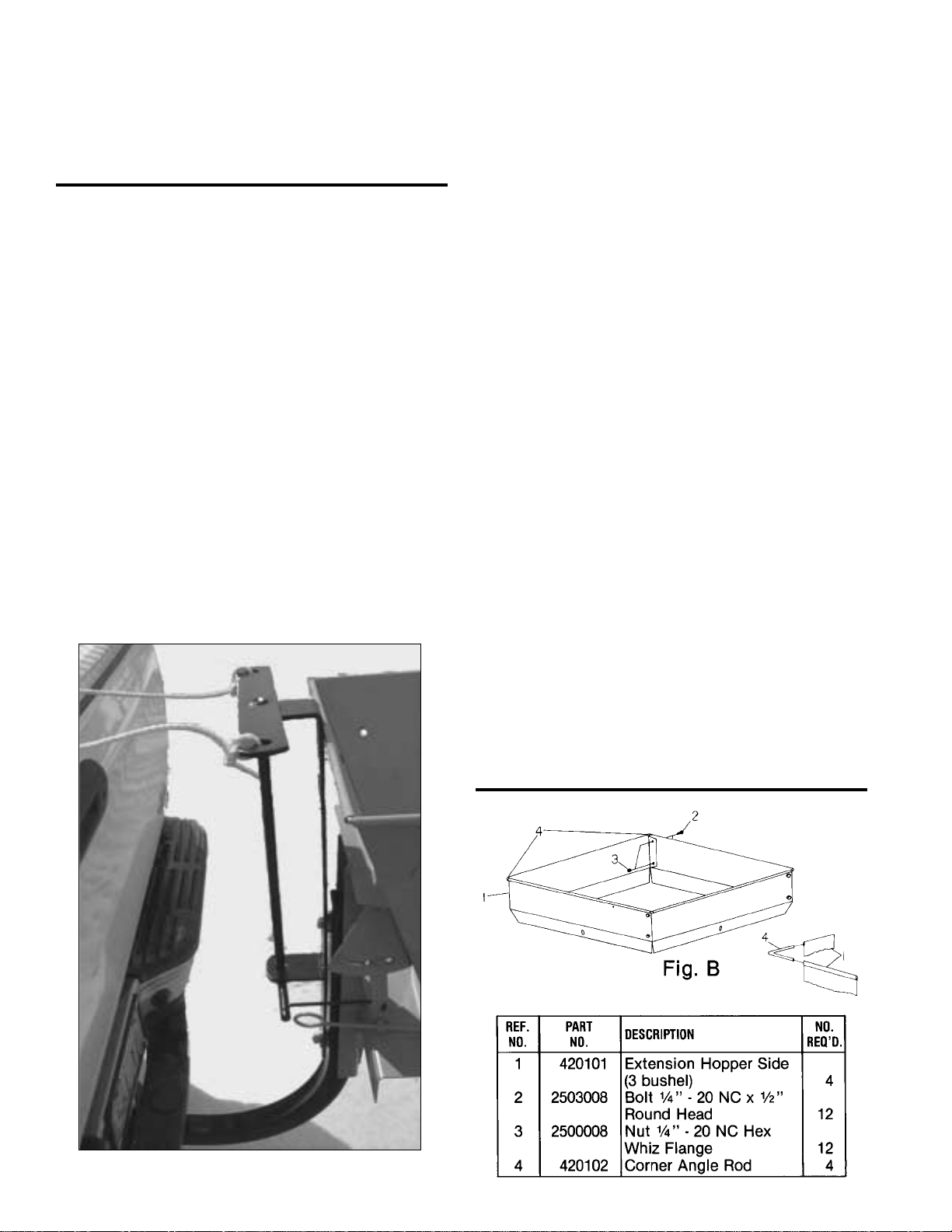
This optional package allows operators to open or
close the seed gate of the ES-1.5 PKP seeder from the
cab of the pickup truck.
One rope will open the seed gate when pulled and the
other will close it.
Refer to figure “A” to see the relationship of the rope
control frame to the seeder.
The rope control frame mounts on the front side of the
2” seeder mount tube with the same 1/2” x 31/2” hex bolts
that hold the seeder.
NOTE: Make sure the rope control lower pivot arm is
on the same side as the scale plate assembly of the
seeder before bolting in place.
NOTE: The rope control bracket may come up against
the forward top edge of the seed hopper. There should
be a slight space between these parts. If necessary,
remove the rope control bracket and install two or three
1
/2” flat washers between the backside of the rope control
bracket and the 2” mounting tube.
Extra 1/2” flat washers are included with the rope control
bracket in case they are needed.
Install the 1/4” rod connecting link between the scale
plate lever (use the unused hole in the lever) the lower
pivot arm of the rope control pivot. Install the 3/32” cotter
pins in each end of the connecting link and spread the
cotter pins.
Order part number 480040 for the optional rope pull
bracket assembly.
Tie one end of the rope to one end of the upper pivot
arm and the other rope to the other end of the pivot arm.
Separately run the ropes to the cab of the pickup. If the
pickup has a sliding rear window, the rope can be run
through the window.
The ropes can also be run along the left side of the
pickup and looped around the side mirror bracket. This
will allow operator control by reaching through the open
side window.
NOTE: If the ropes are located to the side mirror, a
simple loop with some slack in the rope will allow the
operator to easily remove the loop from the side mirror
bracket for easy access in and out of the left door.
NOTE: Cut off any additional length of rope not
required and make sure no ends of the loop can catch in
brush or tree limbs. Damage to the seeder and rope
control could occur.
Fig. A
OPTIONAL USX-3
3 BU. EXTENSION KIT
R E PAIR PA RT S
7
Page 9
8
INSTRUCTIONS (continued)
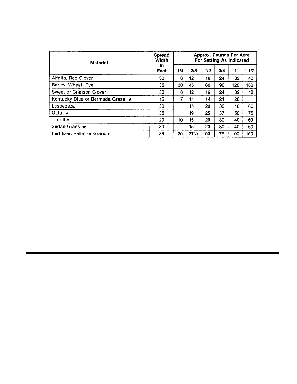
The spread width indicated on this chart is possible if spinner is operated 30 inches above the
ground. Seeder should be level or tilted forward slightly.
NOTE:
Spread Chart settings are approximate – always make trial run to check actual application rate.
The amount of seed or fertilizer broadcast depends on the size of the hopper opening and the speed of the tractor.
The table shown is an approximate guide based on a tractor speed of 4 MPH, so adjust for different speeds.
. NOTE:
Since there is no agitator in the seed hopper, these materials will bridge at narrow seed gate settings and
cause erratic seeding rates. If bridging occurs at wider seed gate settings, cleaning the seed or blending with
a small dense seed such as clover may help. Amix of dry sand with the seed (50/50 mix) can sometimes solve
the problem.
HELPFUL TROUBLE-SHOOTING TIPS
1. Not feeding even –
A. Seed gate opening may be set too close for the
material being spread. To overcome, set the opening larger and driver faster to obtain same spread
rate.
B. Check material for foreign matter or lumps.
D. Set screw loose or missing on fan hub.
E. Too windy for material being spread.
F. Agitator problems – check tips above, under “Not
feeding even.”
G. Operator not spacing spread runs properly for
correct overlap.
For best results, cover area twice over at one-half
recommended material usage rate, the second
time over to run halfway between first spreading
width or in a criss-cross pattern. This method
allows the most complete and even coverage, as
well as to give operator a chance to adjust gate
setting to compensate for too thin or too heavy a
covering the first time over.
2. Poor spread –
A. Too much speed (over 560 PTO rpm) can cause
uneven spread.
B. Spreader fan speed too slow (under 520 rpm) will
result in a narrow spread.
C. Bent or broken fan blades.
O PE R ATIONAL SPREADING CHART
(Calibrated at 4 MPH ground speed)
Page 10
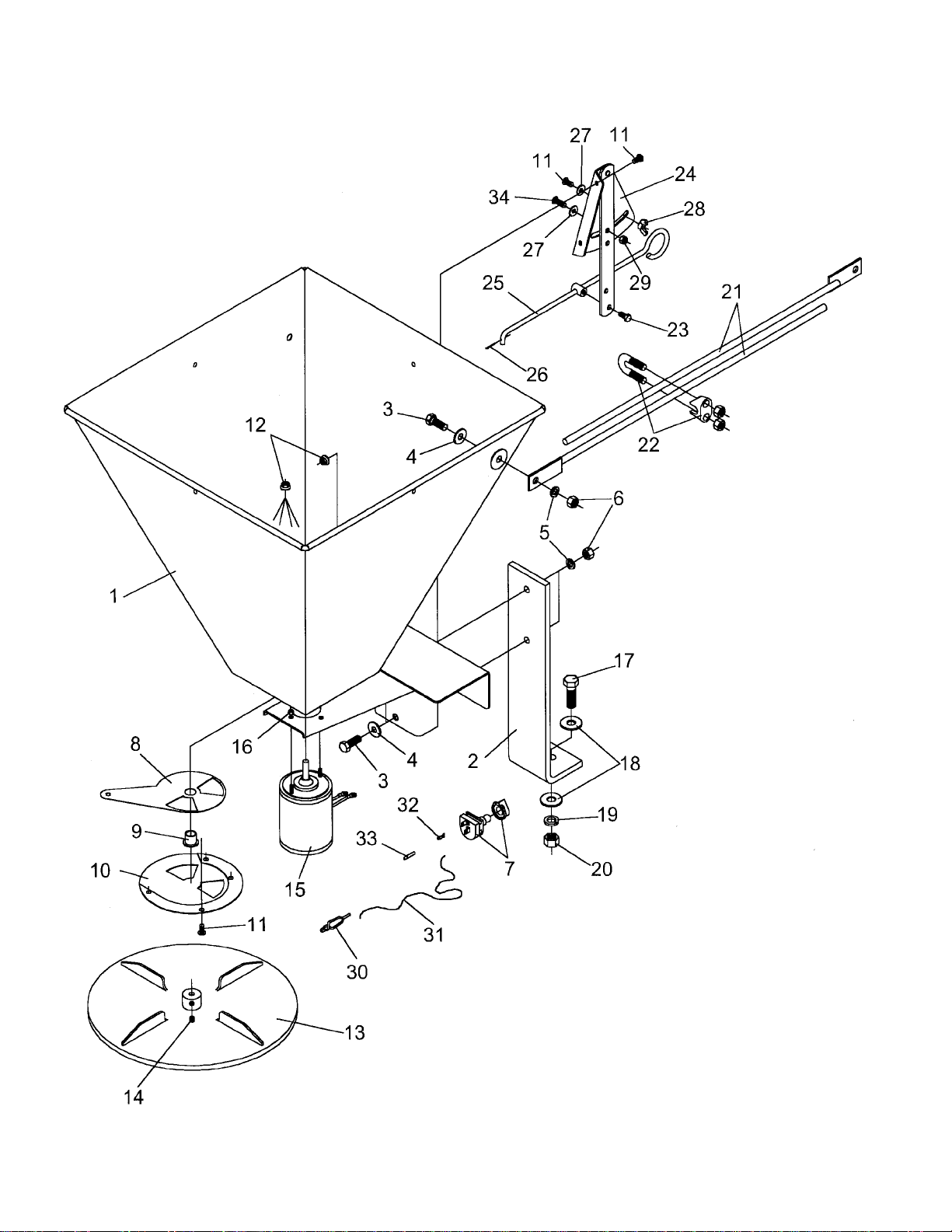
ES-1.5 SEEDER PA RTS DRAWING
9
Page 11
10
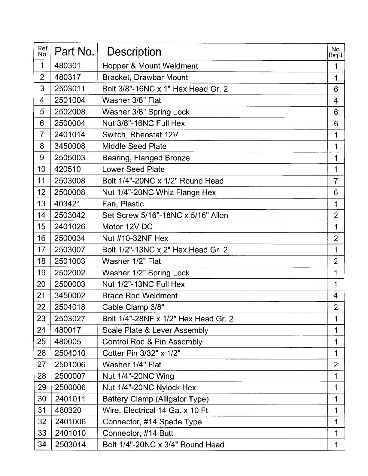
ES-1.5 SEEDER PA RTS LIST
Page 12
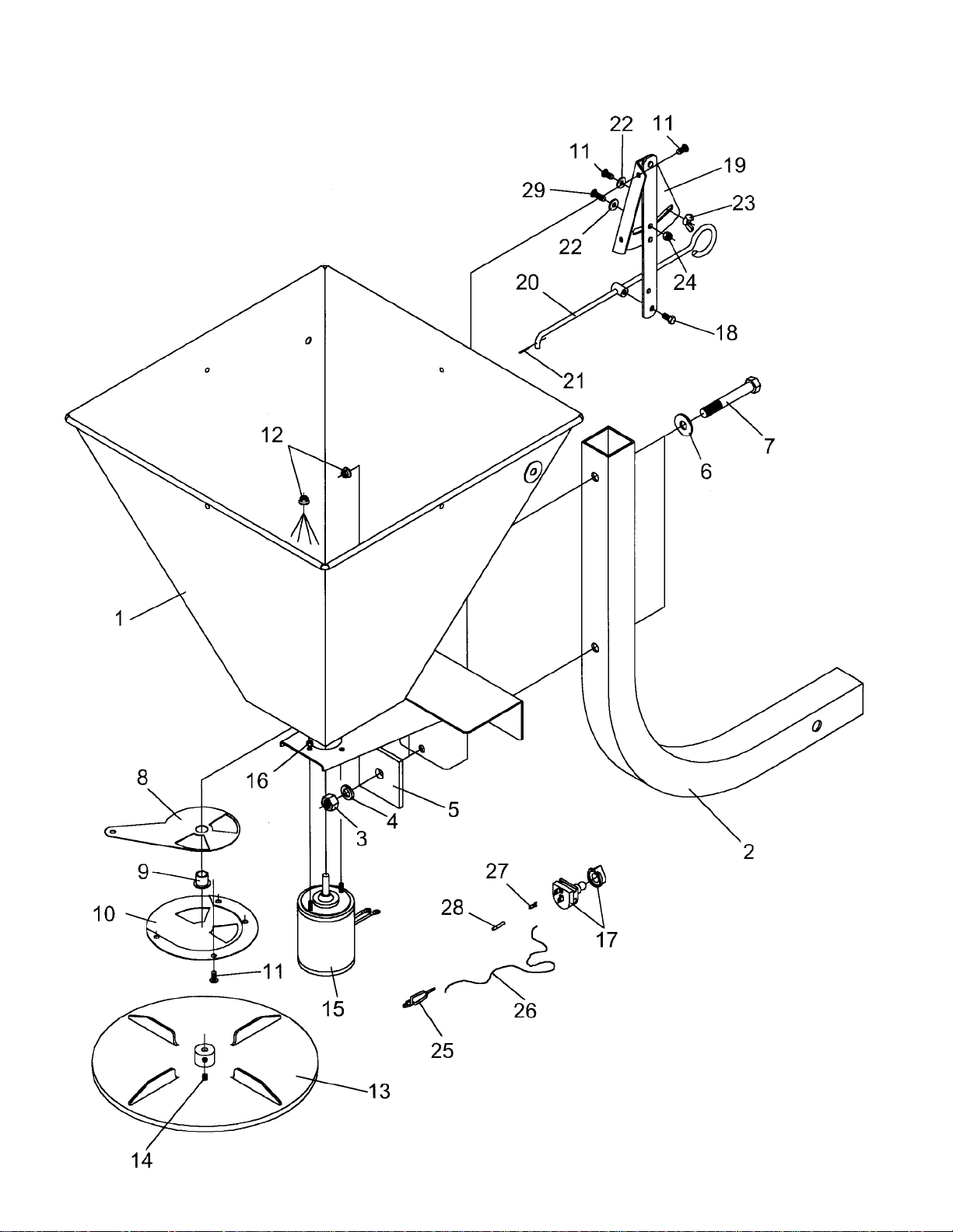
ES-1.5 PKP SEEDER PA RT S D RAWING
11
Page 13
12
ES-1.5 PKP SEEDER PA RTS LIST
Page 14
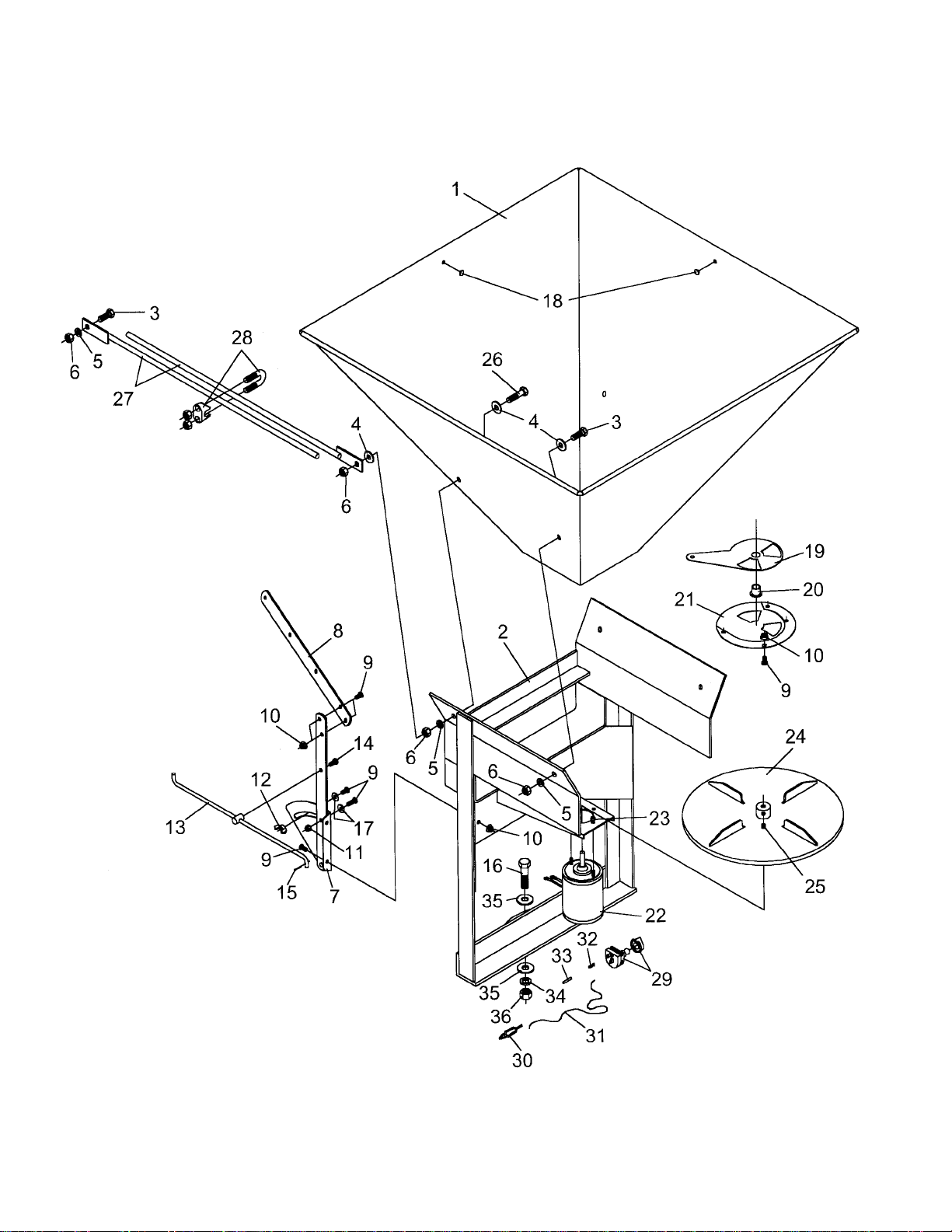
13
Page 15
14
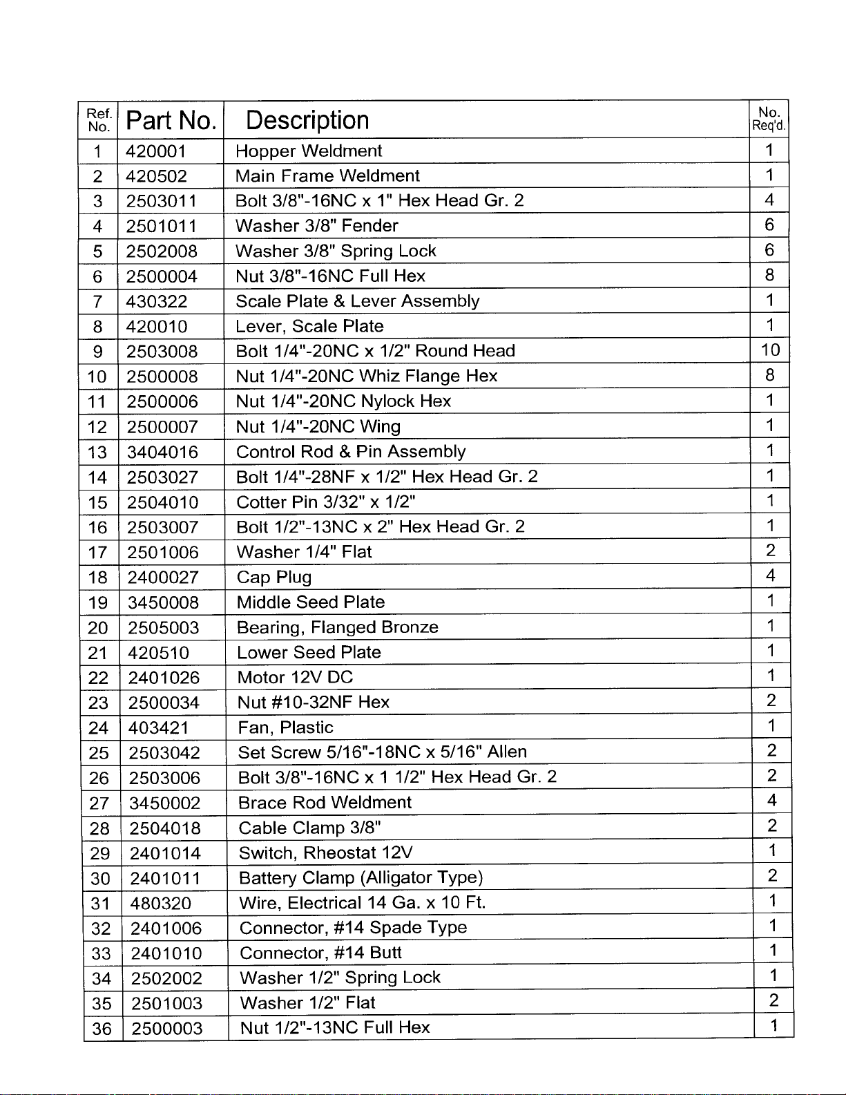
ES-33 SEEDER PA RTS LIST
Page 16

SAFETY PRECAUTIONS
MOST ACCIDENTS OCCUR BECAUSE OF NEGLECT OR CARELESSNESS.
AVOID NEEDLESS ACCIDENTS BY FOLLOWING ALL OF THE SAFETY PRECAUTIONS LISTED BELOW.
• Machinery should be operated only by those who are
responsible and are authorized to do so.
• Stop the engine, lower all equipment, lock the brakes,
and remove the ignition key before dismounting from the
tractor.
• Never stand between tractor and implement while tractor
is being backed to hitch.
• Loose fitting clothing should not be worn, to avoid catch-
ing on various parts.
• Detach implement in area where children normally do not
play.
• When performing adjustments or maintenance on an
implement, first lower it to the ground or block it securely
at a workable height.
• Only a qualified operator should be permitted on tractor
when in operation; no riders allowed.
• Make certain everyone is in the clear before starting
tractor or raising or lowering equipment.
• Operate the tractor and implement only while seated in
the driver’s seat.
•
Reduce speed when transporting mounted implements
to avoid bouncing and momentary loss of steering
control.
• A heavy load can cause instability of the tractor. Use
extreme care during road travel. Slow down on turns and
watch out for bumps. Tractor may need front counterweights to counter-balance the weight of the implement.
• Reduce speed on hillsides or curves so there is no
danger of tipping.
• Avoid driving too close to the edge of ditches or creeks.
• Do not transport implement on public roads without
reflectors and slow moving vehicle emblem in daylight
and with approved warning lights at night and other
periods of poor visibility.
• Due to the width of some implements, use extra caution
on highways, farm roads, and when approaching gates.
• Always be sure the implement is in the proper position for
transport.
• Keep alert and watch the front as well as the rear when
working with the implement.
OWNER’S/
OPERATOR’S
MANUAL
MODEL NO.’s
ES-1.5
ES-1.5 PKP
ES-33
WHEN ORDERING
REPAIR PARTS,
ALWAYS GIVE
THE FOLLOWING
INFORMATION:
1. PART NUMBER
2. PART DESCRIPTION
3. MODEL NUMBER
4. NAME OF ITEM
STATEMENT OF POLICY
It is the policy of Farm Star to improve its products where it is possible and
practical to do so. Farm Star reserves the right to make changes or improvements in design and construction at any time, without incurring the obligation
to make these changes on previously manufactured units.
ELECTRIC SEEDER
LIMITED WARRANTY
Farm Star warrants its implements, parts and accessories to be free from defects in
materials and workmanship for a period of six (6) months from date of purchase. Upon
written approval, Farm Star will repair or exchange without charge any part, which
examination by
This does not apply to (1) parts that have worn out in normal use, (2) parts broken
because of improper assembly or operation by the customer, (3) parts accidentally
damaged, (4) failure of parts traceable to improper care, (5) parts failing through use
of implement for purposes other than those for which it was designed.
The obligations assumed by Farm Star and the limitations expressed herein are in
lieu of all other warranties expressed or implied.
Farm Star
or its authorized agent, shall disclose to be defective.
upon
MARCH 2002
FS-SS008-OG
FARM STA R
P.O. BOX 100 LITCHFIELD, IL 62056-0100 (217) 324-5973
WEB: http://www.farmstar.com E-MAIL: [email protected]
 Loading...