

Page 1
OWNER’S/
OPERATOR’S
MANUAL
MODEL NO.’s
DCR-4 MCR-6
DCR-5 MCR-7
LRHD-6
LRHD-7
LRHD-8
CAUTION
For Safe Operation
Read Rules And
Instructions Carefully
SINO LEEINGLES, PIDA AYUDA
A AIGUIEN Q UE SI LO LEA
PARA QUE LE TRADUZCA LAS
MEDIDAS DE SEGURIDAD.
CAUTION
THE FOLLOWING SAFETY PRECAUTIONS SHOULD BE THOROUGHLY UNDERSTOOD
BEFORE ATTEMPTING TO BEGIN ASSEMBLING THIS MACHINE
1. Select an area for assembly that is clean and free of an y
debris which might cause persons w orking on the
assembly to trip.
2. Do not lift hea vy par ts or assemb lies. Use cr ane, jac k,
tackle, fork trucks or other mechanical devices.
3. Preview the assemb ly instr uctions in y our oper ator’s
manual before proceeding further.
4. If the assembly instructions call for parts or assemblies to
be blocked up, use only blocking material that is in good
condition and is capab le of handling the w eight of the
assembly to be b locked. Also insure that the b locking
material is on a clean, dr y surface.
5. Never put hands, or an y par t of body, under b locked up
assemblies if at all possible.
6. After completing assemb ly, thoroughly inspect the
machine to be sure that all n uts, bolts, hydraulic fittings
or any other f astened assemblies have been thoroughly
tightened.
7. Before oper ating the machine , thoroughly read the
operation section of your operator’s manual.
8. Before oper ating, read the maintenance section of y our
operator’s man ual to be sure that an y par ts requir ing
lubrication, such as gearbo xes, are full, to a void an y
possible damage.
9. Before operating equipment – If y ou ha ve an y
questions regar ding the pr oper assemb ly or
operation, contact your dealer or representative.
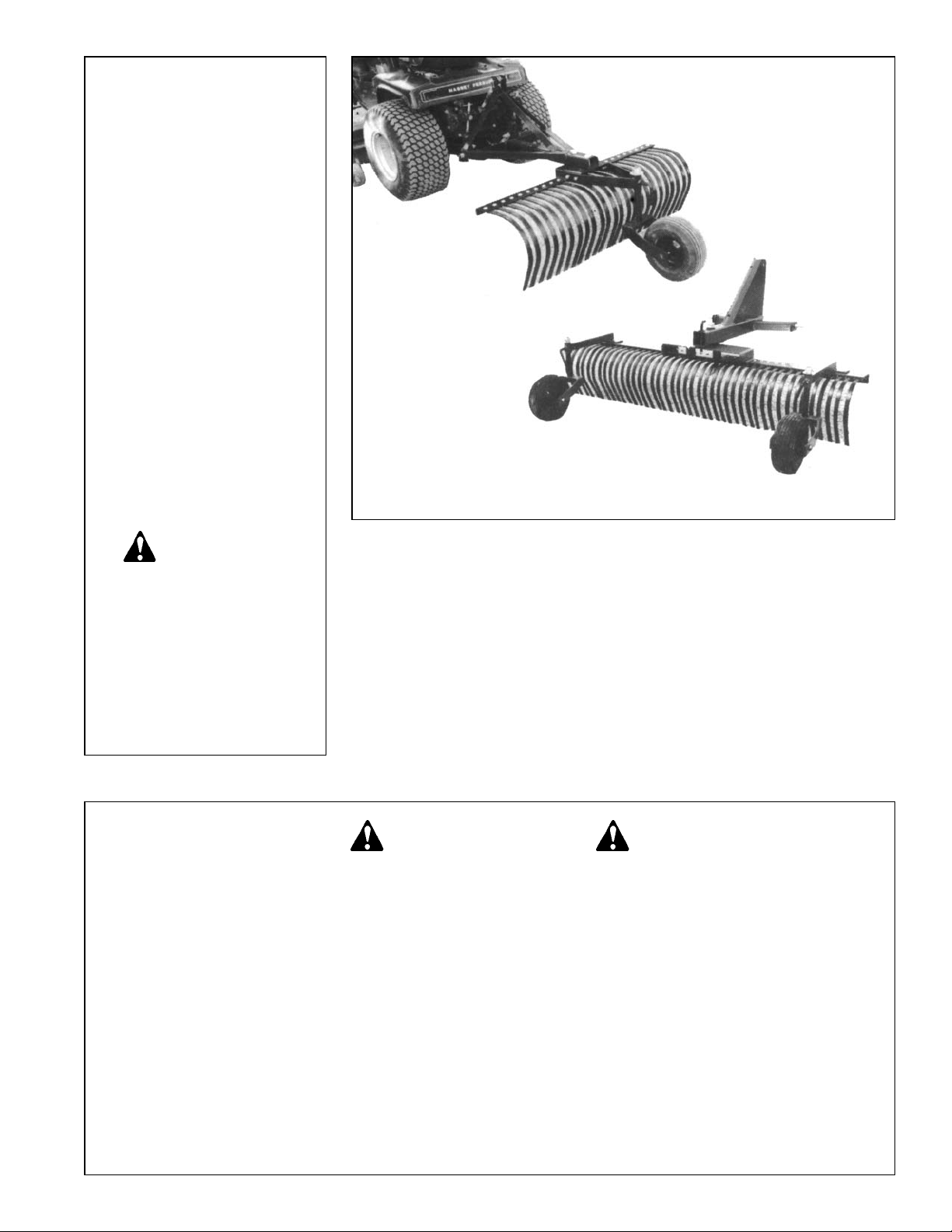
3 PT. LANDSCAPE RAKE
Safety Instructions Assembly & Mounting
Tractor Preparation Maintenance
Operating Instructions Repair Parts
DCR-4
LRHD-7
(Rakes shown with optional gauge wheels)
Page 2

1
TABLE OF CONTENTS
WARRANTY . . . . . . . . . . . . . . . . . . . . . . . . . . . . . . . . . . . . . . . 2
SAFETY INFORMATION . . . . . . . . . . . . . . . . . . . . . . . . . . . . . 3
SAFETY SIGNS . . . . . . . . . . . . . . . . . . . . . . . . . . . . . . . . . . . . 6
PREPARATION INSTRUCTIONS . . . . . . . . . . . . . . . . . . . . . . 7
ASSEMBLY . . . . . . . . . . . . . . . . . . . . . . . . . . . . . . . . . . . . . . . 7
OPERATING INSTRUCTIONS . . . . . . . . . . . . . . . . . . . . . . . . . 9
SERVICE INSTRUCTIONS . . . . . . . . . . . . . . . . . . . . . . . . . . . 10
TROUBLE-SHOOTING . . . . . . . . . . . . . . . . . . . . . . . . . . . . . . 11
PARTS DRAWINGS & LISTS . . . . . . . . . . . . . . . . . . . . . . . 12-14
SINO LEEINGLES, PIDA A YUDA A
AIGUIEN QUE SI LO LEA PARA QUE
LE TRADUZCA LAS MEDID AS DE
SEGURIDAD.
STATEMENT
OF POLICY
It is the policy of )DUP6WDU
Io improve its products whereLW is
possib
le and pr actical to do so.
)DUP6WDUreserves the right to
makechangesorimprovements
in design and construction at
any time , without incurring the
obligation to mak ethese chan
gesonpreviouslymanufactured
units.
TO THE OWNER:
Read this man ual bef ore using y our Landscape Rak e. This man ual is pro vided to giv e y ou the necessar y
operating and maintenance instructions for keeping your Landscape Rake in top operating condition. Please read
this manual thoroughly. Understand what each control is f or and ho w to use it. Observe all safety signs on the
machine and noted throughout the man ual for saf e operation of implement. Keep this man ual handy for ready
reference.
Like all mechanical products, it will require cleaning and upkeep.
Use only gen uine )DUP6WDU service par ts. Substitute par ts will v oid the w arranty and ma y not meet
standards required f or safe and satisf actory operation. Record the model and ser ial number of your Landscape
Rake here:
Model:________________________________________ Serial Number:_______________________________
RETAIL CUSTOMER’S RESPONSIBILITY
It is the Retail Customer and/or Operator’ s responsibility to read the Operator’ s Man ual, to operate ,
lubricate, maintain, and store the pr oduct in accor dance with all instructions and saf ety pr ocedures.
Failure of the operator to read the Operator’s Manual is a misuse of this equipment.
It is the Retail Customer and/or Operator’s responsibility to inspect the product and to have any part(s)
repaired or replaced when continued operation would cause damage or excessive wear to other parts or
cause a safety hazard.
It is the Retail Customer’s responsibility to deliver the product to the authorized )DUP6WDU Dealer, from
whom he pur chased it, for ser vice or replacement of def ective par ts whic h are co vered b y warranty.
Repairs to be submitted for warranty consideration must be made within forty-five (45) days of failure.
It is the Retail Customer’s responsibility for any cost incurred by the Dealer for traveling to or hauling
of the product for the purpose of performing a warranty obligation or inspection.
Page 3

2
LIMITED WARRANTY
✯ ✯ ✯ ✯ ✯ ✯ ✯ ✯ ✯ ✯ ✯ ✯ ✯ ✯ ✯ ✯ ✯ ✯ ✯ ✯ ✯ ✯ ✯ ✯ ✯ ✯ ✯
Farm Star warrants to the or iginal purchaser of an y new 3 Pt. Landscape Rake, that the equipment be free
from def ects in mater ial and w orkmanship f or a per iod of six (6) months f or non-commercial, state , and
municipalities. Use sixty (60) days for commercial use from date of retail sale .
Replacement or repair par ts installed in the equipment covered by this warranty are warranted for ninety (90)
days from the date of purchase of such par t or to the e xpiration of the applicab le new equipment w arranty
period, whichever occurs later.
Such parts shall be provided at no cost to the user during regular working hours. Farm Star reserves the right
to inspect any equipment or parts which are claimed to have been defective in material or workmanship.
DISCLAIMER OF IMPLIED WARRANTIES & CONSEQUENTIAL DAMAGES
Farm Star’s obligation under this w arranty, to the e xtent allowed by law, is in lieu of all w arranties, implied or
expressed, including implied warranties of merchantability and fitness for a particular purpose and any liability f or incidental and consequential damages with respect to the sale or use of the items w arranted. Such
incidental and consequential damages shall include b ut not be limited to: transportation charges other than
normal freight charges; cost of installation other than cost approved by Farm Star; duty; taxes; charges for normal service or adjustments; loss of crops or any other loss of income; rental of substitute equipment, expenses due to loss, damage, detention or delay in the delivery of equipment or parts resulting from acts beyond the
control of Farm Star.
THIS WARRANTY SHALL NOT APPLY:
1. To vendor items which carry their own warranties, such as hydraulic motors, tires, and tubes.
2. If the unit has been subjected to misapplication, ab use, misuse, negligence, fire or other accident.
3. If parts not made or supplied by Worksaver have been used in connection with the unit, if, in sole judgement of Farm Star such use affects its performance, stability, or reliability.
4. If the unit has been altered or repaired outside of an author ized Farm Star dealership in a manner which,
in the sole judgement of Farm Star affects its performance, stability or reliability.
5. To nor mal maintenance ser vice and nor mal replacement items such as gearbo x lubricant, hydraulic fluid,
worn tines, or to normal deterioration of such things as belts and e xterior finish, due to use or e xposure.
6. To expendable or w ear items such as tines , chains, sprockets, belts , springs and other items that in the
company’s sole judgement is a wear item.
NO EMPLO YEE OR REPRESENT ATIVE OF FARM STAR IS A UTHORIZED TO CHANGE THIS
WARRANTY IN ANY WAY OR GRANT ANY O THER WARRANTY UNLESS SUCH CHANGE IS MADE IN
WRITING AND SIGNED BY FARM STAR’S SERVICE MANAGER, POST OFFICE BOX 100, LITCHFIELD,
ILLINOIS 62056-0100.
✯ ✯ ✯ ✯ ✯ ✯ ✯ ✯ ✯ ✯ ✯ ✯ ✯ ✯ ✯ ✯ ✯ ✯ ✯ ✯ ✯ ✯ ✯ ✯ ✯ ✯ ✯
Page 4

3
To the Owner/Operator/Dealer
All implements with moving parts are potentially hazardous. There is no substitute for a cautious, safe-minded operator who recognizes the potential hazards and follows reasonable safety practices. The manufacturer has designed this
implement to be used with all its saf ety equipment properly attached to minimize the chance of accidents.
BEFORE YOU START!!
Read the safety messages on the implement and sho wn in your manual.
Observe the rules of safety and common sense!
THIS SAFETY ALER T SYMBOL IDENTIFIES IMPOR TANT
SAFETY WARNING MESSAGES. CAREFULLY READ EACH
WARNING MESSAGE THA T FOLLOWS. FAILURE T O
UNDERSTAND AND OBEY A SAFETY WARNING, OR
RECOGNIZE A SAFETY HAZARD , COULD RESUL T IN AN
INJURY OR DEA TH TO YOU OR O THERS AR OUND YOU.
THE OPERATOR IS ULTIMATELY RESPONSIBLE FOR THE
SAFETY OF HIMSELF , AS WELL AS O THERS, IN THE
OPERATING AREA OF THE TRACTOR AND A TTACHED
EQUIPMENT.
IMPORTANT SAFETY INFORMATION!
Working with unfamiliar equipment can lead to careless injur ies. Read this man ual, and the man ual for y our tractor,
before assembly or operating, to acquaint yourself with the machines. It is the implement owner’s responsibility, if this
machine is used b y an y person other than y ourself, is loaned or rented, to mak e certain that the oper ator, pr ior to
operating:
1. Reads and understands the oper ator’s manuals.
2. Is instructed in safe and proper use.
The use of this equipment is subject to cer tain hazards which cannot be protected against b y mechanical
means or product design. All operators of this equipment m ust read and understand this entire man ual, paying particular attention to safety and operating instructions, prior to using. If there is something in this manual
you do not understand, ask y our supervisor, or your dealer, to explain it to you.
THIS SYMBOL MEANS
– ATTENTION!
– BECOME ALERT!
– YOUR SAFETY IS INVOLVED!
UNDERSTAND SIGNAL WORDS
Note the use of the signal w ords DANGER, WARNING
and CAUTION with the safety messages. The
appropriate signal word for each has been selected
using the following guidelines:
DANGER: Indicates an imminently hazardous situation
that, if not avoided, will result in death or ser ious injury.
This signal word is to be limited to the most e xtreme
situations typically for machine components which, for
functional purposes, cannot be guarded.
If y ou ha ve questions not ans wered in this man ual or require additional copies or the man ual is damaged, please
contact your dealer or the manufacturer directly.
WARNING: Indicates a potentially hazardous situation that, if not avoided, could result in death
or serious injury, and includes hazards that are
exposed when guards are removed. It may also
be used to aler t against unsafe practices.
CAUTION: Indicates a potentially hazardous situation that, if not avoided, may result in minor or
moderate injury. It may also be used to aler t
against unsafe practices.
Page 5

4
SAFETY INSTRUCTIONS (continued)
All equipment is potentially hazardous . There is no substitute f or a cautious , saf e-minded oper ator who
recognizes potential hazards and follows reasonable safety practices.
This equipment is dangerous to children and persons unf amiliar with its operation. The operator should be a
responsible adult familiar with farm machinery and trained in this equipment’ s operations. Do not allow per-
sons to operate or assemble this unit until they have read this manual and have developed a thorough
understanding of the safety precautions and of how it works.
Only use a po wer unit equipped with a ROPS cab or rollo ver protective structure. Keep foldable ROPS systems in “locked up” position at all times. Keep seat belt fastened.
Always use tw o people to handle hea vy, unwieldy components dur ing assemb ly, installation, remo val, or
moving the implement.
Never place an y par t of y our body where it w ould be in danger if mo vement should occur dur ing assembly,
installation, operation, maintaining, repairing, removal, or moving the implement.
Never place yourself between the tractor and implement while implement is in oper ation.
Do not work under a raised implement unless it is securely blocked or held in position. Do not depend on the
tractor hydraulic system to hold the implement in place .
A hea vy load can cause instability of the tr actor. Use extreme care dur ing tr avel. Slow down on tur ns and
watch out f or b umps. The tr actor ma y need front counter-w eights to counter-balance the w eight of the
implement.
Never use alcoholic be verages or dr ugs which can hinder aler tness or coordination while oper ating this
equipment. Consult your doctor about operating this machine while taking prescription medications.
Do not allow others to ride on the tractor with an operator. Riders are subject to injury such as being struck by
foreign objects or being thro wn off. Riders obstr uct the oper ator’s view resulting in unsaf e operation. Never
allow anyone to ride on the implement!
Before you operate the implement, chec k over all pins , bolts and connections to be sure all are securely in
place. Replace any damaged or worn parts immediately.
Most accidents occur because of neglect or carelessness. Keep all helpers and bystanders fifty feet (50’) from
an operating power unit and attached equipment. Only properly trained people should oper ate this machine.
It is recommended the tr actor be equipped with a Rollo ver Protection System (R OPS) and a seat belt that is
used. Always stop the tr actor, set br ake, shut off the engine , remove the ignition k ey, and lo wer loader and
attachment to the ground before dismounting. Never leave equipment unattended with the engine r unning.
Page 6

5
SAFETY INSTRUCTIONS (continued)
Never allow children to operate or be around equipment.
Use stabilizer bars, adjustable sway chains, or sway blocks on your tractor lift arms to keep the implement from
swinging side to side. Adjust as tightly as practical for best performance.
Keep alert and watch the front as well as the rear when w orking with the implement.
When maneuvering close to b uildings or passing through narro w areas, be sure to allo w sufficient clearance
for the implement.
Do not operate close to ditches or creeks. Slow down when operating over rough ground.
Always be sure the implement is in the fully r aised position when in transport.
When removing, changing the angle, or reversing the rake, be sure that your feet are never under the rake.
Use extreme caution when backfilling deep holes or trenches.
Be careful to avoid catching the rake on stumps or other immovable objects.
Use care when working on slopes.
Avoid excessive speed during operation.
Make adjustments only when the implement is attached to the tr actor.
When using the rake in a reverse position, use extra care. Do not ram rake into piles of dirt. Tractor lift arms
and the r ake are not b uilt to tak e high impact loads in this position. Ramming backwards can also dislodge
operator from seat and/or tr actor controls, resulting in possible serious injury or death.
Always ease the tractor into the load. It may be necessary to reposition and take less “bite” on the material to
move it safely.
Operating spring steel r ake tines may suddenly fling roc ks and clods . Keep all bystanders 50 f eet away and
operator must wear safety glasses.
Stop power unit and equipment immediately upon striking an obstruction. Turn off engine, remove key, inspect,
and repair any damage before resuming operation.
Before leaving operator’s seat, lo wer lift arms and put attachment on the g round. Engage brake, stop engine,
remove key, and remove seat belt.
Never perform service or maintenance with engine r unning.
Watch f or and a void hidden obstr uctions, i.e ., b uried pipes , roc ks, concrete piers , une ven concrete slabs ,
stumps, etc., when operating.
Page 7

6
SAFETY SIGNS
OBEY ALL
SAFETY WARNINGS!!
✔ Keep children away from danger all day, every day.
✔ Please w ork, dr ive, pla y, and liv e each da y with care and
concern f or y our saf ety and that of y our f amily and f ellow
citizens.
Page 8

7
INSTRUCTIONS
WARNING!
Power unit must be equipped with R OPS or ROPS
cab and seat belt. Keep seat belt securel y fastened.
Falling off po wer unit can result in death fr om being
run over or crushed. Keep foldable ROPS systems in
“locked up” position at all times.
Be sure y our tractor and loader is in good condition. Read all the saf ety precautions and make sure
all equipment operator s are familiar with the saf ety
rules of operation.
CAUTION!
TRACTOR REQUIREMENTS
AND PREPARATION
——————————————————
The DCR, MCR, and LRHD Ser ies Landscape Rak es
will fit most Category I) tractors equipped with a standard
3 point hitch. DCR Ser ies r akes will also fit Categor y 0
hitch tractors.
NOTE: Some Categor y 0 tr actors ha ve v ery shor t lift
arms or 5/8” diameter (Cat. 0) lift ar m ball ends. The DCR
Series rakes will fit these tractors if equipped with special
Cat. 0 pullpins. The pins need to be installed to the inside
of the 3 pt. frame.
Check the tractor’s 3 point hydraulic lift system. It should
operate up and down smoothly and hold its position when
set. Refer to your tractor owner’s manual or dealer for any
adjustments necessar y to put the 3 point h ydraulic lift
system in good working order. (I&T shop manuals will list
most specifications and adjustment instr uctions –
available from most farm equipment dealers.)
Tractor should be equipped with stabiliz er bars ,
adjustable sway chains, or sway blocks to keep the implement from swinging side to side.
Smaller size tractors may need front counter w eights to
counter-balance the weight of the implement.
PACKAGING
——————————————————
The landscape rake is shipped as two bundles:
1. Main Frame with pull pins, bolts and nuts.
2. Rake Tine Bar Assembly (Teeth installed).
ASSEMBLY AND MOUNTING
——————————————————
Preview the assemb ly instr uctions and the e xploded
view of the landscape rake in your operator’s manual and
become f amiliar as to ho w the par ts or assemb lies go
together.
Select an area for assembly that is clean and free from
debris.
The two main subassemblies of the landscape rake are
heavy and a wkward to handle . It is recommended that
you have one or two helpers to complete the assembly.
1. On DCR and MCR models, assemble the “A” frame as
shown in the exploded parts view (pg. 12 or pg. 13).
2. It is suggested that y ou mount the main fr ame on the
3 point hitch of y our tr actor bef ore assemb ling the
landscape rake as follows:
a. Lower the 3 point hitch on y our tractor to facilitate
mounting of the main fr ame of the r ake to the
tractor.
b. Insert the lift ar m pins on the main fr ame into the
ball soc kets in the lift ar ms of the tr actor 3 point
hitch. Pin in place with linchpins (not fur nished).
NOTE: On DCR models – if your tractor has a Categor y
0 3 point hitch (20” drawbar spacing), then the lift ar m
pins m ust be installed to the inside of the fr ame. If the
tractor has a Categor y I 3 point hitch (26” drawbar
spacing), then the pull pins m ust be installed on the
outside of the frame.
c. Attach the mast of the main frame to the tractor by
installing the tractor center (or top) link with a top
link pin (not furnished).
NOTE: Use stabiliz er bars , adjustab le s way chains , or
sway b locks on y our tr actor lift ar ms to k eep the landscape r ake from s winging side to side . An anti-s way
device is a must if oper ating the landscape r ake in a
reverse (pushing) position.
3. Install the r ake tine bar assemb ly to the mounting
frame and retain with 1” bolt, flat washer and locknut.
The locknut should be just loose enough f or the r ake
assembly to pivot.
The operator is responsible for the safe operation of this
equipment. The oper ator m ust be proper ly tr ained.
Operators should be f amiliar with the tr actor and attachment, and all saf ety practices before starting operation.
Read the safety rules and safety signs on pages 3-6.
Page 9

8
CONNECTING LANDSCAPE
RAKE TO TRACTOR
——————————————————
ALL MODELS
The landscape r ake is compatib le with Categor y 1, 3
point tr actors equipped with side s wing-type lo wer lift
arms and some Category 0 tractors.
1. To a void interf erence with the landscape r ake, adjust
tractor drawbar to the shortest and highest position.
2. Attach the tr actor’s lo wer lift ar ms to the landscape
rake and secure in place with loc k pin.
For Category 0 Hitch application, order optional pull pin
kit par t #590331 (one pair); replace the Categor y 1 pins
with the Category 0 pins. Make sure the Category 0 pins
are on the inside.
3. Tractor m ust be equipped with stabiliz er bars ,
adjustable s way chains , or s way b locks to k eep the
implement from swinging side to side.
4. Attach the tractor’s top link to the top of the landscape
rake’s mast and secure with the top link pin and retaining pin supplied with the top link.
IMPORTANT
■■
Make sure rake is at least 6” (15 cm) fr om tractor
tires thr oughout complete rang e of 3 point hitc h
operation.
Level the A-frame and tinebar with 3 point connecting
links and top link. Adjusting the top link length will change
the fore and aft pitch of the teeth.
Lengthening the top link will cause the teeth to contact
the ground with a sharper pitch and be more aggressive.
You may need to adjust the optional gauge wheels after
adjusting pitch to maintain the desired w orking depth.
ASSEMBLY (continued)
——————————————————
GAUGE WHEEL INSTALLATION
——————————————————
SINGLE WHEEL PACKAGE
(DCR Models Only)
Refer to the par ts illustr ation and assemb le the wheel
package to the center of the r ake frame weldment using
(4) bolts, nuts and washers as shown. Grease the wheel
upon initial assembly.
DUAL WHEEL PACKAGE
(Recommended for rakes above 6’ in width
and all MCR and LRHD Series rakes)
Refer to the par ts illustr ation and install the gauge
wheel ar ms appro ximately one f oot in from each end of
the rake using longer carriage bolts provided. Grease the
wheels upon initial assembly.
Set up gauge wheels to the desired height using the
spacers and washers provided. Lock caster wheel spindle
in place with linch pin.
INSTRUCTIONS (continued)
FOR MODEL LRHD RAKES ONLY
For Category 1 Quic k Hitch application, order optional
bushing kit par t #862500 (one pair); place bushing over
draw pin and fasten with roll pin.
For Quick Hitch application, the top center hitch hook
will seat into w elded 11/4” diameter pin. This pin does not
interfere when unit is used with a standard 3 point hitch.
FOR MODEL LRHD RAKES
Place jack stands or suitab le blocking under tinebar so
center pivot bolt and 3 pt. mount can be installed.
Place 3 pt. frame assemb ly on top of the tinebar and
align 1 inch pivot hole with center hole on tine bar.
Install 1 inch pivot bolt and flat w asher. Tighten bolt so
3 pt. mount will swing but without excessive looseness.
Place 3 pt. frame in desired position and install angle
shift pin.
Place par king stand in position to suppor t landscape
rake.
Page 10

9
WARNING!
When using the rake in a reverse position, use extra
care – DO NO T RAM RAKE into dir t or packed snow
piles! Tractor lift arms and the rake are not b uilt to
take high impact loads in this position. RAMMING
backwards can also dislodg e operator fr om seat
and/or tractor controls, resulting in possible serious
injury.
WARNING!
Power unit m ust be equipped with R OPS or R OPS
cab and seat belt. Keep seat belt securel y fastened.
Falling off po wer unit can result in death fr om being
run over or crushed. Keep foldable ROPS systems in
“locked up” position at all times.
OPERATION
OPERATION
——————————————————
The operator is responsible for the safe operation of this
equipment. The oper ator m ust be proper ly tr ained.
Operators should be f amiliar with the equipment, the
tractor, and all safety practices before starting operation.
Read the saf ety r ules and saf ety decals on page 3
through page 6.
The landscape r ake is designed f or a wide r ange of
applications: loosening, le veling, and clear ing soil or
debris.
The rake may be angled to windrow material to the side
for removal.
GRADING
Adjust the 3 point hitch upper link so that the fr ame of
the landscape r ake is par allel with the g round. If gauge
wheels are used, adjust them f or the amount of cut y ou
want to take, usually about 1”. Set the rake angle adjustment as desired – str aight f or g rading or angled f or a
windrowing effect. It is recommended to operate the rake
at a slow speed (max. 3 mph) to give ample time for fine
material to flow through the tines.
ANGLE GRADING
The rake should be angled hor izontally only enough to
allow the material to slide along it easily. The angle (tilt) of
the rake must be set to suit conditions. This is controlled
by the lift arm leveling assembly (turnbuckle) on the tractor 3 point hitch.
LEVELING
The rake should be str aight across, i.e., 90° to the line
of travel of the tractor, in other words 0° horizontal angle.
There should be 0° v ertical angle , i.e., the lift ar ms on
the tractor 3 point hitch should be par allel to the ground.
The use of gauge wheels will mak e the leveling opera-
tion much easier and improve the quality of the job.
When using the rake with gauge wheels, you may need
to adjust the gauge wheels after adjusting pitch to
maintain the desired working depth.
REVERSE OPERATION
Depending on the job , the angle g rading or le veling
position may be used. For heavy work, use a regular 3
point rear blade.
NOTE: Most r akes and b lades are damaged in this
position – use e xtra care – DO NO T RAM into obstr uctions (including hard packed dirt piles)!
RAKING
Vegetative trash and clods or roc ks may be raked into
piles or into windrows for easier pickup. DO NOT overload
rake – remo ve large roc ks, roots , or limbs b y other
means.
INCORPORATING SEED
Seed is best incor porated b y making tw o passes in
diagonal directions . Consult y our seed supplier or ref erence book for the recommended seed depth.Set the rake
straight and oper ate the r ake at tw o times the
recommended seed depth. Grass seed, f or e xample,
should be covered approximately 1/4”. Operate the rake at
1
/2” penetration and mak e tw o passes in diagonal directions. The use of gauge wheels will pro vide much better
depth control and improve the quality of the job.
These suggestions are generalities; best results will be
obtained after some experience.
NOTE: Do not load either end of the landscape r ake
heavily. Try to balance the load on both ends of the landscape rake.
Page 11

10
OWNER SERVICE
TRANSPORTING
——————————————————
Pay par ticular close attention to the Saf ety Messages
regarding tr ansport. Avoid unnecessar y injur ies and
equipment damage by exercising cautious, conscientious
travel procedures.
Attaching the landscape r ake to the tr actor increases
the o verall length of the w orking unit. Allow additional
clearance for the landscape rake to swing when turning.
Always place the r ake str aight across (90° to line of
travel) for transport.
Raise the landscape rake as high as possible for trans-
porting.
MAINTENANCE
——————————————————
The information in this section is wr itten for operators
who possess basic mechanical skills . If y ou need help ,
your dealer has trained service technicians available. For
your protection, read and f ollow the safety information in
this manual.
Inspect the landscape rake for loose, damaged or worn
parts and adjust or replace if needed.
Repaint parts where paint is w orn or scratched to pre-
vent rust.
Check all bolts and nuts to be sure they are tight.
Periodically grease the gauge wheel assemblies.
REPLACING RAKE TEETH
To ser vice the landscape r ake when attached to the
tractor, it must be blocked up off the g round.
1. Place two blocks under the tinebar . Lower the tinebar
to rest securely on the blocks.
2. Refer to parts drawing, pages 12, 13, and 14. Remove
the n uts and bolts from damaged teeth. Loosen the
other bolts holding the same tooth suppor t plate .
Remove the damaged teeth.
3. Insert the new teeth and secure with the bolts and hex
nuts previously removed.
STORAGE
——————————————————
• At the end of the w orking season or when the
landscape rake will not be used f or a long per iod, it is
good pr actice to clean off an y dir t that ma y ha ve
accumulated.
• Inspect the landscape r ake f or loose , damaged or
worn parts and adjust or replace if needed.
• Storage location should be le vel and solid to mak e
hitching and unhitching easy.
• Always store in a safe place away from children or livestock.
WARNING!
NEVER GO UNDERNEA TH EQ UIPMENT. Never
place any part of the bod y underneath equipment or
between mo veable par ts e ven when the engine has
been turned off . Hydraulic system leak do wn,
hydraulic system failures, mechanical failures, or
movement of contr ol levers can cause equipment to
drop or rotate unexpectedly and cause se vere injur y
or death.
• Service work does not require going underneath.
• Read Man ual f or ser vice instructions or ha ve
service performed by a qualified dealer.
WARNING!
Keep all per sons away from operator contr ol area
while perf orming adjustments, service, or maintenance.
Before dismounting po wer unit or perf orming an y
service or maintenance , follow these steps: disengage power to equipment, lower the 3 point hitch and
all raised components to the gr ound, operate v alve
levers to release an y hydraulic pressure, set parking
brake, stop engine , remove ke y, and unfasten seat
belt.
Page 12

11
TROUBLE-SHOOTING GUIDE
PROBLEM POSSIBLE CAUSE POSSIBLE REMEDY
Rake will not penetrate soil.
1. Tinebar set too straight.
2. Soil too hard.
Increase 3 pt. hitch toplink length.
Loosen soil with scarifiers or disk.
Wait for rain.
Rake teeth digging
in too much.
1. Tinebar pitch excessive.
2. Soft ground.
Adjust toplink (shorten).
Install gauge wheels.
Wait for dryer soil.
3 Pt. hitch frame
bent.
1. Hitting hidden objects in backfill
position or ramming backwards into
hard piles of soil.
2. Using too large of tractor.
Use slow speed when in unknown soil
conditions.
Always backfill at slow speed.
Preferably use tractor of recommended
horsepower.
Slow down and use extra care.
Unable to hold level
grade.
1. Tractor draft control lifting blade.
2. Soil too hard.
3. Uneven ground.
Set tractor draft control.
Loosen soil with scarifiers or disk.
Install gauge wheels.
Bent tinebar or bent
teeth.
1. Hitting hidden objects.
2. Using too large of tractor or one that
is heavily weighted and has four
wheel drive.
3. Hitting end of tinebar on stumps ,
concrete curb, or corner of building.
Know soil conditions. Use slow speed
when soil conditions unknown.
Preferably use tractor of recommended
horsepower.
Slow down and use extra care.
Have operator use care when dr iving
close to obstacles.
Page 13

12
DCR LANDSCAPE RAKE
PARTS LIST
SGW-10 GAUGE WHEEL PARTS LIST
(OPTIONAL)
Page 14

13
MCR LANDSCAPE RAKE PARTS LIST
Page 15

14
LRHD
LANDSCAPE RAKE
PARTS LIST
DGW-20 GAUGE WHEEL PARTS LIST
(OPTIONAL)
Page 16

SAFETY PRECAUTIONS
MOST ACCIDENTS OCCUR BECAUSE OF NEGLECT OR CARELESSNESS.
AVOID NEEDLESS ACCIDENTS BY FOLLOWING ALL OF THE SAFETY PRECAUTIONS LISTED BELOW.
• Machinery should be oper ated only b y those who are
responsible and are authorized to do so.
• Stop the engine , lo wer all equipment, loc k the br akes,
and remove the ignition key before dismounting from the
tractor.
• Never stand between tractor and implement while tractor
is being backed to hitch.
• Loose fitting clothing should not be worn, to avoid catch-
ing on various parts.
• Detach implement in area where children normally do not
play.
• When perf orming adjustments or maintenance on an
implement, first lower it to the ground or block it securely
at a workable height.
• Only a qualified oper ator should be per mitted on tr actor
when in operation; no riders allowed.
• Make cer tain e veryone is in the clear bef ore star ting
tractor or raising or lowering equipment.
• Operate the tr actor and implement only while seated in
the driver’s seat.
•
Reduce speed when tr ansporting mounted implements
to a void bouncing and momentar y loss of steer ing
control.
• A hea vy load can cause instability of the tr actor. Use
extreme care during road travel. Slow down on turns and
watch out f or b umps. Tractor ma y need front counterweights to counter-balance the weight of the implement.
• Reduce speed on hillsides or cur ves so there is no
danger of tipping.
• Avoid driving too close to the edge of ditches or creeks .
• Do not tr ansport implement on pub lic roads without
reflectors and slo w mo ving v ehicle emb lem in da ylight
and with appro ved w arning lights at night and other
periods of poor visibility.
• Due to the width of some implements , use e xtra caution
on highways, farm roads, and when approaching gates.
• Always be sure the implement is in the proper position for
transport.
• Keep aler t and w atch the front as w ell as the rear when
working with the implement.
OWNER’S/
OPERATOR’S
MANUAL
MODEL NO.’s
DCR-4 MCR-6
DCR-5 MCR-7
LRHD-6
LRHD-7
LRHD-8
3 PT. LANDSCAPE RAKE
DCR Series – Cat. 0/I – up to 25 hp
MCR Series – Cat. I – up to 40 hp
LRHD Series – Cat. I – up to 50 hp
WHEN ORDERING REPAIR PARTS,
ALWAYS GIVE THE FOLLOWING INFORMATION:
1. PART NUMBER
2. PART DESCRIPTION
3. MODEL NUMBER
4. NAME OF ITEM
MAKE EVERY DAY
A HOLIDAY FROM ACCIDENTS
MARCH 2006
FS-LE003-OG
FARM STAR
P.O. BOX 100 LITCHFIELD, IL 62056-0100 (217) 324-5973
WEB: http:// www.farmstar.com E-MAIL: [email protected]
 Loading...