

INTRODUCTION
Notice to the installer and user
This edition contains helpful information on the operation and installation of Farfisa video intercoms systems.
In order to make the systems work properly it is necessary to install only
Farfisa equipment, keeping strictly to the items referred to in each
diagram.
Read all the notes carefully, (even the small ones) in each installation
scheme and the working instructions of the system given in the
following pages.
For the sake of clarity, please notice that the sequence of the terminals
of each article
has not been followed. Only the terminal code (letter and/
or number) is valid not the graphic sequence.
The items may have more terminals than the ones in the installation
diagrams. The excess terminals must not be used.
Check the integrity of the product after removing it from the packing.
Packing materials (such as plastic bags, cardboard, polystyrene
foam, etc.) must be kept out of the reach of children.
The manufacturer cannot be held responsible for possible damages
caused by improper, erroneous and unreasonable use.
The cable runs of any intercom and video-intercom system must be
kept separate from the mains or any other electrical installation as
required by International Safety Standards.
WARNINGS
An all-pole mains switch with a contact separation of at least
3mm in each pole shall be incorporated in the electrical installation of the building.
Before connecting the unit, make sure its data correspond to
those of the mains.
The apparatus shall not be exposed to dripping or splashing.
For correct operation make sure that ventilation or heat dissipation openings are not obstructed.
Do not open or tamper with power supply or video intercom
apparatus when they are ON. There is high voltage inside.
European Mark of conformity to the EEC
Directives.
CE MARK
The CE mark ensures that the product complies with the requirements of the
European Community Directives in force; in particular, Electrical Safety LVD73/23,
Electromagnetic Compatibility EMC89/336 and Telecommunication Terminals
R&TTE99/5 Directives.
As set forth by the Directives, the technical documentation and Conformity Declarations are available in the Company’s offices for verifications and controls by
competent Authorities.
Avoid bumping and hitting the video intercom apparatus, it
could break of the CRT with consequent projections of fragmented glass.
For installation or maintenance refer only to qualified personnel.
Mark of VDE a German Testing and Certification Institute.
R
T
E
I
C
F
I
C
M
A
E
T
T
I
S
O
Y
N
S
I
S
O
9
0
0
1
:
2
0
0
SGS
0
Quality assured firm according to standard
ISO 9001:2000certified SGS.
Italian Association of Electrotechnical and
Electronic Industries

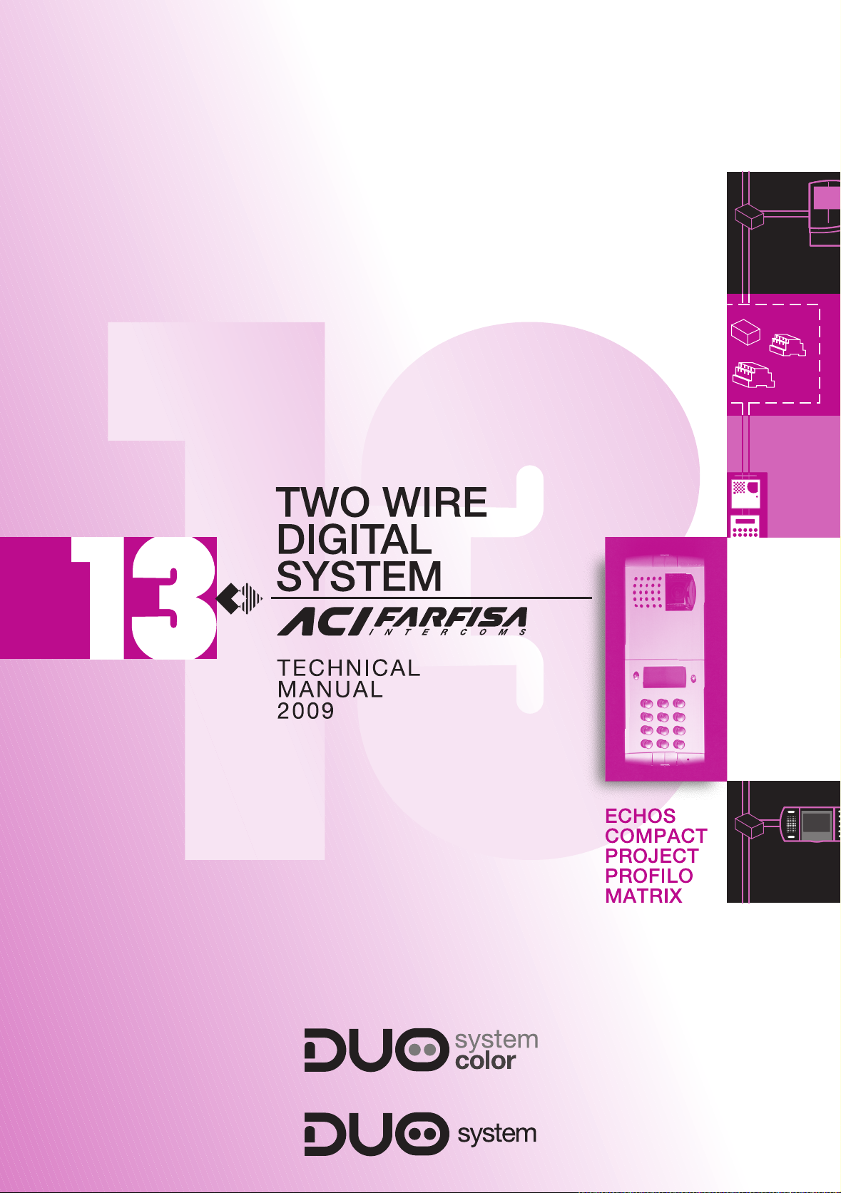
13
TECHNICAL MANUAL
2009 edition
Page
INDEX
Main features
Internal stations
- intercom Compact series
- intercom Project series
- video intercom Echos series
- video intercom Compact series
- video intercom Project series
Door stations
- push-button panel Profilo series
- push-button panel Matrix series
Power supplies
Service modules
- exchanger
- actuator
Installation notes
- main features
- cross section tables
- video signal amplification
Installation diagrams
- Si 51VM/36 One-way videointercom system
- Si 51VM/37 Two-way videointercom system
- Si 51CM/1 Multi-way intercom system connected to one door station
- Si 51VM/1 Multi-way system connected to one audio-video door station
- Si 51VM/12 Multi-way system connected to one audio-video door station and division in two risers
- Si 51VM/32 Multi-way installation connected to one audio-video external door station, additional surveillance camera
and activation of automatic gate by means of actuator
- Si 51VM/35 Multi-way installation connected to one audio-video external door station with video amplifier to increase
installation distance and division in two risers
- Si 52VM/6 Multi-way system connected to two audio-video door stations
- Si 52VM/7 Multi-way system connected to two audio-video door stations and division in two risers
- Si 53VM/1 Multi-way system connected to three audio-video door stations
- Si 56VM/1 Multi-way system connected to one audio-video main common station and division in two risers, each riser
with one audio-video secondary door station
- Si 56VM/2 Multi-way system connected to one audio-video main common door station and division in four risers, each
riser with one audio-video secondary door station
- Si 56VM/11 Multi-way installation connected to one audio-video main common external door station with activation of
automatic gate and division in two risers, with one riser with one audio-video secondary external door station
(staircase division)
- Si 57VM/1 Multi-way system connected to two audio-video main common door stations and division in two risers, each
riser with one audio-video secondary door station
- Si 57VM/2 Multi-way system connected to three audio-video main common door stations and division in two risers,
each riser with one audio-video secondary door station
- application diagrams
(staircase division)
(staircase division)
(staircase division)
(staircase division)
1
2
3
3
7
12
22
27
32
32
53
70
71
72
75
80
80
81
85
88
89
89
91
93
95
97
99
101
103
105
107
109
111
113
115
116
Product list
120
1
(MT13 - Gb2009)
MAIN FEATURES
Farfisa digital DUO System, developed with innovative technology,
allows the installation of videointercom systems up to 200 users and 20
door stations, drawing two non-polarized wires only, including the
power supply to the system. The very reduced number of conductors
with no coaxial cable allows a fast and simple videointercom and/or
intercom installation, reducing mounting costs.
The 2-wire technology allows a videointercom system, with 1 or more
entrances, without having to think to the calculation of the conductors on
the riser and on the various branches; the wires are always two.
For a good result of the installation it is necessary to follow carefully the
indications in this manual and especially it is requested not to exceed
the distances recommended by ACI Farfisa.
Choosing the equipment
The following options are available for door stations:
• door stations with digital push-buttons panels series Matrix or
Profilo
• door stations with conventional push-button panels and digital encoder series Matrix or Profilo
The internal stations can indifferently be videointercoms or intercoms:
• Hands free colour Echos videointercoms with integrated decoder.
• Compact or Project videointercoms with black and white flat CRT
or with color LCD and decoding incorporated.
• Compact or Project intercoms with integrated decoder.
Performances of DUO installations
• Maximum number of risers 4
• Maximum number of videointercoms for each riser 50
• Maximum number of external main door stations 8
• Maximum number of external secondary door stations 12
• Maximum distance between external station and farthest
videointercom (without amplifier) 200 meters (150 meters in the
color version)
• Digital or conventional push-button panels with digital encoder
• Call from landing or intercommunicating is differentiated from the
outdoor one
• Timed conversation (90-second duration with possibility of increasing conversation time by pressing a specific button on the pushbutton panel)
• Acoustic signal of conversation end
• Private audio-video and lock function (only the called user can see,
talk and release lock)
• Coded lock release directly from the digital push-button panel (by
means of programmable personal code)
• Busy signal on door stations
• Free tone on internal stations when the installation is available for
intercommunicating calls or video auto switching
• Connection up to 6 internal stations in parallel and intercommunicating for each user
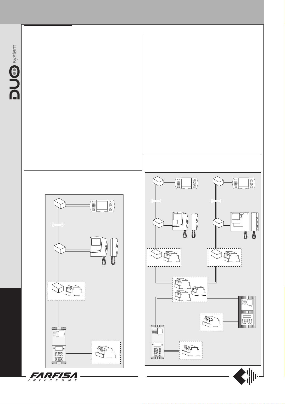
Installation example of a multi-family system with two digital
video door stations and two risers
Installation examples
Installation example of a multi-family system with digital video
door station
2
(MT13 - Gb2009)
INTERNAL STATIONS
INTERCOM WITH INTEGRATED CODING
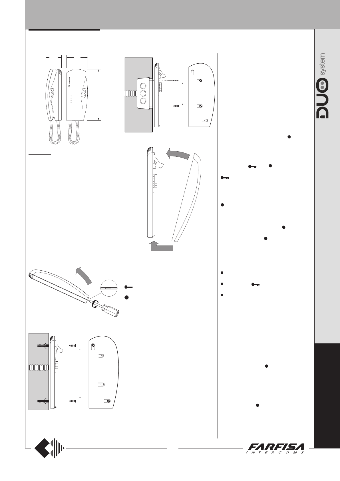
65
9
"
/
2
16
86
3
"
/
3
8
211
5
"
/
8
16
KM862W. White colour intercom with inte-
grated coding, two push-buttons and spiral
cord. Wall-mountable with expansion plugs or
wall box.
Technical characteristics
Power supply directly from the line
Stand-by current: 5mA
Operating current: 0.1A
Operating temperature: 0° ÷ +50°C
Maximum admissible humidity: 90% RH
Terminals
LM/LM Line inputs
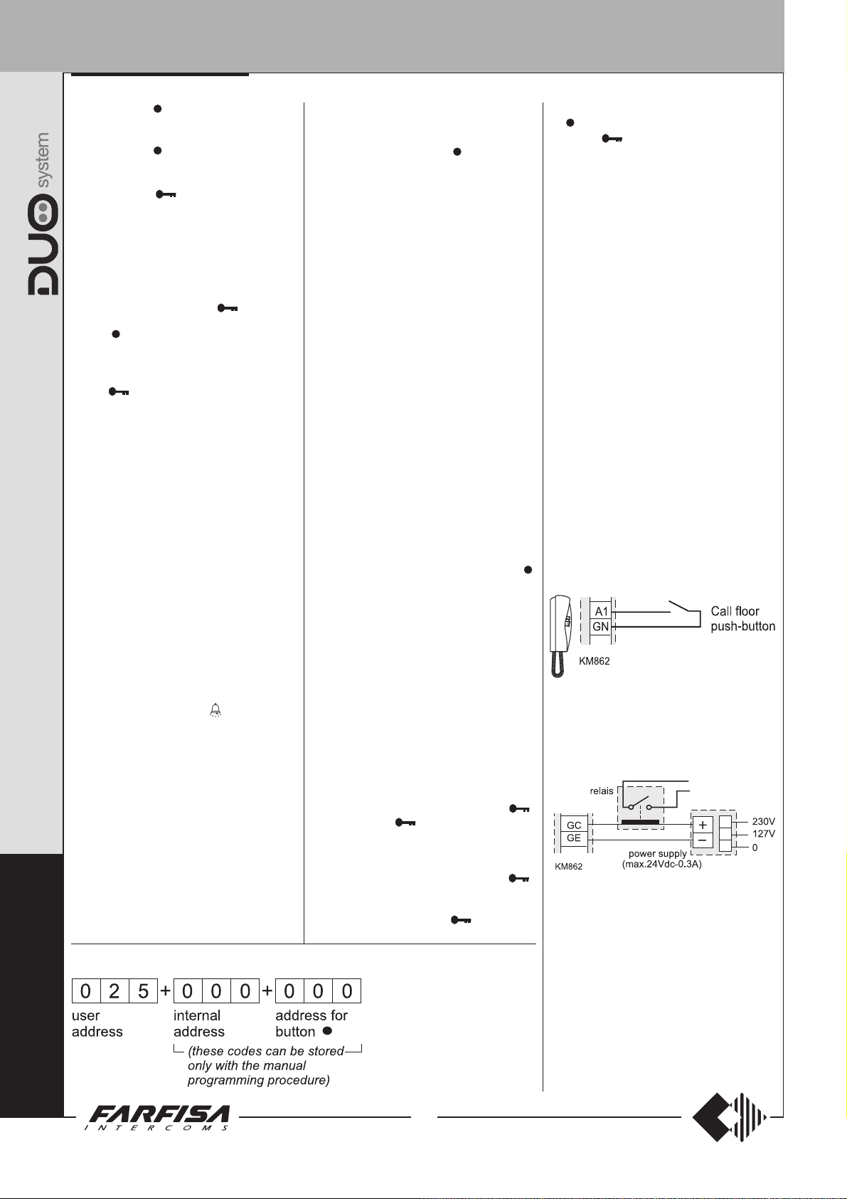
A1 Floor call positive input
GN Floor call negative input
GC Positive output for additional functions
GE Negative output for additional functions
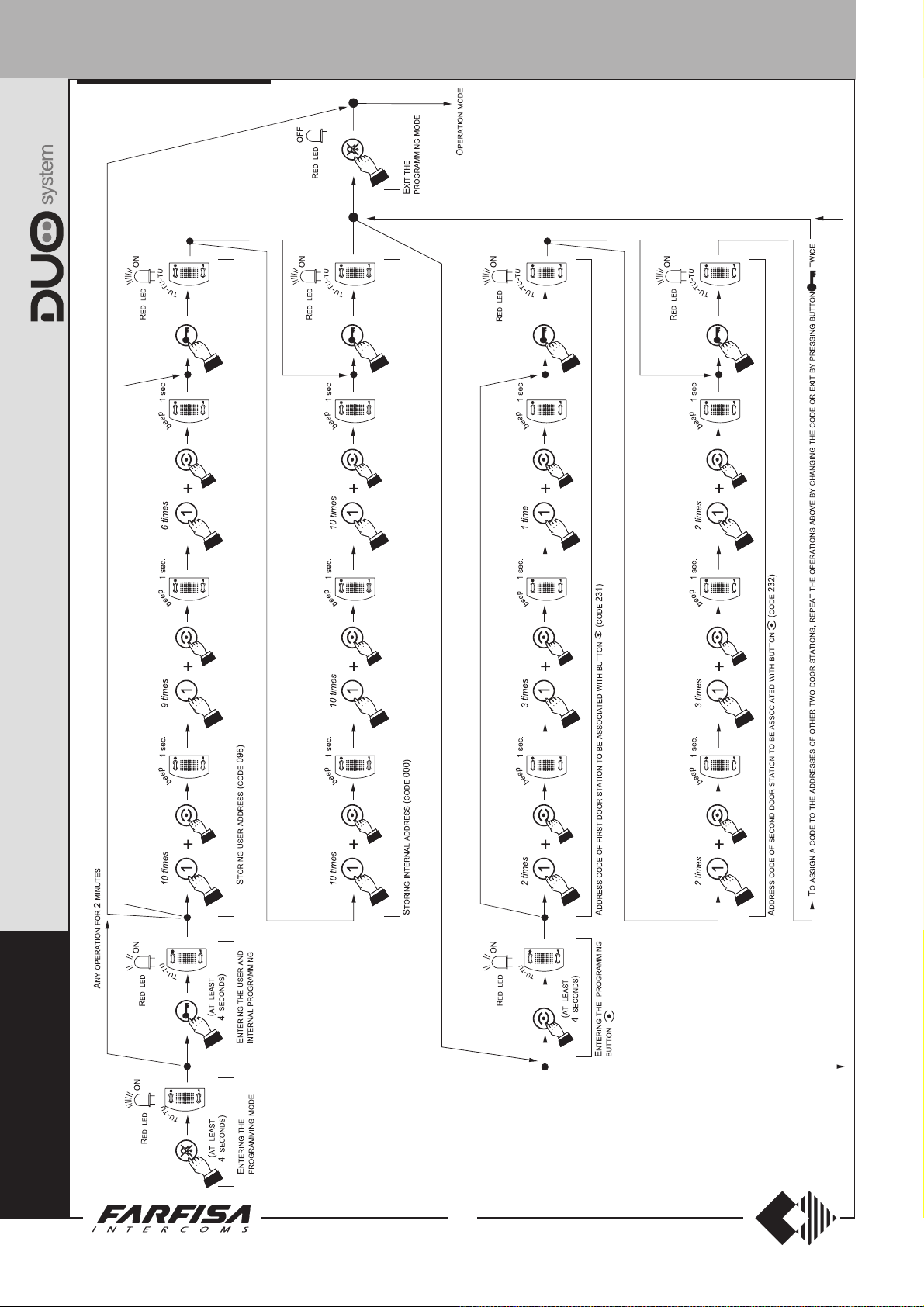
Programming
The intercom must be suitably programmed for
operation.
Two programming modes are available:
-automatic (quick programming of user code
83
1
"
/
3
4
acting from external station);
-manual (programming of all intercom
functions)
The following programming is possible:
1) user address (mandatory: the intercom is
programmed with address 100 by default);
2) internal address (optional: the intercom is
programmed with address 000 by default);
3) code to assign to button “
” to make
intercom calls or for enable actuators (optional:
no code is associated to the button by default).
Using the push-button for programming
Press button " " and " " to enter addresses
or codes.
:Press this button to access the
programming mode (when pressed for
4 seconds with off-hook handset), confirm
address or code programming or go
to the next programming step.
: Press this button to increase the value
you want to enter. Press the button for a
number of times equal to the digit you want
to enter (digit 1 = 1 time; digit 9 = 9 times;
digit 0 = 10 times button “
Pressure of button “
” is confirmed by an
acoustic tone.
”).
160
6
Entering the programming mode
To enter the programming mode you must:
Push-buttons
Door open button
Button for internal or intercom calls.
This button can be associated with the
address of one digital actuator, the
pick up the handset and leave it off-hook
during the entire programming step;
press button “ ” for at least 4 seconds until
you receive the confirmation tone;
start programming within 2 minutes,
otherwise the intercom returns to the
“operation”
mode.
address another user in the building to
make internal calls between two users or
with code 000 to make intercom calls with
other videointercoms or intercoms
(maximum others 2) installed in the
apartment.
Entering codes or addresses
- Codes and/or addresses must have three
digits (hundreds, tens, units); codes and/or
addresses with tens and units or units only
must be completed by adding zeros. For
example, address 96 will become 096 and
address 5 will become 005.
- Digits must be entered individually, by
pressing the button “
5
"
/
16
“n”, where “n” is the value of the digit you want
to enter, followed by a pause of about 2
” for a number of times
seconds before you go to the next digit (a
C
O
M
tone in the handset will tell you when to go to
the next digit).
For example, to enter code 096 you must:
- press button “
” 10 times to enter digit 0,
wait for 2 seconds until you hear a sound in
P
A
the handset;
C
3
(MT13 - Gb2009)
T
INTERNAL STATIONS
- press button “ ” 9 times to enter digit 9, wait
for 2 seconds until you hear a sound in the
handset;
- press button “
for 2 seconds until you hear a sound in the
handset;
- press button “
go to the next programming step. An acoustic
tone in the handset will confirm that the code
has been stored and you can go to the next
step.
” 6 times to enter digit 6, wait
” to confirm entering and
Exiting the programming mode
You will automatically exit the programming
mode after pressing button "
the 3rd programming, i.e. “code to assign to
button “
mode at any time by hanging up the handset.
Settings will not be saved if you exit the
programming mode without confirming with
button "
You will also exit the programming mode
automatically if you make a mistake or an
operation that is not permitted when entering a
code. In this case, you must access the
programming mode again to continue.
”. You can also exit the programming
".
Automatic programming
You can use the automatic programming mode
to save the intercom address from the external
station.
Automatic programming procedure
To enter the automatic programming mode you
must:
a) enter the programming mode following
the instructions described in “
programming mode
b) make a call from an external station
within 2 minutes. In case of installations
with digital push-button keyboard TD2100,
key in the number you want to assign to the
intercom and press “
installations with digital encoder
CD2131÷CD2138 press the button you want
to assign to the user on the push-button
keyboard. When the call is received, the
intercom is programmed automatically, you
hear the call tone in the handset. Close and
pick up the handset to start a conversation
with the external station and check the
correct operation of the system;
c) at the end of the conversation hang up
the handset to exit the automatic
programming mode.
”;
C
O
" to confirm
Entering the
”. In case of
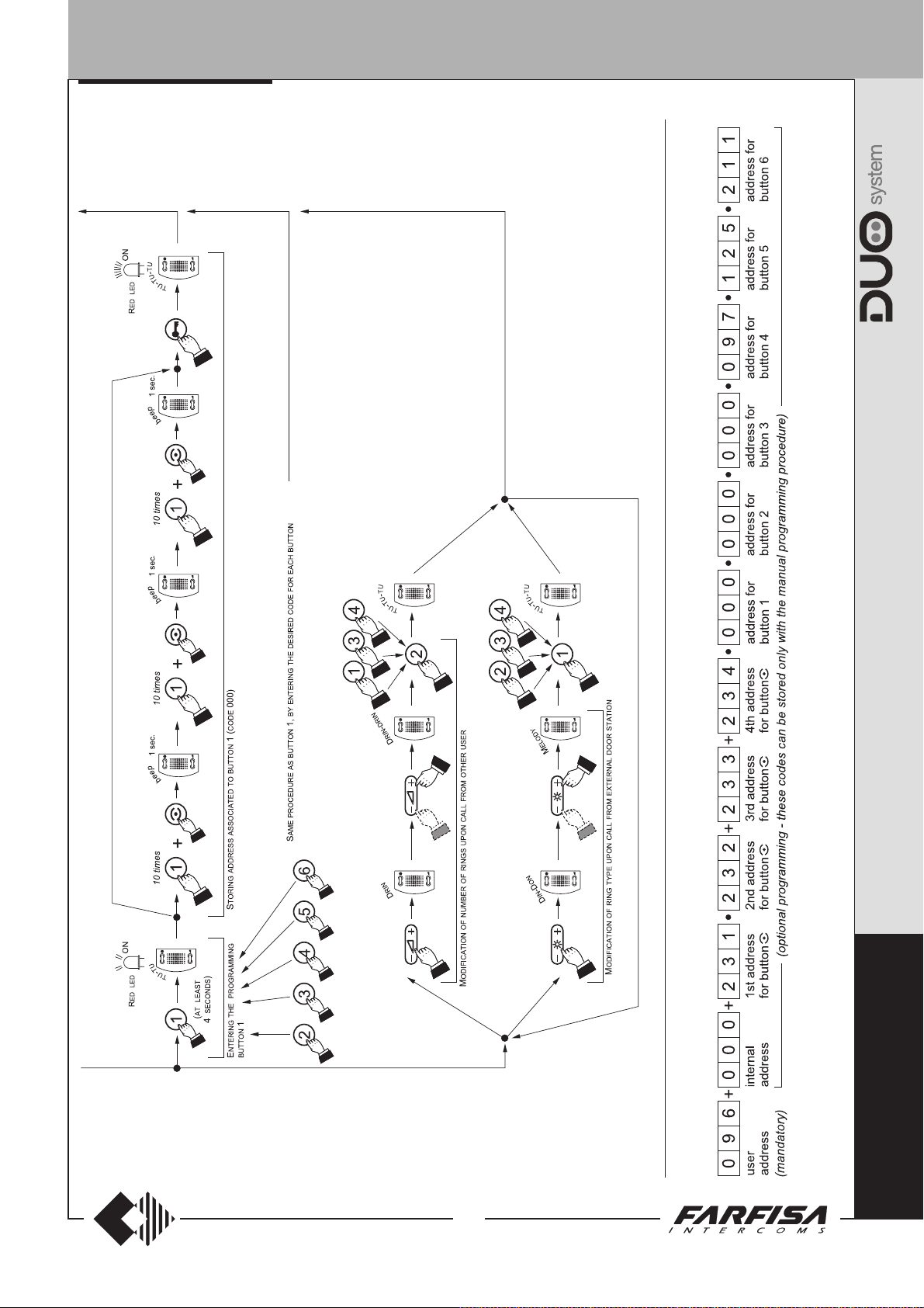
Manual programming
The manual programming mode allows you to
enter the user address, assign the internal
address and code to button “
Manual programming procedure
To enter the manual programming mode you
must:
a) enter the programming mode following
the instructions described in “
programming mode
b) program the following functions in
sequence:
1) User address – this code allows you to
receive an external call, have a
conversation and open the door at the
calling external station. For information
on address entering see “Entering
codes or address”.
2) Internal address – these codes are
used to identify the intercoms installed in
the apartment (max. 3). In case of one
intercom only, the internal code must be
000 (default value); if other intercoms are
present (max. others 2) you must assign
codes 001 and 002 to them. By entering
these codes, all intercoms will ring when
an intercom call is made; if you prefer not
to activate the intercom ring in the third
intercom, you must assign code 003
instead of 002. For information on code
entering see “Entering codes or
addresses”.
3) Address associated with button “
This button can be used for one of the
following functions:
- call to users of other apartments by
entering the user address (from 001 to
200).
- intercom calls between intercoms or
videointercoms in the same apartment
by entering code 000.
- activation of one actuator 2281 (codes
from 211 to 220).
For information on code entering see
“Entering codes or addresses”.
In “Manual Programming” mode the 3
steps above must be performed in
sequence from step 1 to step 3. Each step
must be confirmed by pressing button “
Press button “
a programming operation and go to the next
one. For example, after you have
programmed the “user address (step 1)”
and confirmed it by pressing button “
you will automatically go to the “internal
address (step 2)”. If this setting is not
necessary, press button “
” again if you want to skip
”.
Entering the
”;
” to skip it and
go to “address associated with button
”. Again, you can enter the code or press
button “
there are no other programming to make,
this operation will automatically exit the
programming mode.
c) exit the programming mode following the
instructions described in “
programming mode
General Notes
- Always hang up the handset at the end of
programming for each intercom.
- Repeat the programming steps for all
intercoms in the installation.
- Intercom conversations or connections with
users and external stations of other buildings
will not be possible if digital exchanger
art.2273 is installed.
” to skip this programming. Since
Exiting the
”.
.
Ring volume adjustment
To adjust the ring level you must adjust the
trimmer R52 on the intercom.
Additional functions
Call floor
When you make a call floor, you will hear a
different tone. The floor call is used to inform
that somebody is ringing at the house door. The
function is active both when the system is free
”
and busy.
Call Repeat
You can connect the intercoms as illustrated in
the diagram below to sent the intercom ring to
other locations in the house.
”.
”,
M
Example of manual programming of an intercom
P
A
C
T
4
(MT13 - Gb2009)

012345
012345
012345
012345
012345
012345
012345
INTERNAL STATIONS
Operation
Call from external station.
When a call is made from the external station,
the intercom generates an acoustic tone and
stays on for about 30 seconds. Pick up the
handset to start conversation with the external
station for about 90 seconds and press button
" to open the door.
"
Connection with one or more external
stations without receiving the call.
Picking-up the handset when the system in
stand-by you will hear the tone of system ready.
Press the button “
cation with the door station, from which the last
call has been made; to release the door lock
press again the “
If you pick up the handset and receive no tone,
the installation is busy and you must wait until it
is free.
Making or receiving a call from another
user.
When the installation is in stand-by, you can
make a call to another user. You must have
stored the address of the desired user’s in the
button “
To make the call, pick up the handset, wait for
the free tone and press button “
You will hear the call tone and the intercom of
the called user will ring with a ring different from
calls from external stations or intercom calls
from the same apartment.
If the called user answers within 30 seconds, a
90-second conversation starts, otherwise the
system goes back to free.
The internal conversation in progress will be
automatically interrupted in case of call from
external station to any other user.
If you pick up the handset and receive no tone,
the installation is busy and you must wait until it
is free.
Making or receiving an intercommunicating call in your apartment.
When the installation is in stand-by, you can
make an intercommunicating call to all intercom
in the same apartment (max. 3) by pressing the
button “
000.
To make the intercommunicating call, pick up
the handset, wait for the free tone and press
button “
You will hear the call tone and the intercoms that
are enabled to receive intercommunicating calls
(internal address 001 or 002) will ring with a
ring tone different from calls from external
stations or other users. The intercom will not
ring if it is coded with internal address 003.
However, you can pick up the handset and start
a conversation with the calling user.
If the called user answers within 30 seconds, a
90-second conversation starts, otherwise the
system goes back to free.
The internal conversation in progress will be
automatically interrupted in case of call from
external station to any other user.
”.
” you have programmed with code
”.
” to start a communi-
” button.
”.
Tone table
Tone of pressure of a button.
indicate the pressure of one of the buttons
during the programming phase.
Acknowledge tone.
correct operation of the door lock release and
during the programming phase to indicate a valid
operation.
Tone of system ready.
if the system is free
Calling tone.
user or during an intercommunicating call (active
for 30 seconds or until the called user answers).
Dissuasion tone.
nonexistent device is call or when a device is not
available.
End conversation tone.
before the conversation time ends.
It is activated to confirm the
It is activated during a call to another
It is activated when a
It is activated to
and
Activated for 30 seconds
It is activated 10 seconds
Calling table
External call
Call from another user (continuous tone)
Intercommunicating call (modulated note)
Floor Call
All the acoustic signalling, with the exception
Note.
of the system ready and calling tone, last after
about 2 seconds.
C
O
M
P
A
C
T
5
(MT13 - Gb2009)
INTERNAL STATIONS
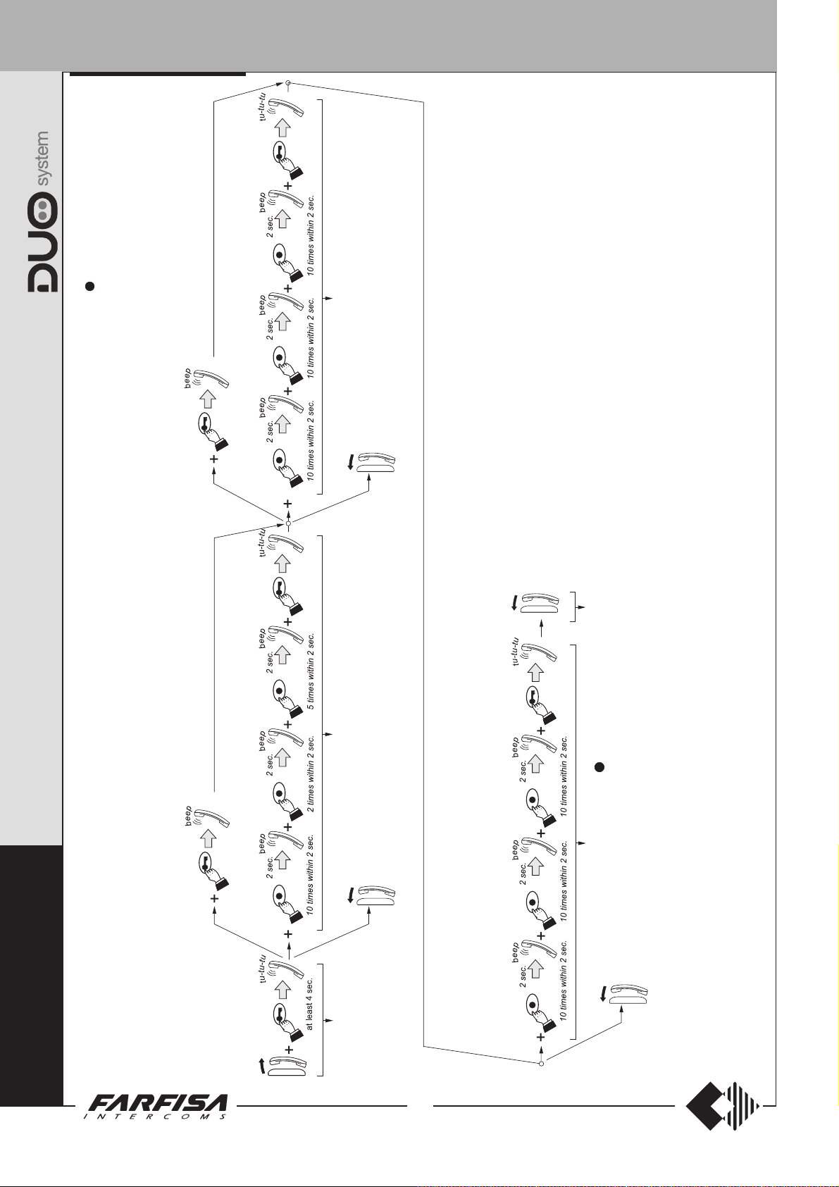
Storing internal address (code 000)Storing user address (code 025)
Exit the programming mode
C
O
M
P
A
C
Exit the programming mode
Exit the programming mode
(code 000)
" "
Storing address associated to button
Exit the programming mode
T
Programming example of a intercom with user address 025, internal address 000 and code 000 associated to button " " to intercommunicate with
other intercoms within the same apartment
Entering the program-
ming mode
6
(MT13 - Gb2009)

INTERNAL STATIONS
INTERCOM WITH INTEGRATED CODING
13
"
/
2
16
8672
3
"
/
3
8
214
1
"
/
8
16
PT562W. White colour intercom with inte-
grated coding, 8 push-buttons and spiral cord.
Wall-mountable with expansion plugs.
Technical characteristics
Power supply directly from the line
Stand-by current: 5mA
Operating current: 0.1A
Operating temperature: 0° ÷ +50°C
Maximum admissible humidity: 90% RH
Terminals
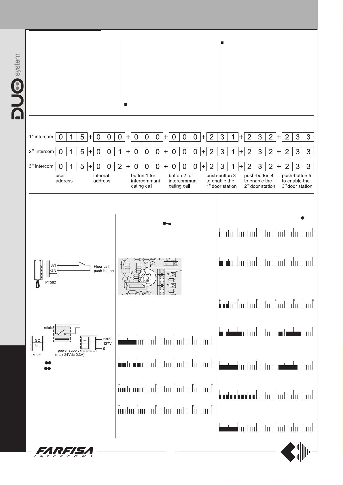
LM/LM Line inputs
A1 Floor call positive input
GN Floor call negative input
GC Positive output for additional functions
GE Negative output for additional functions
P / P Contact of push-button
(max 24Vac/dc 0.3A)
Programming
Intercom must be programmed properly to
define its operating mode. Function that can be
programmed are:
- user address (mandatory programming: the
intercom is programmed with address 100 by
default);
- internal address for intercommunicating calls
(optional programming: the intercom is
programmed with address 000 by default);
- code for supplementary push-buttons
(optional programming: no code is associated
to the buttons by default).
Keypad meaning
To enter addresses or codes you must use the
buttons 1÷5 and the button
the following table.
- To enter numbers from 1 to 5 uses buttons
1÷5.
- To enter numbers from 6 to 0 press the button
(second button from down-up) and then the
corresponding buttons 1÷5 as in the table
(buttons must be pressed one after the other,
not simultaneously).
Intercom buttons cross-reference
figure push-buttons
1= 1
2= 2
3= 3
4= 4
5= 5
6=
7=
8=
9=
0=
Example
to press in sequence:
: to enter the code 028 it is necessary
Enter the programming phase
To enter from the programming phase it is
necessary to do the following steps:
leave the handset on hook and press the
button
- you will hear the programming tone;
lift the handset while holding the button
pressed;
- you will hear the confirmation tone;
leave the handset off hook and release the
button
for at least 4 seconds;
.
Exit the programming phase
Replace the handset on hook to exit the
programming mode.
You will also exit the programming mode if you
make a mistake or an operation that is not
permitted when entering a code.
User address
In order to receive a call from the door station
the intercom must be programmed with an
address witch is stored in a non-volatile memory.
as described in
+1
+2
+3
+4
+5
+5+2+ +3.
To program the intercom it is necessary to:
enter the programming mode following the
instructions contained in “
programming phase
press the button until a programming tone
will be heard;
enter the user address by pressing the buttons
from 1 to 5 and
(see chapter “
table). The code must be included between
001 and 200; three digits must be dialled.
After you have entered the third digit, if the
value is correct, you will hear the confirmation
tone, otherwise you will exist the programming
mode;
continue if you want to program other
functions, otherwise replace the handset on
hook to exit the programming mode.
”;
in the correct sequence
keypad meaning
Enter the
” and relevant
Internal address
In case of multiple intercoms (max. 6) in parallel
in the same apartment, with or without intercommunicating service, the intercoms must be
programmed with codes from 000 and 005.
The main intercom must be programmed with
internal code 000 and the other intercoms with
the following codes (001, 002, 003, 004 and
005).
This programming comes after the user
address programming (see chapter above). If
necessary, programming should be made after
entering the user address and before exiting
the programming mode. If you have already
exited the programming mode, you must repeat
the operations described in the “user address”
chapter and then:
enter the internal identification code (value
from 000 to 005) and press the buttons from
n the correct sequence (to enter 0 you
1 to 5 i
must press
be dialled. After you have entered the third
digit, if the value is correct, you will hear the
confirmation tone, otherwise you will exit the
programming mode;
continue if you want to program other
functions, otherwise replace the handset on
hook.
and then 5); three digits must
Codes assigned to buttons
To use the intercom buttons for calls to other
users, intercommunicating calls or connection
with 1 or more external door stations, you must
program the buttons as described below:
enter the programming mode following the
instructions contained in chapter “
programming phase
hold the button you want to program (1÷5)
pressed until you hear the programming tone;
enter the code you want to assign to the
button (code 000 for calls to intercoms with
intercommunicating call in the same
apartment; codes from 001 to 200 for calls
to users of other apartments; codes from
231 to 250 for connection with one or more
external door stations; codes from 211 to
220 to activate actuator 2281);
- always enter 000 for calls to an intercom-
municating intercom in the same
”;
Enter the
P
R
O
J
E
C
T
7
(MT13 - Gb2009)
INTERNAL STATIONS
012345
012345
012345
012345
012345
012345
apartment, with the same user address.
After you have entered the third digit, if the
value is correct, you will hear the confirmation
tone. The value of the buttons 1÷5 will
automatically determine the address of the
intercom to call;
to call another user enter the corresponding
-
address (value from 001 to 200 – value set
during the “
the intercom to call).
entered.
digit, if the value is correct, you will hear the
confirmation tone;
Example of programming with 3 intercoms in parallel with intercommunicating function and connection with 3 external door stations
from intercoms
user address
After you have entered the third
” programming of
Three digits must be
Supplementary Functions
Floor call
A floor call will generate a different sound
on the intercom. Floor call will only advise
you that someone is calling from the door of
your apartment. This function is enabled
either with the system free or with the system
busy.
- for connection to an external door station
enter the corresponding address (value from
231 to 250 that was previously programmed
on the external door station). After you have
entered the third digit, if the value is correct,
you will hear the confirmation tone;
- enter the address to activate one digital
actuator (value from 211 to 220 that was
previously programmed on actuator). After
you have entered the third digit, if the value is
correct, you will hear the confirmation tone;
repeat the operations illustrated above for all
the buttons you want to program;
adjustment trimmer.
-Press the button
confirmation tone and adjust the volume. If
necessary, press the button again to repeat the
tone.
-Replace the intercom cover.
- Hang up the handset.
to generate the
replace the handset on hook to exit the
programming mode.
Notes.
- You do not need to program the unused buttons.
- Intercom conversations or connections with
users and external stations of other buildings
will not be possible if digital exchanger art.2273
is installed.
- To delete a code assigned to a button enter
the address 255.
Tone table
Tone of pressure of a button.
indicate the pressure of one of the buttons
during the programming phase.
Programming tone.
system is waiting to be programmed.
It is activated to indicate the
It is activated to
, 1÷5
Call repeater
If you connect the devices according to the
diagram reported below it would be
possible to repeat the calling sound of the
intercom in other rooms of your apartment.
P
Button
Button is a free voltage button and
R
contacts are P and P on the terminal board
(max 24Vac-dc/ 0.3A).
O
Ring volume adjustment
J
If it is required to adjust the volume of the
ringing tone it is possible to operate on the
trimmer R12.
E
- Enter the programming mode following
the instructions contained in chapter
C
the programming phase”;
- Remove the intercom cover to access the
T
“Enter
Ring
volume
adjustment
Calling table
External call
012345
Call from another user (continuous tone)
012345
Intercommunicating call (modulated note)
Floor Call
All the acoustic signalling, with the exception
Note.
of the system ready and calling tone, last after
about 2 seconds.
Acknowledge tone.
correct operation of the door lock release and
during the programming phase to indicate a valid
operation and for ring volume adjustment.
Tone of system ready.
if the system is free.
Calling tone.
user or during an intercommunicating call (active for
30 seconds or until the called user answers).
Dissuasion tone.
device is call or when a device is not available.
End conversation tone.
before the conversation time ends.
It is activated to confirm the
Activated for 30 seconds
It is activated during a call to another
It is activated when a nonexistent
It is activated 10 seconds
8
(MT13 - Gb2009)

INTERNAL STATIONS
Example of programming with 3 intercoms with intercommunicating function in the same apartment
(user code 015)
intercoms 1 2 3
Exit the pro-
gramming mode
Exit the program-
ming mode
Exit the program-
ming mode
Storing address associated to button "1" (code 000)
Exit the program-
ming mode
storing internal address (code 000)
storing internal address (code 001)
Storing address associated to button "2" (code 000)
P
storing internal address (code 002)
R
Hold pressed
Exit the pro-
gramming mode
Entering the programming mode Storing user address (code 015)
(MT13 - Gb2009)
9
intercom -
st
1
intercom -
nd
2
intercom -
rd
3
O
J
E
C
T
INTERNAL STATIONS
Operation
Call from external station.
When a call is made from the external station,
the intercom generates an acoustic tone and
stays on for about 30 seconds. Pick up the
handset to start conversation with the external
station for about 90 seconds and press button
" to open the door.
"
Connection with one or more external
stations without receiving the call.
Picking-up the handset when the system in
stand-by you will hear the tone of system ready.
Pressing the
the external door station or the last calling
external station if more than one door stations
are present on the system: in this case, if the
buttons 1÷5 on the intercom have been
programmed with the address of the external
stations, it would be possible to connect
selectivity with them by pressing the related
buttons and, if necessary, to operate the opening
of the relative electric door lock pressing the
button
If picking up the handset you did not get any
tone, the system is busy (a conversation is in
progress with other user), and no other
operations are allowed until the system become
free.
Make or receive a call from another user
When the system is in stand by mode it would be
possible call another user.
To execute this operation it is necessary to have
properly programmed the buttons 1÷5 with the
address of the user you want to call (max 5).
To make the call it is necessary to pick up the
handset, verify the presence of the tone of system
ready and press the button corresponding to the
user you want to call; a calling tone is heard
whilst the intercom of the called user will ring
with a different sound with respect to that of the
external or intercommunicating call.
If the called user lifts the handset within 30
seconds a connection will be set for about 90
seconds, otherwise the system returns in stand
by mode.
Any call from the external door station will interrupt
the internal call.
If picking up the handset you did not get any
tone, the system is busy, and no other operations
are allowed until the system become free.
button you will be connected with
.
P
Make or receive an intercommunicating call in
own apartment.
When the system is in stand by mode it would be
possible call another device installed in the same
apartment (max 6). To execute this operation it is
necessary to have properly programmed the buttons
1÷5 with the code 000 (refer to “
”).
buttons
By pressing one button from 1 to 5, the
intercommunicating intercom is automatically set
by the system and cannot be modified (see table
below).
To make the call it is necessary to pick up the
handset, verify for the presence of the system ready
tone and press the button corresponding to the
device you want to call (see table below). On the
handset of the called user a ring is heard with a
different sound with respect to that of the external or
intercommunicating call.
If the called device answers within 30 seconds a
connection will be set for about 90 seconds,
otherwise the system returns in stand by mode.
Any call from the external door station will interrupt
the intercommunicating call.
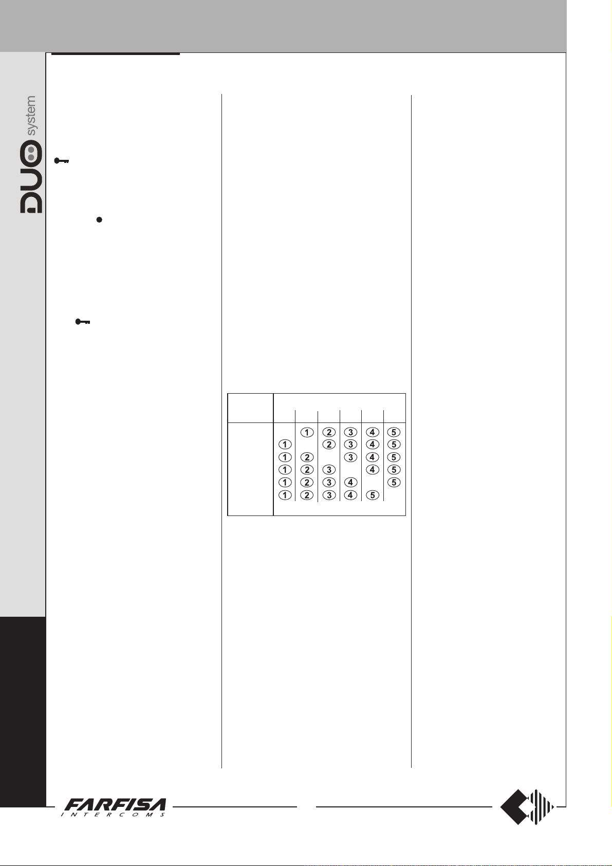
Table on button use for intercom calls of max.
6 intercoms in the same apartment.
Calling Intercom to call
intercoms CT0 CT1 CT2 CT3 CT4 CT5
(000)
CT0
CT1
(001)
CT2
(002)
CT3
(003)
CT4
(004)
CT5
(005)
N.B.:
The codes in parenthesis in the table are the
identification addresses of the internal stations that
were programmed previously (see chapter
address”
Examples:
- From intercom CT1
the button 1 for calls to intercom CT0.
- From intercom CT2
the button 4 for calls to intercom CT4.
- From intercom CT4
the button 2 for calls to intercom CT1.
-
-
Buttons to press
).
(internal address 001)
(internal address 002)
(internal address 004)
codes assigned to
-
-
-
-
“internal
press
press
press
Making an intercommunicating call in
the same apartment or to another
apartment.
If programmed correctly, the buttons 1-5
can be used to make mixed calls; some of
the buttons can be used to call the
intercommunicating intercoms in the same
apartment, some other buttons can be
used to call users in other apartments,
and the remaining buttons can be used to
connect with other external door stations,
if included in the installation.
The buttons with lower numbers should be
used for calls to the intercommunicating
intercoms in the same apartment,
because the system automatically assigns
the address of the intercommunicating
intercom that can be called with each
button according to the table above.
If there are only three intercommunicating
intercoms in the same apartment, they
should be programmed with internal
addresses “000”, “001” and “002” and the
first two buttons 1 and 2 should be used to
make calls; the buttons 3, 4 and 5 can be
used for other functions (see the example
on the next page).
R
O
J
E
C
T
10
(MT13 - Gb2009)
INTERNAL STATIONS
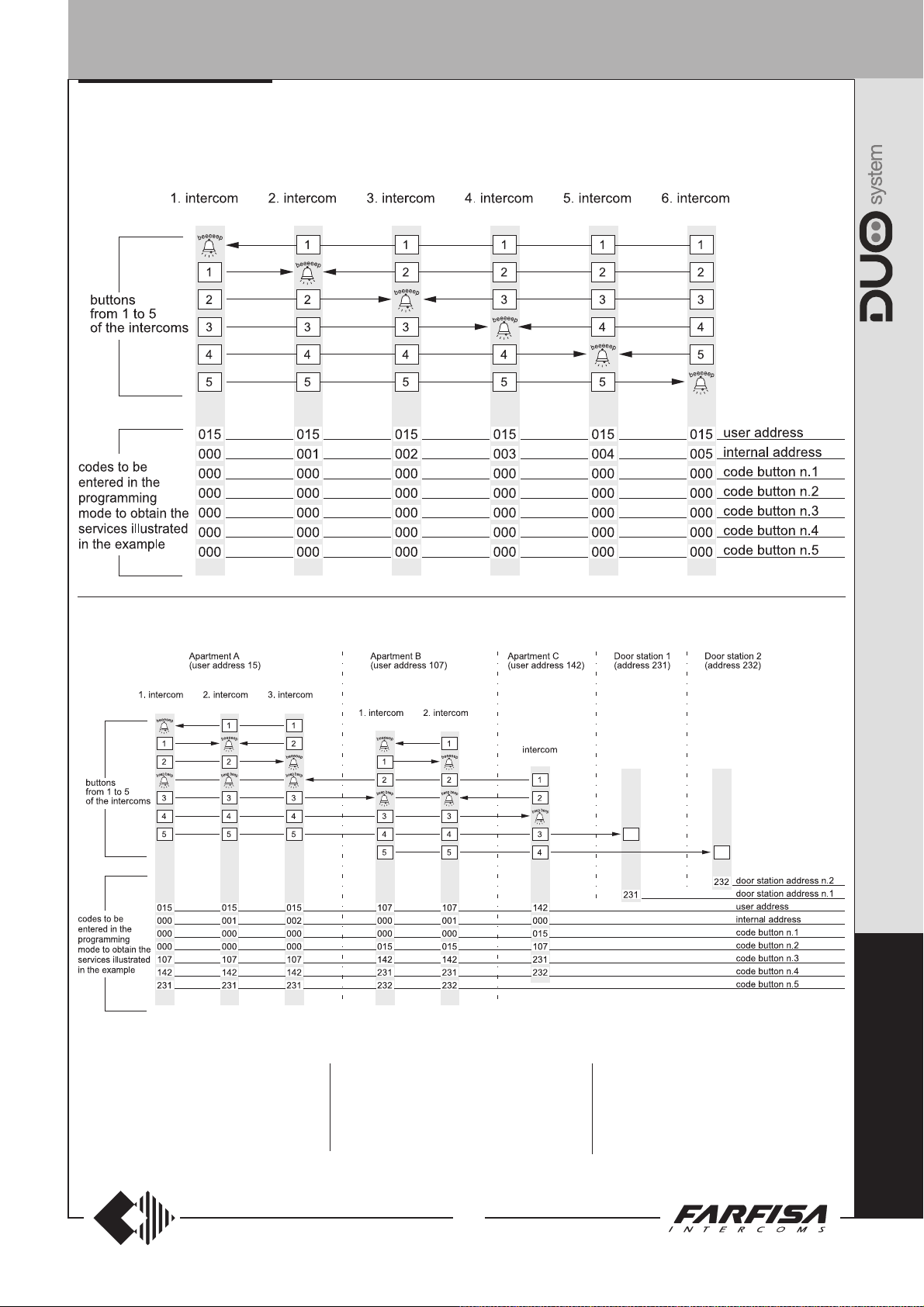
Example of operation for buttons P1 ÷ P5 of intercoms with programming
a) Apartment with 6 intercommunicating intercoms and address user 15
b) Three apartments (A, B and C) with intercommunicating function and possibility to enable two external door stations from
the internal station
Button management
Apartment A (3 parallel intercoms)
Buttons 1 and 2: internal intercommunicating
calls
Button 3: call apartment B (107)
Button 4: call apartment C (142)
Button 5: enable external door station 1
Apartment B (2 parallel intercoms)
Button 1: internal intercommunicating calls
Button 2: call apartment A (15)
Button 3: call apartment C (142)
Button 4: enable external door station 1
Button 5: enable external door station 2
Apartment C (1 intercom)
Button 1: call apartment A (15)
Button 2: call apartment B (107)
Button 3: enable external door station 1
Button 4: enable external door station 2
Button 5: not used
P
R
O
J
E
C
11
(MT13 - Gb2009)
T
INTERNAL STATIONS
VIDEOINTERCOMS WITH INTEGRATED DECODER
16
5
”
/
8
103
1
/
4
208
8
3
”
/
16
1
26
”
EH9262CT. Hands Free Colour Video Intercom with audio-
video privacy, 4 types of calls, 14 differentiated programmable ring
tones, audio, contrast, and brightness adjustment. Metallized grey
colour. Complete with 10 keys for turn-on test function, door lock
opening, intercom calls and miscellaneous services. It can be
installed on the wall by using the back box art.9083 or wall adaptor
WA9100T.
EH9262CW. Hands-free videointercom with same features as
above, in white colour finish. It can be installed on the wall by using
the back box art.9083 or wall adaptor WA9100W.
Installation
”
16
Technical characteristics
Power supply directly from the line
Stand-by current: 7mA
Operating current: 0.4A
Screen: 3.5" LCD
Television standard: PAL
Horizontal frequency: 15625Hz
Vertical frequency: 50Hz
Band width: >5MHz
Starting up time: 1 second
Number of bell rings: 1÷4 (programmable)
Number of programmable bells: 14
Operating temperature: 0° ÷ +50°C
Maximum admissible humidity: 90%RH
Terminals
LM/LM Line inputs
A1 Floor call positive input
GN Floor call negative input
GC Positive output for additional functions
GE Negative output for additional functions
E
C
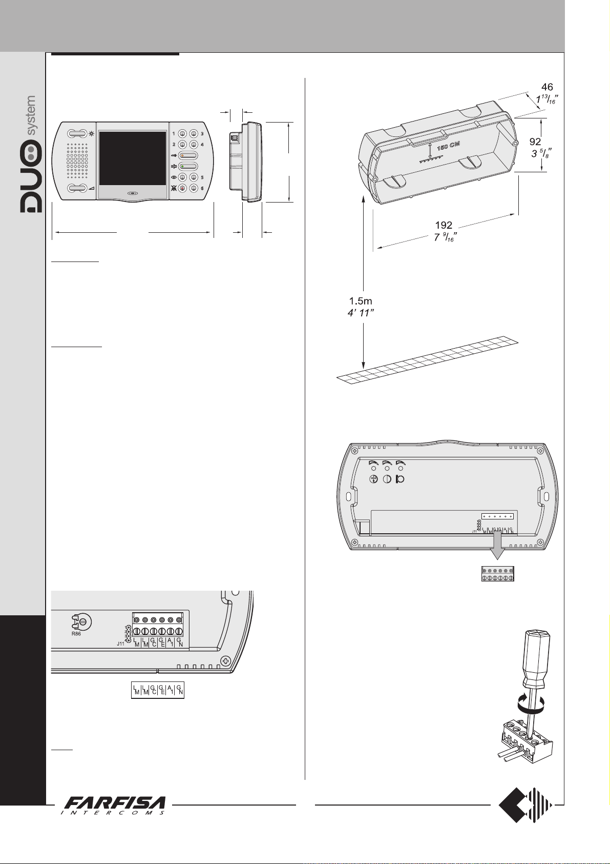
1 - Wall-up the back box art.9083 at an height of about 1.5 meters
above the floor.
2 - Unplug the terminal block from the video intercom.
H
O
9083. Back-box for video intercoms EH9262CT and EH9262CW.
S
3 - Make the connections as required by the
electric diagram to wire.
12
(MT13 - Gb2009)
INTERNAL STATIONS
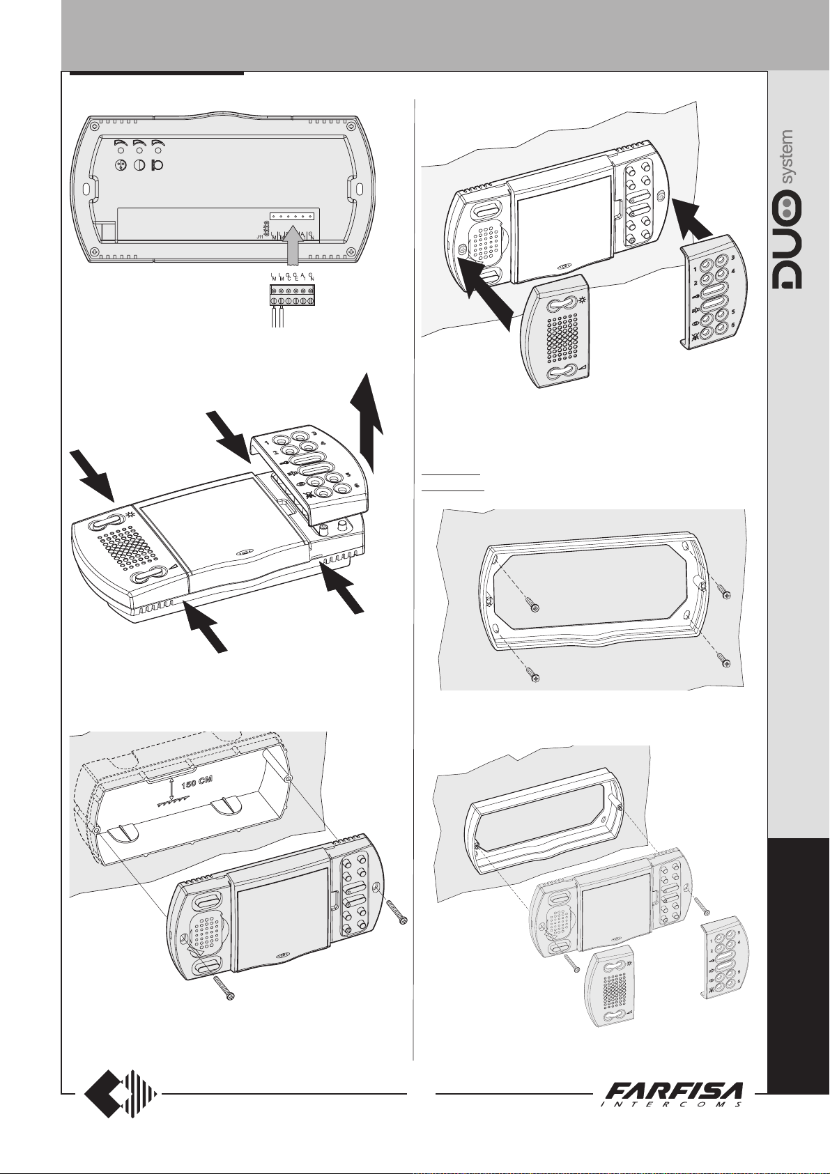
4 - Plug-in back the terminal block on the videointercom.
7 - Re-insert the two frontal plastic frames to the video intercom.
5 - Remove the two frontal plastic frames to approach the two fixing
points of the video intercom.
WA9100T. Wall adaptor for the EH9262CT videointercom.
WA9100W. Wall adaptor for the EH9262CW videointercom.
1 - Fix the adapter to the wall with 4 expansion plugs at approx. 1.5m
from the floor.
6 - Fix the video intercom to the back box using the two screws
supplied with the product.
(MT13 - Gb2009)
6 - Fix the video intercom to the wall adaptor using the two screws
supplied with the product.
13
E
C
H
O
S
INTERNAL STATIONS
E
C
H
O
S
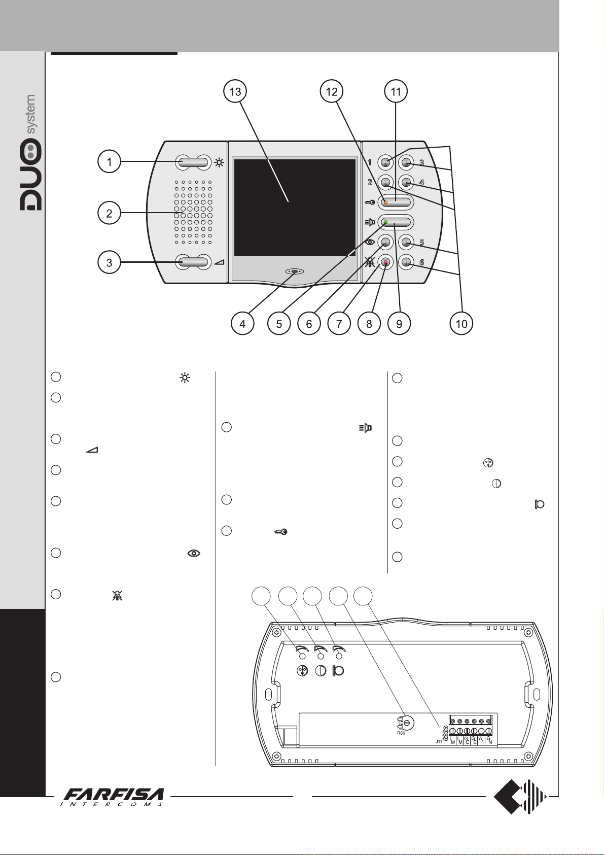
Characteristics
1
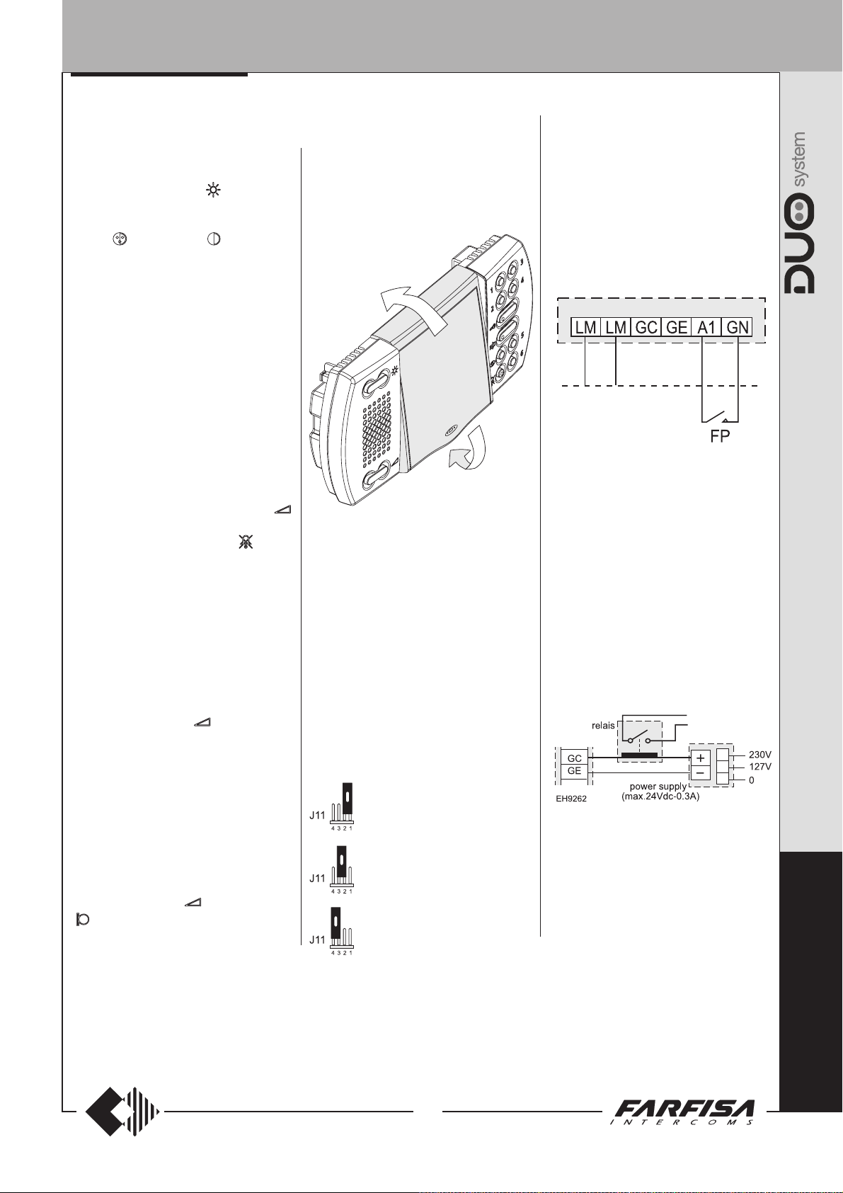
Image brightness adjustment .
2
Loudspeaker. It allows to hear the conversation and to receive the calls from the
external door station or from floor.
3
Call and communication volume adjust-
ment
4
Microphone. It allows to talk with the door
station.
5
Green LED. The LED shows:
- a communication in progress when it
lights up continuously;
- an incoming call when flashing.
6
Control switching ON button . It
allows to power ON the video intercom
and monitoring the entrance.
7
Mute button . It allows to:
- enable/disable the audio (microphone)
to the door station during a conversation;
- enable/disable the bell rings if pressed
for less then 4 seconds;
- enter in the programming mode if
pressed for more than 4 seconds.
8
Red LED. The LED shows:
- temporary disabling of audio when it
continuously lights-up. If audio is enabled again the LED recover the previous
operating mode;
- bell rings disabling when the LED slowly
flashes;
- the videointercom is in the select programming operation mode when the LED
.
it is continuously lit-up;
- the videointercom is in the programming
operation mode when the LED quickly
flashes.
9
Audio communication button . It
allows to enable the audio communication with the door station. The audio
communication is end pressing again the
button or if the communication time expires.
10
Buttons 1, 2, 3,4,5 and 6 are available for
supplementary services.
11
Door lock button. It allows to actuate
the electric door lock with the
videointercom ON.
14 15 16 1817
12
Orange LED. Signalling for “main door
left open” or other services. To achieve
this feature it is necessary to have on the
installation one or more actuators art.
2281 properly connected.
13
3.5" Colour LCD Display.
14
Colour adjustment .
15
Contrast adjustment .
16
Microphone volume adjustment .
17
Microphone sensitivity adjustment
(R86).
18
Jumpers to select the matching impedance of the video signal
(J11).
14
(MT13 - Gb2009)
INTERNAL STATIONS
ADJUSTMENTS
Brightness adjustment.
With the videointercom switched ON, press
left and right the button
brightness of the image.
Colour
The trimmers are located on the back of the
videointercom and can be operated by means
of a small screwdriver.
To adjust the trimmers is required:
- dismount the videointercom from the wall to
accede to the adjustment points;
- power ON the videointercom;
- insert the screwdriver in the hole marked
with the symbol of the adjustment required;
- rotate the screwdriver clock or anti-clock
wise to find the desired image quality;
- fix again the video intercom to the wall.
Enabling, disabling and level of the ringing
sound.
When the videointercom is switched-OFF, it
is possible to adjust the level of the ringing
sound pressing left and right the button
To disable the ringing sound it is necessary
to press momentarily the button
LED flashes during the call and the
conversation.
The status (enabled or disabled) and the level
of the ringing sound are stored and they are
used for next calls.
Setting of the audio level
- During a conversation with the external
door station or with an other intercommunicating video door phone it would be possible
to adjust the loudspeaker’s volume pressing
to one side the button
level is automatically stored and used for
next conversations.
- If the communication the audio is intermittent
or distorted it is advisable to adjust the
microphone sensitivity by acting on the
trimmer
videointercom.
- In case of incorrect automatic switching of
the videointercom between talk and listening
function decrease the level of the preferred
function and increase the other one by
acting on the button
and Contrast adjustment.
R86 located on the back of the
of the videointercom.
to adjust the
; the red
; selected audio
or on the trimmer
Display adjustment
To optimize the angle of view of the display it
can be adjusted up and down for about 15°.
E
C
H
O
S
.
Selecting the closing impedance
Echos videointercoms are provided on the
back with a jumper
correct position, readjusts the signal coming
from the riser to ensure the correct operation of
the connected systems.
J11 Jumper to select impedance termi-
nation line
J11 that, when set in the
1-2 open line
2-3 termination 15
3-4 termination 100
ΩΩ
Ω
ΩΩ
Ω Ω
Ω
Ω Ω
(default)
Additional functions
Call floor
To receive a floor call you must connect a
button (FP) between terminals A1 and GN of
the videointercom.
When the button FP is pressed, the
videointercom speaker will receive a call
different from calls from the external stations.
The call is received also if the videointercom
is in conversation.
Open door signal or other functions
To have a “main door left open” signalling or
other similar services it is necessary to
connect on the installation an actuator art.2281
(see page 75).
When the contact is closed orange LED
lights-ON if the actuator has been correctly
programmed.
Call repeater
Connecting equipments as shown in the
following diagram, it is possible to repeat the
call in other places of the apartment.
E
C
15
(MT13 - Gb2009)
H
O
S

INTERNAL STATIONS
PROGRAMMING
The videointercom must be suitably
programmed for operation.
Two programming modes are available:
-automatic (quick programming of user code
acting from external station);
-manual (programming of all videointercom
functions)
The following programming is possible:
- user address;
- internal address;
- address to assign to button “
4 addresses of external door stations;
- code to assign to buttons “ 1”, “2”, “3”, “4”,
"5" and "6" to make intercom calls, door
station monitoring or for special services;
- call timing (max 4 rings) for 4 different call
melodies (
- selection of the call melody for 4 different
call melodies (
Factory setting
- user address = 100
- internal address = 000
- buttons “
codes are stored to the buttons
- number of call rings and call melody (
table 1
Table 1.
Factory setting for calls
Calls of rings melody
from door station 1 Din-Don
intercommunicating 4 Dring 1
from other users 4 Dring 2
floor (local) 1 Dring 3
Attention: it is mandatory to program the
equipment only with the user code (address) all
other programming are optional.
see table 1
”, “1”, “2”, “3”, “4”, "5", "6" = no
)
);
see table 1
).
Number Type of
Enter the programming mode
Keep pressed the button for more than 4
seconds; an acknowledge tone will be shortly
heard while red LED will lights-ON for all
programming phase. If for 2 minutes no keys
are pressed, system switches back to the
operating mode.
E
Automatic programming
C
You can use the automatic programming mode
to save the videointercom address from the
external station. To enter the automatic
H
programming mode you must:
enter the programming mode following the
O
S
instructions described in “
programming mode
keep pressed the button for more than
4 seconds; red LED starts flashing;
make a call from an external station within
”;
”; maximum
see
Enter the
2 minutes. In case of installations with
digital push-button keyboard TD2100, key
in the number you want to assign to the
videointercom and press “
installations with digital encoder
CD2131÷CD2138 press the button you
want to assign to the user on the pushbutton keyboard. When the call is received,
the videointercom is programmed
automatically, you hear the call tone in the
loudspeaker and the videointercom is turned
on, showing the calling external station.
Press the button
with the external door station and verify the
correct working mode of the equipment;
programming mode is signalled on the
external door station by an acknowledge
tone if accepted or a dissuasion tone if
rejected;
repeat programming phases for all the
videointercoms connected to the system.
to start the conversation
”. In case of
Manual programming
The manual programming mode allows you to
enter the user address, assign the internal
address and codes to numerical buttons
(from 1 to 6) and "
Using the push-buttons for programming
Press button "
addresses or codes.
:Press this button to confirm address or
code programming or go to the next
programming step.
: Press this button to confirm the digit
just dialled and to proceed to enter next
digit in the following order: hundreds
, tens + , units + .
+
1 : Press this button to increase the value
you want to enter. Press the button for
a number of times equal to the digit you
want to enter (digit 1 = 1 time; digit 9 =
9 times; digit 0 = 10 times button “1”).
Entering codes or addresses
- Codes and/or addresses must have three
digits (hundreds, tens, units); codes and/or
addresses with tens and units or units only
must be completed by adding zeros. For
example, address 96 will become 096 and
address 5 will become 005.
- Digits must be entered individually (beginning
from the hundred), by pressing the button
“1” for a number of times “n”, where “n” is
the value of the digit you want to enter. Store
the digit pressing the button "
confirm the acquisition of the 1
- Follow the same procedure to store the 2nd
and 3rd digit.
For example
- press button “1” 10 times to enter digit 0 and
press the button “
the loudspeaker;
- press button “1” 9 times to enter digit 9 and
press the button “
the loudspeaker;
".
", " " and "1" to enter
"; a tone will
st
digit.
, to enter code 096 you must:
”; you will get a tone on
”; you will get a tone on
16
(MT13 - Gb2009)
- press button “1” 6 times to enter digit 6 and
press the button “
the loudspeaker.
Programming of the user address and
internal address
- User address – this code allows you to
receive an external call, turn on the
videointercom, have a conversation and
open the door at the calling external station.
- Internal address – these codes are used
to identify the videointercoms installed in
the apartment (max. 7). In case of one
videointercom only, the internal code must
be 000 (default value); if other videointercoms are present (max. other 6) you must
assign to them the codes 001, 002, 003
etc. Programming these addresses all the
videointercoms will ring-UP when receiving
an external, intercommunicating or floor
(local) call
To program the user address and internal
address it is necessary to:
enter the programming mode following
the instructions described in “
programming mode
keep pressed the button for more
than 4 seconds; red LED starts flashing;
enter the 3 digit of the user address
following the procedure reported on the
paragraph “Entering codes or
addresses”;
press the button to confirm the
present phase and move to the next
phase which is: programming of the
internal address; an acknowledge tone
will be heard;
enter the 3 digit of the internal address
following the procedure reported on the
paragraph “Entering codes or
addresses”;
press the button to confirm; an
acknowledge tone will be heard and the
red LED lights-ON continuously;
proceed with another programming phase
or exit the programming mode pressing
button
Note. If one of the two above mentioned
addresses is already correctly programmed
and you don’t want to program it again it
would be possible to skip its programming
by simply pressing button
Programming address to be stored to
each button
Button “
addresses of maximum 4 external stations
which can be connected sequentially. In
this way the user can monitor, communicate
or open the door of 4 different external
stations without being called from them but
simply pressing several times the button
In the case of a system with only 1
external door station it isn’t necessary
”. To this button can be stored the
”; you will get a tone on
(
if programmed - see page 18)
Enter the
”;
or .
.
.
.

INTERNAL STATIONS
to store any address because it will be
acquired automatically at the first call.
To make the programming it necessary to:
enter the programming mode following
the instructions described in “
programming mode
keep pressed the button " " for more
than 4 seconds; red LED starts flashing;
enter the 3 digit of the address of the 1st
external door station to be stored
(codes from 231 to 250) following the
procedure reported on the paragraph
“Entering codes or addresses” ;
press the button to confirm the
present address move to the 2nd one; an
acknowledge tone will be heard;
enter the 3 digit of the address of the 2nd
external door station and confirm by
pressing button
proceed entering the addresses of the
3rd and 4th external stations (if present)
or exit the present programming phase
pressing several times the button
you will be led back to selecting programming mode;
proceed with another programming or
exit programming mode by pressing
button
Note: store only the addresses of the
external door stations to which the
user can be connected. Don’t store the
addresses of external door stations
belonging to different buildings even if
in the same installation.
Buttons 1,2,3,4,5 and 6.
These buttons can be used to:
make intercommunicating calls;
- to call users of different apartments it is
necessary to store in each button of
your monitor the address of the user you
wish to call pressing that button (codes
from 001 to 200).
- to call other videointercoms installed in
the same apartment (local intercommunicating service), it is necessary to
store in the buttons 1,2,3,4,5,6 of each
monitor always the code 000; start from
button 1 and go on until you have
programmed, with the code 000, as
many buttons as are the videointercoms
installed in the apartment (max 6 units)
or .
”;
;
Enter the
you wish to call; automatically by pressing
buttons 1,2,3,4,5 of one unit you will call the
unit whose internal address is related to the
pressed button according to table 2.
Table 2.
Addresses for intercommunicating calls
Internal Button to press
address 1 2 3 4 5 6
000 001 002 003 004 005 006
001 000 002 003 004 005 006
002 000 001 003 004 005 006
003 000 001 002 004 005 006
004 000 001 002 003 005 006
005 000 001 002 003 004 006
006 000 001 002 003 004 005
For example if you press the button 3 from the
videointercom whose intercommunicating
address is 002 you will call the intercommu-
nicating user 003.
monitoring external door stations (it is
,
suggested to use button
external door station) to enable this feature
store the address of the external door station
(codes from 231 to 250).
optional functions operated by means of
the actuators art.2281; to enable this
functions store the address of the actuator
to be operated (codes from 211 to 220).
To make the programming it is necessary:
enter the programming mode following
the instructions described in “
programming mode
a - keep pressed for more than 4 seconds
the button you wish to program; red LED
starts flashing;
b -enter the 3 digit of the code of the desired
function following the procedure reported
on the paragraph “Entering codes or
addresses”;
c -press the button ; an acknowledge
tone will be heard and the red LED lightsON continuously;
repeat phases a-b-c to program the other
buttons or exit the programming mode press-
ing button
Notes.
- In each button can be stored only one code.
- Intercom conversations or connections with
users and external stations of other buildings
or ; red LED turns-OFF.
to monitor the 1
Enter the
”;
will not be possible if digital exchanger art.2273
is installed.
Programming the number of ringing call
enter the programming mode following
the instructions described in “
programming mode
a - press button ; only one ring will be
heard;
b - to press left and right the button to
respectively increase or decrease the number of rings. After each pressure of the
button the selected number of rings will be
heard;
c - press one of the buttons (1,2,3 or 4) to
select the type of call you wish to change
(
see table 3
if it’s required to modify the number of
ringing call of another type of call, repeat
points a-b-c;
proceed with other programming phases or
exit the programming mode pressing the
button
Programming a melody for a call type
st
enter the programming mode following
the instructions described in “
programming mode”
a - press the button ; the melody actually
programmed will be heard;
b - to push laterally (left or right side) the
button to select the previous or next ringer
tone;
c - press one of the button 1,2, 3 or 4 to select
the type of call to modify (
if it is required to modify the melody of
another type of call, repeat the points a-b-c;
exit the programming mode pressing the
button
Table 3.
Buttons to programming the type of call
Button Type of c all
1 from external door station
2 from other users
3 intercommunicating
4 floor (local)
or ; red LED turns-OFF.
or ; red LED turns-OFF.
”;
);
;
Enter the
Enter the
see table 3
Exit the programming phase
In any situation it is possible to exit the
programming mode by pressing the button
or .
);
E
Example of automatic programming of a user address (code 111)
17
(MT13 - Gb2009)
C
H
O
S

INTERNAL STATIONS
More programming operations for specific functions
How to program secondary addresses
additional programming operation that does
(
not depend on the programming operations
of user and internal station addresses)
The following programming operation allows
you to save 4 additional user addresses on the
same videointercom (i.e.: exchanger function,
videointercom installed in common area with
multiple users, etc.)
To make the programming it is necessary:
enter the programming mode following
the instructions described in “
programming mode
keep pressed the button “ ” (right side) for
more than 4 seconds; red LED starts flashing;
enter the 3 digit of the 1st user address
(codes from 1 to 200) following the procedure
reported on the paragraph “Entering codes
or addresses”;
press the button to confirm the present
address and move to the 2nd user address;
an acknowledge tone will be heard;
enter the 3 digit of the 2nd user address
and confirm by pressing button
proceed entering the 3rd and 4th address
consumer (if necessary) or to press twice the
button “
common inside address;
”;
” to pass to the insertion of the
Enter the
;
enter the 3 digit that compose the inside
address common to the 4 new user
addresses (codes from 000 to 007) following
the procedure of the paragraph “Entering
codes or addresses”.
Note:
the internal address has to be unique
and different from you address him inside
eventually programmed on other videointercoms and/or intercoms that has the same
user address;
to press “ ” to confirm and to return of
choice of programming; an acknowledge
tone will be heard and the red LED lights-ON
continuously;
proceed with another programming or exit
programming mode by pressing button
or .
Note
: If you want to make intercom calls, you
must program the call buttons with the codes of
the users you want to call.
Examples
Programming of three videointercoms (VC101,
VC102 and VC103), with one intercom with
reception of all three external calls (VC103).
a)
programming with direct switch-on of
videointercoms upon their own call.
Videointercom 103 will receive all calls, but
will switch on only upon its own call.
VC101. User address = 101; internal address
= 000
VC102. User address = 102; internal address
= 000
VC103. User address = 103; internal address
= 000; programming secondary addresses
=101
b)
programming with direct switch-on of
videointercom 103 only upon any call. The
other two videointercoms will receive the
call, but will stay off. Press the button
switch them on. In this case the intercom
service is not possible.
VC101. User address = 101; internal address
= 001
VC102. User address = 102; internal address
= 001
VC103. User address = 103; internal address
= 000; programming secondary addresses
=101
102 001
to
102 000
System programming
The following programming allows you to
personalise the operation mode of button “
used to deactivate the ring tones and the GC-
GE terminals and send the floor call to the
systems with the same user address (internal
stations in parallel). See table 4.
To make the programming it is necessary:
enter the programming mode following
the instructions described in “
programming mode
Table 4 - Table of system programming codes
Programming Function description Default Value entered with buttons
code value
bit 0 send floor call to other internal stations in parallel
E
C
H
O
S
bit 1 button
bit 2 button deactivates all ring tones and button tones
bit 3 button does not deactivate ring tones and button tones
bit 4 reserved NO NO -
bit 5 the GC-GE terminals are activated upon call from external door station
bit 6 the GC-GE terminals are activated upon intercom call
bit 7 reserved NO NO -
(1)
From the internal station connected to the floor call button FP and with programming value 1 for bit 0 the floor call is also sent to the other systems
in parallel.
(2)
If bits 1, 2 and 3 are programmed with value 0 (NO), press the button , without a conversation in progress, to deactivate the external and
intercom ring tones.
(3)
If bits 5 and 6 are programmed with value 0 (NO), the GC and GE terminals are activated to send the calls.
”;
deactivates all ring tones
Enter the
keep pressed the button “ ” (right side)
”
for more than 4 seconds; red LED starts
flashing;
press the key “ ” and/or “1” eight times
according to the desired programming;
press “ ” to confirm and return to programming selection; you will hear the confirmation tone and the red LED will turn on and
stay on;
proceed with another programming or exit
programming mode by pressing button
(1)
(2)
(2)
(2)
(3)
(3)
or .
Example
To activate the function illustrated in table 4 for
bits 0 and 2 and deactivate it for the other bits,
press the following buttons in a sequence:
1 .
1
= 0 1 = 1
NO NO YES
NO NO YES
NO NO YES
NO NO YES
NO NO YES
NO NO YES
18
(MT13 - Gb2009)

INTERNAL STATIONS
012345
012345
012345
012345
012345
OPERATION
Call from the door station
When a call is made from the external station,
the videointercom speaker receives the rings
(according to programming), the green LED
starts flashing and the calling user is displayed
on the screen for around 30 seconds. Also
the red LED flashes if the ring has been
deactivated. If the call time has expired and
the videointercom has turned OFF, press the
button "
" to reconnect with the calling
external station.
To start the conversation with the external
station for once of around 90 seconds, press
button; the green LED goes ON.
the
If it is desired to disable the audio to the door
station, but continuing hearing the audio
from the door station press shortly the button
; in this status the red LED will light up
continuously. To restore the audio to the door
station press again the button
; the red
LED will recover the previous status.
In case of a call to a user with more than one
videointercom in parallel installed in the apartment, all the videointercom will ring, but only
the videointercom with internal address 000
will turn ON. You can answer from this
videointercom by following the instructions
above. From others videointercoms it is
possible to answer by pressing button
This operation will automatically turn ON this
videointercom and will turn OFF the intercom
that had been turned ON before. If, before
answering, you wish display who is ringing,
press the button
and then the button .
To operate the electric door lock release
press the button
.
To end the communication and switch OFF
the video intercom press the button
; the
green LED goes OFF.
The video intercom switches OFF
automatically when the communication time
expires.
Monitor function and connection with one
or more external stations.
With the system in stand-by and no
conversation in progress, it would be possible
to monitor the external door stations by
pressing on the videointercom the button
or the other buttons previously programmed
for this function.
If the installation includes more external
stations and button "
" is programmed
correctly, you can monitor the external stations
(max. 4) in sequence by pressing the same
button again and again.
The videointercom will be turned ON for
about 30 seconds. The monitoring will be
interrupted in case of request of monitor
service by another user, call between users
or from an external station.
Pressing the button while monitoring,
automatically the communication with the
external door stations is enabled.
If after pressing the button
the monitor
remains switched-OFF and a busy tone is
heard, another conversation is in progress
and it is necessary to wait until the system
becomes free.
Making or receiving a call from another
user.
When the installation is in stand-by, you can
make a call to another user. You must have
stored the address of the desired user’s in
the numerical buttons.
Before making a call press the button
if you get a busy tone, wait until the system
becomes free; if you get a free tone it is
possible to make a call by pressing the
proper button. After pressing the button you
will get a calling tone on the loudspeaker,
while the videointercom of the called user
rings (without switching-ON) with the
programmed melody. If the called user
answers within 30 seconds, a 90-second
conversation starts, otherwise the system
goes back to free.
The internal conversation in progress will be
automatically interrupted in case of call from
external station to any other user.
.
Making or receiving an intercom call in
your apartment.
When the system is in stand-by it would be
possible to make a local intercommunicating
call to all the videointercoms installed in the
apartment (max 7 monitors with internal
address from 000 to 006) by pressing
buttons previously programmed with code
000.
Before making the internal call press the
button
, if you get a busy tone wait until
the system becomes free; if you get a free
tone it is possible to make an internal call by
pressing the proper button. After pressing
the button you will get a calling tone on the
loudspeaker, while the videointercom of the
called user rings (without switching-ON)
with the programmed melody. If the called
user answers within 30 seconds, a 90second conversation starts, otherwise the
system goes back to free.
The internal conversation in progress will be
automatically interrupted in case of call from
external station to any other user.
Tone table
Tone of pressure of a button. It is activated to
indicate the pressure of the buttons.
Monitor function. Activated on monitor function
and confirmation of programming value
Communication. Activated on button
pressure, during the conversation, programming
and attended answer
Activation. Activated on button pressure and
;
numerical buttons if programmed with actuator
address
Programming. It confirms the beginning of the
programming mode
Acknowledge. It is activated during the
programming phase to indicate a valid operation.
System ready. Activated for 30 seconds if the
system is free
Calling. It is activated during a call to another user
or during an intercommunicating call (active for 30
seconds or until the called user answers).
Busy. Activated on pressure of the buttons with
busy line
Dissuasion. It is activated when a non-existent
device is call or when a device is not available
End conversation. It is activated 10 seconds
before the conversation time ends
Note.
All the acoustic signalling, with the exception
of the system ready and calling tone, last after
about 2 seconds.
Calling table
1 DIN-DON
2 DRING1
3 DRING2
4 DRING3
5 DRING4
6 MELODY1
7 MELODY2
8 MELODY3
9 MELODY4
10 MELODY5
11 MELODY6
12 MELODY7
13 MELODY8
14 BEEP
E
C
H
O
S
19
(MT13 - Gb2009)
INTERNAL STATIONS
Example of manual programming of a
videointercom
E
C
H
O
S
20
(MT13 - Gb2009)
INTERNAL STATIONS
21
(MT13 - Gb2009)
E
C
H
O
S
Note. The example refers to an apartment with 4 videointercoms in parallel with intercom service. To allow for the individual intercom call between videointercoms the internal station address must
extensions and activation of actuator for supplementary services.
Example of manual programming of videointercom connected to 4 external door stations, intercom call in own apartment with other 3 videointercoms, intercom call with other 2
be changed in the other 3 videointercoms by entering the following numbers (intercom 2 001, intercom 3 002 and intercom 4 003)
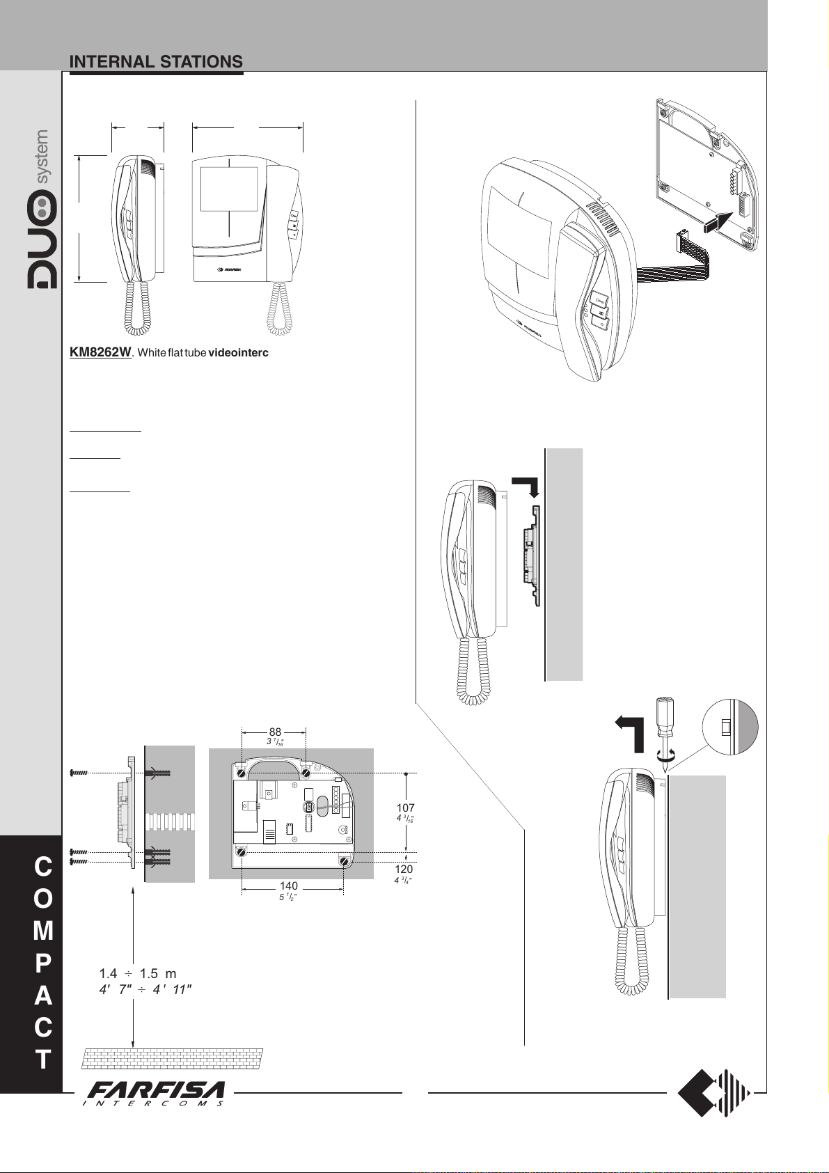
aaaaaaaaaaaaaaaaaaaaaaaaaaaa
aaaaaaaaaaaaaaaaaaaaaaaaaaaa
aaaaaaaaaaaaaaaaaaaaaaaaaaaa
INTERNAL STATIONS
VIDEOINTERCOMS WITH INTEGRATED DECODER
201
7
15
"
/
16
229
9
88
7
"
/
3
16
"
KM8262W. White flat tube videointercom with audio-video privacy,
electronic microphone, modulated electronic ringing sounds, terminal
board for the connection to the wall-bracket and 3 push-buttons for door
lock release, control switch ON and additional functions. It can be
installed on the wall (with no built-in) by using the wall-bracket WB8262..
KM8262CW. Version with 4" colour LCD.
WB8262. The wall bracket for the KM8262W videointercom in-
cludes a terminal board for connection to the system.
WB8262C. The wall bracket for the KM8262CW videointercom.
Technical characteristics
Power supply directly from the line
Stand-by current 6 mA
Operating current 0.6A
Screen 4" FLAT CRT or LCD
Starting up time 2 ÷ 4 sec.
Operating temperature 0° ÷ +50°C
Maximum admissible humidity 90%RH
(KM8262W)
0.4A
(KM8262CW)
Plugging in of videointercom connectors to the terminal boards of wall
bracket.
Installation of videointercom onto the
wall bracket.
Terminals
LM/LM Line inputs
A1 Floor call positive input
GN Floor call negative input
GC Positive output for additional functions
GE Negative output for additional functions
C
O
M
P
A
1.4 1.5 m÷
4" 7" 4" 11"÷
C
88
7
"
3
/
16
140
1
"
/
5
2
Measures for the installation of the wall
bracket WB8262 to the wall, and recommended height from the floor.
107
4
120
3
4
3
"
/
16
"
/
4
Installation of videointercom onto the wall bracket.
T
22
(MT13 - Gb2009)
INTERNAL STATIONS
Buttons
Door open button
Monitor button. This button can be
associated with 4 addresses of external
stations to monitor the entrances. When
you press the button for the first time, the
videointercom connects with the external
station that called last. When you press the
button again, the videointercom connects
in sequence with the external stations
whose addresses have been previously
stored. If the installation has only one
external station, the address does not need
to be stored, since it will be automatically
acquired upon the first call. If the installation
has more than 4 external stations, you
must select the 4 external stations you
want to control. Of course, calls will be
received from all the external stations (also
more than 4) in the installation that are
enabled to calls according to the installation
diagram.
Button for internal or intercom calls.
This button can be associated with the
address of a digital actuator, the address
another user in the building to make internal
calls between two users or with code 000
to make intercom calls with other
videointercoms or intercoms (maximum
others 2) installed in the apartment. The
videointercoms will ring simultaneously if
not otherwise programmed.
Programming
The videointercom must be suitably programmed for operation. Two programming
modes are available:
-automatic (quick programming of user code
acting from external station);
-manual (programming of all videointercom
functions)
The following programming is possible:
1) user address (mandatory: the video-
intercom is programmed with address 100 by
default);
2) internal address (optional: the video-
intercom is programmed with address 000 by
default);
3) address of external station 1 to assign
to button “
to the button by default);
4) address of external station 2 to assign
to button “
to the button by default);
5) address of external station 3 to assign
to button “
to the button by default);
6) address of external station 4 to assign
to button “
to the button by default);
7) code to assign to button “
intercom calls or for enable actuators (optional:
no code is associated to the button by default).
” (optional: no code is associated
” (optional: no code is associated
” (optional: no code is associated
” (optional: no code is associated
” to make
Using the push-button keyboard for
programming
Press button " " and " " to enter addresses
or codes.
:Press this button to access the
programming mode (when pressed for
4 seconds with off-hook handset), confirm
address or code programming or go
to the next programming step.
: Press this button to increase the value
you want to enter. Press the button for a
number of times equal to the digit you want
to enter (digit 1 = 1 time; digit 9 = 9 times;
digit 0 = 10 times button “
Pressure of button “
acoustic tone.
” is confirmed by an
”).
Entering the programming mode
To enter the programming mode you must:
pick up the handset and leave it off-hook
during the entire programming step;
press button “ ” for at least 4 seconds until
you receive the confirmation tone;
start programming within 2 minutes,
otherwise the videointercom returns to the
“operation”
mode.
Entering codes or addresses
- Codes and/or addresses must have three
digits (hundreds, tens, units); codes and/or
addresses with tens and units or units only
must be completed by adding zeros. For
example, address 96 will become 096 and
address 5 will become 005.
- Digits must be entered individually, by
pressing the button “
“n”, where “n” is the value of the digit you want
to enter, followed by a pause of about 2
seconds before you go to the next digit (a
tone in the handset will tell you when to go to
the next digit). For example, to enter code
096 you must:
- press button “
wait for 2 seconds until you hear a sound in
the handset.
- press button “
for 2 seconds until you hear a sound in the
handset.
- press button “
for 2 seconds until you hear a sound in the
handset.
- press button “
go to the next programming step. An acoustic
tone in the handset will confirm that the code
has been stored and you can go to the next
step.
” for a number of times
” 10 times to enter digit 0,
” 9 times to enter digit 9, wait
” 6 times to enter digit 6, wait
” to confirm entering and
Exiting the programming mode
You will automatically exit the programming
mode after pressing button "
the 7th programming, i.e. “
button “
mode at any time by hanging up the handset.
Settings will not be saved if you exit the
programming mode without confirming with
button "
You will also exit the programming mode
automatically if you make a mistake or an
”
. You can also exit the programming
".
" to confirm
code to assign to
operation that is not permitted when entering a
code. In this case, you must access the
programming mode again to continue.
Automatic programming
You can use the automatic programming mode
to save the videointercom address from the
external station.
Automatic programming procedure
To enter the automatic programming mode you
must:
a) enter the programming mode following
the instructions described in “
programming mode
b) make a call from an external station
within 2 minutes. In case of installations
with digital push-button keyboard TD2100,
key in the number you want to assign to the
videointercom and press “
installations with digital encoder
CD2131÷CD2138 press the button you want
to assign to the user on the push-button
keyboard. When the call is received, the
videointercom is programmed automatically, you hear the call tone in the handset
and the videointercom is turned on, showing
the calling external station. Close and pick
up the handset to start a conversation with
the external station and check the correct
operation of the system;
c) at the end of the conversation hang up
the handset to exit the automatic
programming mode.
”;
Entering the
”. In case of
Manual programming
The manual programming mode allows you to
enter the user address, assign the internal
address and codes to buttons "
Manual programming procedure
To enter the manual programming mode you
must:
a) enter the programming mode following
the instructions described in “
programming mode
b) program the following functions in
sequence:
1) User address – this code allows you to
receive an external call, turn on the
videointercom, have a conversation and
open the door at the calling external
station. For information on address
entering see
address”
2) Internal address – these codes are
used to identify the videointercoms
installed in the apartment (max. 3). In
case of one videointercom only, the
internal code must be 000 (default value);
if other videointercoms are present (max.
others 2) you must assign codes 001
and 002 to them. By entering these codes,
all videointercoms will ring when an
intercom call is made; if you prefer not to
activate the intercom ring in the third
videointercom, you must assign code
.
”;
“Entering codes or
" and “ ”.
Entering the
C
O
M
P
A
C
T
23
(MT13 - Gb2009)
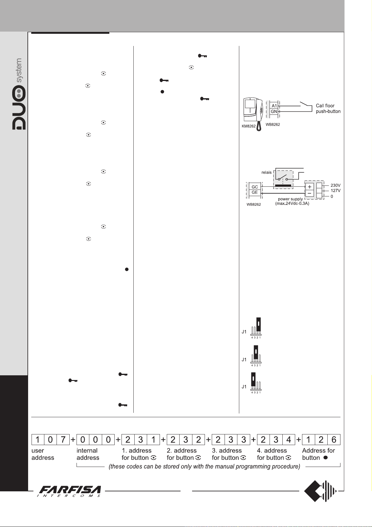
INTERNAL STATIONS
C
O
003 instead of 002. For information on
code entering see “Entering codes or
addresses”.
3) Address of external station 1
associated with button "
of external station 1 you want to connect
with when button "
installation only includes one external
station, the address does not need to be
stored, since it will be automatically
acquired upon the first call.
4) Address of external station 2
associated with button "
of external station 2 you want to connect
with when button "
code does not need to be saved if the
installation does not include two external
stations. For information on code entering
see “Entering codes or addresses”.
5) Address of external station 3
associated with button "
of external station 3 you want to connect
with when button "
code does not need to be saved if the
installation does not include three
external stations. For information on code
entering see “Entering codes or
addresses”.
6) Address of external station 4
associated with button "
of external station 4 you want to connect
with when button "
code does not need to be saved if the
installation does not include four external
stations. For information on code entering
see “Entering codes or addresses”.
7) Address associated with button “
This button can be used for one of the
following functions:
- call to users of other apartments by
entering the user address (from 001 to
200).
- intercom calls between intercoms or
videointercoms in the same apartment
by entering code 000.
- activation of one actuator 2281 (codes
from 211 to 220).
For information on code entering see
“Entering codes or addresses”.
In “Manual Programming” mode the 7
steps above must be performed in
sequence from step 1 to step 7. Each step
must be confirmed by pressing button “
Press button “
a programming operation and go to the next
one. For example, after you have
programmed the “user address (step 1)”
and confirmed it by pressing button “
you will automatically go to the “internal
” again if you want to skip
" – address
" is pressed. If the
" – address
" is pressed. This
" – address
" is pressed. This
" – address
" is pressed. This
address (step 2)”. If this setting is not
necessary, press button “
go to “address of external station 1 to be
assigned to button
can enter the code. Otherwise you can press
button “
6 and go to “address associated with
button
the code or press button “
programming. Since there are no other
programming to make, this operation will
automatically exit the programming mode.
c) exit the programming mode following the
instructions described in “
programming mode
General Notes
- Always hang up the handset at the end of
programming for each videointercom.
- Repeat the programming steps for all
videointercoms in the installation.
- Intercom conversations or connections with
users and external stations of other buildings
will not be possible if digital exchanger
art.2273 is installed.
” 4 times to skip steps 3, 4, 5 and
” (step 7)”. Again, you can enter
.
” to skip it and
(step 3)”. Now you
” to skip this
Exiting the
”.
Ring volume adjustment
To adjust the ring level you must adjust the
trimmer R8 on the wall bracket WB8262.
”
”.
”,
Additional functions
Call floor
When you make a call floor, you will hear a
different tone. The floor call is used to inform
that somebody is ringing at the house door. The
function is active both when the system is free
and busy.
Call Repeat
You can connect the videointercoms as
illustrated in the diagram below to sent the
videointercom ring to other locations in the
house.
Jumper the closing impedance
The wall bracket WB8262C are provided with
the jumper J1 that, when placed in the correct
position, allows to readapt the signal from the
riser for the correct operation of the connected
devices.
J1 Jumper to select impedance video
signal
1-2 open line
2-3 termination 15
3-4 termination 100
ΩΩ
Ω
ΩΩ
Ω Ω
Ω
Ω Ω
(default)
M
To make the programming easier and to remind your self the stored codes, please fill in the following table
P
A
C
T
24
(MT13 - Gb2009)

INTERNAL STATIONS
and code 126 associated
" "
Exit the programming mode
(code 126)
" "
Storing internal address (code 000)Storing user address (code 107)
Exit the programming mode
Exit the programming mode
Storing address associated to button
Exit the programming mode
address of button
th
and 4
rd
, 3
nd
, 2
st
C
O
M
" to intercommunicate with the user 126
No codes associated to the 1
Exit the programming mode
P
A
Programming example of a videointercom with user address 107, internal address 000, no code associated to button
to button "
Entering the programming
mode
25
(MT13 - Gb2009)
C
T
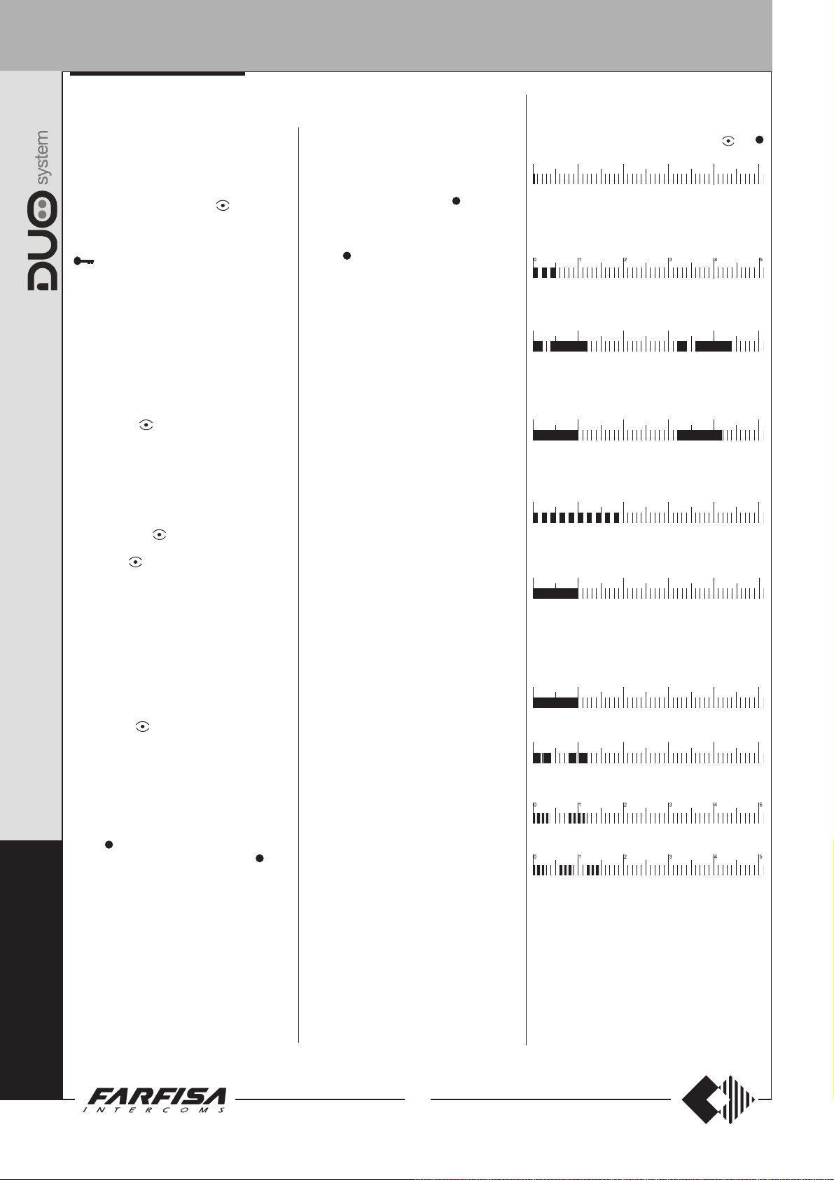
INTERNAL STATIONS
012345
012345
012345
012345
012345
012345
012345
Operation
Call from external station.
When a call is made from the external station,
the videointercom turns on, generates an
acoustic tone and stays on for about 30 seconds.
If the call time has expired and the videointercom
has turned off, press the button "
with the calling external station. Pick up the
handset to start conversation with the external
station for about 90 seconds and press button
" to open the door.
"
In case of a call to a user with more than one
videointercom in parallel installed in the
apartment, all the videointercom will ring, but
only the videointercom with internal address
000 will turn on. You can answer from this
videointercom by following the instructions
above. You can answer from the other
videointercom by picking up the handset. This
operation will automatically turn ON this
videointercom and will turn OFF the
videointercom that had been turned ON before.
Press button "
before answering and then pick up the handset.
Monitor function and connection with one
or more external stations.
When the installation is in stand-by and no
conversation is in progress, you can monitor
the entrance by picking up the handset and
pressing button "
If the installation includes more external stations
and button "
can monitor the external stations (max. 4) in
sequence by pressing the same button again
and again.
The videointercom will be turned ON for about
30 seconds. The monitoring will be interrupted
in case of request of monitor service by another
user, call between users or from an external
station. If you pick up the handset during the
monitoring, you will automatically establish a
voice conversation with the external station.
If the videointercom will not turned ON when you
press button "
busy and you will have to wait until it becomes
free again.
Making or receiving a call from another
user.
When the installation is in stand-by, you can
make a call to another user. You must have
stored the address of the desired user’s in the
button “
wait for the free tone and press button “
will hear the call tone and the videointercom of
C
the called user will ring (without turning on) with
a ring different from calls from external stations
O
or intercom calls from the same apartment. If
the called user answers within 30 seconds, a
90-second conversation starts, otherwise the
M
system goes back to free.
The internal conversation in progress will be
P
automatically interrupted in case of call from
external station to any other user.
A
If you pick up the handset and receive no tone,
the installation is busy and you must wait until it
is free.
C
" if you want to see the caller
".
" is programmed correctly, you
", this means the installation is
”. To make the call, pick up the handset,
" to reconnect
”. You
Making or receiving an intercommunicating call in your apartment.
When the installation is in stand-by, you can
make an intercommunicating call to all
videointercom in the same apartment (max.
3) by pressing the button “
programmed with code 000.
To make the intercommunicating call, pick up
the handset, wait for the free tone and press
button “
videointercoms that are enabled to receive
intercommunicating calls (internal address
001 or 002) will ring (without turning ON) with
a ring tone different from calls from external
stations or other users. The videointercom
will not ring if it is coded with internal address
003. However, you can pick up the handset
and start a conversation with the calling user.
If the called user answers within 30 seconds,
a 90-second conversation starts, otherwise
the system goes back to free.
The internal conversation in progress will be
automatically interrupted in case of call from
external station to any other user.
”. You will hear the call tone and the
” you have
Tone table
Tone of pressure of a button. It is activated to
indicate the pressure of one of the buttons
during the programming phase.
Acknowledge tone. It is activated to confirm the
correct operation of the door lock release and during
the programming phase to indicate a valid operation.
Tone of system ready. Activated for 30 seconds
if the system is free.
Calling tone. It is activated during a call to another
user or during an intercommunicating call (active
for 30 seconds or until the called user answers).
Dissuasion tone. It is activated when a
nonexistent device is call or when a device is not
available.
End conversation tone. It is activated 10 seconds
before the conversation time ends.
and
Calling table
External call
Call from another user (continuous tone)
Intercommunicating call (modulated note)
Floor Call
Note.
All the acoustic signalling, with the exception
of the system ready and calling tone, last after
about 2 seconds.
T
26
(MT13 - Gb2009)
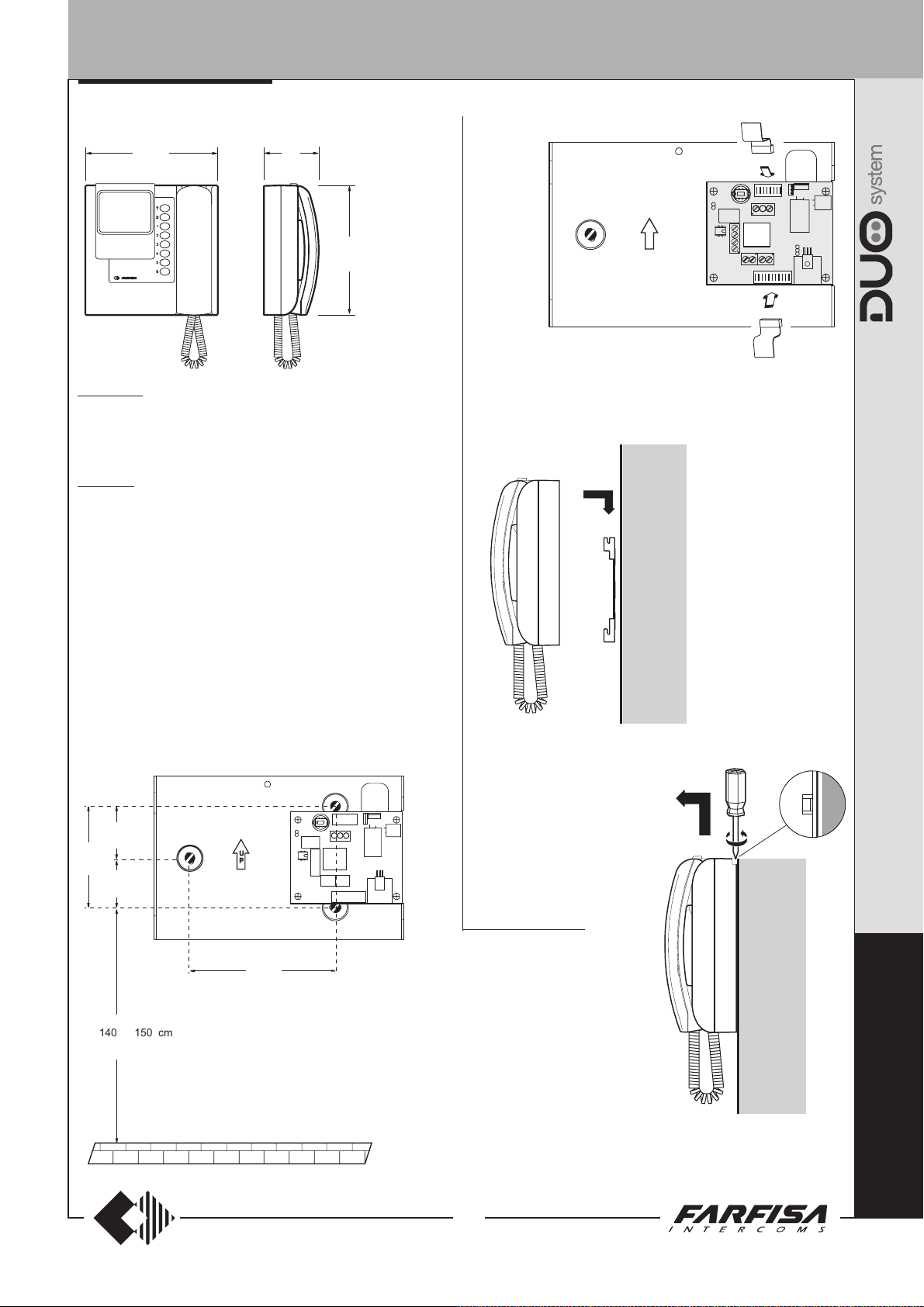
U
P
U
P
INTERNAL STATIONS
VIDEOINTERCOMS WITH INTEGRATED DECODER
215.5
1
/
8
2
"
89
1
"
/
3
2
215
7
"
/
8
16
PT5262W. White flat tube videointercom with audio-video privacy,
electronic microphone, modulated electronic ringing sounds, terminal
board for the connection to the wall-bracket and 7 push-buttons for door
lock release, control switch ON and intercommunicating calls. It can be
installed on the wall (with no built-in) by using the wall-bracket WB5262.
WB5262. The wall bracket for the PT5262W videointercom includes
a terminal board for connection to the system.
Technical characteristics
Power supply directly from the line
Stand-by current 5 mA
Operating current 0.6A
Screen 4" FLAT CRT
Starting up time 2 ÷ 4 sec.
Operating temperature 0° ÷ +50°C
Maximum admissible humidity 90%RH
J1
LM
U
P
GPE GPC
GN
A1
P1
3
J2
A+
P1
A-
2
1
Plugging in of videointercom connectors to the terminal boards of
wall bracket.
Terminals
LM/LM Line inputs
A1 Floor call positive input
GN Floor call negative input
GPC Positive output for additional functions
GPE Negative output for additional functions
P1/P1 Contact of push-button n.6 (max 24Vac/dc 0.3A)
4
122
13
J1
LM
GPE GPC
GN
A1
P1
P1
"
/
16
83.5
3
43
11
"
/
1
16
5
"
/
16
40.5
5
"
/
1
8
U
P
140 150 cm÷
4" 7" 4" 11"÷
Measures for the installation of the
wall bracket WB5262 to the wall, and
recommended height from the floor.
Installation of videointercom onto the wall bracket.
Dismounting of videointercom from the wall bracket.
P
R
O
J
E
C
T
27
(MT13 - Gb2009)

INTERNAL STATIONS
Programming
Videointercom must be programmed properly
to define its operating mode.
Function that can be programmed are:
- user address (mandatory programming: the
videointercom is programmed with address
100 by default);
- internal address for intercommunicating calls
(optional programming: the videointercom is
programmed with address 000 by default);
- code for supplementary push-buttons
(optional programming: no code is associated
to the buttons by default);
- bell volume (two level adjustment; high-low).
Keypad meaning
To enter addresses or codes you must use the
buttons 1÷5 and
table.
- To enter numbers from 1 to 5 uses buttons
1÷5.
- To enter numbers from 6 to 0 press the button
(second button from down-up) and then the
corresponding buttons 1÷5 as in the table
(buttons must be pressed one after the other,
not simultaneously).
Videointercom buttons cross-reference
as described in the following
figure push-buttons
1=1
2=2
3=3
4=4
5=5
6=
7=
8=
9=
0=
Example
it is necessary to press in
sequence:
: to enter the code 028
+5+2+ +3.
Enter the programming phase
To enter from the programming phase it is
necessary to do the following steps:
leave the handset on hook and press the
button
- you will hear the programming tone;
lift the handset while holding the button
P
R
O
J
E
pressed;
- you will hear the confirmation tone;
leave the handset off hook and release the
button
Exit the programming phase
Replace the handset on hook to exit the
programming mode.
You will also exit the programming mode if you
make a mistake or an operation that is not
permitted when entering a code.
for at least 2 seconds;
.
C
T
+1
+2
+3
+4
+5
User address
In order to receive a call from the door station
the videointercom must be programmed with
an address witch is stored in a non-volatile
memory. To save the code you must:
enter the programming mode following the
instructions contained in “
programming phase
press the button until a programming tone
will be heard;
enter the user address by pressing the buttons
from 1 to 5 and
(see chapter “
table). The code must be included between
001 and 200; three digits must be dialled.
After you have entered the third digit, if the
value is correct, you will hear the confirmation
tone, otherwise you will exist the programming
mode;
continue if you want to programme other
functions, otherwise replace the handset on
hook to exit the programming mode.
”;
in the correct sequence
keypad meaning
Enter the
” and relevant
Internal address
In case of multiple videointercoms (max. 6) in
parallel in the same apartment, with or without
intercommunicating service, the videointercoms must be programmed with codes from
000 and 005. The main videointercom must be
programmed with internal code 000 and the
other videointercoms with the following codes
(001, 002, 003, 004 and 005).
This programming comes after the user
address programming (see chapter above). If
necessary, programming should be made after
entering the user address and before exiting
the programming mode. If you have already
exited the programming mode, you must repeat
the operations described in the “
chapter and then:
enter the internal identification code (value
from 000 to 005) and press the buttons from
n the correct sequence (to enter 0 you
1 to 5 i
must press
be dialled. After you have entered the third
digit, if the value is correct, you will hear the
confirmation tone, otherwise you will exit the
programming mode;
continue if you want to programme other
functions, otherwise replace the handset on
hook.
and then 5); three digits must
user address
Codes assigned to buttons
To use the videointercom buttons for calls to
other users, intercommunicating calls, enable
actuators or connection with one or more
external door stations, you must programme
the buttons as described below:
enter the programming mode following the
instructions contained in chapter “
programming phase
hold the button you want to programme (1÷5)
pressed until you hear the programming tone;
enter the code you want to assign to the
button (code 000 for calls to videointercoms
with intercommunicating function in the same
apartment; codes from 001 to 200 for calls
to users of other apartments; codes from
231 to 250 for connection with one or more
”;
Enter the
external door stations; codes from 211 to
220 to activate actuator 2281);
-always enter 000 for calls to an video-
intercom with intercommunicating
function in the same apartment, with the
same user address. After you have entered
the third digit, if the value is correct, you will
hear the confirmation tone. The value of the
buttons 1÷5 will automatically determine the
address of the videointercom to call;
to call another user enter the corresponding
-
address (value from 001 to 200 – value set
during the “
the videointercom to call).
be entered.
digit, if the value is correct, you will hear the
confirmation tone;
-for connection to an external door station
enter the corresponding address (value from
231 to 250 that was previously programmed
on the external door station).
entered the third digit, if the value is correct,
you will hear the confirmation tone;
- enter the address to activate one digital
actuator (value from 211 to 220 that was
previously programmed on actuator). After
you have entered the third digit, if the value is
correct, you will hear the confirmation tone;
repeat the operations illustrated above for all
the buttons you want to programme;
replace the handset on hook to exit the
programming mode.
Notes.
- You do not need to programme the unused
buttons.
- Intercom conversations or connections with
users and external stations of other buildings
will not be possible if digital exchanger
”
art.2273 is installed.
- To delete a code assigned to a button enter
the address 255.
user address
After you have entered the third
” programming of
Three digits must
After you have
Ring volume adjustment
In order to modify the bell level, you have to:
enter the programming mode following the
instructions contained in “
programming phase
press the button to change the level
(from high to low and vice-versa),
The videointercom shall confirm the operation
with a tone which sound level is equal to the
recorded bell level.
”;
Enter the
28
(MT13 - Gb2009)
 Loading...