

Page 1

AB3G
COMUNICARE OVUNQUE
http://farsa.com/qr/mycom-cloud/
Modulo posto esterno 3G ALBA per applicazioni citofoniche
INTRODUZIONE
AB3G è un dispositivo basato su tecnologia 3G progettato
per realizzare sistemi di comunicazione semplici ed adabili.
I dispositivi possono essere utilizzati in molteplici applicazioni
come un sistema citofonico senza li o un sistema di controllo
accessi.
I moduli AB3G supportano 2 ingressi per comandi analogici,
2 uscite a relé, SMS di controllo ed allerta, gestione carte
prepagate, ecc ...
CARATTERISTICHE ED APPLICAZIONI
Caratteristiche
Integra modulo 3G Cinterion (EHS6-A)
Supporta chiamate anche con tasti o tastiera aggiuntiva
2 ingressi analogici utilizzabili anche come funzione allarme
2 relé in uscita
Fino a 200 numeri di telefono per la funzione CLIP
Programmabile da porta USB con il programma "myCom
manager", tramite SMS o attraverso il Cloud Farsa
Congurazione di sistema scaricabile con il programma
"myCom manager", SMS o attraverso il Cloud Farsa
Applicazioni
Impianti citofonici senza li
Apriporta o apricancello remotizzato (funzione CLIP)
Semplici funzioni di allarme
ALBA 3G door station module for intercom
applications
INTRODUCTION
AB3G is an intercom communication system based on 3G
technology that is designed to ensure a reliable and simple
intercom application. It is designed for wireless intercom
system or access control system.
In addition AB3G module supports 2 inputs for analog
commands, 2 outputs with relays, alarm detection, SMS
messages, credit detection, etc…
FEATURES AND APPLICATIONS
Features
Built-in Cinterion 3G module (EHS6-A)
Supports keypad or additional button modules
2 alarm inputs
2 outputs relays (C, NC, NO and C, NO available)
Up to 200 telephone numbers for CLIP function
Programmable from USB port using "myCom Manager"
program, by SMS or via the FARFISA Cloud
System conguration can be downloaded using "myCom
Manager" program, by SMS or accessing the Farsa Cloud
Applications
Wire free intercom solution
Remote gate opener (CLIP function)
Simple alarm functions
Indice Pagina
1 Avvertenze di sicurezza 2
2 Installazione 3
3 Avvio 11
4 Funzionamento 12
5 Programmazione 13
6 Parametri 14
7 Verica parametri memorizzati 34
8 Modica dei parametri tramite SMS 37
9 Programmazioni di fabbrica 38
Italiano English
Index Page
1 Safety notices 2
2 Installation 3
3 Get started 11
4 Operation 12
5 Programming 13
6 Parameters 14
7 Checking stored parameters 34
8 Changing parameters using SMS commands 37
9 Factory settings 38
- 1 -
Mi 2546
Page 2

1 AVVERTENZE DI SICUREZZA
1 SAFETY NOTICES
Leggere attentamente le avvertenze contenute nel presente
manuale perché forniscono importanti informazioni riguardanti
la sicurezza di installazione, uso e manutenzione.
Conservarlo in modo appropriato per future consultazioni.
Accensione del dispositivo
Non accendere l’apparecchio quando l’uso del telefono
cellulare è vietato o quando il dispositivo può causare
interferenze o situazioni di pericolo.
Interferenze
Tutti i telefoni cellulari e i moduli GSM possono essere
sensibili alle interferenze che possono inuire sulle loro
prestazioni.
Spegnere negli ospedali
Rispettare tutte le restrizioni. Spegnere il dispositivo in
prossimità di apparecchiature mediche.
Spegnere in aereo
Rispettare tutte le restrizioni. I telefoni cellulari possono
causare interferenze in aereo.
Read the instructions contained in this manual carefully because they provide important information about safe installation, use and maintenance. Keep this manual appropriately
for future reference.
Switch ON safely
Do not switch the unit on when use of wireless phone is
prohibited or when it may cause interference or danger.
Interference
All wireless phones and units may be susceptible to
interference, which could aect performance.
Switch OFF in hospitals
Follow any restrictions. Switch the unit o near medical
equipment.
Switch OFF in aircraft
Follow any restrictions. Wireless devices can cause
interference in aircraft.
Spegnere durante il rifornimento di carburante
Non utilizzare il dispositivo nelle vicinanze delle pompe di
benzina. Non utilizzare in prossimità di combustibili o prodotti
chimici pericolosi.
Spegnere in presenza di rischio di esplosione
Rispettare tutte le restrizioni. Non utilizzare l’apparecchio
in luoghi dove sono utilizzati materiali esplosivi.
Uso del dispositivo
Questo apparecchio deve essere destinato solo all’uso
per il quale è stato concepito. Il costruttore non può essere
considerato responsabile per eventuali danni derivati da usi
impropri, erronei ed irragionevoli.
Non toccare inutilmente l’antenna.
Non lasciare alla portata dei bambini le parti dell’imballaggio
(sacchetti di plastica, polistirolo espanso, ecc.).
Switch OFF when refueling
Do not use the unit at a refueling point. Do not use near
fuel or chemicals.
Switch OFF near blasting
Follow any restrictions. Do not use the unit where blasting
is in progress.
Use of the device
This device must be exclusively operated for its intended use.
The manufacturer cannot be held responsible for possible
damage caused by improper, erroneous and unreasonable
use.
Do not touch the antenna unnecessarily.
Keep packing parts away from children (i.e. plastic bags,
expanded polystyrene, etc.).
Non aprire l’apparecchio quando è acceso.
L’esecuzione dell’impianto deve essere eettuato da per-
sonale specializzato ed in conformità con le leggi vigenti.
In caso di guasto, funzionamento irregolare o modica
all’impianto avvalersi di personale specializzato.
L’apparecchio è conforme alle direttive CEE (marchio euro-
peo CE).Iduciist, que idest, optam, quid magnam, comnima
Do not open the device when it is ON.
The installation must be made by professionals in compli-
ance with the regulations in force.
Always refer to specialized personnel for repairing and
maintenance.
The device complies with the EEC directives (CE European
mark).
Italiano English
- 2 -
Mi 2546
Page 3

2 INSTALLAZIONE
2 INSTALLATION
2.1 MONTAGGIO DELLA PULSANTIERA
Per montare la pulsantiera seguire le istruzioni seguenti:
quando richiesto assemblare più scatole ad incasso come
riportato in gura 1a
murare la scatola o le scatole ad incasso come riportato in
gura 1b.
Inserire in sequenza i moduli nel telaio (il modulo AB3G deve
essere il primo in alto) prestando attenzione a posizionare
correttamente il microfono del modulo AB3G nell'alloggia-
mento presente nella parte bassa del telaio (gura 2a).
Collegare in cascata i moduli supplementari utilizzando il
cablaggio fornito (gura 2b).
Se necessario, tra una scatola e la successiva, posizionare
il cavo lungo Art. EC733 (gura 3).
Vericare che l'impianto non sia alimentato disattivando
eventualmente l'interruttore generale del sistema.
Rimuovere la morsettiera dal modulo AB3G e collegarla ai
cavi dell'impianto (gura 4).
Con il telaio assemblato avvicinarsi alla scatola da incasso
e, se presente, collegare all'ultimo modulo il cavo lungo
della scatola da incasso successiva (gura 5a).
Collegare la morsettiera estraibile al modulo AB3G (gura
5b). Se si sta assemblando la seconda o la terza scatola ad
incasso collegare al primo modulo il cavo lungo, proveniente
dalla scatola precedente (gura 5c).
Fissare il telaio alla scatola (vedi gura 6).
Vericare che i collegamenti siano corretti, poi alimentare
l'impianto attivando l'interruttore generale del sistema.
Programmare il modulo AB3G.
Completare l'installazione delle parti meccaniche (tasti, copri-
sede, cornice ecc., gura 7a e 7b).
2.1 PUSH-BUTTON PANEL ASSEMBLING
To mount the push-button panel, follow the instructions below:
when necessary assemble more recessed boxes as shown
in gure 1a
x the recess box into the wall as shown in gure 1b.
Insert the modules into the frame in sequence (the AB3G
module must be on top), paying attention to correctly position
the microphone of the AB3G module in the slot located at
the bottom of the frame (gure 2a).
Connect the additional modules one after the other using
the supplied at cable (gure 2b).
If necessary, between one box and the next, place the at cable
Art. EC733 along (Figure 3).
Verify that the system is not powered by turning OFF the
system's main power switch if necessary.
Remove the terminal block from AB3G module and wire it
to the installation (gure 4).
When the frame is assembled go to the wall box and, if pres-
ent, connect the long at cable of the next wall box to the last
module (gure 5a).
Connect the terminal board to the AB3G module (Figure
5b). If you are assembling the second or third wall box,
connect the long cable from the previous box to the rst
module (gure 5c).
Screw the frame to the wall box (see gure 6).
Verify carefully that the wiring is correct than Power the
system ON by activating the system's main switch.
Program the AB3G unit.
Complete the installation of the mechanical parts (buttons,
blank buttons, hood cover, etc., gure 7a and 7b).
Fig.1a
Italiano English
- 3 -
Fig.1b
Mi 2546
Page 4

1
2
click
AB71-AB72-AB73
click
ART. EC733
Fig. 2a.
Fig. 3
Fig.2b
Fig.4
Fig. 5a
Fig. 5b Fig. 5c
Italiano English
- 4 -
Mi 2546
Page 5

3
1
2
SILICONE
+
=
Abcde Mnop
OK
Abcde Mnop
Abcde Mnop
AB71-AB72-AB73
Abcde Mnop
Fig. 6
AB61-AB62-AB63
click
Abcde Mnop
click
AB21
AB20
Fig. 7a
Fig. 7b
Italiano English
- 5 -
Mi 2546
Page 6

2.2 SMONTAGGIO DEI MODULI
Per smontare i moduli seguire le istruzioni seguenti:
2.2 REMOVING MODULES
To disassemble the modules follow the instructions below:
togliere alimentazione all'impianto citofonico agendo sull'in-
terruttore generale del sistema.
Smontare la placca decorativa (gura 8).
Rimuovere il telaio dalla scatola da incasso (gura 9).
Rimuovere la morsettiera dal modulo AB3G (gura 10a) o,
se si tratta della seconda o terza scatola da incasso, rimuo-
vere il cavo lungo dal primo modulo (gura 10b). Rimuove-
re dall'ultimo modulo l'eventuale cavo lungo che collega il
modulo con la scatola da incasso successiva (gura 10c).
Scollegare i cavi che collegano i moduli tra di loro (gura
11).
Smontare i moduli (gura 12a, 12b e 12c).
switch OFF the power from the intercom system by turning
OFF the system's main switch.
Remove the hood cover (gure 8).
Unscrew the frame from the box (gure 9).
Remove the terminal block from the AB3G module (gure
10a) or, if it is the second or third wall box, remove the long
at cable from the rst module (gure 10b). Remove any
long at cable from the last module that connects the module
to the next wall box (gure 10c).
Disconnect the at cables connecting the modules to each
other (gure 11).
Remove the modules (gure 12a, 12b, and 12c).
3
1
Fig. 8
1
3
2
2
Fig. 9
Italiano English
- 6 -
Mi 2546
Page 7

Fig. 10a
Fig. 10b Fig. 10c
AB20
2
3
1
2
4
Abcde Mnop
Fig. 12b.
3
1
5
AB21
Fig. 11
Fig. 12a
Italiano English
- 7 -
2
Abcde Mnop
4
Fig. 12c
3
1
5
Mi 2546
Page 8

l
m
p
o
n
2.3 SPECIFICHE TECNICHE
a
c
f
b
g
h
i
d
e
2.3 TECHNICAL SPECIFICATIONS
Alimentazione: 12Vca-24Vca/cc
Consumo di corrente di picco: 2A
Consumo di corrente in trasmissione: 250mA
Consumo di corrente a riposo: 80mA
Modulo 3G: Cinterion (EHS6-A)
Antenna: Integrata
Ingressi: 2
Uscite (relé): 2 (24Vca/cc-1A max)
Temperatura di funzionamento: 0° ÷ +50°C
Massima umidità ammissibile: 90%RH
2.4 SPECIFICHE OPERATIVE 2.4 OPERATING SPECIFICATION
Vista Frontale - Frontal view
Power Supply: 12Vac-24Vac/dc
Current consumption (peak): 2A
Current consumption (transmitting): 250mA
Current consumption (Idle): 80mA
3G module: Cinterion (EHS6-A)
Antenna: Built-in
Inputs: 2
Outputs (relays): 2 (24Vac/dc-1Amax)
Operating temperature: 0° ÷ +50°C
Maximum admissible humidity: 90%RH
Vista Posteriore - Rear view
2.4.1 Legenda
a Altoparlante
b Microfono
c Segnalazione apertura porta
d Segnalazione chiamata in corso
e Segnalazione conversazione
f Tasto di chiamata 1
g Tasto di chiamata 2
h Tasto di chiamata 3
i Tasto di chiamata 4
l Morsettiera
m Alloggiamento scheda SIM
n LED di segnalazione
o Connettore per pulsanti aggiuntivi (Bus ALBA)
p Connettore micro-USB
2.4.2 Morsettiera per il collegamento all'impianto
A Ingresso alimentazione 12Vca-24Vca/cc
A Ingresso alimentazione 12Vca-24Vca/cc
IN1 Ingresso allarme 1
IN2 Ingresso allarme 2
GND Massa
C1 Contatto comune del relé 1 (24Vca/cc-1A max)
NC1 Contatto normalmente chiuso del relé 1
NO1 Contatto normalmente aperto del relé 1
C2 Contatto comune del relé 2 (24Vca/cc-1A max)
NO2 Contatto normalmente aperto del relé 2
2.4.1 Key
a Loudspeaker
b Microphone
c Loock released icon
d Call in progress icon
e Conversation allowed icon
f Calling button 1
g Calling button 2
h Calling button 3
i Calling button 4
l Terminal board
m SIM card holder
n LEDs for signalling
o Connector for exra buttons (ALBA Bus)
p micro-USB Connector
2.4.2 Terminal board for connection to the system
A Alternated or positive power supply input 12-24Vac/dc
A Alternated or ground power supply input
IN1 Alarm input 1
IN2 Alarm input 2
GND Ground
C1 Common contact of relay 1 (24Vac/dc-1Amax)
NC1 Normally closed contact of relay 1
NO1 Normally open contact of relay 1
C2 Common contact of relay 2 (24Vac/dc-1Amax)
NO2 Normally open contact of relay 2
L'antenna 3G è integrata nel dispositivo e non può es-
sere orientata, in caso di segnale RF debole utilizzare
l'antenna esterna art. AN01 con l'adattatore art. AN02.
Italiano English
- 8 -
3G Antenna is integrated into the device and can not
be adjusted, if RF signal is too weak use the external
antenna art. AN01 with the adaptor art. AN02.
Mi 2546
Page 9

2.4.3 Inserimento o Rimozione scheda SIM
1
2
5
6
7
8
13
14
15
16
3
4
9
10
11
12
17
18
19
20
27
26
25
28
33
34
35
36
41
42
43
44
40
39
38
37
32
31
30
29
24
23
22
21
51
50
49
52
57
58
59
60
65
66
67
68
64
63
62
61
56
55
54
53
48
47
46
45
PULSANTE DOPPIO - DOUBLE BUTTON
Parametro BMOD=1 - Parameter BMOD=1
1
2
3
4
5
6
7
8
9
10
13
12
11
14
15
16
17
18
19
20
21
22
25
24
23
26
27
28
29
30
31
32
33
34
Parametro BMOD=0 - Parameter BMOD=0
PULSANTE SINGOLO - SINGLE BUTTON
Per inserire e rimuovere la scheda SIM il modulo AB3G
non deve essere inserito nel telaio, vedi gura 13a e 13b.
2.4.3 Inserting/removing SIM card
To insert or remove the SIM card the module AB14G should
not be assembled with its frame, please see gure 13a e 13b.
LED 3
LED 2
LED 1
SIM
CARD
Fig. 13a
2.4.4 Collegamento pulsanti aggiuntivi
Se è necessario chiamare più di 2 o 4 utenti si deve collegare
al modulo AB3G un numero adeguato di moduli tasti ALBA
art.CT2138AB con 4/8 utenti ciascuno (massimo 8 moduli
aggiuntivi per un totale di altri 32 o 64 utenti); per il collegamento vedi gura 2a e 2b.
Attenzione: per assemblare i moduli ALBA su più le è
necessario utilizzare ulteriori telai e scatole ad incasso. Per
il collegamento dell'ultimo modulo di una scatola ad incasso
al primo modulo della scatola successiva utilizzare il cavo art.
EC733 come riportato in gura 3.
LED 3
LED 2
LED 1
Fig. 13b
2.4.4 Connection of additional button modules
If it is required to call more than 2 or 4 users it is necessary
to connect to the module AB3G a suitable number of ALBA
button modules art. CT2138AB with 4/8 users each (maximum
8 additional modules for a total of other 32 or 64 users); for
details see gure 2a and 2b
Attention: to assembly ALBA modules on several rows it
is necessary to use additional frames and recessed boxes. To
connect the last module of a recessed box to the rst module
of the next box, use the cable art.EC733 as shown in gure 3.
2.4.5 Congurazionepulsantidichiamata
Il modulo AB3G ed i moduli tasti CT2138AB ad esso collegati
possono essere congurati sia come moduli con pulsanti singoli che con pulsanti doppi. Se si sceglie il funzionamento a
pulsante singolo premendo sia il tasto destro che quello sinistro
si chiama lo stesso utente (il modulo AB3G può chiamare al
massimo 2 utenti e gli altri 8 moduli CT2138 al massimo 32
utenti, vedi gura 14a); se invece si seleziona il funzionamento
a pulsante doppio il tasto destro e quello sinistro chiamano
utenti dierenti (il modulo AB3G può chiamare no a 4 utenti
e gli altri 8 moduli CT2138 al massimo 64 utenti, vedi gura
14b). La scelta della congurazione dei pulsanti deve essere
eettuata in fase di programmazione del dispositivo come
riportato nel paragrafo 6.1.
2.4.5 Callingbuttonconguration
Module AB3G and button modules CT2138AB connected to
it can be congured either as modules with single buttons or
with double buttons. If the single buttons operations is selected by pressing both the right or the left side button the same
user is called (the module AB3G call a maximum of 2 users
and the other 8 CT2138 modules a maximum of 32 users, see
gure 14a); if, on the other hand, double buttons operation
is selected, the right and the left buttons call dierent users
(the module AB3G call a maximum of 4 users and the other
8 CT2138 modules a maximum of 64 users, see gure 14b).
The choice of the button conguration must be made when
programming the device as reported in the paragraph 6.1.
Fig. 14a
Italiano English
- 9 -
Fig. 14b
Mi 2546
Page 10

2.5 SCHEMI DI COLLEGAMENTO
230V
127V
0
PRS210
IN1
IN2
GND
C1
NC1
NO2
NO1
C2
A
A
AB3G
IN
OUT
230V
127V
0
PRS210
IN1
IN2
GND
C1
NC1
NO2
NO1
C2
A
A
IN
OUT
OUT
AB3G
CT2138AB
CT2138AB
IN1
IN2
GND
C1
NC1
NO2
NO1
C2
A
A
IN
OUT
OUT
IN
OUT
IN
OUT
IN
OUT
ART. EC733
IN
OUT
IN
OUT
IN
OUT
ART. EC733
AB3G
CT2138AB
CT2138AB
CT2138AB
CT2138AB
CT2138AB
CT2138AB
CT2138AB
CT2138AB
2.5 CONNECTING DIAGRAMS
Prima di collegare il modulo AB3G, controllare lo schema di
collegamento.
a) Schema installativo
a) Installation diagram
(vedi a pagina 15)
(see page 15)
Before connection the AB3G module, please check the
connection diagram.
b) Schema installativo con 2 moduli tasti aggiuntivi
(CT2138AB)
b) Installation diagram with 2 additional button modules
(CT2138AB)
(vedi a pagina 15)
(see page 15)
(vedi a pagina 19)
(see page 19)
c) Schema installativo con 8 moduli tasti aggiuntivi (CT2138AB)
c) Installation diagram with 8 additional button modules (CT2138AB)
PRS210
(vedi a pagina 19)
(see page 19)
230V
127V
0
IMPORTANTE
Per la programmazione ed il funzionamento del modulo AB3G,
consultare i paragra: 4 (Funzionamento), 6.3 (Gestione
Uscite), 6.3.3 (Controllo dei Relé con Toni DTMF), 6.8
(Citofonia).
Italiano English
OUT
IN
IMPORTANT
For the operating modes and for programming the module AB3G
see paragraph:4 (Operation), 6.3 (Output Management), 6.3.3
(Controlling Outputs with DTMF), 6.8 (Intercom Functions).
- 10 -
(vedi a pagina 15)
(see page 15)
(vedi a pagina 19)
(see page 19)
Mi 2546
Page 11

3 AVVIO
3 GET STARTED
IMPORTANTE.
- Prima di utilizzare la scheda SIM nel dispositivo, inserirla
nel proprio telefono cellulare e disabilitare la richiesta del
codice PIN. Se la scheda è protetta dal codice PIN non
può operare con il dispositivo AB3G.
- La capacità di memoria della scheda SIM deve essere
almeno di 128KByte.
- Se spegnendo e riaccendendo il dispositivo, si perdono
i dati precedentemente programmati, è probabile che le
prime locazioni di memoria della scheda SIM siano occupate
dai numeri telefonici speciali dell’Operatore Telefonico.
Utilizzando il parametro “SPO” è possibile spostare la
posizione di memoria dove sono immagazzinati i dati di
AB3G; di fabbrica SPO=1. Per evitare il malfunzionamento
descritto in precedenza è necessario programmare SPO=20.
La programmazione del parametro SPO si eettua con
il seguente comando inviato via SMS: ;SPO=20; (vedi
paragrafo 6.12.7).
IMPORTANT.
- Before using the SIM card, insert it in your mobile
phone and disable the PIN code protection. If the SIM is
protected with the PIN code it can not operate with AB3G
device.
- The required memory for SIM card must be 128KByte at
least.
- If turning OFF and ON the device, all the programmed
data are lost, it is luckily that the rst memory positions
of SIM card are already written by the Provider for their
purposes. Using the parameter “SPO” it is possible to set
a dierent memory starting position for storing the data of
; from factory SPO=1, to avoid the misbehavior
previously described it is necessary to program SPO=20.
Parameter SPO is programmed by SMS sending the
following message: ;SPO=20; (see paragraph 6.12.7).
Inserire la scheda SIM nel dispositivo AB3G.
Attenzione. L’inserimento e la rimozione della scheda
SIM deve avvenire con il modulo spento e non assemblato
nel telaio (vedi paragrafo 2.4.3).
Collegare gli ingressi e le uscite del modulo AB3G in accordo
con lo schema di installazione (vedi paragrafo 2.5).
L'antenna 3G è integrata nel dispositivo e non può essere
orientata; nel caso di segnale RF debole utilizzare l'antenna
esterna Art. AN01 con l'adattatore AN02.
Collegare l’alimentatore alla rete elettrica.
All'accensione del dispositivo i simboli luminosi , e
presenti sul pannello frontale del modulo lampeggiano
per indicare lo stato del dispositivo, nel dettaglio:
- lampeggio veloce (500msec. ON e 500msec. OFF) il
dispositivo è in fase di inizializzazione ed emette un
beep ogni 10 secondi.
- Lampeggio lento (500msec. ON e 1500msec. OFF) il
dispositivo è in fase di registrazione, a registrazione
avvenuta il dispositivo emette 3 brevi beep.
- Nei 60 secondi successivi alla registrazione il lampeggio
dei tre simboli luminosi indica la potenza del segnale
3G: 1 lampeggio il segnale è debole, 5 lampeggi il
segnale è eccellente.
- Durante il funzionamento normale ogni 60 secondi i
simboli emettono un breve lampeggio per indicare che
il dispositivo è in funzione.
Nota. Se il dispositivo non aggancia la rete 3G, i simboli
continuano a lampeggiare lentamente ed il dispositivo emette
un bip ogni 10 secondi.
Insert SIM card in the AB3G module.
Attention. Insert and remove SIM only when the device
is OFF and not assembled in its frame (see paragraph
2.4.3).
Connect inputs and outputs of AB3G module according to
the installation diagram (see paragraph 2.5).
3G Antenna is integrated into the device and can not be
adjusted, if RF signal is too weak use external antenna art.
AN01 with AN02 adaptor.
Connect the power supply of the device to the main.
When the device is powered ON the back-lit icons ,
and on the frontal panel ash to show the status
of the device, in details:
- quick ashing (500msec. ON and 500msec. OFF)
the device is in booth mode and it emits a beep every
second.
- Slow ashing (500msec. ON e 1500msec. OFF) the
device is registering on the 3G network, after registering
the device emits 3 short beeps
- During the 60 seconds after registering the number of
ashes of the 3 back-lit icons shows the strength of
the 3G signal: 1 ash indicates a weak signal and 5
ashes indicate a strong signal.
- During normal operations the 3 back-lit icons emit a
short ash every 60 seconds to indicate that the device
is operating.
Note. If the device is unable to register to the 3G network,
the 3 back-lit icons still continue to ash slowly and the AB3G
module emits a short beep every 2 seconds.
IMPORTANTE. Prima di inviare i comandi SMS al
dispositivo AB3G, esso deve essere in funzionamento normale
e collegato alla rete 3G.
Italiano English
IMPORTANT. Before sending SMS commands to the
AB3G device, it must be operating and connected to the 3G
network.
- 11 -
Mi 2546
Page 12

1
4
7
2
5
8
0
3
6
9
#
drin
111
444
777
222
555
888
000
333
666
999
###
11
click
3.1 CANCELLARE TUTTI I DATI PROGRAMMATI NELLA
SCHEDA SIM
3.2 CLEARING ALL PROGRAMMED DATA FROM SIM
Questa operazione è necessaria, se la scheda SIM che si
intende utilizzare per l’unità AB3G non è nuova e ha già alcuni
dati memorizzati.
Inviando questo SMS al modulo AB3G tutti i parametri e
numeri programmati saranno cancellati:
;SDCLR;
Attenzione. Con l’invio del comando precedente tutti i
dati programmati saranno cancellati dalla scheda SIM e dalla
memoria del dispositivo. Dopo l’invio dell’SMS è necessario
attendere almeno 30 secondi anché il dispositivo completi
le cancellazioni. A cancellazione avvenuta il dispositivo si
riavvia automaticamente.
4 FUNZIONAMENTO
Premendo un pulsante di chiamata sulla pulsantiera, si eet-
tua la chiamata al primo numero di telefono memorizzato nel
parametro KPA del pulsante selezionato (paragrafo 6.8.1).
Se l'utente chiamato non risponde entro il tempo stabilito
nel parametro KPT (paragrafo 6.8.2), AB3G interrompe la
chiamata e, se sono presenti altri numeri telefonici nei pa-
rametri KPB e KPC, eettuano in sequenza le chiamate agli
altri due numeri telefonici. Se non è stata ancora attivata una
comunicazione telefonica, premendo un altro pulsante sulla
pulsantiera, si interrompe la chiamata in corso e si passa a
chiamare l'utente memorizzato nell'ultimo pulsante premuto.
Una comunicazione in corso si interrompe quando termina
il tempo impostato nel parametro LOT (paragrafo 6.2.2.3),
quando l'utente chiamato chiude la conversazione o premendo un qualunque pulsante sulla pulsantiera. Durante la
comunicazione telefonica è possibile azionare la serratura
dell'ingresso, componendo sul telefono un numero a 2 cifre
secondo la tabella 5.
Esempio: se la serratura è collegata all'uscita 1, premere
(entro 2 secondi) due volte la cifra 1 (numero 11).
This is highly recommended when a SIM card, you are going
to use for the AB3G module is not new and it already has
some data stored in the phone book memory.
By sending this SMS to the AB3G module all programmed
parameters and numbers are cleared:
;SDCLR
Attention. By sending this command all programmed
data are erased from the SIM card and from the device
memory. After sending the SMS you should wait at least 30
second for the command to be executed. After the procedure
is completed the device booths again automatically.
4 OPERATION
By pressing a button on the push-button module, the device
calls automatically the rst user stored in the KPA parameter
of the selected group (paragraph 6.8.1). If the called user
doesn’t answer within the time set by the KPT parameter
(paragraph 6.8.2) the AB3G module ends automatically the
call and, if other telephone numbers are stored in the KPB
or KPC parameters, calls them in sequence. Before a voice
communication has been activated, pressing an another button
the running call is ended and the device calls automatically the
user stored under the last pressed button. A voice conversation
is ended when expires the conversation time stored in the
LOT parameter (paragraph 6.2.2.3), when the called user
closes the conversation or pressing any button on the AB3G
module. During the conversation it would be possible to release
the electrical door lock dialling on the phone a 2 digit code
according to the table 5.
Example: if the electrical door lock is connected to the output
1 press, within 2 seconds, twice the key 1 (number 11).
Italiano English
- 12 -
Mi 2546
Page 13
5 PROGRAMMAZIONE
1
4
7
2
5
8
0
3
6
9
#
Messaggio
Message
Messaggio:
Message:
;KPA4=040713470;KPT1=30;BMOD=0;
Telephone number of the module
SIM Card: 35011454721
Invia SMS a:
Send SMS to
:
35011 547214
SMS
;KPA4=040713470;KPT1=30;BMOD=0;
Numero telefonico della SIM Card
del modulo: 35011454721
5 PROGRAMMING
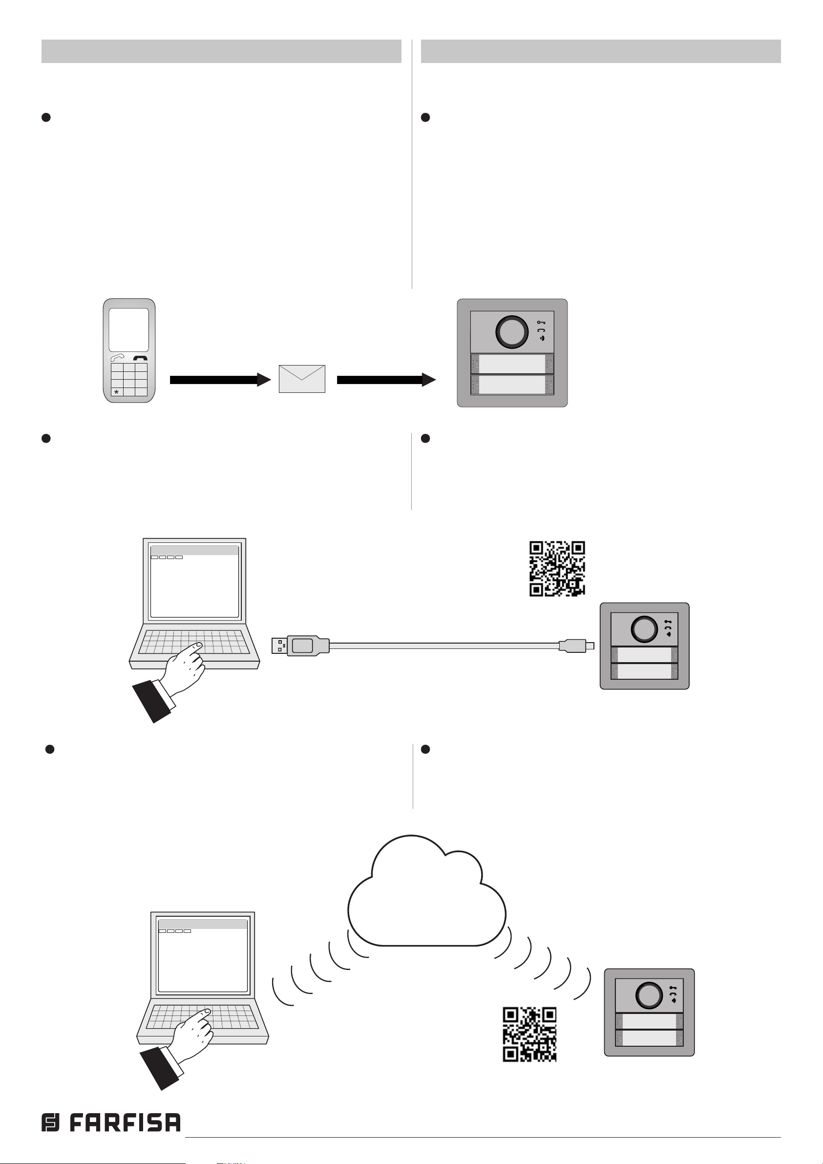
Il dispositivo AB3G supporta diversi tipi di programmazione:
Programmazione remota con messaggi SMS.
È possibile programmare il dispositivo AB3G a distanza con
l’invio di appositi messaggi SMS.
Il messaggio deve cominciare e terminare con il punto e virgola
seguito dal nome e dal valore del parametro da programma-
re. Se si devono programmare più parametri essi possono
essere inclusi nello stesso SMS come negli esempi seguenti:
esempio 1 ;BMOD=0;
esempio 2 ;BMOD=0;KPA4=040713470;KPT1=30
Il nome ed i valori che possono assumere i parametri del
modulo AB3G sono riportati nei successivi paragra.
AB3G device supports dierent types of programming:
Remote programming using SMS.
It is possible to program the AB3G module by sending to it
an SMS with the parameters to be programmed. SMS should
start and end with dot coma symbol followed by the name and
the value of the parameter to be programmed. Whethe more
parameters should be programmed theyn can be included in
the same SMS as reported in the following examples:
exampe 1 ;BMOD=0;
example 2 ;BMOD=0;KPA4=040713470;KPT1=30
For name and values of parameters please refer to the next
paragraphs.
Programmazione con Personal Computer.
È possibile programmare il dispositivo AB3G con un PC
collegato tramite porta USB ed usando il software "mycom
manager".Il programma può essere scaricato dal sito Farsa
al seguente link:
mycom manager
;KPA4=040713470;KPB4=3864336480;KPC4=34967564326;KPT1=30;
;TBE=1;TBZS=6;TBZE=15;
;CLPEN=1;CLPOU=2;CLPI=0;CLP1=040414414;CLP2=042340880;
http://farsa.com/qr/mycom-manager/
Programming with PC.
You can program AB3G module connecting it to a PC with
its USB port and running on a PC the software "mycom
manager". Program can be downloaded from the Farsa site
at the following link:
Programmazione tramite Cloud.
È possibile programmare il dispositivo accedendo all'apposita
sezione del Cloud Farsa. La guida per l'accesso al Cloud si
può scaricare dal sito Farsa al seguente link:
;KPA4=040713470;KPB4=3864336480;KPC4=34967564326;KPT1=30;
;TBE=1;TBZS=6;TBZE=15;
;CLPEN=1;CLPOU=2;CLPI=0;CLP1=040414414;CLP2=042340880;
Programming using Cloud support.
You can program AB3G module by connecting to the proper
section of the Farsa Cloud. Instructions on how to access Farsa
Cloud can be downloaded from Farsa site at the following link:
http://farsa.com/qr/ab3g/
Italiano English
- 13 -
Mi 2546
Page 14
6 PARAMETRI
PULSANTE SINGOLO - SINGLE BUTTON
PULSANTE DOPPIO - DOUBLE BUTTON
SMS
SMS
6 PARAMETERS
Per congurare le funzionalità del modulo AB3G devono essere
programmati alcuni parametri. I parametri sono suddivisi in
sezioni logiche e sono descritti nei capitoli seguenti.
Nota. Nel dispositivo AB3G possono essere memorizzati
anche numeri telefonici Internazionali preceduti dal simbolo
+ e dal codice della Nazione; es.: +39340..., +44122....
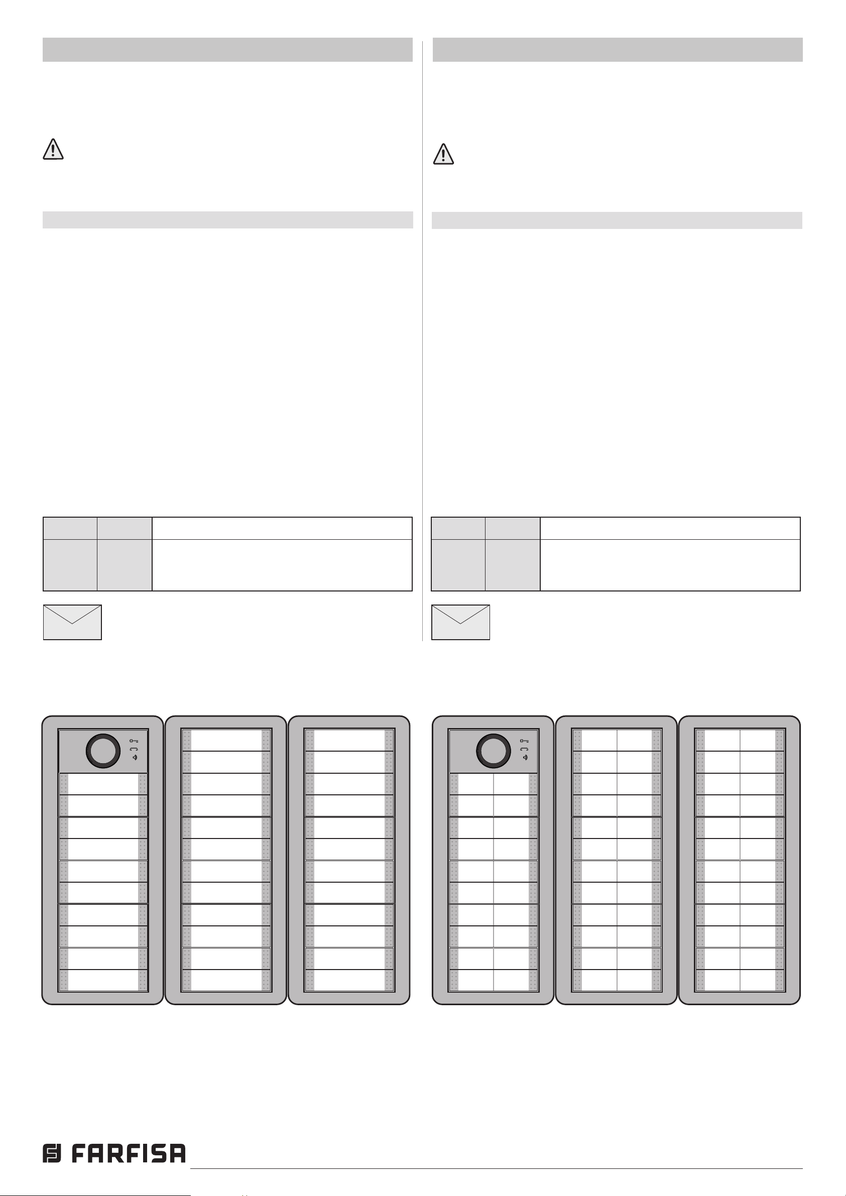
6.1 FUNZIONAMENTO A TASTO SINGOLO O DOPPIO
Il modulo AB3G ed i moduli tasti CT2138AB ad esso collegati
possono essere congurati sia come moduli con pulsanti
singoli che con pulsanti doppi.
6.1.1 Parametro BMOD=y
Il parametro BMOD seleziona la modalità di funzionamento dei
tasti di chiamata del modulo AB3G e di quelli degli eventuali
moduli tasti aggiuntivi CT2138 ad esso collegati.
To support versatile functionality of AB3G module dierent
parameters are used. The parameters are divided in logical
sections and are described in the following chapters.
Note. AB3G module can store also international phone
numbers by inserting + before the Country code;
i.e.:+39340….., +44122…..
6.1 SINGLE OR DOUBLE BUTTON OPERATING MODE
The AB3G module and the button modules CT2138 connected
to it can operate either as a single button or as a double buttons.
6.1.1 BMOD=y parameter
Parameter BMOD selects the operating mode of the calling
buttons of the AB3G module and of the additional button
modules CT2138 connected to it.
BMOD=0 funzionamento a tasto singolo, premendo sia il
tasto destro che quello sinistro si chiama lo stesso
utente.
BMOD=1 funzionamento a tasto doppio, premendo il tasto
destro o quello sinistro si chiamano utenti dierenti.
Esempio: Programmazione del parametro BMOD
Param. Valore Descrizione
BMOD 0 Il modulo AB3G ed i moduli tasti CT2138AB
ad esso collegati funzionano a tasto
singolo
Programmazione remota tramite SMS
;BMOS=0;
BMOD=0 Single button operating mode, by pressing either
the left or the right button system will call the same
user.
BMOD=1 Double button operating mode, by pressing the left
or right button system will call 2 dierent users.
Example: BMOD programming
Param. Value Description
BMOD 0 AB3G module and additional button
modules CT2138 connected to it operate
as a single button modules
Remote programming by SMS
;BMOD=0;
Parametro BMOD=0 - Parameter BMOD=0
11
12
1
2
3
4
5
6
7
8
9
10
13
14
15
16
17
18
19
20
21
22
23
24
25
26
27
28
29
30
31
32
33
34
Parametro BMOD=1 - Parameter BMOD=1
3
4
9
10
11
12
17
18
19
20
1
2
5
6
7
8
13
14
15
16
25
26
27
28
33
34
35
36
41
42
43
44
21
22
23
24
29
30
31
32
37
38
39
40
49
50
51
52
57
58
59
60
65
66
67
68
45
46
47
48
53
54
55
56
61
62
63
64
Italiano English
- 14 -
Mi 2546
Page 15
6.2 FUNZIONE ALLARME
IN1-IN2
GND
IN1-IN2
GND
IN1-IN2
GND
IN1-IN2
GND
6.2 ALARM SUPPORT
La funzione allarme è denita da alcuni parametri che sono
raggruppati in due sezioni: la prima contiene quelli utilizzati
per individuare le situazioni che generano una condizione
di allarme, la seconda quelli necessari a stabilire con quali
modalità l’allarme dovrà essere segnalato.
6.2.1 ATTIVAZIONE DEGLI ALLARMI
I parametri seguenti sono utilizzati per denire i criteri che,
se presenti ai terminali d’ingresso IN1 ed IN2, generano una
situazione di allarme.
6.2.1.1 Parametro INx=y
Una situazione di allarme può essere generata sia dall’ingresso
1 che dall’ingresso 2, per selezionare quale ingresso genera
la situazione di allarme è necessario attribuire al parametro
"x" il valore 1 o 2 (esempio IN1 o IN2).
Qualunque sia l’ingresso scelto, l’allarme può essere attivato sia
chiudendo l’ingresso prescelto verso massa (GND) sia aprendo
un circuito che normalmente chiude il morsetto d’ingresso
verso massa (interruzione “Loop” di corrente). Quando un
ingresso rivela una condizione di allarme invia un messaggio
SMS di notica ad un amministratore (vedi paragrafo 6.2.2.2
- parametri LN1 e LN2); è inoltre possibile inviare un SMS
anche quando l’ingresso che ha rilevato l’allarme ritorna nella
posizione normale. Le alternative descritte in precedenza si
programmano attribuendo al parametro "y" un valore da 0 a
6 secondo la tabella seguente.
Alarm function is supported by group of dierent parameters.
First section is used to dene the relations needed for alarm
to be trigged. The second section is used to report alarm.
6.2.1 ALARM TRIGGERING
Parameters are used to control (lter) the triggering of the
alarm inputs.
6.2.1.1 INx=y parameter
An alarm situation can be originated either by the input 1 or 2,
to select which input will generate the alarm it is necessary to
give to the "x" parameter the value 1 or 2 (example IN1 or IN2).
The alarm can be originated either by closing the selected input
to the ground (GND) or opening a circuit which normally closes
the selected input to the ground (opening a current loop). When
an input detects an alarm the devices automatically sends
an SMS message to a system administrator (see paragraph
6.2.2.2 – parameters LN1 and LN2); it is also possible to send
an SMS when the input, which has originated the alarm, is
restored to the normal status. All the alternatives described
above can be selected by giving at the "y" parameter a value
from 0 to 6 according to the next table.
Tabella 1. Parametri operativi per ingressi IN1 - IN2
y = Descrizione
0 Ingresso normalmente aperto; attivato con riferimento
di massa (GND)
1 Ingresso normalmente chiuso; attivato con interruzione
del “loop” di corrente (apertura ingressi)
2 Parametro non utilizzato
3 Parametro non utilizzato
4 Come parametro 0 con invio SMS anche al ritorno
nella posizione normale dell’ingresso INx
5 Come parametro 1 con invio SMS anche al ritorno
nella posizione normale dell’ingresso INx
6 Parametro non utilizzato
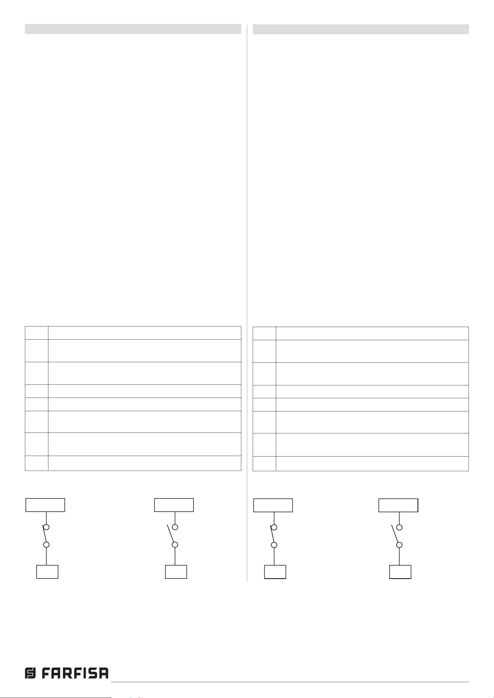
Schemi di collegamento dell’ingresso di allarme
Table 1. Operating parameters for inputs IN1 - IN2
y = Description
0 Normally open input; activated by shorting it to the
ground (GND)
1 Normally closed input; activated by opening the current
loop (opening the input)
2 Not used
3 Not used
4 As parameter 0 but the device will send an SMS also
when the INx input is restored
5 As parameter 1 but the device will send an SMS also
when the INx input is restored
6 Not used
Connection diagram for the alarm inputs
Contatto
normalmente chiuso
(loop di corrente)
Contatto
normalmente
aperto
Italiano English
- 15 -
Normally closed
contact
(current loop)
Normally open
contact
Mi 2546
Page 16
6.2.1.2 Parametro IDx=y
SMS
SMS
Il parametro IDx=y determina la durata in secondi dell’impulso
necessaria a far scattare il segnale di allarme all’ingresso 1 o
2 (x=1 o 2). La durata in secondi dell’impulso (y) può variare
da 0,5 secondi a 9999 secondi. L’impostazione predenita è
0,5 secondi con il valore del parametro "y" pari a 0.
6.2.1.2 IDx=y parameter
ID parameter determines the minimum length in seconds of
the pulse on input 1 or 2 (x=1 or 2) to trigger the alarm. The
pulse length (y) ranges from 0.5 to 9999 seconds.
The default time is 0.5 seconds when the parameters value
is 0.
6.2.1.3 Parametro DDx=y
Il parametro DDx=y è utilizzato per denire il ritardo in secondi
(y=0÷9999) tra il momento in cui la condizione di allarme si
verica all’ingresso 1 o 2 (x=1 o 2) e quando il dispositivo
acquisisce la segnalazione di allarme.
Tabella2.SignicatodeiparametriIN,IDeDD
Nome Descrizione
IN1 Modo di funzionamento dell’ingresso 1
IN2 Modo di funzionamento dell’ingresso 2
ID1 Durata dell’impulso dell’ingresso 1
ID2 Durata dell’impulso dell’ingresso 2
DD1 Ritardo acquisizione allarme ingresso 1
DD2 Ritardo acquisizione allarme ingresso 2
Esempio: Programmazione parametri IN, ID e DD
6.2.1.3 DDx=y parameter
The parameter DDx=y is used to dene the delay in seconds
(y=0÷9999) between the time the alarm input is triggered and
the time the alarm is acquired by the device.
Table 2. Meaning of the parameters IN, ID and DD
Name Description
IN1 Operating mode for input 1
IN2 Operating mode for input 2
ID1 Pulse length on input 1
ID2 Pulse length on input 2
DD1 Time delay for alarm acquisition on input 1
DD2 Time delay for alarm acquisition on input 2
Example: Programming of parameters IN, ID and DD
Param. Valore Descrizione
IN1 0 Allarme attivato mediante la connessione
a massa (GND) dell'ingresso 1
IN2 4 Allarme attivato mediante la connessione
a GND dell'ingresso 2 e SMS al ripristino
ID1 10 L'impulso all'ingresso 1 deve durare almeno
10 secondi per attivare l’allarme
ID2 0 L'impulso all'ingresso 1 deve durare almeno
0,5 secondi per attivare l’allarme
DD1 0 Segnalazione di allarme all’ingresso 1
acquisito dopo 0 secondi
DD2 15 Segnalazione di allarme all’ingresso 2
acquisito dopo 15 secondi
Programmazione remota tramite SMS
;IN1=0;IN2=4;ID1=10;ID2=0;DD1=0;DD2=15;
Param. Value Description
IN1 0 Alarm activated by connecting input 1 to
ground (GND)
IN2 4 Alarm activated by connecting input 2 to
GND and SMS on input restoring
ID1 10 Input 1 has to be valid for 10 second to
trigger the alarm
ID2 0 Input 2 has to be valid for 0,5 second to
trigger the alarm
DD1 0 Reporting of the alarm on input 1 is delayed
by 0 second
DD2 15 Reporting of the alarm on input 1 is delayed
by 15 seconds
Remote programming by SMS
;IN1=0;IN2=4;ID1=10;ID2=0;DD1=0;DD2=15;
Italiano English
- 16 -
Mi 2546
Page 17

6.2.2 SEGNALAZIONE REMOTA DI UN EVENTO DI
ALLARME
I parametri seguenti sono utilizzati per denire le modalità
con le quali il dispositivo AB3G segnala l’evento di allarme.
6.2.2 REMOTE REPORTING ALARM EVENTS
Parameters used to dene the way the AB3G module reports
the alarm event.
Nota. Il dispositivo AB3G invia messaggi SMS per la notica
di un evento di allarme.
6.2.2.1 Parametro TNx=y
Per la gestione del dispositivo devono essere individuati gli
amministratori del sistema, essi possono essere al massimo
5 e sono individuati dal parametro TNx (x=1÷5); nei parametri
TN1÷TN5 devono essere memorizzati i loro numeri di telefono
(y). I numeri degli amministratori (TN1÷TN5) sono utilizzati
anche per la segnalazione di un evento di allarme.
AB3G segnala l’allarme tramite l’invio di messaggi SMS.
6.2.2.2 Parametro LNx=y
Il parametro LNx=y ha molteplici signicati a seconda del valore
della variabile (x=1÷6) come riportato nella tabella seguente:
LN1 = y numeri di telefono a cui saranno inviati gli SMS per
un allarme generato dall’ingresso 1;
LN2 = y numeri di telefono a cui saranno inviati gli SMS per
un allarme generato dall’ingresso 2;
LN3 = y numeri di telefono a cui inviare un messaggio SMS
per la verica periodica del funzionamento del
dispositivo;
LN4 = y numeri di telefono a cui inviare un messaggio SMS
quando il credito è sotto la soglia (parametro LCV,
paragrafo 6.5.1.1) o la scheda SIM è vicino alla
scadenza (parametro SCV, parametro 6.5.1.1);
LN5 = y numeri di telefono a cui inviare SMS per ogni evento
NAC (vedi nota della tabella 3);
LN6 = y numeri di telefono a cui inviare i messaggi SMS di
avviso lista eventi piena.
Il parametro "y" assume un valore pari ai numeri delle memorie
(TN1÷TN5) dove sono memorizzati i numeri di telefono a cui
inviare i messaggi.
Esempi:
- se i messaggi devono essere inviati ai numeri TN1, TN3 e
TN4, il parametro "y" sarà pari a 134;
- se i messaggi devono essere inviati ai numeri TN1 e TN5
"y" sarà pari a 15.
Note. AB3G module send SMS messages for reporting alarm
events.
6.2.2.1 TNx=y parameter
For the management of the device 5 system administrators
(max) can be dened and they are identied by parameter
TNx (x=1÷5); in TN1÷TN5 parameters the phone numbers
(y) of the system administrators have to be stored.
The phone numbers of the administrators (TN1÷TN5) are also
used by AB3G module to send the alarm messages.
6.2.2.2 LNx=y parameter
Parameters LNx have several meanings according to the
value of "x" (x=1÷6) as reported in the following table:
LN1 = y telephone numbers to which SMS for alarm on input
1 will be sent;
LN2 = y telephone numbers to which SMS for alarm on input
2 will be sent;
LN3 = y telephone numbers to which SMS for periodic
checking of the system will be sent;
LN4 = y telephone numbers to which SMS for low credit
(parameter LCV paragraph 6.5.1.1) on prepaid SIM
card or SIM card near to expire (parameter SCV
paragraph 6.5.1.1) will be sent;
LN5 = y telephone numbers to which SMS with NAC events
(see note of table 3) will be sent;
LN6 = y telephone numbers to which send SMS with the
warning of log list full.
The “y” parameters is a value (1 to 5 digit) composed of the
numerical link to the memories (TN1÷TN5) where are stored
the phone numbers of the administrators to whom send SMS.
Example:
- if SMS should be sent to phone numbers TN1, TN3 and
TN4, the value of “y” is 134;
- if SMS should be sent to administrators TN1 and TN5, the
value of “y” is 15.
6.2.2.3 Parametro LOT=x
Il parametro LOT=x è utilizzato per denire la durata in secondi
delle chiamate vocali (x=1÷9999). L’inizio della connessione
avvia il timer LOT, se la connessione vocale è ancora attiva
quando scade il tempo di conversazione, il dispositivo
disconnette automaticamente la connessione.
6.2.2.3 LOT=x parameter
Parameter LOT=x is used to set the conversation time in
seconds for voice calls (x=1÷9999). As soon as a voice
conversation starts, timer LOT is set, if the conversation is still
active when the LOT timer expires, the device automatically
closes the conversation.
Italiano English
- 17 -
Mi 2546
Page 18
SMS
SMS
Tabella 3. Parametri di segnalazione per gli allarmi
Table 3. Remote alarm reporting parameters
Nome Descrizione
TN1 1° numero di telefono dell’amministratore
TN2 2° numero di telefono dell’amministratore
TN3 3° numero di telefono dell’amministratore
TN4 4° numero di telefono dell’amministratore
TN5 5° numero di telefono dell’amministratore
LN1 Numeri di telefono (TN1÷TN5) collegati al 1°
ingresso di allarme
LN2 Numeri di telefono (TN1÷TN5) collegati al 2°
ingresso di allarme
LN3 Numeri di telefono (TN1÷TN5) a cui inviare un
SMS per il test periodico del dispositivo
LN4 Numeri di telefono (TN1÷TN5) a cui inviare un
SMS per la notica del credito insuciente o della
scadenza della scheda SIM
Name Description
TN1 1st administrator telephone number
TN2 2nd administrator telephone number
TN3 3rd administrator telephone number
TN4 4th administrator telephone number
TN5 5th administrator telephone number
LN1 Link of telephone numbers (TN1÷TN5) for alarm
on input 1
LN2 Link of telephone numbers (TN1÷TN5) for alarm
on input 2
LN3 Link for telephone numbers (TN1÷TN5) to which
send periodic test SMS
LN4 Link for telephone numbers (TN1÷TN5) to which
send low credit or SIM card expiration SMS
LN5 Numeri di telefono (TN1÷TN5) a cui inviare
la lista dei NAC (vedi nota)
LN6 Numeri di telefono (TN1÷TN5) a cui inviare la lista
degli eventi memorizzati nel dispositivo
LOT Durata massima della conversazione telefonica
Nota. Quando un telefono chiama o spedisce messaggi
al dispositivo AB3G ed il suo numero non è nella lista CLIP
o nei parametri KPA, KPB e KPC, si attiva una procedura di
sicurezza (NAC) ed il numero di telefono che ha originato una
procedura NAC può essere inviato via SMS ad un amministratore
per la notica (parametro LN5).
Esempio: Segnalazioni remote degli allarmi
Param. Valore Descrizione
TN1 042376678 Numero di telefono del 1° amministratore
LN5 Link for telephone numbers (TN1÷TN5) to
which send NAC (see note)
LN6 Link for telephone numbers (TN1÷TN5) to which
send Log
LOT Maximum conversation time
Note. When telephone number (calling or messaging
with AB3G module) is not on the CLIP list or in KPA,
KPB or KPC parameters, Not ACknowledge security event
(NAC) occurs. Telephone number responsible for this event
could be sent via SMS to TN administrators for notication
(LN5 parameter).
Example: Remote alarm reporting
Param. Value Description
TN1 042376678 1st administrator telephone number
TN2 040713470 Numero di telefono del 2° amministratore
LN1 13 Segnalazione allarme rilevata da ingresso
1 inviata ai numeri TN1 e TN3
LN2 1234 Segnalazione allarme rilevata da ingresso
2 inviata ai numeri TN1, TN2, TN3 e TN4
LN5 1 Messaggio notica evento NAC inviato
a TN1
LOT 60 Tempo massimo di conversazione 60s,
dopo questo tempo la connessione
vocale è interrotta automaticamente
Programmazione remota tramite SMS
;TN1=042376678;TN1=040713470;LN1=13;
LN2=1234; LN5=1;LOT=60;
TN2 040713470 2nd administrator telephone number
LN1 13 Alarm on input 1 are reported to TN1 and
TN3
LN2 1234 Alarm on input 2 are reported to TN1,
TN2, TN3 and TN4
LN5 1 NAC event sent to TN1
LOT 60 Conversation time is 60 seconds
Remote programming by SMS
;TN1=042376678;TN1=040713470;LN1=13;
LN2=1234; LN5=1;LOT=60;
Italiano English
- 18 -
Mi 2546
Page 19
PA
Relè 1
Relay 1
Relè 2
Relay 2
NO2
C2
NC1
NO1
C1
12Vac
PA =
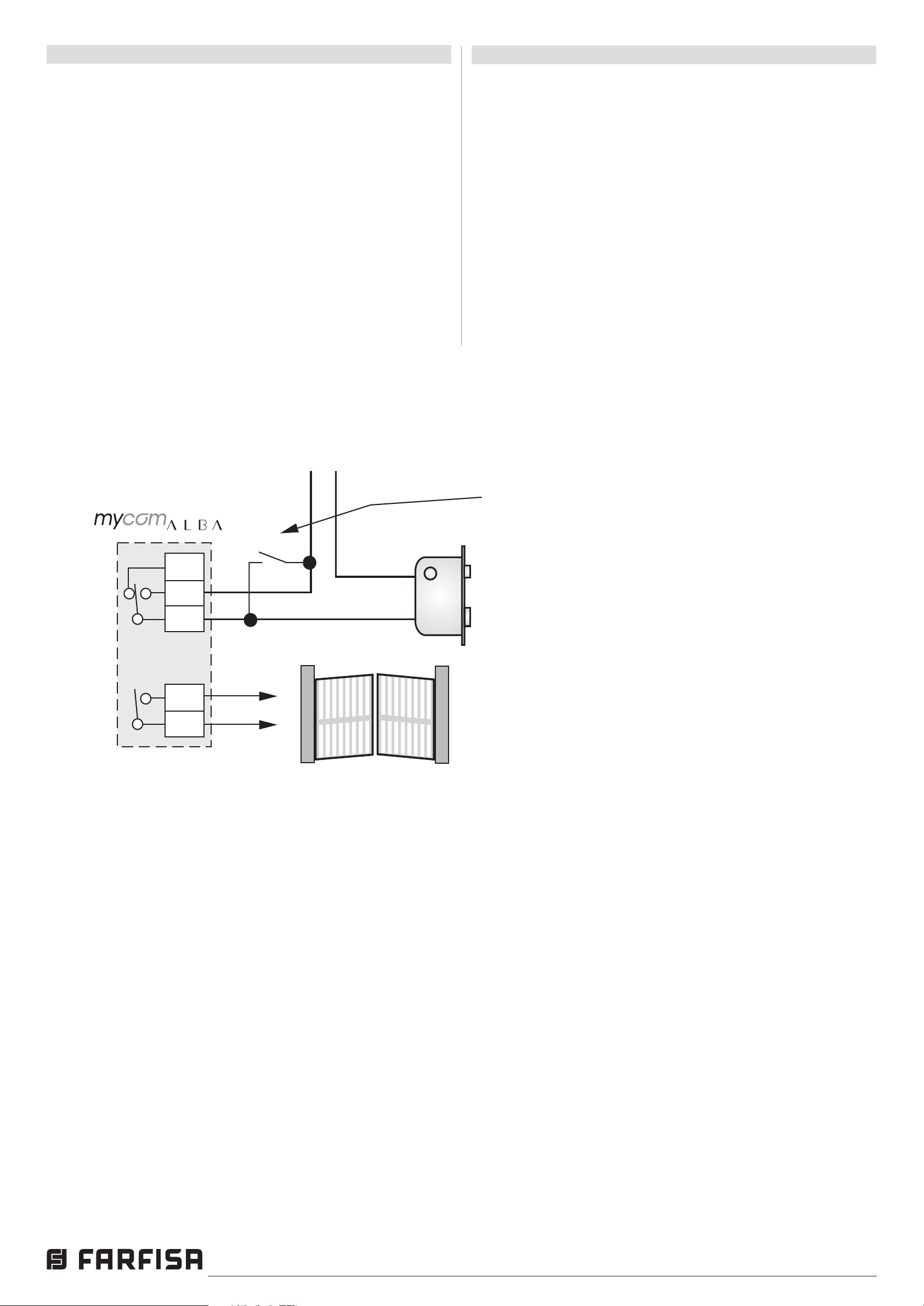
Pulsante apriporta (opzionale)
Door release push-button (optional)
Serratura elettrica (12Vca-1A max.)
Electric door lock (12VAC-1A max)
Cancello automatico
Automatic gate
Trasformatore Transformer
6.3 GESTIONE USCITE
6.3 OUTPUT MANAGEMENT
Il dispositivo AB3G ha 2 uscite che pilotano 2 relé; le uscite
possono supportare sia comandi specici , sia essere legate
al vericarsi di alcune condizioni di allarme ai morsetti di
ingresso. Il funzionamento delle uscite è denito dai prossimi
parametri.
6.3.1 Parametro OSx=y
Il dispositivo dispone di 2 uscite (x=1 o 2) realizzate con 2
relé. Le uscite possono essere congurate per funzionamenti
diversi come riportato nella tabella seguente:
OSx = 0 Uscita "x" disabilitata
OSx = 1 Funzionamento bistabile (modalità ON/OFF)
OSx = y Funzionamento monostabile (modalità ad impulso);
dove "y" è la durata dell’impulso in secondi (y=2÷9999)
Attenzione. Il parametro "y" deve essere maggiore di 1.
AB3G module supports 2 outputs which drive 2 relays; outputs
can support either specic commands or can be directly
activate by some alarm events. Their behaviour is dened
by the next parameters.
6.3.1 OSx=y parameter
AB3G module has 2 dedicated relay supported outputs.
Outputs can be congured to dierent behavior:
OSx = 0 Output "x" disabled
OSx = 1 Bi-stable toggle mode (ON-OFF mode)
OSx = y Mono-stable pulse mode; where "y" is the length in
seconds of pulse (y=2÷9999)
Attention. Parameter "y" must be greater than 1.
Esempio di collegamento delle uscite Example of connection for the outputs
Italiano English
- 19 -
Mi 2546
Page 20
6.3.2 Parametro ODx=y
SMS
SMS
Il parametro ODx=y è utilizzato per legare un evento di allarme
che si è vericato all’ingresso 1 o 2 (x=1 o 2) all’uscita 1 o 2
(y=1 o 2);
OD3=y è utilizzato per legare un evento NAC all’uscita 1 o
2 (y=1 o 2);
OD4=y abilita l'attivazione dei relé dell'uscita 1 o 2 (y=1 o
2) quando l'utente chiamato risponde;
ODx=0 signica che la funzione associata al parametro ODx
è disabilitata.
6.3.2 ODx=y parameter
Parameter ODx=y is used to link the alarm event on input 1
or 2 (x=1 or 2) directly to output 1 or 2 (y=1 or 2);
OD3=y links a NAC event to output 1 or 2 (y=1 or 2).
OD4=y enables the activation of relay of output 1 or 2 (y=1
or 2) when a user answers an incoming call;
ODx=0 means that the function related to ODx parameter
is disabled.
Tabella 4. Parametri di gestione delle uscite
Nome Descrizione
OS1 Modo di funzionamento dell’uscita 1
OS2 Modo di funzionamento dell’uscita 2
OD1=y Ingresso 1 collegato all’uscita y
OD2=y Ingresso 2 collegato all’uscita y
OD3=y Evento NAC collegato direttamente all’uscita y
OD4=y Uscita y attivata alla risposta
Esempio: Gestione delle uscite
Param. Valore Descrizione
OS1 1 Bistabile (modalità ON/OFF)
OS2 14 Monostabile (modalità ad impulso – durata
impulso 14 secondi)
Table 4. Output management parameters
Name Description
OS1 Output 1 mode of operation
OS2 Output 2 mode of operation
OD1=y Input 1 direct link to output y
OD2=y Input 2 direct link to output y
OD3=y NAC direct link to output y
OD4=y Output y is activated when a user answers a call
Example: output management
Param. Value Description
OS1 1 Bistable toggle mode
OS2 1 4 Monostable pulse mode (14 seconds pulse)
OD1 1 Ingresso 1 attiva l'uscita 1
OD2 2 Ingresso 2 attiva l’uscita 2
Programmazione remota tramite SMS
;OS1=1;OS2=14;OD1=1;OD2=2;
6.3.3 CONTROLLO DEI RELÉ CON TONI DTMF
Il dispositivo AB3G può controllare le due uscite a relé presenti
nel dispositivo utilizzando toni DTMF. Questa funzione è
molto utile nell’applicazione citofonica. Per controllare i relé,
durante la conversazione con il dispositivo AB3G, l’utente
deve comporre sul proprio telefono una combinazione di 2
cifre. La prima cifra identica il relé (1 o 2), la seconda cifra
indica se attivare (1) o disattivare (0) il relé. Nel caso in cui
l’utente desideri agire su entrambi i relé deve usare come
prima cifra lo 0. In questo caso i due relé sono controllati
contemporaneamente.
Nota. Per essere valida, la combinazione a 2 cifre
deve essere digitata entro 2 secondi e non deve
essere preceduta o seguita, per almeno 3 secondi,
da altri numeri. Importante: il dispositivo AB3G deve
essere in conversazione con l’utente per supportare la funzione
del controllo dei relé con i toni DTMF.
OD1 1 Input 1 activates output 1
OD2 2 Input 2 activates output 2
Remote programming by SMS
;OS1=1;OS2=14;OD1=1;OD2=2;
6.3.3 CONTROLLING OUTPUTS WITH DTMF
AB3G module can control the outputs with the use of DTMF.
This is very useful function in the intercom application. To
control the outputs the user must press, while in connection
with an AB3G module, the combination of 2 digits. First digit
is used to select the output (1 to 2), the second digit is used
to activate (1) or deactivate (0) the output. There is a special
case when the user can select as rst digit (output selection)
number 0, in this case all outputs are controlled at the same
time.
Note. Combination to be valid must be pressed in 2
seconds interval, and must be 3 seconds apart from
other entries. Important: AB3G module must be in
voice connection to support DTMF output control.
Tabella 5. Combinazione toni DTMF
Numero Descrizione
00 i 2 relé sono disattivati
01 i 2 relé sono attivati
10 relé 1 disattivato
11 relé 1 attivato
20 relé 2 disattivato
21 relé 2 attivato
Table 5. DTMF control
Number Description
00 Deactivate ALL outputs
01 Activate ALL outputs
10 Deactivate output 1
11 Activate output 1
20 Deactivate output 2
21 Activate output 2
Italiano English
- 20 -
Mi 2546
Page 21
6.4 LIVELLO DI SICUREZZA SL=x
SMS
SMS
6.4 SECURITY LEVEL SL=x
Il parametro SL=x, dove "x" può variare da 0 a 5, denisce
quanti e quali numeri di telefono degli amministratori,
memorizzati nella rubrica telefonica da TN1÷TN5, sono abilitati
a programmare e controllare da remoto il dispositivo AB3G;
per la programmazione fare riferimento alla tabella seguente:
Tabella 6. Parametro SL
x = Descrizione
0 Il dispositivo accetta tutte le chiamate e gli SMS.
1 Il dispositivo accetta chiamate o SMS soltanto dal
numero TN1.
2 Il dispositivo accetta chiamate o SMS soltanto dai
numeri TN1 e TN2.
3 Il dispositivo accetta chiamate o SMS soltanto dai
numeri TN1, TN2 e TN3.
4 Il dispositivo accetta chiamate o SMS soltanto dai
numeri TN1, TN2, TN3 e TN4.
SL=x parameter, where "x" ranges from 0 to 5, denes which
administrator telephone number stored in the contacts from
TN1÷TN5 can enter into programming and remote controlling
of the AB3G module; for programming refer to the following
table:
Table 6. SL parameter
x = Description
0 Device access all calls and SMS.
1 Only the number stored under parameter TN1 has
access to unit.
2 Numbers stored under parameters TN1 and TN2
have access to unit.
3 Numbers stored under parameters TN1, TN2 and
TN3 have access to unit.
4 Numbers stored under parameters TN1, TN2, TN3
and TN4 have access to unit.
5 Il dispositivo accetta chiamate o SMS da tutti i
numeri TN1, TN2, TN3, TN4 e TN5.
Nota. Se SL=0, l’accesso al dispositivo AB3G è
possibile da qualsiasi telefono. IMPORTANTE: se il
parametro SL non è programmato, il dispositivo accetta
TUTTE le chiamate. Da qualsiasi telefono è possibile, il controllo
remoto e la programmazione remota con SMS del dispositivo.
Esempio: Programmazione del parametro SL
Param. Valore Descrizione
SL 3 Solo i numeri salvati nelle memorie TN1,
TN2 e TN3 hanno accesso al dispositivo
Programmazione remota tramite SMS
;SL=3;
5 Numbers stored under parameters TN1, TN2, TN3,
TN4 and TN5 have access to unit.
Note. If SL is set to 0, the access to the AB3G device
is possible from any phone. IMPORTANT: if SL
parameter is not programmed the device can accept
ALL CALLS. Remote SMS programming and remote controlling
is possible from any phone.
Example: SL programming
Param. Value Description
SL 3 Only numbers stored under parameters
TN1, TN2 and TN3 have access to unit
Remote programming by SMS
;SL=3;
Italiano English
- 21 -
Mi 2546
Page 22
6.5 SCHEDA SIM PREPAGATA; INFORMAZIONI SUL
CREDITO E SULLA VALIDITÀ
6.5 PREPAID OR "PAY AS YOU GO" SIM CARD; CREDIT
AND EXPIRATION INFORMATION
Il dispositivo AB3G può essere utilizzato anche con le schede
SIM prepagate. Per gestire le peculiarità delle carte prepagate
il dispositivo è in grado di controllare automaticamente il
credito residuo e la scadenza della SIM.
Note.
- Il dispositivo AB3G invia automaticamente un SMS di avviso
quando il credito residuo è inferiore all’ammontare denito
dal parametro LCV (vedi paragrafo 6.5.1.1) o quando la
validità della scheda è vicina alla scadenza (vedi paragrafo
6.5.1.1 - parametro SCV).
- Per la gestione delle procedure dei diversi operatori telefonici
contattare i centri di assistenza tecnica FARFISA.
6.5.1 PROGRAMMAZIONE DEL CREDITO RESIDUO DELLA
SCHEDA PREPAGATA E VERIFICA DELLA VALIDITÀ
Per conoscere il credito residuo e controllare la validità della
scheda SIM sono utilizzati diversi parametri.
AB3G module can be used with prepaid and "pay as you go"
SIM cards and its limitations. To be able to overcome this
limitation of the prepaid SIM cards, AB3G module oers the
possibility of automatic checking mechanism for credit and
time expiration.
Notes.
- AB3G module automatically sends warning SMS when the
credit reaches the low level dened by LCV parameter (see
paragraph 6.5.1.1) or SIM card validity is near to expiration;
(see paragraph 6.5.1.1 - SCV parameter).
- To manage the procedures of dierent GSM providers
contact FARFISA technical support.
6.5.1 PROGRAMMING LOW CREDIT AND EXPIRATION
DATE FOR PREPAID OR "PAY AS YOU GO" SIM CARD
To be able to support credit and time validity of the SIM card
dierent parameters are used.
Nota: se almeno uno dei parametri CC1, CC2 e CC3
è programmato, il dispositivo chiede al gestore il
credito residuo ogni ora.
6.5.1.1 Parametri LCV=x e SCV=x
LCV=x è utilizzato per impostare il limite inferiore del credito
residuo (x=1÷9999). Se il credito residuo scende sotto al
limite x il dispositivo invia un messaggio SMS in accordo con
il parametro LN4 (paragrafo 6.2.2.2). Se LCV è programmato
a 0, non verrà inviato alcun avviso.
SCV=x è il periodo di validità operativa della scheda SIM varia
a secondo dei gestori. Il valore può essere programmato da
1 a 360 giorni (x=0÷360) e allo scadere il dispositivo invia
un messaggio SMS in accordo con il parametro LN4 (vedi
paragrafo 6.2.2.2). Se SCV non è programmato, ed è quindi
lasciato con l’impostazione di fabbrica o posto pari a 0, alla
scadenza non verrà inviato alcun tipo di avviso.
Per esempio in Italia SCV è pari a 360 giorni.
Note: if at least one of the parameters CC1, CC2
and CC3 is programmed, the device asks the provider
for credit every hour.
6.5.1.1 LCV and SCV parameter
LCV=x is used to set the limit for low credit event (x=1÷9999).
If the credit on prepaid or "pay as you go" SIM cards falls below
this limit SMS is sent in accordance with parameter LN4 (see
paragraph 6.2.2.2). If LCV is set to 0, no SMS will be sent.
SCV=x is the period of valid of SIM card which varies
among dierent GSM network providers. The value can be
programmed from 1 to 360 days (x=0÷360) and at the end of
programmed period the device will send an SMS according
to the parameter LN4 (see paragraph 6.2.2.2). The default
value (x=0) does not send any kind of expiry warning.
For example in Italy SCV is 360 days.
6.5.1.2 Numeri telefonici o stringhe CC1=x, CC2=y e CC3=z
I numeri o le stringhe (x, y e z) memorizzate in questi parametri
sono utilizzati per richiedere il valore del credito residuo al
gestore che ha emesso la scheda SIM prepagata.
CC1 - Questo parametro può essere programmato con la
stringa richiesta dai gestori che prevedano, per le
informazioni sul credito, l’invio di stringhe anziché la
chiamata ad un numero predenito.
CC2 - Questo parametro è programmato con il numero del
gestore Italiano di telefonia mobile TIM.
CC3 - Questo parametro è programmato con il numero del
gestore Italiano di telefonia mobile Vodafone.
6.5.1.2 CC1=x, CC2=y and CC3=z parameters
Number (x, y and z) used to check low credit value. They are
xed by each GSM providers.
CC1 - This parameter can be used by any 3G provider that
supports Unstructured Supplementary Service Data.
CC2 - This parameter is dedicated to Italian TIM mobile
provider.
CC3 - This parameter is dedicated to Italian Vodafone mobile
provider.
Italiano English
- 22 -
Mi 2546
Page 23
6.5.1.3 Parametri CREF, CTIM, CVODA
SMS
SMS
Questi parametri sono utilizzati per estrapolare il valore del
credito residuo dagli SMS di risposta dei diversi gestori. Per
la loro modica è necessario contattare il servizio clienti
FARFISA.
6.5.1.3 CREF, CTIM, CVODA parameters
Parameters are used to nd the credit value of the prepaid
SIM card. Strings under these parameters are used to parse
the replay message from the 3G provider. To modify these
parameters it is necessary to contact FARFISA technical
service.
CREF - Analizza la stringa per leggere il residuo credito
del gestore CC1.
CTIM - Analizza la stringa per leggere il residuo credito
del gestore CC2.
CVODA - Analizza la stringa per leggere il residuo credito
del gestore CC3.
Tabella 7. Parametri validità della scheda prepagata
Nome Descrizione
LCV valore del credito residuo sotto il quale viene
inviato un SMS di allerta.
SCV validità temporale della scheda SIM (in giorni)
prima di inviare un SMS di allerta
CC1 numero o stringa per la richiesta del credito residuo
(valido per tutti i gestori telefonici)
CC2 numero di telefono da comporre per la richiesta
del credito residuo all’operatore italiano TIM
CREF - Parsing string for the replay received from CC1
number.
CTIM - Parsing string for the SMS received from CC2
number.
CVODA - Parsing string for the SMS received from CC3
number.
Table 7. Prepaid or "pay as you go" card validity parameters
Name Description
LCV Low credit value, bottom limit for low credit event.
SCV Sim card validity time (in days)
CC1 Credit number for credit check universally used.
CC2 Credit number for credit check dedicated for Italian
TIM mobile provider.
CC3 numero di telefono da comporre per la richiesta
del credito residuo all’operatore italiano Vodafone
CREF Stringa di confronto per l’estrapolazione del credito
(*)
CTIM Stringa di confronto per l’estrapolazione del credito
(*)
CVODA Stringa di confronto per l’estrapolazione del credito
(*)
(*) Questi parametri sono programmati in fabbrica; per la loro
modica chiedere al servizio clienti FARFISA.
Esempio: Segnalazione credito residuo
Param. Valore Descrizione
residuo dal messaggio di risposta dell’operatore
chiamato con il numero CC1
residuo dal messaggio di risposta dell’operatore
chiamato con il numero CC2
residuo dal messaggio di risposta dell’operatore
chiamato con il numero CC3
CC3 Credit number for credit check dedicated for Italian
Vodafone mobile provider.
CREF String for parsing replay SMS message from CC1
(*)
CTIM String for parsing replay SMS message from CC2
(*)
CVODA String for parsing replay SMS message from CC3
(*)
(*) These parameters are factory stored; to modify them please
contact FARFISA technical service.
Example: Credit value
Param. Value Description
number.
number.
number.
CC1 *1345# Vodafone (UK)
CC2 4916 TIM Italia
CC3 404 Vodafone Italia
LCV 4 Il messaggio di credito residuo basso sarà
inviato se inferiore a 4 (€, £, $..)
Programmazione remota tramite SMS
;CC1=*1345#;CC2=4916;CC3=404;LCV=4;
CC1 *1345# Vodafone (UK)
CC2 4916 TIM Italy
CC3 404 Vodafone Italy
LCV 4 Low credit message will be send bellow 4
(€, £, $..)
Remote programming by SMS
;CC1=*1345#;CC2=4916;CC3=404;LCV=4;
Italiano English
- 23 -
Mi 2546
Page 24

6.6 PARAMETRI DI SISTEMA
6.6 SYSTEM PARAMETERS
I seguenti parametri sono utilizzati per configurare le
funzionalità del dispositivo AB3G.
6.6.1 Parametro HTN=x
HTN=x (x=0 o 1) è il parametro utilizzato per nascondere il
numero di telefono del dispositivo AB3G:
HTN = 0 il dispositivo non invia il proprio numero;
HTN = 1 il dispositivo invia il proprio numero.
Il valore di fabbrica è HTN=1
6.6.2 Parametro UDC=x
Il parametro è utilizzato per sincronizzare l’orologio del
dispositivo AB3G con l’orologio della rete 3G. L’utente deve
memorizzare in questo parametro il numero telefonico (x)
della scheda SIM del dispositivo AB3G.
6.6.3 Parametro RAN=x
Il parametro è utilizzato per la procedura di auto-risposta del
dispositivo AB3G. Il valore di "x" denisce il numero di squilli
(x=1÷20) dopo i quali il dispositivo AB3G risponde ad una
chiamata in arrivo. Anché il dispositivo risponda il numero
di telefono del chiamante deve essere compreso tra quelli
memorizzati nella lista TN1÷TN5 del dispositivo AB3G (vedi
paragrafo 6.2.2.1).
Dierent parameters are used to support versatile functionality
of AB3G module.
6.6.1 HTN=x parameter
HTN=x (x=0 or 1) is a parameter used in order to hide the
telephone number of the calling AB3G module.
HTN = 0 the device doesn't send its phone number;
HTN = 1 the device sends its phone number.
The default value is set to “1” which means that the number
of the calling device is sent.
6.6.2 UDC=x parameter
Parameter is used to synchronize the internal clock of AB3G
module to 3G network clock. User must enter here the phone
number (x) of the AB3G SIM card.
6.6.3 RAN=x parameter
Parameter is used to provide support for auto-answer options
for AB3G module. The value of "x" denes the numbers of rings
(x=1÷20) needed for AB3G module to answer the incoming
calls. The incoming number must be on the TN1÷TN5 list so
that AB3G module is answering (see paragraph 6.2.2.1).
6.6.4 Parametro TST=x
Il dispositivo AB3G può inviare periodicamente un SMS di
prova (vedi paragrafo 6.2.2.2, parametro LN3); il valore di "x"
denisce l’intervallo di tempo in ore (x=1÷240) con il quale
inviare i messaggi. Se si memorizza il valore 0, i messaggi
di test non sono inviati.
Esempio: attribuendo al parametro TST il valore 12, i numeri
associati al parametro “LN3” ricevono un messaggio di prova
ogni 12 ore.
6.6.5 Parametro MNF=x
Il parametro MNF=x denisce univocamente a quale gestore
di rete deve collegarsi il dispositivo AB3G, "x" è il codice MCC/
MNC del gestore che si desidera selezionare.
Il parametro MNF commuta il dispositivo dalla ricerca
automatica del gestore (x=0 o non programmato) a quella
manuale (x=codice MCC/MNC del gestore).
6.6.4 TST=x parameter
AB3G module can send periodically an SMS test message
(see paragraph 6.2.2.2, LN3 parameter); "x" value denes
the time interval in hours (x=1÷240) after which test SMS is
sent; if value 0 is stored SMS test messages are not sent.
Example: if TST value is programmed to 12, the numbers
linked to “LN3” receives a test message every 12 hours.
6.6.5 MNF=x parameter
Parameter MNF=x x the provider of GSM network to which
register AB3G module, "x" is the MCC/MNC code of the
chosen provider.
Parameter MNF switches the device from automatic searching
for the GSM provider (x=0) to a x GSM provider (x=MCC/
MNC provider code).
Esempio: i codici MCC/MNC per il gestore Vodafone (UK) è
23415, O2 (UK) è 23402, TIM (IT) è 22201 e Vodafone (IT)
è 22210.
Maggiori informazioni sui codici nazionali MCC/MNC sono
disponibili sul sito www.mcc-mnc.com.
6.6.6 Parametro MIC=x
Il parametro MIC=x (x=0 minimo ÷ 40 massimo) consente di
modicare il livello di sensibilità del microfono.
6.6.7 Parametro SPK=x
Il parametro SPK=x (x=0 minimo ÷ 20 massimo) consente di
modicare il livello di amplicazione dell’altoparlante.
6.6.8 Parametro ARST=x
Il parametro ARST=x (x=0÷9999) denisce il periodo di
tempo, in ore, dopo il quale eettuare il riavvio automatico
del dispositivo AB3G. Se si memorizza il valore 0 la funzione
è disabilitata.
Example: MCC/MNC codes for Vodafone (UK) is 23415, O2
(UK) is 23402, TIM (IT) is 22201 and Vodafone (IT) is 22210.
Other MCC/MNC codes can be found on www.mcc-mnc.com.
6.6.6 MIC=x parameter
MIC=x parameter (x=0 min ÷ 40 max) enables to change the
sensitivity level of microphone.
6.6.7 SPK=x parameter
SPK=x parameter (x=0 min ÷ 20 max) enables to change the
sound level of loudspeaker.
6.6.8 ARST=x parameter
ARST=x parameter (x=0÷9999) denes time interval, in hours,
for periodic auto-restart of AB3G module. If value 0 is stored
auto-restart is disabled.
Italiano English
- 24 -
Mi 2546
Page 25
6.6.9 Parametro MUT=x
SMS
SMS
Il parametro MUT=x (x=0 o 1) abilita o disabilita il tono durante
la chiamata ad un utente:
MUT = 0 il dispositivo emette il tono di chiamata;
MUT = 1 il dispositivo non emette il tono di chiamata.
6.6.9 MUT=x parameter
MUT=x parameter (x=0 or 1), enables or disables speaker
tone during the call:
MUT = 0 speaker tone is enabled
MUT = 1 speaker tone is disabled.
6.6.10 Parametro ADF=x
Il parametro ADF=x (x=1÷365) denisce il periodo di tempo
in giorni dopo il quale il dispositivo eettua una chiamata al
numero TN1 denito nel paragrafo 6.2.2.1. Questo servizio
è normalmente utilizzato per evitare che il gestore blocchi la
scheda SIM se per un certo numero di giorni non si eettuano
chiamate.
6.6.11 Parametro LNG
Il parametro LNG consente la selezione delle lingue:
0 - Inglese
1 - Italiano
2 - Sloveno
3 - Croato
4 - Olandese
5 - Francese
6 - Spagnolo
7 - Tedesco
6.6.10 ADF=x parameter
ADF=x parameter (x=1÷365) x the period in days after which
the device will call automatically the administrator TN1 dened
in paragraph 6.2.2.1. This feature is normally used to avoid
that the GSM provider will block the SIM card if no calls are
made within a certain number of days.
6.6.11 LNG parameter
LNG parameter switches between the preprogrammed
languages:
0 - English
1 - Italian
2 - Slovenian
3 - Croatian
4 - Dutch
5 - French
6 - Spanish
7 - German
6.6.12 parametro BUZ=x
Il parametro BUZ=x (x=0 o 1) è utilizzato per controllare il buzzer
del dispositivo AB3G. Il buzzer è utilizzato per segnalazioni
sonore durante il funzionamento del dispositivo.
BUZ = 0 signica buzzer OFF (disabilitato);
BUZ = 1 signica buzzer ON (abilitato).
Tabella 8. Parametri di sistema
Nome Descrizione
UDC Numero telefonico del dispositivo AB3G
RAN Numero di squilli per la risposta automatica
HTN Nasconde il numero di telefono
TST Intervallo per l’invio SMS di prova
MNF Selezione manuale/automatico del gestore telefonico
MIC Controllo della sensibilità del microfono
6.6.12 BUZ=x parameter
BUZ=x parameter (x=0 or 1) is used to control the buzzer
of AB3G module. Buzzer is used for signalling during the
operation of the device:
BUZ = 0 buzzer OFF (disabled);
BUZ = 1 buzzer ON (enabled).
Table 8. System parameters
Name Description
UDC Telephone number of AB3G module
RAN Number of ringing before the device answers a call
HTN Hidden device telephone number
TST Time interval for sending SMS test message
MNF Manual/auto selection 3G provider
MIC Microphone sensitivity control
SPK Controllo del volume dell’altoparlante
ARST Intervallo per il riavvio automatico del dispositivo
ADF Intervallo per chiamata automatica all'amministratore
(chiama TN1)
GNL Scelta della lingua
BUZ Controllo del buzzer
Esempio: parametri di sistema
Param. Valore Descrizione
HTN 0 Numero di telefono nascosto del dispositivo
MNF 22201 Impostazione manuale del gestore 3G (TIM)
LNG 1 Impostazione lingua italiana
MIC 2 Livello sensibilità del microfono
SPK 25 Livello di amplicazione dell’altoparlante
TST 24 SMS di controllo periodico inviato ogni 24 ore
SPK Loudspeaker volume control
ARST Time interval for auto-reset of AB3G module
ADF Time interval for auto dial to administrator
(Call TN1)
GNL Language selection
BUZ Buzzer control
Example: System parameters
Param. Value Description
HTN 0 Hidden telephone number of the AB3G module
MNF 23402 Manual selection of the 3G provider (O2)
LNG 0 English language
MIC 2 Microphone sensitivity
SPK 25 Loudspeaker sound level
TST 24 24 hours periodic SMS test
BUZ 0 Buzzer non attivo
Programmazione remota tramite SMS
;HTN=0;MFN=22201;LNG=1;MIC=2;SPK=25;
TST=24;BUZ=0;
BUZ 0 Mute buzzer
Remote programming by SMS
;HTN=0;MFN=23402;LNG=0;MIC=2;SPK=25;
TST=24;BUZ=0;
Italiano English
- 25 -
Mi 2546
Page 26
6.7 MESSAGGI SMS
#
#
#
0C 1ASA
R
O
M
A
1C 1UC INA
2G 1ARAGE
Nome Numero
Rubrica
testo
fisso
descrizione personalizzata
** vedi nota
#
#
#
0H 1OUSE
L
O
N
DON
1K 1ITCHEN
2G 1ARAGE
Name Number
Contacts
fixed
free description
** see note
SMS
SMS
6.7 SMS MESSAGES EDITOR
È possibile inviare un breve messaggio SMS ogni volta che
si verica un evento di allarme. Il messaggio predenito è in
inglese, ma è possibile cambiare la lingua con il parametro
LNG. Ogni messaggio è composto da 3 parti e l’utente può
scrivere la prima parte del messaggio (#0, dove in genere si
indica la localizzazione del dispositivo) e la seconda parte del
messaggio (#1, dove in genere si indica in quale ambiente è
avvenuto l’evento di allarme che fa riferimento all'ingresso 1 e
#2 per il riferimento dell'allarme dell'ingresso 2)*; il dispositivo
AB3G aggiunge automaticamente la terza parte che riporta la
descrizione dell’evento di allarme. La lingua della terza parte
può essere modicata con il parametro LNG.
I messaggi sono memorizzati nella rubrica telefonica della
scheda SIM sotto tre utenti diversi:
#0 luogo dov'è installato il dispositivo = 1 (**)
#1 luogo dov'è posizionato il sensore dell'ingresso 1 = 1 (**)
#2 luogo dov'è posizionato il sensore dell'ingresso 2 = 1 (**)
It is possible to send an SMS message any time an alarm
event occurs. Default message is in English, but language
can be changed by LNG parameter.
Each message is composed of 3 parts and the user can write
the rst (#0, where normally is reported the place where the
device is installed), and the second part (#1, where normally
is reported the localization of the sensor which is connected
to input 1 and #2 where normally is reported the localization
of the sensor which is connected to input 2)*; AB3G module
automatically adds the third part which reports the alarm
description, language of third part can be changed with LNG
parameter.
Messages are stored in the phone book of the SIM card under
three dierent users:
#0 place of installation of the device = 1 (**)
#1 localization of input 1 = 1 (**)
#2 localization of input 2 = 1 (**)
Esempio
Note.
(*) Il nome, incluso il testo sso, non deve essere più lungo di
16 caratteri, perché è memorizzato come nome utente nella
rubrica della scheda SIM; anche lo spazio è considerato
come un carattere (vedi esempio).
(**) Normalmente, anché gli utenti siano memorizzati in
rubrica, è necessario che abbiano anche un numero
telefonico, per cui è necessario associare a ciascun utente
un numero telefonico ttizio; per esempio 1.
Tabella 9. Parametri dei messaggi
Example
Notes.
(*) The name, including the xed text, must not exceed 16
characters because it is stored as contact name in the
contact list of SIM card; space is considered as character
(see example).
(**) Often to save a contact on the contact list it is
mandatory to save also its phone number, for this reason
it should be necessary to save together with the contact
name a dummy phone number, for example 1.
Table 9. Message parameters
Nome Descrizione
#0 Luogo dov'è installato il dispositivo; lo stesso per
tutti i messaggi di allarme
#1 Luogo dov'è posizionato il sensore che fa
riferimento all'ingresso 1
#2 Luogo dov'è posizionato il sensore che fa
riferimento all'ingresso 2
Esempio: Parametri dei messaggi
Param. Valore Descrizione
#0Casa 1 Denizione del luogo
#1Cucina 1 Ingresso allarme è dalla cucina
#2Garage 1 Ingresso allarme è dal garage
Programmazione remota tramite SMS
;#0Casa=1;#1Cucina=1;#2Garage=1;
Name Description
#0 Place where the device is installed, the same for
all alarm messages
#1 Place where sensor which refers to input 1 is
installed
#2 Place where sensor which refers to input 2 is
installed
Example: Message parameters
Param. Value Description
#0House 1 Location denition
#1Kitchen 1 Alarm input is from the kitchen
#2Garage 1 Alarm input is from the garage
Remote programming by SMS
;#0House=1;#1Kitchen=1;#2Garage=1;
Italiano English
- 26 -
Mi 2546
Page 27
6.8 CITOFONIA
SMS
SMS
6.8 INTERCOM
Per la funzionalità citofonica è necessario denire alcuni
parametri per congurare il sistema a seconda delle esigenze
dell’utente.
Il dispositivo AB3G supporta no a 200 tasti di chiamata
ciascuno con massimo 3 numeri telefonici.
6.8.1 Parametri KPAx, KPBx, KPCx
In questi parametri devono essere memorizzati i 3 numeri
telefonici da chiamare per l’applicazione citofonica che fanno
riferimento allo stesso tasto "x" (x=1÷200).
6.8.2 Parametro KPTx
Il parametro denisce il tempo massimo (in secondi) che
ha ciascun utente del gruppo per rispondere alla chiamata.
Il timer KPTx si attiva quando il telefono chiamato (KPAx)
inizia a squillare. Se il timer KPTx scade prima che avvenga
la connessione vocale 3G, il dispositivo AB3G chiama in
sequenza i numeri successivi (KPBx e KPCx).
Intercom functionality is supported by a set of parameters,
used to tweak the functionality to each user needs.
AB3G module supports up to 200 calling buttons each with
3 phone numbers maximum.
6.8.1 KPAx, KPBx, KPCx parameters
In these parameters should be stored the 3 phone numbers
which refer to the same “x” calling button x (x=1÷200).
6.8.2 KPTx parameter
This parameter sets the ringing time-out (in seconds) which
each group has to answer a call. Timer KPTx is set when
the rst called telephone (KPAx) starts to ring, if timer KPTx
expires before the rst user answers, automatically AB3G
module switches to call the second one (KPBx) of the same
calling group and then the third one (KPCx).
Tabella 10. Parametri Citofonia
Nome Descrizione
KPA1 Tasto di chiamata 1, 1° numero di telefono.
KPB1 Tasto di chiamata 1, 2° numero di telefono.
KPC1 Tasto di chiamata 1, 3° numero di telefono.
KPT1 Tasto di chiamata 1, tempo massimo di risposta
. .
. .
. .
KPA200 Tasto di chiamata 200, 1° numero di telefono.
KPB200 Tasto di chiamata 200, 2° numero di telefono.
KPC200 Tasto di chiamata 200, 3° numero di telefono.
KPT200 Tasto di chiamata 200, tempo massimo di risposta
Esempio: Parametri citofonici
Param. Valore Descrizione
KPA1 040713470 Tasto di chiamata 1, 1° numero di
telefono
Table 10. Intercom parameters
Name Description
KPA1 Calling button 1, 1st telephone number.
KPB1 Calling button 1, 2nd telephone number.
KPC1 Calling button 1, 3rd telephone number.
KPT1 Calling button 1, 1st ringing time-out.
. .
. .
. .
KPA200 Calling button 200, 1st telephone number.
KPB200 Calling button 200, 2nd telephone number.
KPC200 Calling button 200, 3rd telephone number.
KPT200 Calling button 200, 1st ringing time-out.
Example: Intercom parameters
Param. Value Description
KPA1 040713470 Calling button 1, 1st telephone
number.
KPB1 +3864336480 Tasto di chiamata 1, 2° numero di
telefono
KPC1 34967564326 Tasto di chiamata 1, 3° numero di
telefono
KPT1 30 Tasto di chiamata 1, tempo massimo
per la risposta (in secondi)
Programmazione remota tramite SMS
;KPA1=040713470;KPB1=3864336480;
KPC1=34967564326;KPT1=30;
KPB1 +3864336480 Calling button 1, 2nd telephone
number.
KPC1 34967564326 Calling button 1, 3rd telephone
number.
KPT1 30 Call group 1, ringing time-out (in
seconds).
Remote programming by SMS
;KPA1=040713470;KPB1=3864336480;KPC1=
34967564326;KPT1=30;
Italiano English
- 27 -
Mi 2546
Page 28
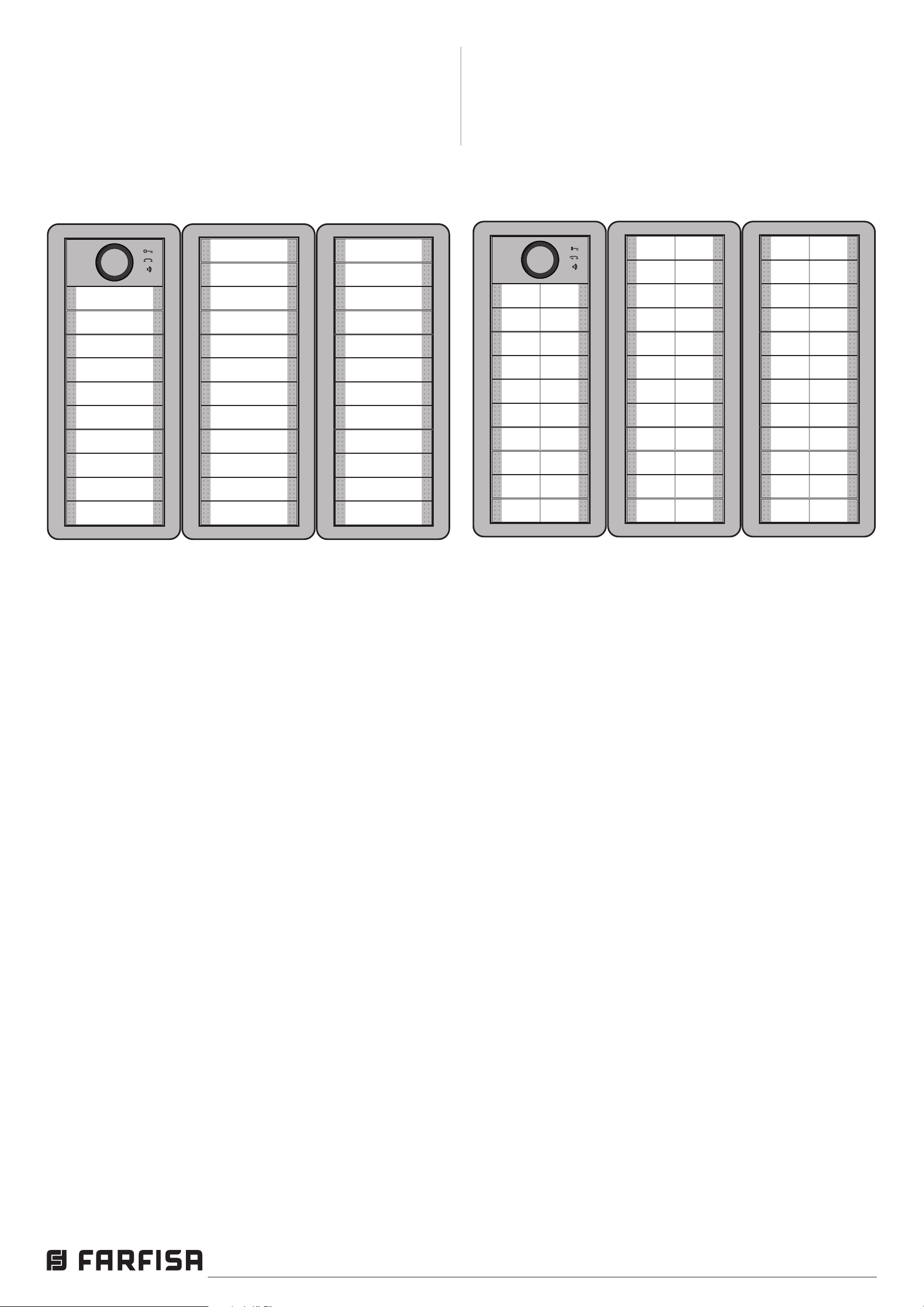
PARAMETRO BMOD=0 - PARAMETER BMOD=0
PARAMETRO BMOD=1 - PARAMETER BMOD=1
6.8.3 Corrispondenza tra pulsanti di chiamata e parametri
KPA, KPB e KPC
Nelle gure successive è indicata la corrispondenza tra pulsanti di chiamata e parametri KPA, KPB e KPC nel caso di
modalità di funzionamento a pulsante singolo (BMOD=0) o
doppio (BMOD=1)
6.8.2 Link between calling buttons and KPA, KPB and
KPC parameters
In the following gures are shown link between calling buttons and parameters KPA, KPB and KPC in case of single
(BMOD=0) or double (BMOD=1) buttons operating mode
PULSANTE SINGOLO - SINGLE BUTTON
KP
KP
KP
KP
KP
KP
KP
KP
KP
KP
KP
KP
ABC
ABC
ABC
ABC
ABC
ABC
ABC
ABC
ABC
ABC
ABC
ABC
KP
KP
KP
KP
KP
KP
KP
KP
KP
KP
ABC
ABC
ABC
ABC
ABC
ABC
ABC
ABC
ABC
ABC
1
2
3
4
5
6
7
8
9
10
KP
KP
KP
KP
KP
KP
KP
KP
KP
KP
KP
KP
ABC
ABC
ABC
ABC
ABC
ABC
ABC
ABC
ABC
ABC
ABC
ABC
11
12
13
14
15
16
17
18
19
20
21
22
23
24
25
26
27
28
29
30
31
32
33
34
PULSANTE DOPPIO - DOUBLE BUTTON
25
26
27
28
33
34
35
36
41
42
43
44
KP
KP
KP
KP
KP
KP
KP
KP
KP
KP
KP
KP
ABC
ABC
ABC
ABC
ABC
ABC
ABC
ABC
ABC
ABC
ABC
ABC
21
22
23
24
29
30
31
32
37
38
39
40
KP
KP
KP
KP
KP
KP
KP
KP
KP
KP
KP
KP
ABC
ABC
ABC
ABC
ABC
ABC
ABC
ABC
ABC
ABC
ABC
ABC
49
50
51
52
57
58
59
60
65
66
67
68
KP
KP
KP
KP
KP
KP
KP
KP
KP
KP
ABC
ABC
ABC
ABC
ABC
ABC
ABC
ABC
ABC
ABC
3
4
9
10
11
12
17
18
19
20
KP
KP
KP
KP
KP
KP
KP
KP
KP
KP
ABC
ABC
ABC
ABC
ABC
ABC
ABC
ABC
ABC
ABC
13
14
15
16
KP
ABC
KP
ABC
1
2
5
6
7
8
KP
KP
KP
KP
KP
KP
KP
KP
KP
KP
ABC
ABC
ABC
ABC
ABC
ABC
ABC
ABC
ABC
ABC
KP
KP
KP
KP
KP
KP
KP
KP
KP
KP
KP
KP
ABC
ABC
ABC
ABC
ABC
ABC
ABC
ABC
ABC
ABC
ABC
ABC
45
46
47
48
53
54
55
56
61
62
63
64
Italiano English
- 28 -
Mi 2546
Page 29
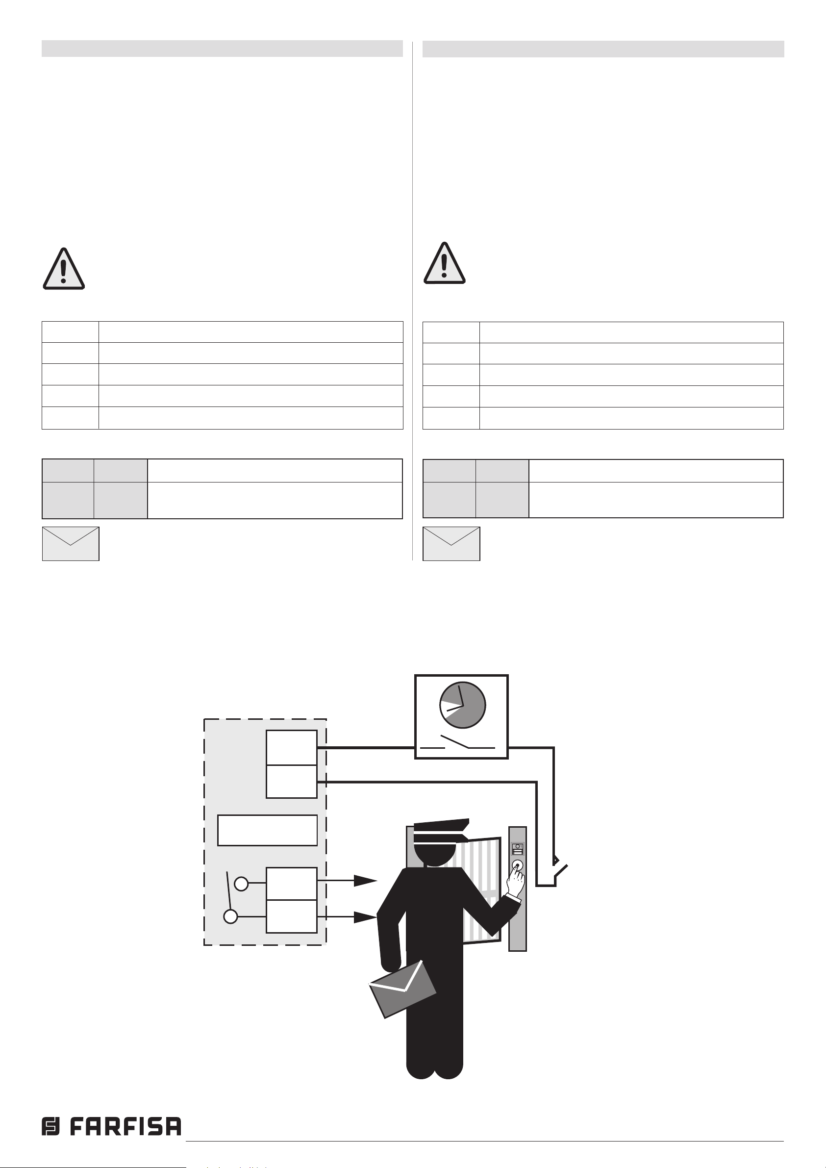
6.9 FUNZIONE "TRADE"
Relè 2
Relay 2
NO2
C2
IN1
GND
Timer
Trade button
AB3G
;OD1=2;
SMS
SMS
6.9 "TRADE" BUTTON
La funzione “Trade” permette, tramite un pulsante aggiuntivo
collegato ad uno degli ingressi, l'attivazione diretta del
relé dell’uscita selezionata (per esempio apertura cancello
pedonale).
6.9.1 Parametro OD1=y, OD2=y
I parametri OD1=y e OD2=y permettono di far corrispondere la
pressione di un pulsante, collegato rispettivamente all'ingresso
IN1 o IN2, all'attivazione diretta del relé di uscita 1 (y=1) o
uscita 2 (y=2) per azionare una serratura.
Nota. La funzione "Trade" può essere attivata anche
solo in determinati orari con l'aggiunta di un timer
esterno (non fornito dalla Farsa)
Tabella 11. Parametri del pulsante "Trade"
Nome Descrizione
OD1=1 Pulsante ingresso 1 attiva relé uscita 1
Trade button support is a user option to add an additional
button to provide direct (button pressed) activation of the
selected output (for example opening the pedestrian gate).
6.9.1 OD1=y, OD2=y parameters
Parameters OD1=y and OD2=y allow to link pressure of a
button, connected respectively to input 1 or 2, to the direct
activation of the relay of output 1 (y=1) or output 2 (y=2) for
door opening.
Note. "Trade" button can also be enabled at specific times using an external timer (not supplied by
Farsa).
Table 11. "Trade" button parameters
Name Description
OD1=1 Button input 1 activate relay output 1
OD1=2 Pulsante ingresso 1 attiva relé uscita 2
OD2=1 Pulsante ingresso 2 attiva relé uscita 1
OD1=2 Pulsante ingresso 2 attiva relé uscita 2
Esempio: Funzione "Trade"
Param. Valore Descrizione
OD1 2 Abilita il "pulsante Trade" collegato
all'ingresso 1 ad attivare l'uscita 2
Programmazione remota tramite SMS
;OD1=2;
Esempio funzione Trade con timer Example of the Trade function with a timer
OD1=2 Button input 1 activate relay output 2
OD2=1 Button input 2 activate relay output 1
OD1=2 Button input 2 activate relay output 2
Example: "Trade" function
Param. Value Description
OD1 2 Enable a Trade button connected to input
1 to activate output 2
Remote programming by SMS
;OD1=2;
Italiano English
- 29 -
Mi 2546
Page 30
6.10 FUNZIONE CLIP
6.10 CLIP FUNCTION
La funzione CLIP è utilizzata per attivare “senza costi
telefonici” i relé collegati alle uscite del dispositivo AB3G
utilizzando il proprio telefono. La funzione CLIP è disponibile
automaticamente per tutti gli utenti il cui numero di telefono è
memorizzato nei parametri KPA, KPB e KPC (600 utenti) ai
quali si possono aggiungere altri 200 utenti da memorizzare
nei parametri CLPx (CLP1÷CLP200). E' inoltre possibile
programmare il dispositivo in maniera tale che un qualsiasi
telefono che chiama il dispositivo AB3G abiliti la funzione
CLIP. I telefoni, i cui numeri sono abilitati alla funzione CLIP,
quando chiamano il dispositivo AB3G attivano il relé che è
stato specicato nel parametro CLPOU.
6.10.1 Parametro CLPEN
Parametro utilizzato per attivare la funzione CLIP; può
assumere il valore 0=funzione disabilitata, il valore 1= funzione
abilitata per gli utenti i cui numeri di telefono sono memorizzati
nel parametri KPA, KPB, KPC e nei parametri CLP1÷CLP200
oppure il valore 2=funzione abilitata per qualsiasi telefono
chiamante.
Attenzione: programmando il parametro CLPEN=2
qualsiasi telefono che chiami il numero telefonico del
modulo AB3G attiva i relè controllati dalla funzione
CLIP.
CLIP provides a “free of charge” option to control the 2 outputs
of AB3G module using a telephone.
CLIP function is automatically available for all the users whose
phone number is stored in KPA, KPB and KPC parameters
(600 users) to which other 200 users can be added by storing
their phone number in the CLP parametrs (CLP1÷CLP200). It
is also possible to program the device in such a way that any
phone calling the AB3G module operates the CLIP function.
Telephones, whose numbers are enabled for the CLIP function,
activate the output specied by parameter CLPOUT simply
calling AB3G module.
6.10.1 CLPEN parameter
This parameter enables the CLIP function; it can assume the
value 0=CLIP function disabled, the value 1=CLIP function
enabled for all the users whose phone number is stored in
the KPA, KPB, KPC and CLP1÷CLP200 parameters or the
value 2=CLIP function enabled for any calling phone.
Attention: programming parameters CLPEN=2 any
phone which makes a call to the AB3G module operates the relays controlled by the CLIP function.
6.10.2 Parametro CLPOU
Parametro utilizzato per scegliere quale relé di uscita sarà
controllato dalla funzione CLIP esso può assumere il valore
1 (funzione CLIP attiva il relé d'uscita 1) o 2 (funzione CLIP
attiva il relé d'uscita 2).
6.10.3 Parametro CLPI
Questo parametro, se impostato, permette di denire quale
condizione presente agli ingressi 1 o 2 è condizione necessaria
per il funzionamento della funzione CLIP. Esso può assumere
i valori 0, 1 e 2; il valore 0 signica che la funzione CLIP
è sempre attiva se il parametro CLPEN è stato impostato
ad 1; il valore 1 signica che la funzione CLIP è attiva se
contemporaneamente il parametro CLPEN è stato impostato
ad 1 ed all’ingresso 1 si vericano le condizioni ssate dal
parametro IN1 (vedi paragrafo 6.2.1.1); il valore 2 signica
che la funzione CLIP è attiva se contemporaneamente il
parametro CLPEN è stato impostato ad 1 ed all’ingresso
2 si vericano le condizioni ssate dal parametro IN2 (vedi
paragrafo 6.2.1.1).
6.10.2 CLPOU parameter
This parameters is used to select which output will be activated
by the CLIP function, it can assume the value 1 (CLIP function
will activate the relay connected to output 1) or the value 2
(CLIP function will activate the relay connected to output 2).
6.10.3 CLPI parameter
This parameter, if programmed, denes which condition at
input 1 or 2 must be present so that CLIP function will be
operative. CLPI parameter can assume values 0, 1 or 2;
value 0 means CLIP function is always operative if CLPEN
parameter has been set to 1; value 1 means CLIP function
is operative if CLPEN parameter has been set to 1 and at
the input 1 are present the conditions dened by parameter
IN1 (see paragraph 6.2.1.1); value 2 means CLIP function is
operative if CLPEN parameter has been set to 1 and at the
input 2 are present the conditions dened by parameter IN2
(see paragraph 6.2.1.1).
6.10.4 Parametri CLP1 ... CLP200
Numeri di telefono abilitati per la funzione CLIP in aggiunta
ai numeri memorizzati nei parametri KPA, KPB e KPC. I
numeri di telefono che non sono memorizzati nei parametri
CLP1÷CLP200 o nei parametri KPA, KPB e KPC non sono
in grado di operare sui relé di uscita utilizzando la funzionalità
CLIP; nel caso in cui i telefoni, i cui numeri non sono
memorizzati nei parametri CLIP1÷CLIP200 o nei parametri
KPA, KPB e KPC, chiamino il dispositivo AB3G, si attiverà
una procedura NAC (vedi nota della tabella 3 di pagina 18).
6.10.4 CLP1 … CLP100 parameters
Telephone numbers allowed to use the CLIP function in addition
to the numbers stored in the KPA, KPB and KPC parameters.
Telephone numbers not stored in the CLP1÷CLP200 or KPA,
KPB and KPC parameters can not use CLIP function. In the
case that a telephone, whose number is not stored in the
CLP1÷CLP200 or KPA, KPB and KPC parameters, will call
the AB3G module a NAC procedure starts (see note of table
3 on page 18).
Italiano English
- 30 -
Mi 2546
Page 31
Tabella 12. Parametri CLIP
SMS
SMS
Table 12. CLIP parameters
Nome Descrizione
CLPEN Abilitazione funzionalità CLIP
CLPOU Uscita attivata con la funzione CLIP
CLPI Ingresso condizione di attivazione
CLP1 1° numero CLIP
CLP2 2° numero CLIP
. .
. .
. .
CLP200 200° numero CLIP
Esempio: Parametri CLIP
Param. Valore Descrizione
CLPEN 1 Abilita la funzionalità CLIP
CLPOU 2 Uscita 2 attivata con la funzione CLIP
CLPI 0 Nessuna condizione d'ingresso per
l'attivazione
Name Description
CLPEN Enable CLIP functionality
CLPOU Output activated by CLIP function
CLPI CLIP input activation condition
CLP1 1st CLIP number
CLP2 2nd CLIP number
. .
. .
. .
CLP200 200th CLIP number
Example: CLIP parameters
Param. Value Description
CLPEN 1 Enable CLIP functionality
CLPOU 2 Output 2 activated by CLIP function
CLPI 0 No input condition to enable CLIP
function
CLP1 040414414 1° numero CLIP
CLP2 042340880 2° numero Clip
Programmazione remota tramite SMS
;CLPEN=1;CLPOU=2;CLPI=0;CLP1=040414414;
CLP2=042340880;
CLP1 040414414 1st CLIP number
CLP2 042340880 2nd CLIP number
Remote programming by SMS
;CLPEN=1;CLPOU=2;CLPI=0;CLP1=040414414;
CLP2=042340880;
Italiano English
- 31 -
Mi 2546
Page 32
6.11 LISTA EVENTI
SMS
SMS
Il dispositivo AB3G supporta la funzione “LOGGING” cioè la
memorizzazione della lista degli eventi che si sono vericati
e sono stati registrati dal dispositivo. AB3G registra gli eventi
CLIP, i comandi di apertura porta ricevuti dai morsetti d'ingresso
1 e 2 e gli eventi di allarme questi ultimi solo se il parametro
EVIN è stato programmato ad 1.
Il dispositivo registra il tipo di evento, l’ora ed il numero di
telefono o il numero dell’ingresso che ha originato l’evento.
6.11 EVENT LOGGING
AB3G module supports logging of specic events. AB3G
module logs CLIP, door opening commands received from
input 1 or 2 and alarm events, the latter ones only if parameter
EVIN has been programmed to 1.
Log event consists of event type, time and telephone number
or input number.
6.11.1 Parametro LOGN
Il parametro è utilizzato per denire il numero di eventi da
stampare a seguito di una richiesta PLOG; il parametro può
assumere valori tra 1 e 1000.
6.11.2 Parametro LOGI
Il parametro è utilizzato per denire dove memorizzare gli
eventi. L’utente può scegliere tra la memoria non volatile del
dispositivo AB3G (LOGI=0) o trasferire gli eventi ad un PC
collegato al dispositivo tramite la porta USB (LOGI=1).
6.11.3 Parametro ALC
Il parametro è utilizzato per denire il comportamento del
dispositivo AB3G quando la memoria del dispositivo, per la
funzione "LOGGING", è piena. L’utente può scegliere tra la
cancellazione automatica (ALC=1) o manuale (ALC=0) degli
eventi.
6.11.4 Parametro EVIN
Il parametro è utilizzato per abilitare la memorizzazione degli
allarmi che si presentano agli ingressi 1 o 2 nella lista eventi
(LOG).
EVIN = 0 gli allarmi non sono memorizzati nella lista eventi
EVIN = 1 gli allarmi sono memorizzati nella lista eventi
6.11.1 LOGN parameter
Parameter is used for dening the number of events printed
out on PLOG request. This parameters can assume values
from 1 to 1000.
6.11.2 LOGI parameter
Parameter is used to dene the memory used for logging of
events on AB3G module. User can select between non-volatile
memory on AB3G module (LOGI=0) or select to transfer
events directly via USB to PC (LOGI=1).
6.11.3 ALC parameter
Parameter is used to control behavior when log on AB3G
module is full. User can select between auto log clear (ALC=1)
or manual clear of log (ALC=0).
6.11.4 EVIN parameter
Parameter is used to enable storing of alarm events from
input 1 or 2 on the LOG list.
EVIN = 0 alarms are not stored in the event lists
EVIN = 1 alarms are stored in the event lists
Tabella 13. Parametri LOG
Nome Descrizione
LOGN Numero di eventi inviati alla stampa
LOGI Selezione del supporto per memorizzare gli eventi
ALC Modalità di cancellazione degli eventi
Esempio: Parametri LOG
Param. Valore Descrizione
LOGN 5 5 eventi verranno stampati a seguito di un
comando PLOG
LOGI 0 Memorizzazione sulla memoria non volatile
del dispositivo AB3G
ALC 1 Cancellazione automatica degli eventi
quando la memoria è piena
Programmazione remota tramite SMS
;LOGN=5;LOGI=0;ALC=1;
Table 13. LOG parameters
Name Description
LOGN Number of log events to be printed out
LOGI Selection of log memory
ALC Selection of memory clearing
Example: LOG parameters
Param. Value Description
LOGN 5 5 log events will be printed out on PLOG
command
LOGI 0 Log events stored on non-volatile memory
of AB3G module
ALC 1 Log is auto cleared when full
Remote programming by SMS
;LOGN=5;LOGI=0;ALC=1;
Italiano English
- 32 -
Mi 2546
Page 33
6.12 COMANDI SMS SPECIALI
SMS
SMS
6.12 SPECIAL SMS COMMANDS
Questi comandi possono essere inviati solo con un messaggio
SMS e sono utilizzati per controllare alcune funzioni speciali
del dispositivo AB3G.
6.12.1 Comandi ORC1, ORC2
I comandi sono utilizzati per controllare con un messaggio
SMS il relé dell’uscita 1 o 2; essi possono assumere il valore
1 (ORCx=1) per attivare direttamente l’uscita "x" o il valore 0
(ORCx=0) per disattivare l’uscita "x".
6.12.2 Comando SDCLR
Il comando SDCLR è usato per cancellare tutti i dati dalla
scheda SIM.
6.12.3 comando LCRL
Il comando cancella la lista degli eventi (funzione “LOGGING”)
dal dispositivo AB3G.
These commands can only be sent by SMS messages, and
are used to control some special functions of AB3G module.
6.12.1 ORC1, ORC2 commands
Command is used to control outputs 1 or 2 directly via SMS.
They can assume the value 1 (ORCx=1) to directly activate
output "x" or value 0 (ORCx=0) to deactivate output "x".
6.12.2 SDCLR command
SDCLR command is used to clear all data on SIM card.
6.12.3 LCRL command
Command clears log on AB3G module.
6.12.4 Comando CLPCLR
IL comando è utilizzato per cancellare tutti i numeri e le
impostazioni della funzione CLIP.
6.12.5 Comando MRES
Il comando è utilizzato per resettare manualmente il modulo
3G Cinterion presente nel dispositivo AB3G.
6.12.6 Comando SSRES
Il comando è utilizzato per resettare manualmente il dispositivo
AB3G.
6.12.7 Comando SPO
Il comando SPO è utilizzato per stabilire la posizione iniziale
dove memorizzare i dati nella scheda SIM.
SPO=x dove "x" è la prima cella di memoria utilizzata nella
SIM (normalmente x=1÷20).
6.12.4 CLPCLR command
Command is used to delete all CLIP numbers.
6.12.5 MRES command
Command is used to manually restart 3G Cinterion module
inside theAB3G module.
6.12.6 SSRES command
Command is used to manually restart AB3G module.
6.12.7 SPO Command
Command SPO is used to change the starting position where
data are stored in the SIM card memory.
SPO=x where "x" is the starting position used in the SIM
memory (usually x=1÷20).
Tabella 14. Parametri dei comandi speciali SMS
Nome Descrizione
ORC1 Controllo dell’uscita 1
ORC2 Controllo dell'uscita 2
SDCLR Cancella tutto il contenuto della SIM
LCRL Cancella la lista degli eventi del dispositivo AB3G
MRES Reset manuale del modulo 3G Cinterion
SSRES Reset manuale del dispositivo AB3G
Esempio: Comandi SMS speciali
Parametro Descrizione
;ORC1;=1 Attiva il relé dell’uscita 1
;ORC2;=0 Disattiva il relé dell’uscita 2
;SDCLR; Cancella tutti i dati della SIM
Table 14. Parameters of the special SMS commands
Name Description
ORC1 Direct control of output 1
ORC2 Direct control of output 2
SDCLR Delete all SIM content
LCRL Delete log on AB3G module
MRES Manual reset of 3G Cinterion module
SSRES Manual reset of AB3G module
Example: SMS commands
Command Description
;ORC1=1; Activate output 1
;ORC2=0; Deactivate output 2
;SDCLR; Clear all data on SIM
;LCRL; Cancella la lista eventi dal dispositivo AB3G
;CLPCRL; Cancella numeri ed impostazioni della funzione
CLIP
;MRES; Ripristino manuale del modulo 3G Cinterion
;SSRES; Ripristino manuale del dispositivo AB3G
;SPO=1; Dati memorizzati a partire dalla 1a cella
della memoria della scheda SIM
Italiano English
;LCRL; Delete log on AB3G module
;CLPCRL; Delete numbers and settings of the CLIP function
;MRES; Manual reset of 3G Cinterion module
;SSRES; Manual reset of AB3G module
;SPO=1; Data stored starting from thr 1st location of the
the SIM card memory
- 33 -
Mi 2546
Page 34
7 VERIFICA DEI PARAMETRI MEMORIZZATI
7 CHECKING STORED PARAMETERS
Con questa funzione l’utente può controllare le impostazioni
di tutti i parametri memorizzati nel dispositivo AB3G. Per
vericare il valore dei parametri memorizzati è necessario
inviare al dispositivo un SMS dal telefono di un amministratore
abilitato. L'SMS deve essere strutturato esclusivamente nel
modo seguente: ;nome parametro; (es. ;PLN;). E' possibile
vericare con un solo SMS più parametri scrivendo di seguito i
loro nomi separati dal ; (es: ;PLN;POD;PSL;). Di seguito sono
riportati i nomi dei parametri che possono essere vericati.
7.1 Tutti i parametri (PALL)
Inviando questo comando al dispositivo AB3G si ricevono alcuni
messaggi SMS con il valore di tutti i parametri programmati
nell’unità: ;PALL;
Attenzione: i messaggi SMS di risposta a questo
comando possono essere numerosi.
7.2 Vericadellaversionesoftware(PSW)
Inviando questo comando si riceve un messaggio SMS di risposta
con la versione del SW caricata nel dispositivo AB3G: ;PSW;
The user can check the settings of ALL parameters of the
AB3G module. To verify the values of stored parameters it
is necessary send a proper SMS from the telephone of an
authorized administrator. SMS must be strictly structured as
in the following: ;parameter name; (i.e.: ;PLN;). It would be
possible to verify several values of parameters, using a single
SMS, by writing the names of all the requested parameters
separated by ; (i.e.: ;PLN;POD;PSL;). In the next paragraphs
are reported the names of parameters which can be veried.
7.1 Receive all parameters (PALL)
By sending this command to AB3G module you receive SMS
messages with all parameters that are currently programmed
in the unit: ;PALL;
Attention: reply SMS can be many.
7.2 Check SW revision (PSW)
By sending this command to AB3G module you receive SMS
messages with current SW version of AB3G module: ;PSW;
7.3 Controllo dell’intensità del segnale GSM (PSQ)
Inviando questo comando si riceve un messaggio SMS di
risposta con l’intensità del segnale GSM: ;PSQ;
7.4 Numeri di telefono degli amministratori (PTN)
Inviando questo comando si riceve un messaggio SMS di
risposta con tutti i numeri telefonici programmati nelle memorie
TN1÷TN5: ;PTN;
7.5 Collegamenti LN1÷LN6 (PLN)
Inviando questo comando si riceve un messaggio SMS
di risposta con i collegamenti programmati nelle memorie
LN1÷LN6: ;PLN;
7.6 Parametri d'ingresso (PIN)
Inviando questo comando si riceve un messaggio SMS di
risposta con i valori dei parametri d’ingresso programmati
nelle memorie IN1÷IN2: ;PIN;
7.3 Check GSM signal level (PSQ)
By sending this command to AB3G module you receive SMS
messages with signal GSM level: ;PSQ;
7.4 Administrators telephone numbers (PTN)
By sending this command to AB3G module you receive SMS
message with all currently stored telephone numbers for
administrators (TN1÷TN5): ;PTN;
7.5 Links LN1÷LN6 (PLN)
By sending this command to AB3G module you receive SMS
message with all currently programmed links (LN1÷LN6):
;PLN;
7.6 Input parameters (PIN)
By sending this command to AB3G module you receive SMS
message with all currently programmed input parameters
(IN1÷IN2): ;PIN;
7.7 Congurazionid'ingresso(PID)
Inviando questo comando si riceve un messaggio SMS di
risposta con le congurazioni d’ingresso programmate nelle
memorie ID1÷ID2: ;PID;
7.8 Congurazionid'uscita(POD)
Inviando questo comando si riceve un messaggio SMS di
risposta con le congurazioni di uscita programmate nelle
memorie OD1÷OD3: ;POD;
7.9 Ritardoprimadell’acquisizionediunallarme(PDD)
Inviando questo comando si riceve un messaggio SMS di
risposta con il valore del tempo di ritardo prima dell’acquisizione
di un allarme programmato nelle memorie DD1÷DD2: ;PDD;
7.10 Livello di sicurezza per l’accesso al dispositivo (PSL)
Inviando questo comando si riceve un messaggio SMS di
risposta con il livello di sicurezza SL impostato: ;PSL;
7.7 Inputcongurations(PID)
By sending this command to AB3G module you receive SMS
message with all currently programmed input congurations
(ID1÷ID2): ;PID;
7.8 Outputcongurations(POD)
By sending this command to AB3G module you receive SMS
message with all currently programmed output congurations
(OD1÷OD3): ;POD;
7.9 Delay before dial value (PDD)
By sending this command to AB3G module you receive
SMS message with time delay before acquisition of an alarm
(DD1÷DD2): ;PDD;
7.10 Security level to access the device (PSL)
By sending this command to AB3G module you receive SMS
message with programmed SL security level: ;PSL;
Italiano English
- 34 -
Mi 2546
Page 35
7.11 Parametri d'uscita (POS)
Inviando questo comando si riceve un messaggio SMS di
risposta con i parametri di uscita programmati nelle memorie
OS1 e OS2: ;POS;
7.11 Output parameters (POS)
By sending this command to AB3G module you receive SMS
message with all currently programmed outputs parameters
(OS1 and OS2): ;POS;
7.12 Messaggi SMS di allarme (P#)
Inviando questo comando si riceve un messaggio SMS di
risposta con i messaggi SMS di allarme pre-programmati
(#0÷#2): ;P#;
7.13 Parametridicongurazione(PPA)
Inviando questo comando si riceve un messaggio SMS di
risposta con il valore dei parametri di congurazione (TST,
MNF ...): ;PPA;
7.14 Parametri richiesta del credito residuo (PCREF)
Inviando questo comando si riceve un messaggio SMS di
risposta con il valore dei parametri per la richiesta del credito
residuo (CREF, CVODA ...): ;PCREF;
7.15 Parametri CLIP (PCLP)
Inviando questo comando si ricevono alcuni messaggi SMS di
risposta con il valore dei parametri delle funzionalità correlate
alla funzione CLIP (CLPEN, CLPOU, CLPI, CLPx): ;PCPL;
7.12 Programmed SMS alarm messages (P#)
By sending this command to AB3G module you receive SMS
message with all currently programmed SMS alarm messages
(#0÷#2): ;P#;
7.13 Congurationparameters(PPA)
By sending this command to AB3G module you receive
SMS message with all currently programmed conguration
parameters (TST, MNF…): ;PPA;
7.14 Credit parameters (PCREF)
By sending this command to AB3G module you receive SMS
message with all currently programmed credit parameters
(CREF, CVODA…): ;PCREF;
7.15 CLIP parameters (PCLP)
By sending this command to AB3G module you receive SMS
message with all currently programmed CLIP functionality
related parameters (CLPEN, CLPOU, CLPI, CLPx): ;PCPL;
Attenzione: i messaggi SMS di risposta a questo
comando possono essere numerosi.
Nota
L’utente può utilizzare il comando ;PCLP= x, y, per limitare
la quantità di numeri CLIP da stampare.
x = numero iniziale
y = numero nale
Esempio
;PCLP=1,10; stampa i parametri dei primi 10 numeri della
funzione CLIP.
7.16 Parametri dei gruppi di chiamata citofonica (PKP)
Inviando questo comando si ricevono alcuni messaggi SMS
con tutti il valore dei parametri programmati per i gruppi utenti
citofonici (KPAx, KPBx, KPCx, KPNx, KP0x, KPTx): ;PKP;
Attenzione: i messaggi SMS di risposta a questo
comando possono essere numerosi.
Attention: Reply SMS can be many.
Note.
User can use ;PCPL=x,y; to limit the number of CLIP numbers
to be printed.
x = start number
y = end number
Example
;PCLP=1,10; prints rst 10 CLIP numbers.
7.16 Intercom call groups parameters (PKP)
By sending this command to AB3G module you receive
SMS message with all currently programmed intercom group
parameters (KPAx, KPBx, KPNx, KP0x, KPTx): ;PKP;
Attention: Reply SMS can be many.
Nota
L’utente può utilizzare il comando ;PKP=x, y; per limitare il
numero di gruppi di utenti citofonici da stampare.
x = gruppo iniziale
y = gruppo nale
Esempio
;PKP=1, 10; stampa i parametri dei primi 10 gruppi di utenti
7.17 Parametri speciali (PSPEC)
Inviando questo comando si riceve un messaggio SMS di
risposta con le impostazioni programmate nei parametri
speciali: ;PSPEC;
Note.
User can use ;PKP=x,y; to limit the number of call groups to
be printed.
x = start group
y = end group
Example
;PKP=1,10; prints rst 10 call groups settings.
7.17 Special parameters (PSPEC)
By sending this command to AB3G module you receive an SMS
message with all currently programmed special parameters
settings: ;PSPEC;
Italiano English
- 35 -
Mi 2546
Page 36
7.18 Credito residuo per schede SIM pre-pagate (PCCx)
Inviando questo comando si riceve un messaggio SMS di
risposta con il credito residuo presente sulla scheda SIM
prepagata; "x" può assumere il valore 1, 2 o 3 e denisce
rispettivamente quale stringa o numero chiamare tra quelli
memorizzati nelle memorie CC1, CC2 o CC3: ;PCC1; o
;PCC2; o ;PCC3; o ;PCN; (tutti i numeri).
7.18 Credit for prepaid or "pay as you go" SIM card (PCCx)
By sending this command to AB3G module you receive SMS
message with Credit amount on your prepaid or "pay as you
go" SIM card; "x" can assume the value 1, 2 or 3 and denes
which string or number to call among those respectively stored
in memories CC1, CC2 or CC3: ;PCC1; or ;PCC2; or ;PCC3;
or ;PCN; (all numbers).
7.19 Stato delle uscite (PORC)
Inviando questo comando si riceve un messaggio SMS di
risposta con lo stato delle uscite: ;PORC;
7.20 Stato degli ingressi (INS)
Inviando questo comando si riceve un messaggio SMS di
risposta con lo stato corrente degli ingressi: ;INS;
7.21 Lista degli eventi registrati dal dispositivo AB3G
(funzione “LOGGING”)
Inviando questo comando si ricevono alcuni messaggi SMS di
risposta con la lista degli eventi registrati dal dispositivo AB3G;
il numero di eventi registrati dipende dal valore impostato nel
parametro LOGN (vedi paragrafo 6.11.1): ;PLOG;
Attenzione: i messaggi SMS di risposta a questo
comando possono essere numerosi.
7.19 Status of the outputs (PORC)
By sending this command to AB3G module you receive SMS
message with current outputs state: ;PORC;
7.20 Status of inputs (INS)
By sending this command to AB3G module you receive SMS
message with current input state: ;INS;
7.21 AB3G module LOG
By sending this command to AB3G module you receive SMS
message with log on AB3G module; quantity of logs depends
on the value of LOGN parameter (see paragraph 6.11.1):
;PLOG;
Attention: Reply SMS can be many.
Italiano English
- 36 -
Mi 2546
Page 37

8 MODIFICA DEI PARAMETRI MEDIANTECOMANDI SMS
8 CHANGING PARAMETERS USING SMS COMMANDS
Come descritto nei capitoli 6 e 7, la programmazione e la
verica del valore dei parametri del dispositivo AB3G può
essere eettuata anche tramite messaggi SMS. Ogni comando
SMS deve iniziare e terminare con il punto e virgola. Se si
desidera ricevere, dal dispositivo AB3G, un messaggio SMS
di risposta a conferma dell’avvenuta programmazione, è
necessario mettere un “+” all’inizio del comando SMS.
Esempi:
- se si desidera controllare quali numeri di telefono sono
programmati nelle memorie T1÷T4 del dispositivo AB3G,
si deve utilizzare il seguente comando:
;PTN;
- se non ci sono numeri programmati il messaggio di risposta
sarà:
;TN1=0;TN2=0;TN3=0;TN4=0;
As described in paragraph 6 and 7, programming and
verication of parameters of AB3G module can also be done
by SMS messages. Each SMS command should start and
stop with a semicolon. If it is needed a conrmation reply from
AB3G module it is necessary to add “+” at the beginning of
SMS command.
Examples:
- if it is requested to verify which numbers are stored in
memories TN1÷TN4 of AB3G module, the following SMS
command should be sent to the device:
;PTN;
- if no numbers are stored under the memories T1÷T4 the
device will answer:
;TN1=0;TN2=0;TN3=0;TN4=0;
- se si desidera inserire i numeri di telefono TN1 e TN2 è
possibile utilizzare il seguente comando:
;TN1=040713470;TN2=+393406556749;
- se si desidera ricevere un messaggio SMS di conferma
scrivere “+” prima del comando:
;+TN1=040713470;TN2=+393406556749;
il messaggio SMS di ritorno sarà:
;TN1=040713470;TN2=+393406556749;
Nota. È possibile utilizzare la stessa procedura per tutti i
parametri di programmazione.
È possibile modicare più parametri con un solo messaggio
SMS scrivendo in sequenza i vari comandi separati dal punto
e virgola. Si consideri che il messaggio SMS non deve essere
più lungo di 160 caratteri (spazi inclusi).
Per esempio se si desidera modicare i seguenti parametri
TN3, IN1, IN2, OS1, OS2, ID1, LN1 e ricevere un messaggio
SMS di conferma, è necessario inviare al modulo AB3G il
seguente SMS:
;+TN3=+44123578;IN1=1;IN2=1;OS1=15;OS2=1;ID1=120;LN1=1;
- if it is required to store the telephone numbers of TN1 and
TN2, the following SMS command should be sent to the
device:
;TN1=040713470;TN2=+393406556749;
- if a conrmation SMS is required from the device write "+"
at the beginning of the command:
;+TN1=040713470;TN2=+393406556749;
- conrmation SMS will be:
;TN1=040713470;TN2=+393406556749;
Note. You can use the same programming procedure for all
parameters.
It is also possible to change dierent parameters with one
SMS. Consider that the SMS message should not be longer
than 160 characters (included space characters).
If it is necessary to change the following parameters TN3,
IN1, IN2, OS1, OS2; ID1, LN1 and a conrmation SMS is
also required, it is necessary to send to the AB3G module
the following SMS:
;+TN3=+44123578;IN1=1;IN2=1;OS1=15;OS2=1;ID1=120;LN1=1;
In pochi secondi si riceverà un messaggio SMS di risposta.
Se la procedura è stata eseguita correttamente, il messaggio
SMS di risposta conterrà esattamente gli stessi comandi inviati.
In a few seconds AB3G module will send back a replay SMS;
if the procedure was correct, reply SMS will contain exactly
the same parameters sent before.
Italiano English
- 37 -
Mi 2546
Page 38

9 PROGRAMMAZIONI DI FABBRICA
9 FACTORY SETTINGS
Nome Valore di Descrizione Pagina
fabbrica
#0 “Luogo” Testo principale SMS di allarme 26
#1 “Ingresso 1” Testo SMS allarme dell'ingresso 1 26
#2 “Ingresso 2” Testo SMS allarme dell'ingresso 2 26
ADF 0 Chiamata automatica a TN1 in giorni 25
ALC 1 Cancellazione automatica memoria (Log) 32
ARST 0 Periodo di tempo del riavvio automatico 24
BUZ 1 Controllo del buzzer 25
BMOD 1 Modalità tasto singolo o doppio 14
CC1 Vuoto Controllo credito residuo, operatore generico 22
CC2 Vuoto Controllo del credito residuo, TIM Italia 22
CC3 Vuoto Controllo del credito residuo, Vodafone Italia 22
CLP1 Vuoto 1° numero funzione CLIP 30
CLP100
Vuoto 100° numero funzione CLIP 30
Name Factory Description Page
settings
#0 “Location” SMS main head text 26
#1 “Input 1” SMS input 1 text 26
#2 “Input 2” SMS input 2 text 26
ADF 0 Auto dial functionality to TN1 25
ALC 1 Automatic log clear 32
ARST 0 Period of time for automatic reset 24
BUZ 1 Buzzer control 25
BMOD 1 Single or double buttons operation 14
CC1 Empty Check credit, universal provider 22
CC2 Empty Check credit, TIM Italy 22
CC3 Empty Check credit, Vodafone Italy 22
CLP1 Empty 1st CLIP number 30
CLP100
Empty 100th CLIP number 30
CLPCRL
CLPEN 1 Attivazione funzione CLIP 30
CLPI 0 Condizione di attivazione dell'evento CLIP 30
CLPOU 1 Controllo pin d'uscita con evento CLIP 30
CREF “EUR” Testo per estrarre il credito; operatore CC1 23
CTIM “EURO” Testo per estrarre il credito; operatore CC2 23
CVODA “E’.” Testo per estrarre il credito; operatore CC3 23
DD1 0 Ritardo segnalazione allarme ingresso 1 16
DD2 0 Ritardo segnalazione allarme ingresso 2 16
EVIN 0 Memorizzazione allarmi nella lista eventi 32
HTN 1 Nasconde il numero telefonico del dispositivo 24
ID1 0 Durata impulso per allarme ingresso 1 16
ID2 0 Durata impulso per allarme ingresso 2 16
IN1 0 Modalità di funzionamento ingresso 1 15
IN2 0 Modalità di funzionamento ingresso 2 15
Cancella tutti i numeri CLIP 33
CLPCRL
CLPEN 1 Enable CLIP functionality 30
CLPI 0 CLIP activation conditions 30
CLPOU 1 Output activated by CLIP function 30
CREF “EUR” Parse text (CC1 operator) 23
CTIM “EURO” Parse text (CC2 operator) 23
CVODA “E’.” Parse text (CC3 operator) 23
DD1 0 Input 1 delay before dialing 16
DD2 0 Input 2 delay before dialing 16
EVIN 0 Alarm storing on LOG list 32
HTN 1 Hidden telephone number of device 24
ID1 0 Input 1 length of pulse 16
ID2 0 Input 2 length of pulse 16
IN1 0 Operating mode input 1 15
IN2 0 Operating mode input 2 15
Delete all CLIP numbers 33
INS Stampa lo stato degli ingressi 36
KPAX Vuoto Pulsante di chiamata x, 1° numero telefonico 27
KPBX Vuoto Pulsante di chiamata x, 2° numero telefonico 27
KPCX Vuoto Pulsante di chiamata x, 3° numero telefonico 27
KPTX 25 Pulsante di chiamata x, tempo di risposta 27
LCLR Cancella la lista degli eventi 33
LCV 4 Limite credito residuo 22
LN1 Vuoto Ingresso 1 collegato ai numeri telefonici 17
LN2 Vuoto Ingresso 2 collegato ai numeri telefonici 17
LN3 Vuoto Numeri telefonici per invio SMS test periodici 17
LN4 Vuoto Numeri telefonici per invio SMS stato SIM 17
LN5 Vuoto Numeri telefonici per invio SMS eventi NAC 17
LN6 Vuoto Numeri tel. per invio SMS lista eventi piena 17
LNG 0 Selezione della lingua 25
LOGI 0 Supporto memorizzazione eventi 32
INS Prints status of the inputs 36
KPAx Empty Calling button x, 1st telephone number 27
KPBx Empty Calling button x, 2nd telephone number 27
KPCx Empty Calling button x, 3rd telephone number 27
KPTx 25 Calling button x, calling time 27
LCLR Clear the list of events 33
LCV 4 Low credit value 22
LN1 Empty Input 1, link to telephone numbers 17
LN2 Empty Input 2, link to telephone numbers 17
LN3 Empty Periodic SMS text, link to phone numbers 17
LN4 Empty SIM card rell, link to telephone numbers 17
LN5 Empty NAC, link to telephone numbers 17
LN6 Empty LOG full, link to telephone numbers 17
LNG 0 Language selection 25
LOGI 0 Log interface 32
LOGN 5 Numero di eventi inviati alla stampa 32
LOT 60 Durata massima della conversazione 17
MIC 22 Regolazione sensibilità microfono (0 ÷ 40) 24
MNF Vuoto Selezione manuale/autom. del gestore 3G 24
MRES Riavvio manuale del modulo 3G Cinterion 33
MUT 0 Abilita/disabilita il tono di chiamata 25
Italiano English
LOGN 5 Number of log events for printing out 32
LOT 60 Max conversation time 17
MIC 22 Microphone sensitivity setting (0 ÷ 40) 24
MNF Empty Manual/auto selection of 3G provider 24
MRES Manual restart 3G Cinterionmodule 33
MUT 0 Mute functionality 25
- 38 -
Mi 2546
Page 39

Nome Valore di Descrizione Pagina
fabbrica
Name Factory Description Page
settings
OD1 1 Ingresso 1 collegato all’uscita 1 o 2 29
OD2 2 Ingresso 2 collegato all’uscita 1 o 2 29
OD3 0 Evento NAC collegato all’uscita 1 o 2 16-29
OD4 0 Abilita l’uscita 1 o 2 alla risposta dell'utente 16-29
ORC1 Controllo del relé dell’uscita 1 33
ORC2 Controllo del relé dell’uscita 2 33
OS1 3 Modalità di funzionamento uscita 1 19
OS2 3 Modalità di funzionamento uscita 2 19
P# Stampa messaggi SMS #x 35
PALL Stampa di tutti i parametri 34
PCC1 Stampa numero richiesta credito (gest.gener.) 36
PCC2 Stampa numero richiesta credito (TIM Italia) 36
PCC3 Stampa numero richiesta credito (VOD. Italia) 36
PCLP Stampa parametri CLIP 35
PCN Stampa numeri credito CC1, CC2, CC3 36
OD1 1 Input 1 link to output 1 or 2 29
OD2 2 Input 2 link to output 1 or 2 29
OD3 0 NAC direct link to output 1 or 2 16-29
OD4 0 Enable output 1 or 2 when the user answers 16-29
ORC1 Control of output 1 33
ORC2 Control of output 2 33
OS1 3 Output 1 mode 19
OS2 3 Output 2 mode 19
P# Prints #x SMS messages 35
PALL Prints all parameters 34
PCC1 Prints number for credit (universal request) 36
PCC2 Prints number for credit (TIM Italy) 36
PCC3 Prints number for credit (VODAFONE Italy) 36
PCLP Prints CLIP parameters 35
PCN Prints number for credit CC1, CC2, CC3 36
PCREF Stampa stringhe confronto credito residuo 35
PDD Stampa parametri DDx 34
PID Stampa parametri IDx 34
PIN Stampa parametri INx 34
PKP Stampa numeri dei gruppi di chiamata 35
PLN Stampa collegamenti LNx 34
PLOG Stampa parametri lista eventi (log) 36
POD Stampa parametri ODx 34
PORC Stampa stato delle uscite 36
POS Stampa parametri OSx 35
PPA Stampa parametri di congurazione 35
PSL Stampa parametri SL 35
PSPEC Stampa parametri speciali 35
PSQ Stampa intensità segnale GSM 34
PSW Stampa versione software 34
PCREF Prints credit request parse parameters 35
PDD Prints DDx parameters 34
PID Prints IDx parameters 34
PIN Prints INx parameters 34
PKP Prints call groups parameters 35
PLN Prints LNx links 34
PLOG Prints log of AB3G module 36
POD Prints ODx parameters 34
PORC Prints the status of outputs 36
POS Prints OSx parameters 35
PPA Prints conguration parameters 35
PSL Prints SL parameter 35
PSPEC Prints special parameters 35
PSQ Prints GSM signal level 34
PSW Prints SW version 34
PTN Stampa numeri TNx 34
RAN 0 Numero di squilli per la risposta automatica 24
SCV 0 Tempo di validità della scheda SIM 22
SDCLR Cancellazione dati scheda SIM 12-33
SL 0 Livello di sicurezza 21
SPK 15 Regolazione volume dell'altoparlante (0 ÷ 20) 24
SPO 1 Posizione iniziale memoria scheda SIM 33
SSRES Riavvio manuale del dispositivo AB3G 33
TN1 Vuoto 1° numero di telefono amministratore 17
TN2 Vuoto 2° numero di telefono amministratore 17
TN3 Vuoto 3° numero di telefono amministratore 17
TN4 Vuoto 4° numero di telefono amministratore 17
TN5 Vuoto 5° numero di telefono amministratore 17
TST 24 intervallo di tempo per invio SMS di prova 24
UDC Vuoto Numero telefonico del dispositivo AB3G 24
PTN Prints TNx numbers 30
RAN 0 Number of rings for auto answer function 24
SCV 0 SIM card time validity 22
SDCLR Clear all data from SIM card 12-33
SL 0 Security level 21
SPK 15 Speaker volume level (0 ÷ 20) 24
SPO 1 Starting position of SIM card memory 33
SSRES Manual restart of AB3G module 33
TN1 Empty 1st administrator telephone number 17
TN2 Empty 2nd administrator telephone number 17
TN3 Empty 3rd administrator telephone number 17
TN4 Empty 4th administrator telephone number 17
TN5 Empty 5th administrator telephone number 17
TST 24 Time interval for test SMS 24
UDC Empty Telephone number of AB3G module 24
Italiano English
- 39 -
Mi 2546
Page 40
Cod. M527057400 Mi 2546
DATA DI ACQUISTO - DATE OF PURCHASE - DATE D’ACHAT - FECHA
DE COMPRA - DATA DE COMPRA - EINKAUFSDATUM
TIMBRO E FIRMA DEL RIVENDITORE
DEALER’S NAME AND ADDRESS
NOM ET ADRESSE DU REVENDEUR
NOMBRE Y DIRECCION DEL DISTRIBUIDOR
CARIMBO E ASSINATURA DO REVENDEDOR
STÄMPEL DES HÄNDLERS
ACIsrlFarsa
Via E. Vanoni, 3 • 60027 Osimo (AN) • Italy
La ACI Srl Farsa si riserva il diritto di modicare in qualsiasi momento i prodotti qui illustrati.
ACI Srl Farsa reserves the right to modify the products illustrated at any time.
La ACI Srl Farsa se réserve le droit de modier à tous moments les produits illustrés.
ACI Srl Farsa se reserva el derecho de modicar en cualquier momento los productos ilustrados aquí.
E’ reservada à ACI Srl Farsa o direito de modicar a qualquer momento os produtos aqui ilustrados.
Änderungen vorbehalten.
Tel: +39 071 7202038 • Fax: +39 071 7202037 • e-mail: info@farsa.com • www.farsa.com
CERTIFICATO DI GARANZIA
(condizioni valide solo per il Territorio Italiano)
La garanzia ha la durata di 24 mesi dalla data di acquisto, accertata o accertabile,
e viene esercitata dalla Ditta rivenditrice e, tramite questa, dai Centri Assistenza
Tecnica Autorizzati FARFISA.
La garanzia deve essere esercitata, pena la decadenza, entro otto giorni dalla sco-
perta del difetto.
LA GARANZIA NON E’ VALIDA SE NON DATATA E VIDIMATA CON TIMBRO E
FIRMA DEL RIVENDITORE ALL’ATTO DELL’ACQUISTO. CERTIFICATO UNICO
ED INSOSTITUIBILE.
Italiano English
- 40 -
AB3G
MATRICOLA - SET NUMBER - MATRICULE APPAREIL -
N° MATRICULA - N° DE MATRICULA - SERIENNUMMER
Directive2012/19/EU(WEEE-RAEE)
Smaltire il dispositivo secondo quanto prescritto dalle norme per la tutela
dell'ambiente.
Dispose of the device in accordance with environmental regulations.
Écouler le dispositif selon tout ce qu'a été prescrit par les règles pour la
tutelle du milieu.
Eliminar el aparato según cuánto prescrito por las normas por la tutela del
entorno.
Disponha do dispositivo conforme regulamentos ambientais.
Werden Sie das Gerät in Übereinstimmung mit Umweltregulierungen los.
Mi 2546
 Loading...