


Item #: 422474
Rev Date: 2015-05-13
Installation Manual
VHR150
Heat Recovery Ventilator
United States
10048 Industrial Blvd., Lenexa, KS, 66215
Tel.: 800.747.1762 • Fax: 800.487.9915
Canada
50 Kanalflakt Way, Bouctouche, NB, E4S 3M5
Tel.: 800.565.3548 • Fax: 877.747.8116
Fantech reserves the right to modify, at any time and without notice, any or all of its products’ features, designs, components and specifications to maintain their technological leadership position.
Please visit our website www.fantech.net for more detailed technical information.


 fantech

2
|
|
|
|
|
|
|
|
|
|
|
|
|
|
|
|
|
|
|
|
|
Note |
Warning/ |
Information |
Technical |
Practical tip |
||
|
|
|
Important |
|
information |
|
|
|
|
note |
|
|
|
PLEASE READ THIS MANUAL BEFORE INSTALLING UNIT
For residential use only |
|
Before installation careful consideration must be |
given to how this system will operate if connected to |
any other piece of mechanical equipment, i.e. a |
forced air furnace or air handler operating at a higher |
static pressure. After installation, the compatibility of the two pieces of equipment must be confirmed by measuring the airflow of the Heat Recovery Ventilator using the balancing procedure found in this manual. It is always important to assess how the operation of any HRV may interact with vented combustion equipment (i.e. Gas Furnaces, Oil Furnaces, Wood Stoves, etc.)
Products are designed and manufactured to provide reliable performance, but they are not guaranteed to be 100% free of defects. Even reliable products will experience occasional failures, and this possibility should be recognized by the user. If these products are used in a life support ventilation system where failure could result in loss or injury, the user should provide adequate back-up ventilation, supplementary natural ventilation or failure alarm system, or
acknowledge willingness to accept the risk of such loss or injury.
Your ventilation system should be installed in accordance with the local building code that is in effect, in absence of such requirements, it is recommenced to check with local authorities having jurisdiction in your area prior to installing this product.


 fantech

3
TABLE OF CONTENTS
DETERMINING YOUR AIRFLOW REQUIREMENT . . . . . . . . . . . . . . . . . . . . . . . . . . . 4
INSTALLATION EXAMPLES |
|
|
Fully dedicated system . . . . . . . . . . . . . . . . . . . . . . . . . . . . . . . . |
|
5 |
Partially dedicated system . . . . . . . . . . . . . . . . . . . . . . . . . . . . . . |
. |
6 |
Simplified Installation |
|
|
Option 1 . . . . . . . . . . . . . . . . . . . . . . . . . . . . . . . . . . |
. |
7 |
Option 2 . . . . . . . . . . . . . . . . . . . . . . . . . . . . . . . . . . . 8 |
||
EXTERIOR DUCTING INSTALLATION |
|
|
Weatherhood Location . . . . . . . . . . . . . . . . . . . . . . . . . . . . . . . . |
|
9 |
Installing the ducting to the weatherhood . . . . . . . . . . . . . . . . . . . . . . . . . |
. |
9 |
INTERIOR DUCTING INSTALLATION |
|
|
General Tips . . . . . . . . . . . . . . . . . . . . . . . . . . . . . . . . . . . . |
|
10 |
Installing duct to HRV . . . . . . . . . . . . . . . . . . . . . . . . . . . . . . . . |
|
10 |
Supply & Exhaust Air Grilles Location . . . . . . . . . . . . . . . . . . . . . . . . . . . |
|
10 |
DUCTING INSTALLATION EXAMPLES . . . . . . . . . . . . . . . . . . . . . . . . . . . . . . |
. 11 |
|
HRV INSTALLATION . . . . . . . . . . . . . . . . . . . . . . . . . . . . . . . . . . . . |
|
12 |
AIRFLOW ADJUSTMENT & BALANCING |
|
|
General preparation . . . . . . . . . . . . . . . . . . . . . . . . . . . . . . . . . |
|
13 |
Adjusting airflow using integrated balancing system . . . . . . . . . . . . . . . . . . . . . |
|
13 |
Balancing steps . . . . . . . . . . . . . . . . . . . . . . . . . . . . . . . . . . |
|
14 |
LOW VOLTAGE CONTROL SYSTEMS . . . . . . . . . . . . . . . . . . . . . . . . . . . . . . |
|
15 |
WIRING DIAGRAM . . . . . . . . . . . . . . . . . . . . . . . . . . . . . . . . . . . . . 16 |
||
TROUBLESHOOTING . . . . . . . . . . . . . . . . . . . . . . . . . . . . . . . . . . . . |
. 18 |
|
HRV MAINTENANCE CHART . . . . . . . . . . . . . . . . . . . . . . . . . . . . . . . . . |
. 19 |
|


 fantech

4
DETERMINING YOUR AIRFLOW REQUIREMENT
Room Count Method
|
|
Room classification |
Number of rooms |
CFM (L/s) |
CFM Required |
|
|
|
|
|
|
|
|
Master bedroom |
|
x 10 L/s (20 CFM) |
= |
|
|
Basement |
yes or no |
if yes add 10 L/s (20 CFM) |
= |
|
|
if no = 0 |
|||
|
|
Bedrooms |
|
x 5 L/s (10 CFM) |
= |
|
|
Living room |
|
x 5 L/s (10 CFM) |
= |
|
|
|
|
|
|
|
|
Others |
|
x 5 L/s (10 CFM) |
= |
|
|
|
|
|
|
|
|
Kitchen |
|
x 5 L/s (10 CFM) |
= |
|
|
|
|
|
|
|
|
Bathroom |
|
x 5 L/s (10 CFM) |
= |
|
|
Laundry room |
|
x 5 L/s (10 CFM) |
= |
1 CFM = 0.47 L/s |
|
|
|||
|
|
|
|
|
|
|
|
|
|
||
1 L/s = 2.13 CFM |
|
Utility room |
|
x 5 L/s (10 CFM) |
= |
|
|
|
|
|
|
|
|
|
Total Ventilation Requirements (add last column ) |
= |
|
|
|
|
|
|
|
ASHRAE method
Ventilation Air requirements
Floor area |
|
|
|
|
|
Bedrooms |
|
|
|
|
|
|
|
0-1 |
|
|
2-3 |
|
4-5 |
6-7 |
|
|
>7 |
Ft2 |
m2 |
CFM |
L/s |
CFM |
L/s |
CFM |
L/s |
CFM |
L/s |
CFM |
L/s |
|
|
|
|
|
|
|
|
|
|
|
|
< 1500 |
<139 |
30 |
14 |
45 |
21 |
60 |
28 |
75 |
35 |
90 |
42 |
1501-3000 |
139.1-279 |
45 |
21 |
60 |
28 |
75 |
35 |
90 |
42 |
105 |
50 |
3001-4500 |
279.1-418 |
60 |
28 |
75 |
35 |
90 |
45 |
105 |
50 |
120 |
57 |
4501-6000 |
418.1-557 |
75 |
35 |
90 |
42 |
105 |
50 |
120 |
57 |
135 |
64 |
6001-7500 |
557.1-697 |
90 |
42 |
105 |
50 |
120 |
57 |
135 |
64 |
150 |
71 |
>7500 |
>697 |
105 |
50 |
120 |
57 |
135 |
64 |
150 |
71 |
165 |
78 |
|
|
|
|
|
|
|
|
|
|
|
|
* ASHRAE 62.2-2010 Table 4.1, Ventilation and Acceptable Indoor Air Quality in Low-Rise Residential Buildings.
Bathroom: If the HRV is going to provide the required local exhaust ventilation for each bathroom with each a continuous 20 CFM (10 L/s), this ventilation rate can be considered as part of the whole-building ventilation rate.


 fantech
INSTALLATION EXAMPLES
Example only – duct configuration may differ depending on the model.
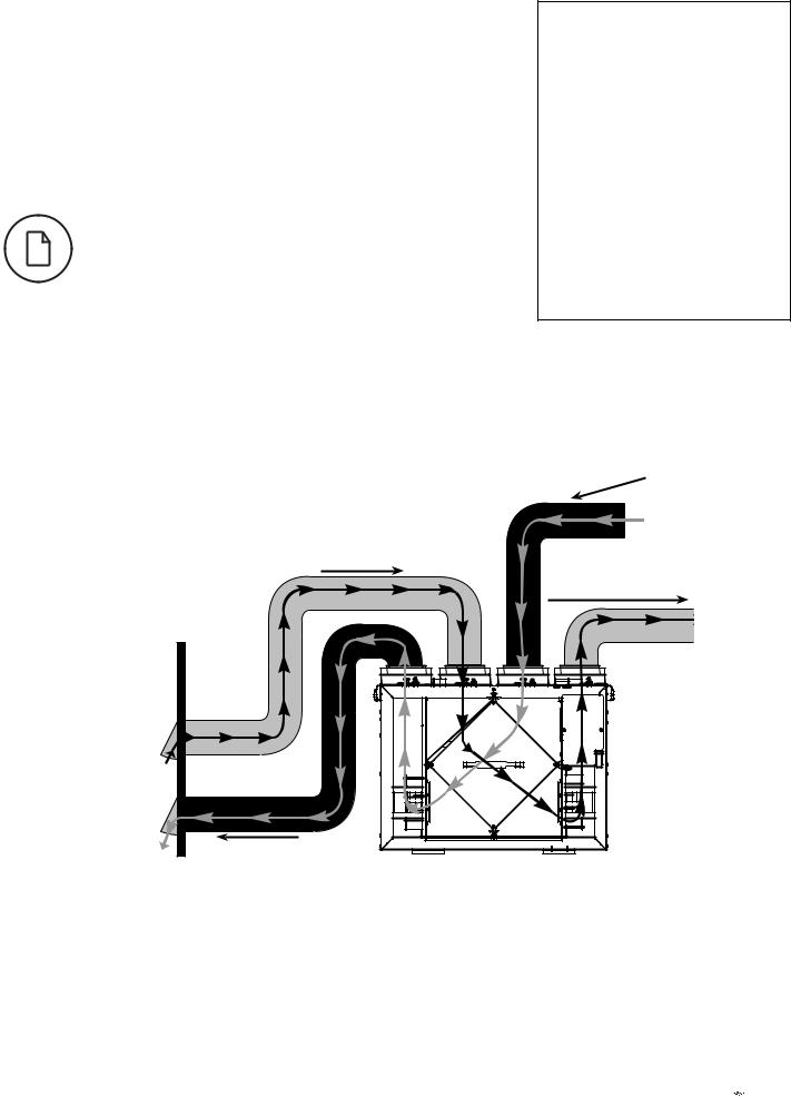
FULLY DEDICATED SYSTEM
BEST FOR NEW CONSTRUCTION
1.Stale air is drawn from key areas of the home requiring local exhaust (bathroom, kitchen, laundry room).
2.Fresh air is distributed directly to habitable rooms in the house (bedrooms, living room)
3.The HRV’s airflow must be balanced after installation using the procedure found in the section “AIRFLOW BALANCING”
5
Suggested installation for:
•Hydronic baseboard
•Infloor heating
•Electric baseboard
•Mini split heat pump
Benefits: Provides the best fresh air distribution in the house; lowest operation cost since the furnace/air handler unit is not needed.
HRV ducting for fully Dedicated System
Stale air from inside
Fresh air from outside
Fresh air to living areas
Outside
Stale air to outside


 fantech
6
INSTALLATION EXAMPLES (CONT'D)
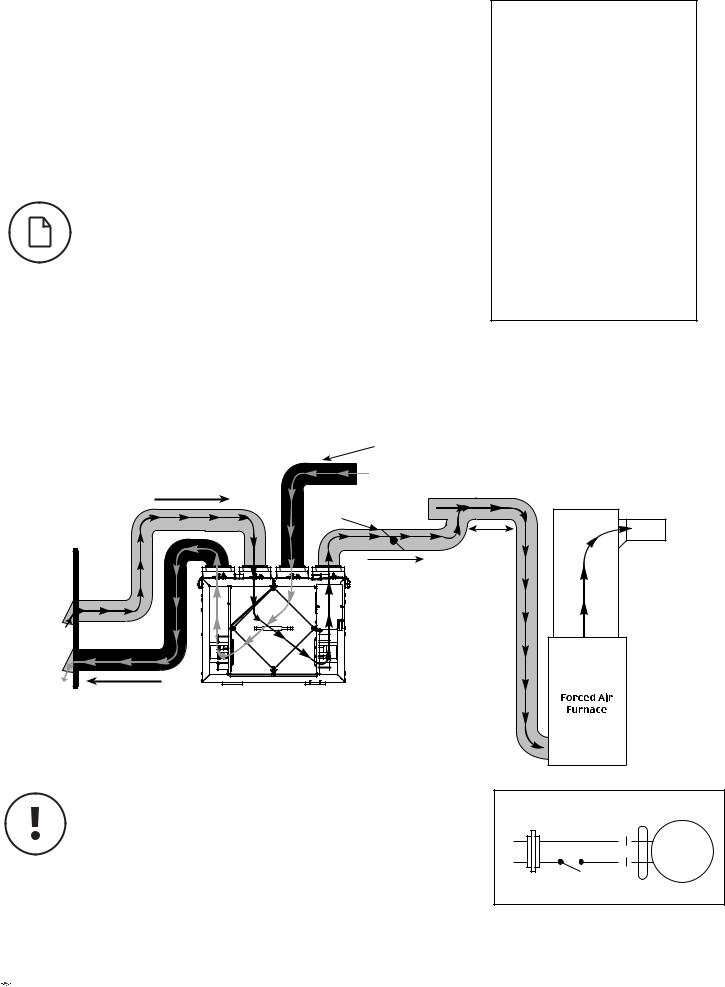
DIRECT CONNECTION of the FRESH air to living area to the RETURN PLENUM of the AIR HANDLER (Stale air drawn from key areas of home)
PARTIALLY DEDICATED SYSTEM (BETTER)
1.Furnace blower must operate when ventilation from HRV is required. The
furnace should be set to run continuously or interlocked with HRV
2.Stale air is drawn from key areas of the home (bathroom, kitchen, laundry room).
3.Fresh air is supplied to the return air plenum of the furnace.
4.Due to the difference in pressure between the HRV and the equipment it is being connected to the HRV’s airflow must be balanced on site, using the procedure found in the section “AIRFLOW BALANCING”
Suggested installation for:
•Central furnace (air handling unit or central air conditioners)
•When ducting fresh air to living area is not possible or practical, i.e. expensive or when the central AHU will operate year-round.
Benefits: Conditions the fresh air prior to distributing it throughout the house
HRV/ Furnace ducting for Partially Dedicated System
Stale air from inside
Fresh air from outside
Motorized Damper
Outside
Stale air to outside
1 m (3' 3")
min. Fresh air recommended
to living
areas
Cold air return
* Unit airflow should be balanced while HRV is on “Normal” speed and furnace blower is running.
Fantech heat recovery ventilators (HRV) that use a supply fan shutdown for frost prevention do not include an outdoor air motorized damper. If you are using a simplified installation, i.e. connecting the HRV supply air duct to a furnace's return air duct, the HRV must operate continuously. When the HRV is turned off, no warm exhaust air will flow through the HRV but the furnace's fan will continue to draw in outdoor air directly into the furnace. If it's cold outside, cold air will be introduced, without re-heating, directly into the furnace.
If the HRV is installed such that the homeowner may turn off the HRV during the winter, we recommend installing a motorized damper between the HRV's supply air and the furnace's return air duct that closes when the HRV is not operating. See wiring diagram (figure 1). You may also choose to use a Fantech HRV that uses a recirculation defrost that incorporates an outdoor air damper.


 fantech
24 VAC Transformer
24V |
|
|
120V |
Damper |
|
Motor |
||
|
||
COM |
NO |
HRV Furnace interlock
See page 16.
Figure 1
*Transformer and Damper motor not included
7
INSTALLATION EXAMPLES (CONT'D)
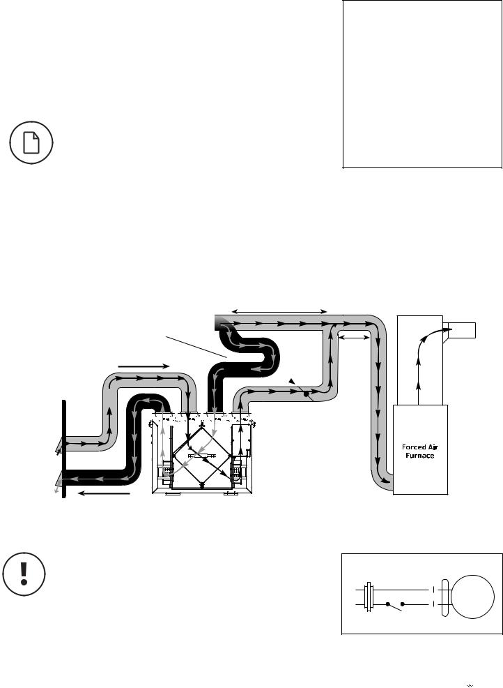
DIRECT CONNECTION of both the HRV SUPPLY AIR STREAM and EXHAUST AIR STREAM to the FURNACE COLD AIR RETURN
SIMPLIFIED INSTALLATION (GOOD) (RETURN/RETURN METHOD) - OPTION 1
1.Furnace blower must operate when ventilation from HRV is required. The
furnace should be set to run continuously or interlocked with HRV.
2.A minimum separation of 1m (3`3’’) is recommended between the two direct connections.
3.In order to prevent exhausting any fresh air, the HRV’s exhaust air connection should be upstream of the HRV’s supply air connection when ducting to the furnace’s cold air return.
4.Due to the difference in pressure between the HRV and the equipment it is being connected to the HRV’s airflow must be balanced on site, using the procedure found in the section “AIRFLOW BALANCING”
HRV/ furnace for Simplified Installation – Option 1
Suggested installation for:
•When bathroom and kitchen already have local exhaust system
•May be suitable for retrofitting
Benefits: Least expensive installation type
1 m (3' 3") min. recommended
Stale air from inside
Fresh air from
outside  Motorized
  Damper
Outside 


 Fresh air to


 living areas
Stale air to
outside * Unit airflow should be balanced while HRV is on “Normal” speed and furnace blower is running.
1 m (3' 3") min. recommended
Cold air return
Fantech heat recovery ventilators (HRV) that use a supply fan shutdown for frost prevention do not include an outdoor air motorized damper. If you are using a simplified installation, i.e. connecting the HRV supply air duct to a furnace's return air duct, the HRV must operate continuously. When the HRV is turned off, no warm exhaust air will flow through the HRV but the furnace's fan will continue to draw in outdoor air directly into the furnace. If it's cold outside, cold air will be introduced, without re-heating, directly into the furnace.
If the HRV is installed such that the homeowner may turn off the HRV during the winter, we recommend installing a motorized damper between the HRV's supply air and the furnace's return air duct that closes when the HRV is not operating. See wiring diagram (figure 1). You may also choose to use a Fantech HRV that uses a recirculation defrost that incorporates an outdoor air damper.
24 VAC Transformer
24V |
|
|
120V |
Damper |
|
Motor |
||
|
||
COM |
NO |
HRV Furnace interlock
See page 16.
Figure 1
*Transformer and Damper motor not included


 fantech
8
Installation examples (Cont'd)
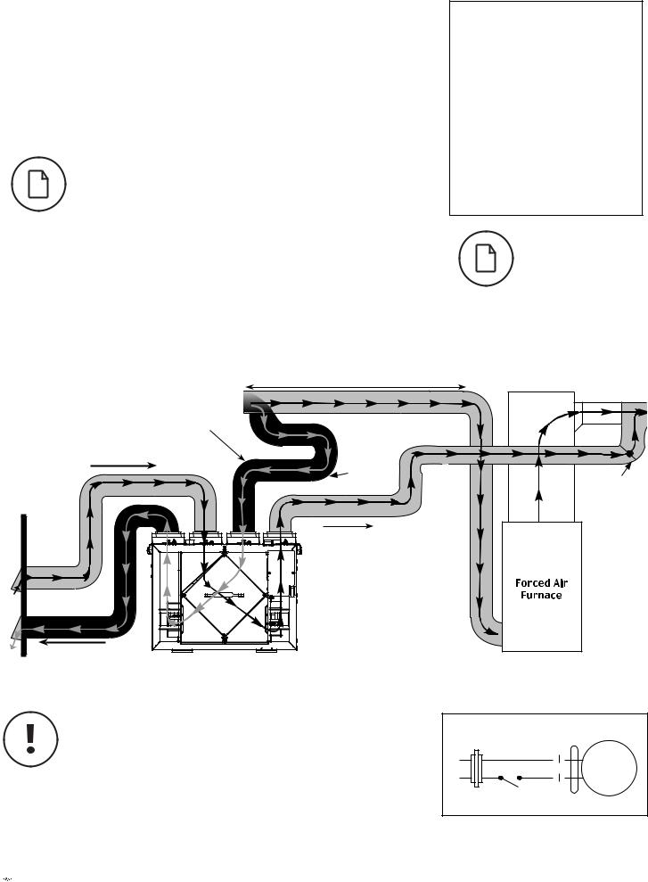
DIRECT CONNECTION of the HRV SUPPLY AIR STREAM to the SUPPLY AIR SIDE on the FURNACE & EXHAUST AIR STREAM to the FURNACE COLD AIR RETURN
SIMPLIFIED INSTALLATION (GOOD)
OPTION 2
1.Furnace blower must operate when ventilation from HRV is required. The furnace should be set to run continuously or interlocked with HRV.
2.Due to the differences in pressure between the HRV and the equipment it is being connected to, the HRV‘s airflow must be balanced on site, using the procedure found section "AIRFLOW BALANCING".
Suggested installation for:
•When bathroom and kitchen already have local exhaust system
•May be suitable for retrofitting
Benefits: Least expensive installation type
In the case of a simplified installation, Option 1 is recommended.
HRV/Furnace ducting for Simplified Installation - Option 2 |
||
* Ductwork layout may differ depend- |
1 m (3' 3") min. recommended |
|
|
||
ing on model |
|
|
|
Air from inside |
|
Fresh air from |
Motorized |
|
outside |
||
Damper |
||
|
||
|
Motorized |
|
Outside |
Damper |
|
|
||
|
Fresh air to living areas |
|
|
Cold air |
|
|
return |
|
Stale air to |
* Unit air flow should be balanced while HRV is on "Normal" speed and |
|
outside |
||
furnace blower is running. |
||
Fantech heat recovery ventilators (HRV) that use a supply fan shutdown for frost prevention do not include an outdoor air motorized damper. If you are using a simplified installation, i.e. connecting the HRV supply air duct to a furnace's return air duct, the HRV must operate continuously. When the HRV is turned off, no warm exhaust air will flow through the HRV but the furnace's fan will continue to draw in outdoor air directly into the furnace. If it's cold outside, cold air will be introduced, without re-heating, directly into the furnace.
If the HRV is installed such that the homeowner may turn off the HRV during the winter, we recommend installing a motorized damper between the HRV's supply air and the furnace's return air duct that closes when the HRV is not operating. See wiring diagram (figure 1). You may also choose to use a Fantech HRV that uses a recirculation defrost that incorporates an outdoor air damper.


 fantech
24 VAC Transformer
24V |
|
|
120V |
Damper |
|
Motor |
||
|
||
COM |
NO |
HRV Furnace interlock
See page 16.
Figure 1
*Transformer and Damper motor not included
EXTERIOR DUCTING INSTALLATION
WEATHERHOOD LOCATION
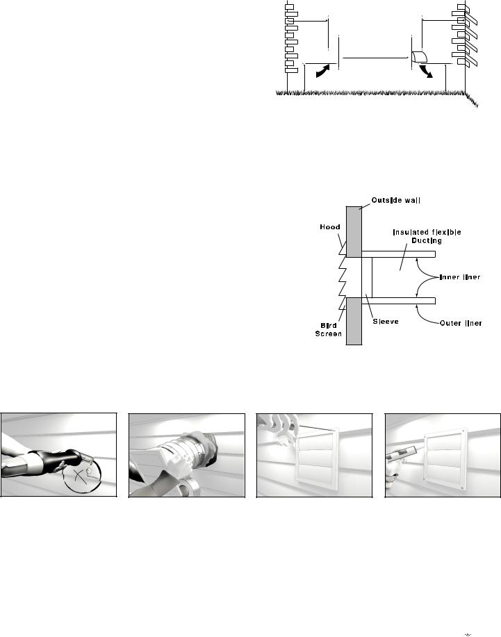
• Decide where your intake and exhaust hoods will be located.
Locating the Intake Weatherhood
•Should be located upstream (if there are prevailing winds) from the exhaust outlet.
•At a minimum of 2m (6’) away from dryer vents and furnace exhaust
(medium or high efficiency furnaces), driveways, oil fill pipes, gas meters, or garbage containers.
•At a minimum height of 460mm (18’’) above the ground, or above the level of expected snow accumulation.
•At a minimum distance of 1m (3’) from the corner of the building.
•Do not locate in the garage, attic, crawl space, or underneath deck.
OUTSIDE CORNER
36" (1m) min.
INTAKE 

18" (460mm) min.
Locating the Exhaust Weatherhood
•At least 460mm (18") above ground or above the depth of expected snow accumulation
•At least 1m (3’) away from the corner of the building
•Not near a gas meter, electric meter or a walkway where fog or ice could create a hazard
•Do not locate in a garage, workshop or other unheated space
INSTALLING THE DUCTING TO THE WEATHERHOODS
A well designed and installed ducting system will allow the HRV to operate at its
maximum efficiency. The inner liner of the flexible insulated duct must be secured to the sleeve of the weatherhood (as close to the outside as possible) and to the appropriate duct connection on the HRV. The insulation should remain full and not crushed. The outer liner, which acts as a vapor barrier, must be completely sealed to the outer wall and the HRV using tape and/or caulking. A good bead of high quality caulking (preferably acoustical sealant) will seal the inner flexible duct to both the HRV duct connection and the weatherhood prior to securing them.
To minimize airflow restriction, the flexible insulated duct that connects the two outside weatherhoods to the HRV should be stretched tightly and be as short as possible.
Twisting or folding the duct will severely restrict airflow.
See “Installation Diagram Examples” for installation examples.
9
INSIDE CORNER
36” (1m) min.
6' (2m) min.
EXHAUST
18" (460mm) min.
STEPS FOR HOOD INSTALLATION:
1Using the duct connection of the outside hood, outline the intake & exhaust holes to be cut. The holes should be slightly larger than the duct connection to allow for the thickness of the insulated flexible duct. Cut a hole for both the intake and exhaust hoods.
2Pull the insulated flexible duct through the opening until it is well extended and straight.
Slide the duct’s inner vinyl sleeve over the hood duct connection and secure. Pull the insulation over the duct and pull the vapor barrier over the sleeve. Secure with appropriate tape or sealant.
3Push the hood into the opening and then attach the hood to the outside wall with mounting screws.
Repeat the installation procedure for both the supply and exhaust hoods.
4Using a caulking gun, seal around both hoods to prevent any leaks.


 fantech
10
INTERIOR DUCTING INSTALLATION
•To maximize airflow through the ductwork system, all ducts should be kept short and have as few bends or elbows as possible.
•45º elbows are preferable to 90º.
•Use “Y“ ducts instead of “T” ducts whenever possible.
•All duct joints must be fastened with screws or duct sealant and wrapped with aluminum foil duct tape to prevent leakage.
•Galvanized ducting from the HRV to the living areas in the house is recommended whenever possible, although flexible ducting can be used in moderation when necessary.
•To avoid possible noise transfer through the ductwork system, a short length (approximately 300mm, 12’’) of nonmetallic flexible insulated duct should be connected between the HRV and the supply/exhaust ductwork system.
•The main supply and return line to/from the HRV must have the same diameter as the duct connection or larger.
•Branch lines to the individual rooms may be as small as 100mm (4’’).
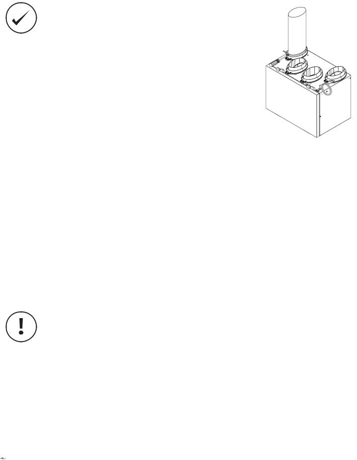
INSTALLING DUCT TO HRV
For flexible duct installation, slide flexible ducting onto duct connection. Then install a cable tie over flexible duct to prevent leakage between the ducting and the duct connection.
In the case of solid ducting, slide duct over duct connection, screw in place and seal.
SUPPLY AIR GRILLES LOCATION
In homes without a forced air furnace, fresh air should be supplied to all habitable rooms, including bedrooms and living areas. It should be supplied from high wall or ceiling locations. Grilles that diffuse the air comfortably are recommended. In homes with a forced air furnace, you may want to connect the HRV to the furnace ductwork (see information below).
EXHAUST AIR GRILLES LOCATION
The stale air exhaust system is used to draw air from the points in the house where the worst air quality problems occur. It is recommended that return air ducts be installed in the bathroom, kitchen, and laundry room. Additional return air ducts from strategic locations may be installed. The furnace return duct may also be used to exhaust from. In this method, the exhaust air is not ducted back from bathrooms, kitchens, etc to the HRV with “dedicated lines”.
As per building codes and installation requirements for combustion appliances:
Air return ducts, or openings for air return, should not be placed in enclosed spaces containing combustion appliances that are subject to spillage.


 fantech

11
DUCTING INSTALLATION EXAMPLES
Fully dedicated system |
Partially dedicated system |
Bedrooms
3m
Fresh Air
Exhaust Air
FEL 4 (4” Miter Elbow)
Exhaust CG 4 (4” Adjustable Grill)
Bathroom
Central Control - optional
Fresh air to living room
|
|
|
|
|
|
|
Supply |
|
|
|
|
|
|
Supply |
|
|
HRV |
|
|
|
|
||||||||||||
|
|
|
|
|
|
|
Exhaust |
|
|
|
|
|
|
Exhaust |
|
|
|
|
|
|
|
|
|
|
|
|
|
|
|
|
|
||
|
|
|
|
|
|
|
|
|
|
|
|
|||||
|
|
|
|
|
|
|
|
|
|
|
|
|
|
|
|
|
|
|
|
|
|
|
|
|
|
|
|
|
|
|
|
|
|
|
|
460 mm |
|
|
|
|
|
|
|
|
||||||
|
|
|
|
|
|
|
|
|
|
|
|
|
|
|
|
|
|
|
|
|
|
|
|
|
|
460 mm |
|
|
|||||
|
|
|
|
|
|
|
|
|
|
|
|
|
|
|
|
|
Simplified installation - Option 1 |
Simplified installation - Option 2 |
|


 fantech
12
HRV INSTALLATION
•Have a nearby power supply (120 volts, 60Hz)
•Choose a location which allows the possibility
of mounting the unit to supporting beams.
•The unit should be level in order to allow proper condensate drainage
•To minimize noise, do not install unit in living area
•Ensure proper drainage
LOCATION
The HRV must be located in a conditioned space where it will be possible to conveniently service the unit. Typically the HRV would be located in the mechanical room or an area close to the outside wall where the weatherhoods will be mounted. If a basement area is not convenient or does not exist, a utility room may be used.
Attic installations are not normally recommended due to:
•The complexity of the installation
•Freezing conditions in the attic
•Difficulty of access for service and cleaning
•No drain access
Connecting appliances to the HRV is not recommended. These include:
•Clothes dryer
•Range top
•Stovetop fan
•Central vacuum system
•Bathroom exhaust fans unless they are specifically designed for this purpose
These appliances may cause lint, dust or grease to collect in the HRV, damaging the unit.
Connecting any of these types of appliances to the HRV will void your warranty.
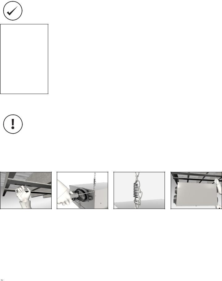
MountingChain mount
1Place fastening hooks on the strapping board or the floor joists.
2Attach a hanging chain (provided) to each 19 mm (3/4") bolt (provided) in the top 4 corners of the unit and tighten.
3Install a spring on each chan. Hook the spring in the links so a loop is
created in the chain. The spring will then support the unit's weight and absorb vibrations.
4Hang the unit by slipping a link onto the hanging hooks, making sure the unit is level.


 fantech
 Loading...