


DBF110 DRYER EXHAUST BOOSTER SYSTEM
INSTALLATION INSTRUCTIONS
DISPOSITIF DBF110 D’AMPLIFICATION DU SYSTÈME DE VENTILATION DES SÉCHOIRS À LINGE INSTRUCTIONS D’INSTALLATION
SISTEMA DE REFUERZO DE ESCAPE DE LA SECADORA DBF110
INSTRUCCIONES DE INSTALACION
DBF110 DRYER EXHAUST BOOSTER SYSTEM INSTALLATION INSTRUCTIONS
DBF110 Includes:
1 DBF 110 Dryer Booster Fan
1 Fan Mounting Bracket and Hardware
1 Small Wall Sign Indicating Proper Operating Procedure
Important Notice
Read and Save these instructions for future reference.
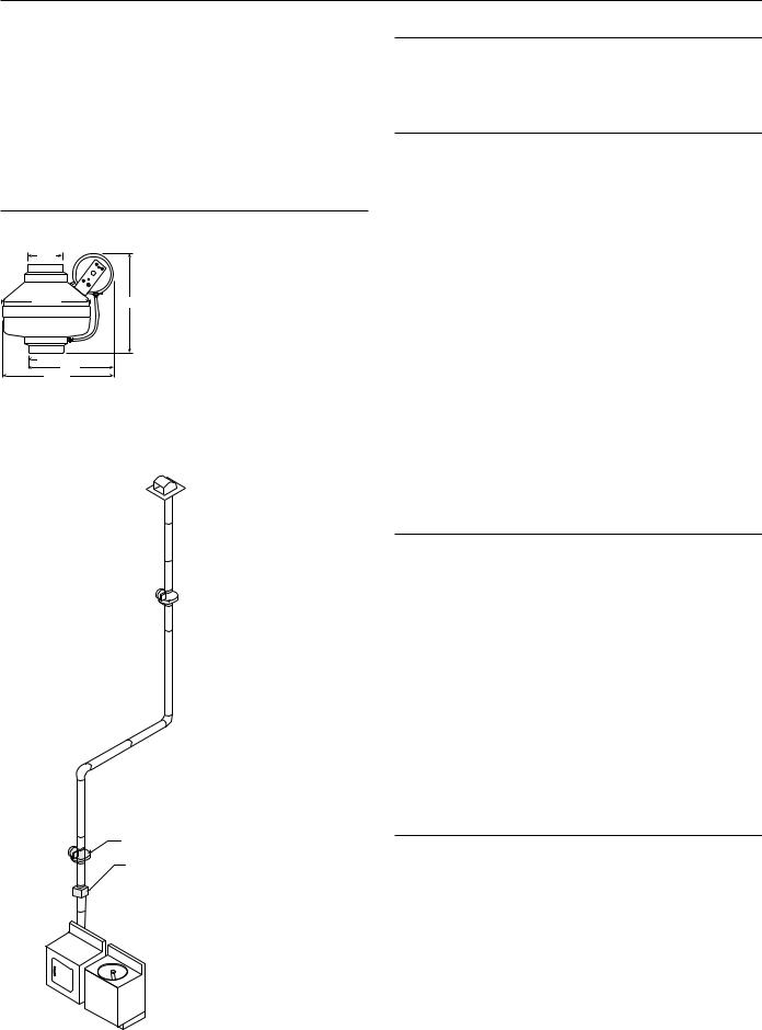
Dimensional Data
4″
9¹| ″ |
11¹| ″ |
4″ 

9¹| ″
12¹| ″
(DBF110)
Installation Guidelines
Please note: DBF 110 fans are not explosion proof. Do not use the fans if a potentially explosive situation may exist.
DO NOT USE with heated air in excess 140˚F (60˚C).
Fan and Switch Mounting
The recommended location of the booster fan is a minimum of 15 linear (not equivalent) feet of duct from the dryer outlet. If the fan is mounted closer than the recommended 15 feet, it may develop enough pressure to lift wet lint into the fan impeller resulting in excessive lint loading in the fan. The best location for the fan to be mounted is as close as possible to the termination of the duct work. (Exception: If a secondary lint filter is installed between the dryer and the booster fan, the booster fan may be mounted within the minimum distance otherwise recommended (See illustration to left). An NB mounting bracket attached to a rafter or joist should be used to stabilize the fan. Although not recommended, a vertical rigid duct may support the fan if the duct is securely stabilized. (Consult local codes prior to supporting the fan in the duct alone.) Duct work should be attached to the inlet and outlet of the fan by means of FC vibration isolation clamps (not included) or duct tape. The duct connection should be properly sealed to prevent leakage and loss of fan performance. Flex duct connections between the dryer duct connection and exhaust duct should be stretched as smooth as possible.
Illustration 1 |
|
Calculating Duct Run |
|
To calculate the length of your planned duct run, measure from the dryer |
|
|
|
to external venting point in roof or wall. For each bend or elbow add 5-7 |
|
||
|
|
feet to your total duct run calculations. The DBF4XL can be used on runs |
|
|
up to 108 feet. |
DBF110
Alternative Location
Secondary Lint Trap
Pressure Sensor Switch Operation
Fantech’s DBF110 is equipped with Fantech's Patented DB10 pressure switch. The DB10 is a positive pressure sensing switch which recognizes dryer operation and activates the booster fan from an independent electrical circuit. This eliminates connections through the dryer circuit which may void the manufacturers’ warranty as well as manual systems which require the attention of the operator or costly current/temperature sensing systems.
The electricity to the booster fan is connected in series through a normally open terminal on the switch. A pressure tap is connected to a fitting on the side of the switch. When the dryer begins operation, positive pressure in the duct causes the switch diaphragm to expand, closing the circuit to the booster fan. An integral delay-on-break timer in the switch will cycle the fan on for intervals of 10 minutes. This will continue until the dryer has stopped and the timer delay period has lapsed. Drying cycles, the booster fan, the delay timer and the pressure switch are not adversely affected by the starting/stopping intervals.
Fan Installation
Step 1. Selecting Fan Location
Fan must be mounted a minimum of 15 feet from the dryer outlet. If the fan is mounted closer than the recommended 15 feet, it may develop enough pressure to lift wet lint into the fan impeller resulting in excessive lint loading in the fan. (Exception: If a secondary lint filter is installed between the dryer and the booster fan, the booster fan may be mounted within the minimum distance otherwise recommended (See illustration to left). The best location for the fan to be mounted, in any application, is as close as possible to the termination of the duct work. In order to perform recommended maintenance, fan location should allow sufficient access for service. Refer to dimensional drawings shown above.

Step 2. Mount Bracket
Using the wood screws provided, attach the mounting bracket to a support beam at the selected location. Bracket is provided with grommets in order to isolate any vibration and prevent the transmission of sound through the structure. Be careful not to overtighten. Fan mounting can be in any angle (see ill. 2), however, vertical mounting is recommended to reduce condensation buildup in the fan. If a horizontal installation is
necessary and condensation buildup may pose a problem, a ¹|" hole drilled in the bottom of the housing (along with an NPT insert [by others] and drain tubing) will allow condensation to drain.
Step 3. Mount Fan
For proper operation, the switch diaphragm must be positioned vertically. (Illustrations below show diaphragm position for horizontal, vertical and ducts installed at an angle.) Wiring box should be positioned for easy access. Attach fan to the mounting bracket with the self tapping screws provided. Care should be taken not to strip the plastic housing.
Although screw pilot holes are not required, ³|" (or smaller) pilot holes are recommended.
NOTE: Steps 2 & 3 may be reversed.
Electrical Connection
DO NOT CONNECT POWER SUPPLY UNTIL FAN IS COMPLETELY INSTALLED. MAKE SURE ELECTRICAL SERVICE TO THE FAN IS LOCKED IN "OFF" POSITION.
1.This unit has rotating parts and safety precautions should be exercised during installation, operation and maintenance.
2.CAUTION: "For General Ventilation Use Only. Do Not Use To Exhaust Hazardous Or Explosive Materials And Vapors."
3.WARNING: TO REDUCE THE RISK OF FIRE, ELECTRIC SHOCK, OR INJURY TO PERSONS - OBSERVE THE FOLLOWING:
a.Use this unit only in the manner intended by the manufacturer. If you have questions, contact the factory.
b.Before servicing or cleaning, switch power off at service panel and lock service panel to prevent fan from being switched on accidentally. When the service disconnecting means cannot be locked, securely fasten a prominent warning device, such as a tag, to the service panel.
c.Installation work and electrical wiring must be done by qualified person(s) in accordance with all applicable codes and standards, including fire-rated construction.
d.The combustion airflow needed for safe operation of fuel burning equipment may be affected by this unit's operation. Follow the heating equipment manufacturer's guidelines and safety standards such as those published by the National Fire Protection Association (NFPA), the American Society of Heating, Refrigeration, and Air Conditioning Engineers (ASHRAE) and the local code authorities.
e.When cutting or drilling into wall or ceiling, do not damage electrical wires or other hidden utilities.
f.Ducted fans must always be vented to the outdoors.
g.Install fan at least five feet above the floor.
4.WARNING! Check voltage at the fan to see if it corresponds to the motor nameplate.
GUARDS MUST BE INSTALLED WHEN FAN IS WITHIN REACH OF PERSONNEL OR WITHIN SEVEN (7) FEET OF WORKING LEVEL OR WHEN DEEMED ADVISABLE FOR SAFETY.
Illustration 2
Correct Mounting of Diaphragm Switch
Horizontal |
Vertical |
Angled |
|
|
Switch mounted |
|
|
properly |
|
|
above and |
|
|
below |
Switch mounted |
|
duct. |
|
|
|
properly above |
|
|
duct. |
|
|
Incorrect Mounting of Diaphragm Switch
Illustration 3
Attach Mounting Bracket to |
Attach Fan to Mounting |
stud using screws provided. |
Bracket using screws provided. |
Illustration 4
Switch Circuit
Electrical Supply from
Breaker Panel
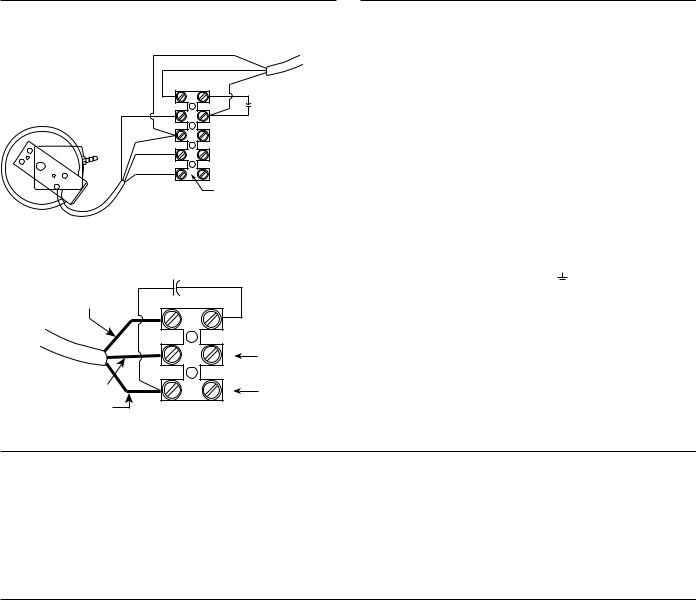
Illustration 5
DBF110 Wiring – Fan and Pressure Switch
Blue |
Power |
Brown |
to Fan |
Black |
|
Red |
Capacitor |
||
|
|
||
White |
Neutral |
|
|
Black |
|
||
115V Line (Supply) |
Electrical supply, 115V |
||
|
|||
Green |
Ground |
|
|
|
|
||
Terminal block in fan wiring box
Fan Only Wiring (Reference for Troubleshooting Step 8c)
Capacitor
Brown (Z2)
Motor
Leads
N |
Neutral side of |
|
115V supply |
||
|
||
Blue (U2) |
Line side of |
|
L |
||
Black (TK) |
115V supply |
Wiring Procedure
Please Note: The fan motor, capacitor and pressure switch connections are pre-wired from the factory.
Step 1.
Remove the screws securing the terminal box cover plate located on the side of the fan. All fan motor connections are prewired to an elec-
trical terminal strip. A ³|" romex type cable restraint connector will be needed to secure the wiring through the knockout provided on the side of the terminal box.
Step 2.
Bring incoming electrical service through the romex connector and the fan knockout. Be sure to place the connector nut over the wiring coming into the terminal box. There are three open ports on the terminal strip. Using a small regular screwdriver, tighten the Neutral (White) wire of the incoming supply under the open terminal labeled "N". Tighten the Line (Black) wire of the incoming supply under the open terminal labeled "L". Tighten the Ground (Green) wire of the incoming supply under the open terminal marked " ". For reference, a wiring diagram is included on the inside of the terminal box lid.
Step 3.
Secure the romex connector. Secure the incoming supply with the romex connector. Replace the fan terminal box cover.
Warranty and Maintenance
Recommended Maintenance
1.Since fan bearings are sealed and provided with an internal lubricating material, no additional lubrication is necessary.
2.Fan impeller may accumulate lint. Periodic inspection, based upon dryer usage, should be performed to ensure that the fan impeller is not obstructed or loaded with lint. Under normal conditions, fan
Troubleshooting
should be inspected a minimum of every Six (6) Months. Note: Excessive booster fan noise or vibration may be an indication of lint buildup on the impeller. To inspect and clean the impeller:
a.Disconnect the incoming power supply at the source.
b.Remove the duct from the fan inlet and remove any lint buildup on the impeller.
c.Reconnect the duct to the fan. Turn power supply on.
Important Notice: Prior to performing Steps 1 - 4, be certain that the electrical supply to the fan/switch is turned off.
If fan fails to start when the dryer cycle begins, please follow the procedure listed below:
1.Check the incoming supply for proper voltage.
2.Consult schematic shown above (also included on inside of fan wiring terminal lid) to ensure proper connection.
3.If possible, use a meter to test for continuity across the fan motor leads. In order to do this, the capacitor and pressure switch must be disconnected (do not test the capacitor - it will not meter continuity). If motor leads show continuity, rewire the fan, capacitor and pressure switch.
4.Turn on the electrical supply and restart the dryer cycle. Check to be certain that fan starts.
If fan still fails to start after performing Steps 1 – 4, continue following the procedure as listed below:
5.Verify that the pressure switch diaphragm is vertical as shown in Illustration 2 of these instructions. If the diaphragm is not vertical, reposition the pressure switch and check for fan operation against another dryer cycle.
6.Verify that the tubing is not crimped and that the tubing connector nipples are not obstructed.
7.If switch diaphragm is vertical and fan still fails to start, with the electrical supply on:
a.Remove the tubing from the nipple on the fan and blow gently into the tubing;
b.If fan starts, consult Fantech for additional technical support.
8.If fan fails to start after blowing into the tubing:
a.Disconnect incoming power supply at the source.
b.Remove the pressure switch leads from the wiring terminal block
c.Connect the incoming power supply directly to the fan motor as shown in "FR110 Wiring" diagram below.
d.Turn on power to fan.
9.If fan fails to start, please consult Fantech for additional technical support.
 Loading...