


Installation and Maintenance Manual Manuel pour l'Installation et l'Entretien Manual de Instalación y Mantenimiento
Item #: 412889 Rev Date: 110613
PB Series
Premium Bath Fans
(single grille unit 4" duct PB110*, PB110F, PB110F-ES*, PB110H,; single and dual grille units 6" duct PB190*, PB270-2*, PB270F-2, PB270F-2ES*, PB270H-2, PB370-2*, PB270FV-2, PB270FV-2ES*, PB270HV-2)
Ventilareurs pour salle de bains premium
(grille simple conduit de 4 po PB110*, PB110F, PB110F-ES*, PB110H; grille simple et double conduit de 6 po PB190*, PB270-2, PB270F-2, PB270F-2ES*, PB270H-2, PB370-2*, PB270FV-2, PB270FV-2ES*, PB270HV-2)
Ventiladores Para Baño Premium
(unidades de Reja Solas 4" conducto PB110*, PB110F, PB110F-ES*, PB110H, unidades de reja solas y duales 6" Conducto PB190*, PB270-2, PB270F-2, PB270F-2ES*, PB270H-2, PB370-2*, PB270FV-2, PB270FV-2ES*, PB270HV-2)
United States
10048 Industrial Blvd., Lenexa, KS, 66215
Tel.: 800.747.1762 • Fax: 800.487.9915
Canada
To ensure quiet operation of ENERGY STAR® qualified inline and remote fans, each fans shall be installed using sounds attenuation techniques appropriate for the installation. For bathroom and general ventilation applications, at least 8 feet of insulated duct shall be installed between the exhaust or supply grilles(s) and the fan. For kitchen range hood remote ventilation applications, where metal duct is generally required by code, a metal sound attenuator shall be installed between the range hood and the fan.
Pour assurer un fonctionnement silencieux des ventilateurs et des ventilateurs
à distance qualifiés ENERGY STAR®, chaque ventilateurs doit être installé en utilisant des techniques d'atténuation du son appropriées pour l'installation. Pour les applications de salles de bain et les applications de ventilation générales, au moins 8 pieds de conduits flexible isolé doivent être installées entre les grilles d'évacuation et d'approvisionnement du ventilateur. Pour les applications de hotte de cuisinière à distance, où un conduit en métal est généralement requis par le code du bâtiment, un atténuateur acoustique en métal doit être installé entre la hotte et
le ventilateur.
*
Para asegurar una operación silenciosa de los ventiladores en línea certificados ENERGY STAR, cada ventilador debe
instalarse utilizando técnicas de atenuación de sonido apropiadas para cada caso. Para baños y aplicaciones comunes de ventilación se recomienda instalar por lo menos 8’ de ducto flexible con aislamiento entre la rejilla de expulsión y/o inyección
y el ventilador. Para campanas de cocina con un ventilador de extracción remoto, done se usa por código ducto rígido, se recomienda instalar un atenuador de sonido entre la campana y el ventilador.
50 Kanalflakt Way, Bouctouche, NB, E4S 3M5
Tel.: 800.565.3548 • Fax: 877.747.8116
*These products are ENERGY STAR® Qualified.


 fantech
2
|
|
|
|
|
|
|
|
|
|
|
|
|
|
|
|
|
|
|
|
|
Note |
Warning / |
Information |
Technical |
Practical tip |
||
|
|
|
Important |
|
information |
|
|
|
|
note |
|
|
|
Before installation, servicing or cleaning unit, switch power off at
service panel and lock the service disconnect to prevent power from being switched on accidentally. When the service disconnect cannot be locked, securely fasten a prominent warning device, such as a tag, to the service panel.
1.The compactness and adaptability of the FG Series fans permit easy installation. The fans are shipped fully assembled and can be
mounted at any angle. For various mounting, see figures on the following page.
2.Because this unit has rotating parts, safety precautions should be exercised during all phases of installation, operation and maintenance.
3.CAUTION: “For General Ventilation Use Only. Do Not Use To Exhaust Hazardous Or Explosive Material and Vapors.”
4.Remove unit from package and inspect within
15days after receipt. If damaged, report damage to carrier. Do Not operate this unit with visible damage to the blower or impeller
assembly.
5.CAUTION: “This unit has an unguarded impeller. Do not use in locations readily accessible to people or animals.”
WEAR HAND PROTECTION AND STAY CLEAR OF SHARP EDGES!
6.Screen guards must be installed within reach of personnel, within (7) feet of the working area, or when advisable for safety.
7.CAUTION: Bulb used in fluorescent models not dimmable.
8.CAUTION: Use only Fantech Fluorescent bulb (model PBB14 and PBB14-ES) and PAR16 / MR16 GU10 50W max. halogen bulbs (model PBB50).
9.PLEASE read the entire manual before installing.


 fantech
Avant l’installation, le service ou le nettoyage, coupez l’électricité au compteur électrique et fermez-le à clé afin d’éviter que l’électricité ne soit retranchée accidentellement. Quand le tableau de contrôle ne peut pas être fermer à clé, afficher un dispositif d’avertissement bien en vue, comme une étiquette par exemple placée sur le tableau électrique.
1.La compacité et l’adaptabilité des ventilateurs FG permettent une installation facile. Les ventilateurs sont envoyés complètement assemblés et peuvent être montés sur N’importe quel angle. Pour les montages différents veuillez voir les pages suivantes.
2.Cet appareil contient des parties rotatives, des mesures de sécurités doivent être observées lors de l’installation et l’entretien.
3.PRECAUTION: A utiliser strictement pour une ventilation normale. A NE PAS UTILISER POUR évacuer des vapeurs de matériaux dangereux ou explosifs.
4.Retirer l’appareil de son emballage et inspectez-le dans les 15 jours qui suivent sa réception. S’il est endommagé, rapporter les dommages à l’envoyeur. Ne Pas utilisez cet appareil avec un dommage apparent sur le souffleur ou le système de ventilation.
5.PRECAUTION: “Cet appareil a un ventilateur de projection non protégé. Ne pas l’utiliser dans un endroit où il peut êtreaccessible aux personnes ou aux animaux.”
PORTEZ DES GANTS ET ESSAYER D’EVITER LES BORDS COUPANTS!
6.Un écran de protection doit être installé hors d’atteinte du per sonnel à 7 feet (2 mètres environ) de la zone de travail oudans des limites raisonnables de sécurité.
7.PRECAUTION: Les ampoules utilisées dans les modéles fluorescents ne sont pas réglables.
8.Attention: Utilisez seulement les ampoules «PBB14 et PBB14-ES» pour les modèles fluorescents et les ampoules PAR16/MR16 BU10 50W/ pour les modèles halogènes (Modèle PBB50).
9.VEUILLEZ, lire ce manuel en entier avant de l’installer.
Antes de instalar la unidad, hacerle mantenimiento o limpiarla, desconecte la alimentación en el tablero de servicio y cierre con llave el interruptor del circuito para impedir la reactivación accidental. De no poder cerrarse el interruptor con llave, aplíquele al tablero una etiqueta o dispositivo de advertencia bien visible.
1.El diseño compacto y adaptable de los ventiladores de la Serie FG facilita la instalación. Los ventiladores se despachan totalmente ensamblados, y se pueden montar a cualquier ángulo. Vea en la página siguiente los distintos montajes disponibles.
2.Debido a que esta unidad tiene piezas rotativas, hay que tomar medidas de precaución a toda hora durante la instalación, operación y mantenimiento de la misma.
3.PRECAUCION: “Sólo para Empleo en Ventilación General. No Usar Como Extractor de Material y Vapores Peligrosos o Explosivos.”
4.Desempaque la unidad e inspecciónela antes de los 15 días de recibida. Si presenta daños, informe al transportista. No opere esta unidad si presenta daños visibles al conjunto de ventilador o impulsor.
5.PRECAUCION: “Esta unidad contiene un impulsor expuesto.No la utilice en sitios de fácil acceso por personas o animales.”
¡USE PROTECCION PARA LAS MANOS Y CUIDESE DE CANTOS O BORDES AFILADOS!
6.Hay que instalar rejillas de guarda al alcance del personal, a menos de (7) pies del sitio de la obra o donde quiera que hagan falta para protección.
7.PRECAUCIÓN: La bombilla utilizada en los modelos fluorescentes no es atenuable.
8.PRECAUCIÓN: Utilice solamente focos fluorescentes Fantech (modelo PBB14 y PBB14ES) y focos de halogeno PAR16 / MR16 GU10 de un max de 50W (modelo PBB50)
9.FAVOR leer este manual por completo antes de proceder a la instalación.

3
Warnings |
Advertissements |
Advertencias |
DO NOT CONNECT POWER SUPPLY until fan is completely installed. Make sure electrical service to the fan is in the locked “OFF” position.
1.All fans are suitable for use with solid-state speed control. Three phase units must be wired through a motor contactor.
2.WARNING! TO REDUCE THE RISK OF FIRE, ELECTRIC SHOCK, OR INJURY TO PERSONS - OBSERVE THE FOLLOWING:
a. Use this unit in the manner intended by the manufacturer. If you have any questions, contact your manufacturer’s representative or contact us directly.
b. CAUTION: Before installation, servicing or cleaning unit, switch power off at the service panel and lock the service disconnect to prevent power from being switched on accidentally. When the service disconnect cannot be locked, securely fasten a prominent warning device, such as tag, to the panel.
c. Installation work and electrical wiring must be done by qualified person(s) in accordance with all applicable codes and
standards, including fire-rated construction. d. Sufficient air is needed for proper
combustion and exhausting of gases through the flue (chimney) of fuel burning equipment to prevent back drafting. Follow the heating equipment manufacturer’s guideline and safety standards such as those published by the National Fire Association (NFPA), and the American Society for Heating, Refrigeration and Air-Conditioning Engineers (ASHRAE), and the local code authorities.
e. When cutting or drilling into wall and ceiling, do not damage electrical wiring and other hidden utilities.
f. Ducted fans must always be vented to the outdoors.
g. If this unit is to be installed over a tub or shower, it must be marked as appropriate for the application and be connected to a GFCI (Ground Fault Circuit Interrupter) - protected branch circuit.
h. NEVER place a switch where it can be reached from a tub or shower.
3.WARNING! Check voltage at the fan to see if it corresponds to the motor name plate.
NE PAS BRANCHER l’électricité jusqu’à ce que le ventilateur soit complètement installé. Veillez à ce que le tableau électrique du ventilateur soit verrouillé (“OFF”).
1.Tous les ventilateurs sont faits pour être utilisés avec une commande de vitesse. Les appareils avec trois vitesses doivent être reliés à un interrupteur et un disjoncteur.
2.AVERTISSEMENTS POUR RÉDUIRE LES RISQUES D’INCENDIE, DE DECHARGE ELECTRIQUE OU RISQUE DE BLESSURES. SUIVEZ LES CONSEILS SUIVANTS:
a. Cet appareil ne doit pas être utilisé pour une autre fonction que celle prévue par son fabricant. Si vous avez des questions, contactez les représentants de vos fabricants ou contactez-nous directement.
b. ATTENTION: Avant l’installation, le service ou le nettoyage de l’appareil, fermer l’électri-
cité et fermer à clé le compteur électrique afin d’éviter que l’électricité ne soit retranchée accidentellement. Si le compteur ne peut pas être fermé à clé, attachez au compteur un dispositif de sécurité comme par exemple une étiquette.
c. L’installation de l’électricité doit être faite par une personne qualifiée en accord avec les codes applicables et les règles pour la construction anti-feu.
d. La circulation de l’air est nécessaire pour
une bonne combustion et pour l’aspiration des gazs dans la cheminée afin d’éviter des refoulements. Suivez le guide de chauffage du fabriquant ainsi que les règles de sécurités comme celles qui sont éditées par l’Association Nationale des Sapeurs Pompiers (NFPA) et l ‘Association américaine des Ingénieurs pour le chauffage et l’air conditionné (ASHRAE) ainsi que celles des autorités locales.
e. Lorsque vous coupez ou percez le mur et le plafond faites attention de ne pas endommager les câbles électriques des autres appareils utilitaires.
f. Le ventilateur caréné doit toujours être branché sur l’extérieur.
g. Si l’appareil doit être installé au-dessus d’une baignoire ou d’une douche, il doit être signalé comme tel pour son utilisation et l’installation d’une prise de terre est nécessaire.
h. NE JAMAIS placer près de la baignoire ou de la douche un interrupteur à porté de la main.
3.ATTENTION : Vérifier le voltage afin de voir s’il correspond à celui indiqué sur la plaque du moteur.
NO CONECTE LA ALIMENTACION hasta tanto el ventilador quede completamente instalado. Cerciórese de que el servicio eléctrico al ventilador quede asegurado en la posición “OFF” (desactivado).
1.Todos los ventiladores vienen preparados para controlarse mediante controles de estado sólido. Las unidades trifásicas tienen que cablearse a través de un contactor de motores.
2.ADVERTENCIA: PARA REDUCIR EL RIESGO DE INCENDIO, CONMOCION ELECTRICA O LESIONES A PERSONAS, OBSERVE LO SIGUIENTE:
a. Sólo utilice esta unidad de la manera dispuesta por el fabricante. Si tiene cualquier pregunta, diríjase al representante del fabricante, o bien a nosotros directamente.
b. PRECAUCION: Antes de la instalación, mantenimiento o limpieza de la unidad, desconecte la alimentación en el tablero de servicio y cierre con llave el interruptor del circuito para impedir la reactivación accidental. De no poder cerrarse el interruptor con llave, aplíquele al tablero una etiqueta o dispositivo de advertencia bien visible.
c. Los trabajos de instalación y cableado eléctrico tienen que ser realizados por personal calificado conforme todos los códigos y normas del caso, incluso el código de incendio en la construcción.
d. La debida combustión y extracción de gases a través de la chimenea de equipos quemadores de combustibles, requiere de una cantidad adecuada de aire que impida el contratiro. Siga las pautas y normas de
seguridad del fabricante, tales como publica la National Fire Association (NFPA) (Asociación Nacional de Incendios) y la American Society for Heating Refrigeration and Air-conditioning Engineers (ASHRAE), así como las de las autoridades locales del código.
e. Al cortar o perforar paredes y cielos rasos, tenga cuidado de no dañar el cableado eléctrico u otros servicios públicos ocultos.
f. Los ventiladores montados en conductos siempre deben contar con respiraderos al exterior.
g. Si esta unidad ha de instalarse por encima de una bañera o ducha, tiene que venir marcada como tal par dicha aplicación y conectarse a un circuito protector interruptor de circuitos de tierra falla.
h. JAMAS coloque un interruptor al alcance de una bañera o ducha.
3.¡ADVERTENCIA! Revise el voltaje entrante al ventilador para constatar que corresponda al que indica la placa de fábrica.


 fantech
4
Installating Fan and Bracket
1. Before selecting mounting location for fan, consider the following:
a)Mounting the fan as far as possible from the intake point will assure quiet operation. A minimum of 8’ of insulated flexible duct is recommended between exhaust grille and fan.
b)Place fan where it can be easily accessed for service.
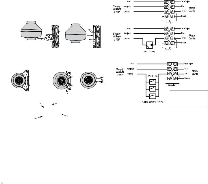
2.Attach the mounting bracket to a support beam with wood screws provided. Fan can be mounted at any point along the duct and at any angle. Vertical mounting is recommended to reduce condensation in the fan. For horizontally mounting, either wrap insulation around the fan or drill a 1 1/4" hole in the bottom of the housing. Add NPT insert and drain tube (purchased separately) for drainage of condensation.
3.For PB Series fans, if bracket is used to mount fan, refer to illustration 1. If suspending fan with hanger straps, refer to illustration 2.
4.Connect duct to inlet and outlet of fan using plastic ties or duct tape (purchased separately). When using insulated flexible duct, the inner vinyl core should be clamped or taped to the inlet and outlet and the vapor barrier surrounding the insulation should be duct taped to the fan housing.
Note: Steps 2 & 3 may be reversed.
Fantech recommends insulated flexible duct for all bathroom exhaust applications.
Illustration 1
• PB110 |
• PB370-2 |
• PB110F(-ES) |
|
• PB110H |
|
• PB190 |
|
• PB270-2 |
|
• PB270F-2(-ES) |
|
• PB270H-2 |
|
•PB270FV-2 (-ES)
•PB270HV-2
Fan bracket should be installed, then fan mounted directly to bracket using sheet metal screws.
Mounting Bracket & Screw Locations for FG
• PB110 |
• PB190 |
• PB370-2 |
• PB110F(-ES) |
• PB270-2 |
|
• PB110H |
• PB270F-2(-ES) |
|
 • PB270H-2
• PB270FV-2(-ES)
• PB270HV-2
Illustration 2
Clamp Fastener |
Duct Fan |
Fans may be suspended |
|
without special |
|
mounting brackets. |
Spiral duct |
|
|
Vibration absorbing material |
|
Flexible Duct Installation Hints
Fantech strongly recommends the use of flexible insulated duct where ducting passes through unconditioned space or where noise is a factor. Check local code requirements before installing. Failure to use insulated flexible duct could result in excessive condensation buildup within the duct, and undesirable sound levels within the room.
A minimum of 8' of insulated flexible duct is recommended between
the fan and any inlet grille. Duct should be stretched as tight and straight as possible. Failure to do so could result in dramatic loss of system performance. Connect flex duct to the fan with plastic zip ties or duct tape. Connections should be airtight as possible for maximize performance.


 fantech
Electrical Connection
1.Remove the screws securing the terminal box cover located on the fan motor mounting bracket. All fan motor and capacitor connections are prewired to an electrical terminal strip. A 3/8" romex type cable restraint connector will be needed to secure the wiring through the knockout on the side of the terminal box.
2.Bring incoming electrical service through the romex connector and the fan electrical service opening. Be sure to place the connector nut over the wiring coming into the terminal box. There are two open ports on the terminal strip. Using a small regular screwdriver, tighten the neutral (white) wire of the incoming supply under the open terminal strip port labeled “N”. Tighten the line (black) wire of the incoming supply under the open terminal strip port labeled “L” to the ground connection on the terminal block.
3.Secure the romex connector. Secure the incoming supply with the romex connector. Place the capacitor back into the terminal box. Replace the fan terminal box cover. All fan motor and capacitor connections have been prewired from the factory. No additional fan wiring is necessary.
Wiring Diagrams
Without Motor Speed Controller
With Motor Speed Controller
Multiple Location Switching Wiring Diagram
WARNING
Maximum torque that can be applied to the terminal block screws is 0.79 Nm (7 lb-in).
Troubleshooting
If fan fails to operate, please check the following:
1.Consult wiring diagrams (above) to ensure proper connection.
2.Check motor lead wiring, capacitor leads and incoming supply leads to insure definite contact.
3.If possible, use a meter to test for continuity across the fan motor leads. In order to do this, the capacitor must be disconnected (do not test the capacitor - it will not meter continuity). If motor leads show continuity, consult factory for a replacement capacitor.
Maintenance Instructions
Since fan bearings are sealed and provided with an internal lubricating material, no additional lubrication is necessary.

Installation of Ceiling Grille Housing With or Without Light
1. Plan Location of Inlet Grilles
Based on the bathroom layout and fixtures, plan the location of the ceiling grilles for the most effective ventilation.
2. Securing the Housing to the Ceiling Joists
NEW CONSTRUCTION
Mount housing directly to the ceiling joist using screws and keyhole slots. Locator tabs on housing should be flush with the bottom edge of the ceiling joist for correct positioning of the unit once drywall is installed (Figure 1).
OR
Use the hanger bars to suspend the housing between ceiling joists. For correct positioning, hanger bars should be positioned 3/16" up from the bottom edge of the ceiling joist on models with 4" duct connection and 15/32" up from bottom edge of joist on models with 6" duct connection. On models with 4" duct, tighten anti-slide screws to keep hanger bars in place. (Figure 2).
Note: Hanger bars on units with 4" duct connection can be used on ceiling joists up to 24" on center. Hanger bars on units with 6" duct connection span ceiling joists up to 16" on center.
Note: If drywall or ceiling material is thicker than 5/8" the locator tabs may be removed to allow the grille collar to be flush with the finished ceiling material. When ceiling drywall is being installed, cut hole for ceiling grille.
EXISTING CONSTRUCTION OR WHEN DRYWALL IS IN PLACE.
Cut a 6" round hole for the ceiling grille only and install the housing from the attic (Figure 3). Place the housing against the ceiling joist using the locator tabs to determine the correct position (Figure 1) or align it using the hanger bars (Figure 2). Punch out the keyhole knockouts (if using) and the electrical knockout if needed. To complete installation for Bath Fan models with lights, continue with steps 3 through 5. For models without lights, skip to steps 4 and 5.
3. Make Electrical Connections to the Ceiling Grille Housing.
Remove the electrical cover inside the steel housing using a screwdriver. Connect power by following wiring diagram (Figure 5) and following local or National Electrical Codes. Replace the electrical cover.
4. Connect the Fan to the Ceiling Grille Housing(s).
Install appropriate diameter duct from the fan to the ceiling grille housing. (Insulated flexible duct is recommended for all Fantech bathroom exhaust applications for quieter operation.) For dual grille models, install duct between fan and wye adapter* (included). Then, attach duct to each leg of the wye and to each ceiling grille housing. Secure duct in place and seal. If using insulated flexible duct, seal the inner liner to the duct connector then seal the outer shell over the top of the inner liner. Do not leave the insulation material exposed.
5. Installing the Bulb.
Install the bulb by gently inserting it into the socket in the grille housing. Install the grille by pushing it firmly into the steel collar until it is shouldered by the ceiling drywall (Figure 3).
Repeat steps 1 through 5 for each additional ceiling grille housing being installed.
Additional steps required when installing a fluorescent modelS PB110F, PB270F-2 or PB270FV-2 over a tub or shower (Figure 4)
1.Place ring 1 on on socket legs first.
2.Screw metal shield in place over socket.
3.Add rubber gasket
4.Secure ring 2 to socket. Click indicates a secure installation.
5
Figure 1
Postion Locator Tabs  flush with bottom
edge of joist
Figure 2
Housings with 4" duct: 3/16" from bottom edge of joist.
Housings with 6" duct: 15/32"
Figure 3
Grille 
Fluorescent lamp
Figure 5
Anti-slide locking screw on models with 4" duct.
Figure 4
Ring 2
Shield |
Gasket |
|
Screw

 Ring 1
Socket
Electrical
*For most efficient operation wye adapter should be positioned the equivalent of three duct diameters away from the fan inlet.


 fantech
 Loading...