


Owner’s Manual
Read and Save These Instructions Lisez et conservez ces instructions Lea y guarde estas instrucciones
Industrial Dehumidifier Déshumidificateur industriel Deshumidificador industrial
Models / Modèles / Modelos
EDP150LR
EDP180CR
EDP190LR
EDP250CR
OPERATION AND MAINTENANCE MANUAL

Industrial Dehumidifier
 WARNING
Electrical Shock Hazard Plug into a grounded 3 prong outlet.
Do not remove ground prong. Do not use an adapter.
Do not use an extension cord.
Failure to follow these instructions can result in death, fire, or electrical shock.
Electrical Requirements
For 115V operation, a common grounded outlet on a 15 amp circuit is required. If used in a wet area, a ground fault interrupter (GFI) is required.
Built in Electrical Safety
For your safety and protection this appliance is manufactured with a grounded plug on its power cord. The power cord must be plugged into a properly grounded receptacle. If a grounded receptacle does not exist, have one installed by a certified electrician. Do not cut or remove the grounding prong on the power cord plug if equipped. We recommend that this electrical circuit/receptacle operate under a separate breaker or fuse.
If an extension cord is required, it must have a minimum of 14 gauge conductors if 25 feet long or less and 12 gauge conductors if greater than 25 feet long.
Limitations of Use
Temperature: 4°C to 35°C (40°F to 95°F)
Relative Humidity: 20 to 80%
Water Removal
The dehumidifier is equipped with an internal condensate pump to remove the water that is collected from the air. This allows the water to be pumped 20 feet with the attached hose. If the water needs to be pumped more than 20 feet above the unit, a second pump must be added to relay the water. The condensate pump automatically purges for 20 seconds every four minutes.
OPERATION
Place dehumidifier inside area to be dried. Make sure all windows and doors are closed to the outside and seal off the wet area from any unaffected areas. Route condensate hose into a drain, or a very large container. Press the On/Off button (Fig. 1) to activate the dehumidifier.
Power Button (Fig. 1)
The dehumidifier is turned on or off by pressing the power button. When the dehumidifier is started, the hour meter will display the cumulative hours.
2 |
Fig. 1 |
|
Pump Purge Button (Fig. 2)
In normal operation, the pump will automatically empty the reservoir. Pressing this button allows manual emptying of the reservoir. Press once, and the pump will operate for 20 seconds. Press and hold the button and the pump will activate for 30 seconds. Always manually purge the water reservoir before transport or storage.
Turn off the power and allow the plugged in dehumidifier to rest 5 minutes before the final purge.
Digital Hour Counter (Fig. 3)
The counter will accumulate and display the total running hours of the unit in 1/10 of an hour.
Fig. 3
Hour Button (Fig. 4) |
|
Press the HOURS button when the |
|
dehumidifier cannot be plugged in and |
|
the hour meter needs to be read. The |
|
digital hour meter will display the last |
|
saved cumulative time for ten seconds. |
Fig. 4 |
|
|
Battery Replacement |
|
 WARNING
Electrical Shock Hazard Disconnect power supply before replacing battery.
Failure to follow these instructions can result in death, fire, or electrical shock.
Disconnect dehumidifier from power supply. The hour meter uses a battery backup for display when the dehumidifier is unplugged and the hour button is depressed. To change the battery, it is necessary to remove the four (4) screws from the control panel. Disconnect the old battery and replace with new battery. Replace control panel and screws. Do not overtighten screws.
Defrost Cycle
When ice builds up on the coils, a thermistor activates the electronic control and defrost light. The compressor is turned off by the thermistor temperature measurement. The blower will continue to run, causing air to flow through the evaporator coil and melt the ice. When the ice is melted, the thermistor will end the defrost cycle and the compressor will
be started.
Defrost Indicator (Fig. 5)
The defrost indicator will light to indicate |
|
the dehumidifier is in defrost cycle. During |
|
this period, the compressor is not running. |
Fig. 5 |
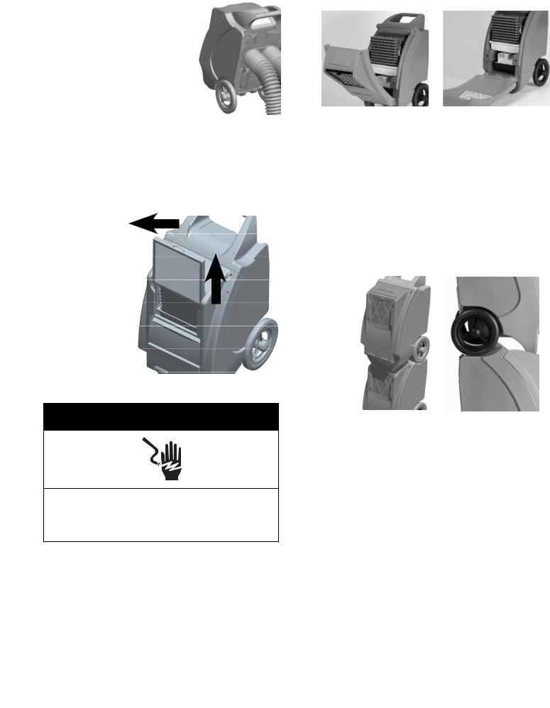
Venting / Ducting (Fig. 6)
Twin rear outlets can accommodate two individual 5” ducts or one 10” lay flat duct to be attached. This allows for warm dry air to be directed into different areas.
Fig. 66
MAINTENANCE
Air Filter (Fig. 7)
The air filter should be checked regularly. Operating the dehumidifier with a clogged filter will reduce efficiency. To access the filter, slide the filter frame up until it clears the dehumidifier cabinet. Reverse procedure to re-install the filter into the
Fig.
Industrial Dehumidifier
Fig. 8
Storage
Freezing temperatures and biological growth must be considered before storing the dehumidifier. The dehumidifier should be flushed with a biofungicide before storing. When storing the unit, ensure that water has been removed from the reservoir and hose. This will prevent damage caused by freezing temperatures and to prevent biological growth. Use the pump purge button to remove water and biofungicide chemicals from the dehumidifier.
Stacking (Fig. 9)
The dehumidifiers can be stacked on top of each other. The wheels from the upper unit must be resting in the cradle of the lower unit. DO NOT STACK MORE THAN TWO HIGH.
Fig. 9
MAINTENANCE
 WARNING
Electrical Shock Hazard Disconnect power supply before cleaning.
Failure to follow these instructions can result in death, fire, or electrical shock.
External Cleaning
Use a non-flammable mild, non-abrasive soap and clean water solution to clean the dehumidifier. Wipe dry.
Internal Cleaning
Disconnect dehumidifier from power supply.
Light cleaning: Remove the air filter and spray evaporator coil with water. Remove the two upper screws from the fronthood.
Heavy cleaning: Remove two upper screws from front hood. Open hood. Spray water at coils. Close hood and replace screws. (Fig. 8)
Service
A qualified refrigeration technician must service all refrigerant leaks.
WARNING: The dehumidifier uses a high pressure refrigerant system and high voltage circuitry which could present a health hazard resulting in death, serious bodily injury, and/or property damage. Only qualified service people should service this unit.
CAUTION: Do not operate unit without the front hood secured in place.
The serial data plate is located on the underside of the dehumidifier. For service information contact 1-800-565-3548.
3
TROUBLESHOOTING
The Unit is NOT working:
•Why do you believe the dehumidifier is not working?
•Is the power ON?
•Has the breaker tripped? – Reset breaker
•If in a wet area, is the unit plugged into a GFI protected circuit? – Excessive moisture will trip GFI. Remove from area.
•Is the unit being run off a generator? - Check output does not fluctuate as the unit will not operate at low voltage.
•If using an extension cord - Is the cord of the correct gauge for the distance run? (14 AWG up to 25’ and 12 AWG over 25’). Note: Verify voltage while unit is starting. Start up will cause the highest current draw and largest voltage drop. Even if plugged directly to outlet there can be a significant voltage drop. Never assume the voltage is ok without verifying.
•Is the unit draining? – Check the condensate receptacle. If full, the float is up and the unit will not operate – drain receptacle.
•Overpressure switch tripped. Check for fan failure or high ambient temperature. Display panel indicates defrost.
The unit continually ices up: Note that some ice buildup on the evaporator coils is normal but airflow should not be blocked.
•Is the fan working? – Fan not working, check run capacitor and fan unit.
•Is warm air blowing out the front of the unit? - No warm air, temperature may be too low. Raise temperature with supplementary source.
•Is the air filter clean and airflow unobstructed? – Clean filter. Unit should have a minimum of 10” clearance all around it.
•Dirty evaporator coils? – Clean coils.
•Defrost thermostat loose or not working? – Secure or replace.
•Defrost timer set incorrectly or defective? – Reset or replace.
•Temperature in the operating space is too low? - Raise temperature with supplementary source.
Unit moves some water but not as much as expected:
•Air temperature and Relative Humidity have dropped - Check levels with calibrated humidity meter and/or thermostat.
•Unit is in defrost cycle – Unit will start after cycle.
•Air filter dirty or airflow obstructed - Unit should have a minimum of 10” clearance all around it. Clean air filter and ensure adequate airflow/space around unit.
•Evaporator coils dirty – Clean coils.
•Restrictive or kinked exhaust ducting (if used) – Straighten out ducting.
•Defrost timer set incorrectly for conditions – Reset timer.
•Defrost thermostat defective - Replace
•Refrigerant charge is low – Have unit checked by qualified technician
•Defective compressor – Replace compressor by qualified technician as it requires recycling of refrigerant.
Unit runs continuously for days:
•Unit is working removing water - High Relative Humidity in space.
•Humidity or water is getting into the space – Find source and stop it.
•Unit is undersized for space – Use larger unit or multiple units.
•Poor air movement in space – Use air movers to increase movement.
Unit runs but does not pump water:
•Drain hose kinked or blocked – Straighten or unblock hose.
•Pump float stuck closed – Reset or replace.
•Pump not working – Check electrical operation with outside supply.
•Hose disconnected internally – Reconnect hose.
•Compressor capacitor bad – Check capacitor.
Fan runs but Compressor does not:
•Condensate pump not working – Check pump and float.
•Bad connection in pump circuit – Check connections.
•Bad compressor capacitor – Check capacitor.
•Defective control board – Replace.
•Defective compressor – Replace compressor by qualified technician.
•Defective time delay or Thermistor – Check and/or replace.
•Defective pressure switch – Check and replace.
Fan does not run. Compressor runs briefly but cycles on/off:
•Defective fan capacitor – Check capacitor.
•Loose connection in fan circuit – Check connections.
•Fan obstructed and not turning – Remove obstruction.
•Defective fan – Replace fan.
•Defective control board – Replace control board.
4

WIRING DIAGRAMS
EPD150LR, EPD180CR
EPD190LR, EPD250CR
5
 Loading...