

Page 1
Installation Manual
A.A.R. Combination
Railroad Track / MTS
Scale
Model(s): 12-1492
12-1493
12-1494
12-1495
12-1496
50538
Revision 7 4/12
© 1999-2012 by Fairbanks Scales Inc.
All rights reserved
Page 2

Page 3

04/12 3 50538 Rev. 7
Amendment Record
A. A.R. Railroad
Combination MTS Scale
Model(s): 12-1492,12-1493,12-1494,12-1495
50538
Manufactured by Fairbanks Scales Inc.
821 Locust
Kansas City, Missouri 64106
Created 9/99
Issue #1 9/99 Software Update.
Issue #2 12/01 Update arrangement/flow.
Issue #3 10/03 Updated Information and Drawings
Revision 4 05/08 Updated Load Cell Assembly image and corresponding parts information;
Added special Load Cell Appendix with parts list
Revision 5 05/08 Updated information and drawings according to notes from Engineering Dept.
Revision 6 03/10 Updates per ECO 626.
Revision 7 04/12 Updated information and drawings according to notes from Engineering Dept.
Page 4

Page 5

Table of Contents
Section 1: General Information
1-A: Introduction & General Description Page 9
1-B: Specifications Page 9
1-C: Rails & Anti-Creep Devices Page 10
1-D: Regulations from the AAR Scale Handbook Page 11
1-E: Foundation Construction & Installation Page 13
1-F: Ground Rods Page 14
1-G: Load Cell Base Plates Page 14
1-H: Check Stands Page 15
1-I: Weighbridge Page 15
1-J: Deck Construction Page 15
1-K: Load Cell Flexure Assembly Page 16
Section 2: Installation
2-A: General Service Policy Page 17
2-B: Pre-Installation checkout Page 17
2-C: Unpacking Page 18
2-D: Safety Page 18
2-E: Recommended Installation Sequence Page 19
2-F: Foundation Inspection Page 20
2-G: Foundation Inspection Check List Page 21
2-H: Base Plate Assemblies Page 22
2-I: Check Stands Page 22
2-J: Weighbridge Steel Page 23
2-K: Weighbridge Hardware Page 24
2-L: Assembling Weighbridge Sections Page 25
2-M: Installing Weighbridge Sections Page 27
2-N: Load Cell Flexure Assembly Page 29
2-O: Adjusting Elevation Page 31
2-P: Leveling Load Cell Flexure Assemblies Page 33
2-Q: Grouting Load Cell Baseplates Page 36
2-R: Checkrods Page 39
2-S: Check Rod Adjustment Page 41
2-T: Deck Forming Page 42
2-U: Junction Boxes Page 47
2-V: Grounding Page 47
Section 3: Service & Maintenance
3-A: Basic Maintenance Page 49
Section 4: Parts list
Parts List Page 50
04/12 5 50538 Rev. 7
Page 6

Table of Contents, Continued
Appendix I: Recommended Tools & Equipment Page 54
Appendix II: Required at Jobsite Page 55
Appendix III: Materials Page 55
Appendix IV: Torque Values Chart Page 56
Appendix V: Tolerances Page 56
Appendix VI: Load Cell Specifications Page 56
Appendix VII: Concrete & Sump Testing Page 57
Appendix VIII: About the AAR, AREMA, & AREA Page 58
Appendix X: Special Product Applications --
Short Load Cell Assembly Page 59
04/12 6 50538 Rev. 7
Page 7

Index of Illustrations:
50538-1 Deck with recessed rail Page 9
50538-2 Anti-Creep Device Page 10
50538-3 Rail Miter Cut Gaps Page 10
50538-4 Ground Rod Locations Page 14, 47
50538-5 Load Cell Flexure Assembly Page 16
50538-3A Foundation Inspection Check list Page 21
50538-6 Base Plate Installation Page 22
50538-7 Weighbridge Steel: Assembled Section Page 23
50538-7A Weighbridge Steel: Component Identification Page 23
50538-7B Weighbridge Hardware Page 24
50538-8 Weighbridge Steel Layout Page 25
50538-9 Weighbridge Steel Assembling Page 25
50538-10 Installing Weighbridge Checkbracket Page 25
50538-11 Installing Stiffener Plate & Top Bearing Plate Assy Page 26
50538-12 Centering Weighbridge Sections Page 27
50538-13 Centering Main Beams Page 28
50538-14A Load Cell Flexure Assembly; Exploded View Page 29
50538-15 Load Cell Flexure Assembly Orientation Page 30
50538-16 Load Cell Flexure Assembly; Centering Page 30
50538-17 Leveling End Section Page 32
50538-18 Leveling Middle Sections Page 32
50538-19A Load Cell Flexure Assembly; Leveling Page 33
50538-20 Load Cell Locations Page 34
50538-21 Base Plate Forming & Grouting Page 37
50538-22 Base Plate Forming & Grouting Page 38
50538-23 Base Plate Forming & Grouting: Sloping Grout Page 38
50538-24 Weighbridge Check Stands Page 39
50538-25A Check Rod Washer Sets Page 39
50538-26 Pier Check Stands Page 40
50538-27 Check Stands: Leveling Page 40
50538-28 Check Rods: Adjusting Page 41
50538-29 Deck with recessed rail Pocket Page 42
50538-30 Deck Forming: Hex Nut Spacers Page 42
50538-31 Deck Forming: Placing and Welding Deck Coping Page 43
50538-32 Deck Forming: Placing and Welding Deck Coping Page 43
50538-33 Deck Forming: 12 Corner Junctures Page 44
50538-34 Deck Forming: Deck Coping at Rails Page 44
50538-35 Deck Forming: Installing Corrugation Page 44
50538-36 Deck Forming: Installing Corrugation Page 45
50538-37 Deck Forming: Installing Rebar Page 45
50538-38 Deck Forming: Installing Bituminous Mastic Page 46
50538-39 Deck Forming: Steel Plates at End of Rail Pockets Page 46
50538-40 Junction Boxes Page 47
50538-41 Grounding Page 47
50538-42 Parts List Page 50
50538-14 Previous Load Cell Revision -- Before 1992 Page 59
04/12 7 50538 Rev. 7
Page 8

Page 9
04/12 9 50538 Rev. 7
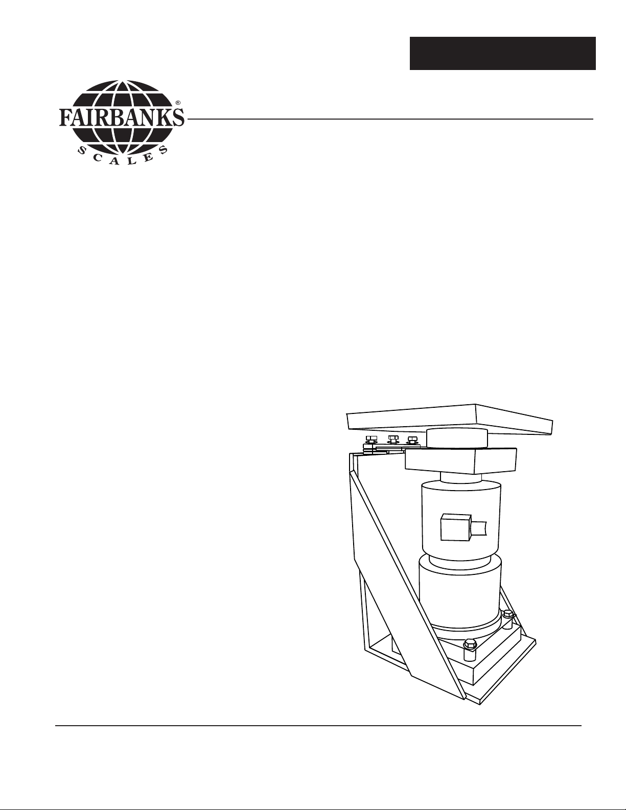
A.A.R. Combination Railroad Track / MTS Scale
NOTE: This manual is intended to compliment and be used in conjunction with the Certified
Prints provided by FAIRBANKS SCALES. Installation should be attempted only with the presence and guidance of experienced personnel who are fully familiar with the assembly of these
scales. Please read this Bulletin in its entirety BEFORE setting scale hardware.
SECTION 1-A: Introduction & General Description:
The Fairbanks Model A.A.R.* Combination Railroad Track / Motor Truck Scale is fully electronic in design, and utilizes eight 200,000 lb capacity compression loadcells that are constructed of Stainless Steel and hermetically sealed for protection against moisture. The four
(4) section Scale is pit installed, and is offered in five (5) different standard Models that provide a sectional capacity of 180 Tons, and a total capacity of 360 Tons.
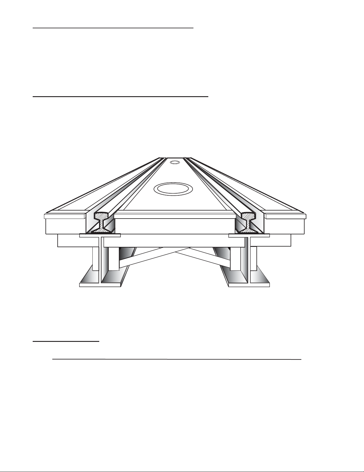
50538-1
The full platform of the scale is arranged to accommodate a railroad car or a motor truck for
weighing. The track rails are installed in a recessed rail pocket below grade, thus presenting
no obstruction to rubber tires. Interface to a Fairbanks 2500 Series Indicator with INTALOGIX technology is standard.
1-B: Specifications:
Product # Description Shipping Weight
145960 (90840**) Model 1492: 60' X 10' Platform 36,500 lb.
145966 (90841**) Model 1493 66' X 10' Platform 41,700 lb.
145970 (90842**) Model 1494 70' X 10' Platform 48,700 lb.
145972 (90843**) Model 1495 72' X 10' Platform 49,900 lb.
145980 (99179**) Model 1496 80’ X 10’ Platform 60,900 lb.
* The Association of American Railroads (AAR)
** These Item Numbers are now obsolete, replaced by the Item Numbers to the left.
Page 10
04/12 10 50538 Rev. 7
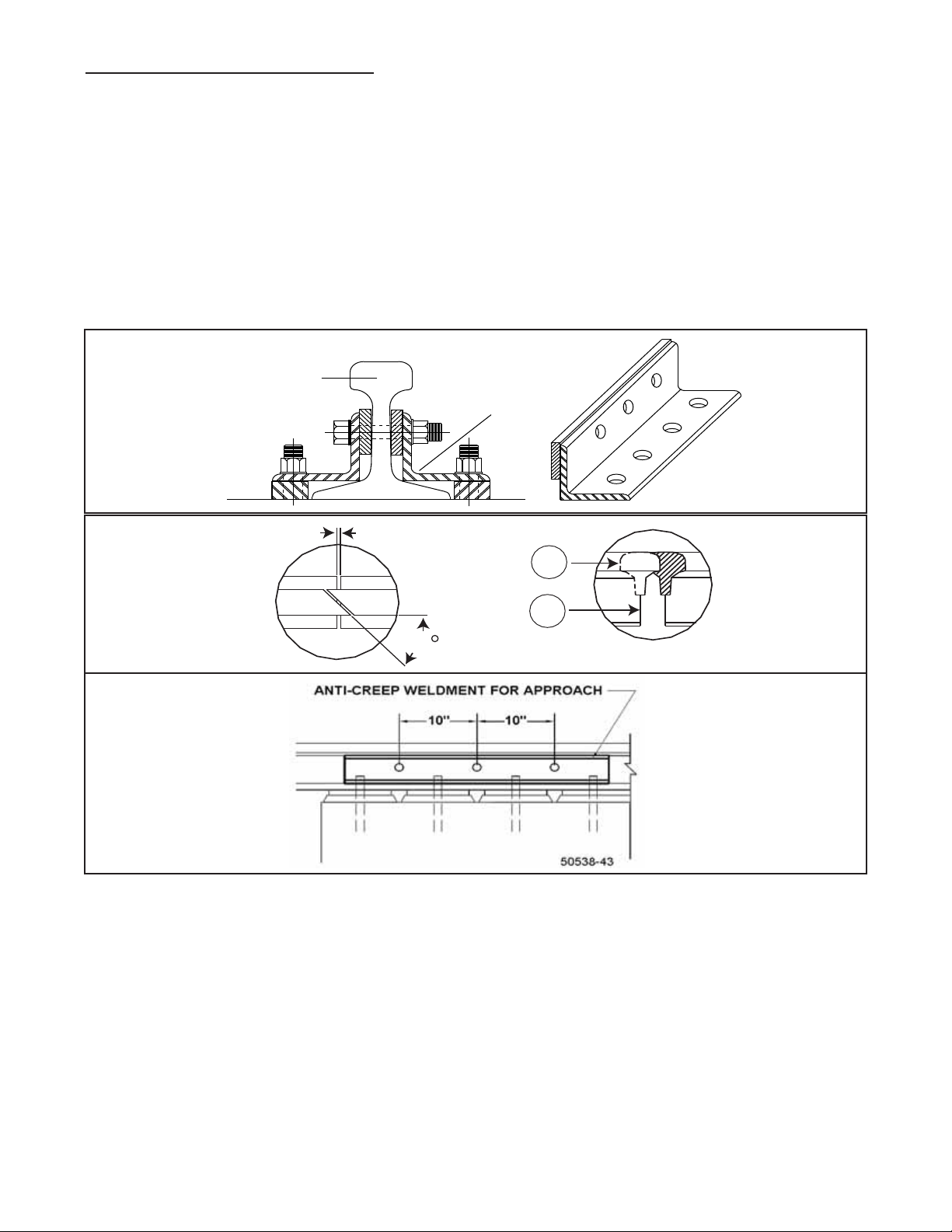
1-C: Rails & Anti-Creep Devices
The Scale is designed to accept a 115 lb. rail with Foster #62 rail clip. The approach rails
and Scale Weigh Rail should be the same weight. The approach anchor bolts, approach rail
plates, rail clips, and anti - creep devices are all optional items. They can be supplied by
Fairbanks Scales when ordered as accessories, otherwise they are not supplied.
Positive means must be provided by others to prevent the creeping of the approach rails and
to maintain a clearance which shall be not less than 1/8 inches or more than 5/8 inches
between the approach rails and the weigh rails. Switch points are highly recommended for
this purpose. A minimum of seventy five (75) feet of tangent track at each approach is
required by the A.A.R.
50538-2
Rail
Weldment
Anti-creep devices are constructed of angle iron with a flat iron weldment to fit to the rail as
shown above, The rail is side drilled through its web and bolted to the anti - creep device,
effectively securing it from any movement.
The AAR Scale Specifications state that the rail on the approach and the weighbridge shall be
properly anchored to prevent creeping of the rails. This is done in order to maintain the proper gap between the approach rail and the weighrail.
Rails should be miter cut at the ends of the weighrails and approach rails to assure a smooth
transfer of wheels in order to reduce impact loading to the scale.
NOTE: It is strongly recommended that any anti-creep device(s) be installed by qualified rail-
road maintenance and repair service personnel.
45
3/8 inch gap
1
2
50538-3
Page 11

04/12 11 50538 Rev. 7
1-D: Regulations:
This Scale is designed and manufactured in accordance with regulations established by
Handbook 44 as adopted by the National Conference of Weights and Measures (NCWM), the
Association of American Railroads (AAR), and the National Institute of Standards and
Technology (NIST). If the Scale is intended to provide weights to the serving railroad for the
purpose of revenue, it shall be installed, repaired, tested, and maintained in accordance with
the Association of American Railroads Scale Handbook, which contains the rules and specifications for the construction and maintenance of track scales for the weighing of railroad vehicles.
Excerpts from the Association of American Railroads Scale Handbook
Location: Scale shall be so located that an adequate foundation and at least 75 feet of
tangent track at each approach to the weighrails can be provided.
Elevation:
In areas with poor drainage, the scale shall be raised to such an elevation that
drainage of the surface water shall be away from it. Means shall be provided to prevent
accumulation of water at the scale site. Solutions for saturated areas with poor drainage shall
be determined by a competent soils engineer.
Drainage:
The pit floor shall be pitched to a common point for drainage and shall be
smooth and free from pockets in which water may stand. If the pit floor is below substrate
water lever, the pit shall be drained from its lowest point into a sump adequately equipped
with automatic means for removal of water as it collects.
Footing or Piers for loadcells:
Concrete footings or piers supporting load cell base plates
shall not be less than 18 inches thick. Their tops shall be above the floor a sufficient distance
to prevent the accumulation of water around or under the base plates.
Pit floor: The floor of the pit may be a mat of concrete approximately as thick as that
required to support the load cell base plates or, if local conditions permit, the thickness may
be reduced to no less than 6 inches.
Ventilation:
All scale pits shall be ventilated to meet the needs of each particular case to
minimize the relative humidity in the pit and to retard corrosion of scale parts and structural
steel.
Entrance to the Scale Pit:
Suitable access to the Scale pit shall be provided. The entrance
shall be closed by a suitable closure fastened to prevent the entry of unauthorized persons.
AAR Scale Handbook
Safety Piers:
Suitable piers, columns, or other supports should be provided to prevent
excessive drop of the girders if there should be a failure of other Scale parts. Clearance
should be maintained at full scale capacity.
Page 12

04/12 12 50538 Rev. 7
Bearing Pressures Under Foundations: The bearing areas of the foundation footings
shall be such that the pressure under the footings will not exceed:
For fine sand and clay .................................. 4,000 lb. per square foot
For coarse sand or hard clay ....................... 6,000 LB per square foot
For boulders or solid rock ........................... 20,000 LB per square foot
If the soil does not have a bearing capacity of at least 4,000 pounds per square foot, and its
bearing capacity cannot be increased by drainage, stabilization, or other means, pile foundations shall be provided. Careful soil exploration, including borings, is always desirable.
Leveling:
Load cell assemblies shall be raised or lowered, as required, by means of leveling screws, shims, or other methods to bring the weighbridge into level traversely and on
grade longitudinally. After leveling the load cell baseplates, to a tolerance of not more than
1/64” per foot, they shall be grouted as required.
Scale House Design:
Except where the indicating elements are mounted in a separate
building, a Scale house large enough to install, observe and service the indicating elements
shall be provided. It should have windows of sufficient size and so located as to give the
weigher an unobstructed view of the Scale deck and approaching cars or trucks.
Where a special scale house is required, a suitable and substantial building shall be provided. To insure proper operation of the indicator and/or recorder, the house shall be equipped
with proper environmental control.
Scale House Location:
The lateral clearance between the Scale house and centerline of
Scale or any track shall not be less than 8 feet, unless otherwise required by law, or the serving railroad.
Indicator - Recorder Shelf: If a shelf is required for mounting the indicator and/or recorder, it
shall be so located as to provide for ease of operation without obscuring the weigher's view
of the Scale deck and approaching cars or trucks. The shelf must not limit ready access to
the instrument for maintenance purposes.
Power Source
The power source of the electronic instrumentation and load cell circuitry
shall conform to the following:
Voltage - 115 v AC +/- 10 v
Frequency - 60 Hz, +/- 0.25 Hz
The power source must be reasonably free from harmonics and electrical transients.
Fusing shall be provided at 15 amp unless otherwise specified by the manufacturer.
The power source shall be a separate circuit back to the distribution transformer.
One side of the 115 v power source shall be at a ground potential.
Power surge protection shall be provided for load cells and instrumentation circuit.
Adequate protection of shielding should be provided to eliminate radio frequency and electromagnetic interference. The scale must satisfy the tolerance requirements when the scale
equipment is subjected to RFI and EMI influences.
Page 13

04/12 13 50538 Rev. 7
Cabling:
All cabling between loadcells, junction boxes, and electronic instrumentation shall conform to
the following:
All cable shields shall be interconnected and carried to a single ground. This should be a separate ground from the power source ground and be provided for the loadcells and instrumentation circuits only. It should be a copper rod which, when possible, is driven to the depth of
the water table.
The connection between the ground rod and the common ground point of the load cell and
instrumentation circuits shall be made with copper wire, or the equivelant, of No. 10 gauge or
larger.
All cable shields in the load cell circuits shall be grounded at one end only.
Homerun cables shall be physically separate from power cables and never run in the same
conduit system.
(NOTE: A 24 inch to 36 inch separation is required by Fairbanks Scales)
All cable connections, junction boxes, etc., in the load cell circuits shall be properly protected
against the effects of moisture.
All multi - conductor cabling shall be color - coded, or provided with other means of identification of the individual conductors.
1-E: Foundation Construction & Installation
Use only certified prints that are marked for the particular installation, customer, and scale.
All the dimensions indicated on the certified prints must be rigidly and faithfully followed during all phases of construction. There is very little tolerance for misplacements and mistakes.
Pier heights are especially critical as there must be enough space for finishing grout under all
stands (per certified drawings) while rails on the scale weighbridge and approach rail must be
absolutely level.
Placement of foundation bolts is absolutely critical to the successful installation of the scale.
The use of a template or form that matches the design called for can be used. Foundation
bolts must NOT be installed at an angle, too deep, or too shallow. Very close tolerances must
be met on all aspects of pit construction.
Page 14
04/12 14 50538 Rev. 7
1-F: Ground Rods:
Ground rods are essential in providing protection to the electronic components and loadcells
from both lightning surges and static discharges. Pit ground rods shall be tied to the foundations steel reinforcement rod (rebar) prior to pouring, and shall protrude 4 inches above the
pit floor.
Ground rods for approach rails shall be installed in the approach rail cut-outs and tied to the
rebar assembly. Fairbanks provides the three ground rods located in the pit as part of the
standard foundation kit. The two ground rods in the approach must be provided by others.
There are five (5) rods with the locations specified as below:
One (1) ground rod at each end, in the approach rail-cuts, for approach rail grounding. *
One (1) ground rod at each end, in the pit, for steel weighbridge grounding. *
One (1) ground rod at the pit load cell conduit location for the pit power supply. *
The following drawing shows correct placement of ground rods.
1-G: Load cell Base Plates:
The Load cell base plates are the foundation upon which the scale structure rests, and their
level, accurate position is basic to the entire structure. Base plates must be installed at proper
height and in the same plane. All base plates must be level within 1/64” per foot. All pier bolts
must have enough height to allow vertical adjustment of the base plate's, but not so high as
to interfere or to have insufficient depth into the pier.
* Fairbanks provides the three (3) ground rods located in the pit as part of the standard
foundation kit. The two (2) ground rods in the approach must be provided by others.
Top View of Scale
#2
#4
#5
#3
#1
= Ground Rod
In Pit Floor
In Pit FloorIn Pit Floor
Conduit
In approach rail cutout
Supplied by others
In approach rail cutout
Supplied by others
#4 & #5 Ground Rods Not supplied or Installed by FAIRBANKS
50538-4
Page 15

04/12 15 50538 Rev. 7
1-H: Check Stands:
Check rods allow for vertical movement in order to transfer weight force to the load cells but
they do not allow for lateral or side movement. Checking stands must be level and on the
same plane. All check rods must be level within 1/100” per foot when weighbridge is at correct elevation. Grouting the check stands MUST NOT take place until the load cell base
plates are adjusted to their final height.
1-I: Weighbridge:
The weighbridge supports the loads applied to it, and transfers that weight to the load cells.
Properly installed, this transfer allows the load to be shared by all cells and keeps loading in a
vertical direction. For both safety and expediency, it is recommended to assemble the weighbridge steel in sections outside of the pit, then setting the assembled sections into the pit one
at a time with a suitable capacity crane.
The weighbridge must be square and the main girders must be vertically plumb so that the
bottoms of the main girders are level. Do NOT weld the "X" bracing at the ends of the weighbridge or use impact wrench on steel structure bolts until girders are in place and are plumb.
Main beams must be joined at sections so that the top flanges are level to accommodate the
track rails with full contact support without shimming. Due to steel manufacturing tolerances,
the height of the main beams may be slightly unequal making the bottom flanges uneven. If
shims are required, place between the stiffener plate and the main girder. Full contact shimming is required for stiffener plates. Shims are not supplied with the scale hardware. The
resulting upper stiffener plate and top bearing plate must be level within 1/64” per foot.
1-J: Deck Construction:
The construction of the deck will cover the areas alongside and in-between the main beams
and Rails, and will provide a custom fitted concrete deck for motor truck and vehicle weighing.
All concrete workmanship shall be performed in accordance with the best practice as
described by the American Concrete Institute. The recommended slump is four to six inches
(4" to 6").
Allow concrete to cure thoroughly. Do not use, or subject the deck to any traffic until the concrete has attained its ultimate compressive strength of 3000 psi after 28 days.
The steel supplied for the deck construction is precut at the factory to fit an exact dimension
pit, as indicated on the prints.
Page 16
04/12 16 50538 Rev. 7
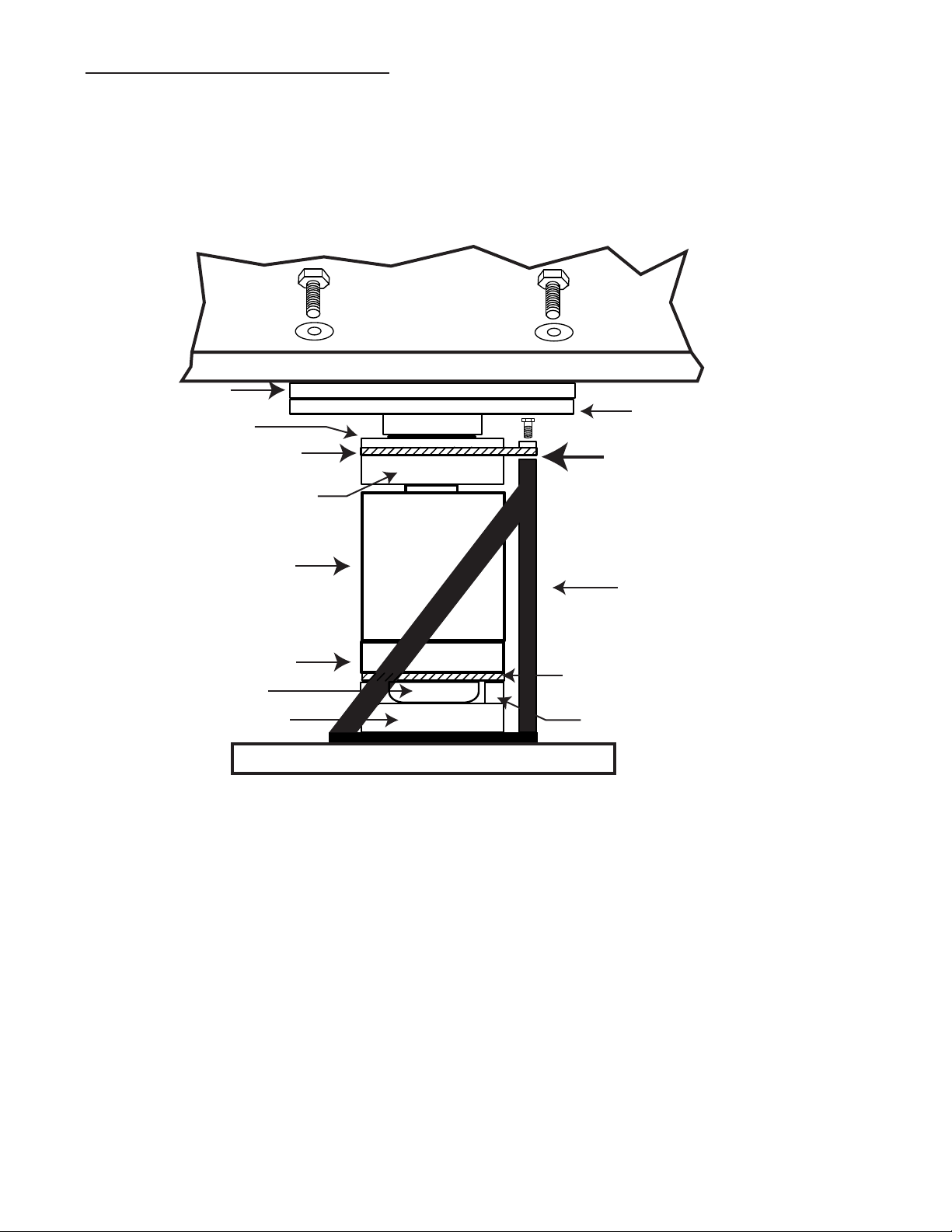
1-K: Load Cell Flexure Assembly:
The Load cell flexure assemblies maintain the load cells in a vertical position. In application,
the design uses a 200,000 lb capacity compression load cell mounted in a support assembly.
The support assembly contains an upper flexure assembly protected by a wear plate, and
weight(s) applied to the scale are transferred to them from the top bearing plate assembly.
Support Assembly
Shims (as required)
Main Girder
Stiffener Plate
Top Bearing Plate Assy
Wear Plate
Lower Bearing Plate
Spacer (4)
Lower Button
Lower Flexure
Load Cell Spacer
Load Cell
Upper Button Bearing Assy
Upper Flexure Assy
Base Plate
50538-5
The flexure assembly isolates any lateral movement of the main girder from the top of the
load cell. This arrangement allows the cell to remain vertical under all loading conditions, and
to minimize the side-load effects of thermal expansion and contraction of the weighbridge.
Page 17

04/12 17 50538 Rev. 7
Section 2: Installation:
2-A: General Service Policy
Prior to installation, it must be verified that the equipment will satisfy the customer's requirements as supplied, and as described in this manual. If the equipment cannot satisfy the application and the application cannot be modified to meet the design parameters of the equipment, the installation should not be attempted.
Overview:
1. These instructions apply to the Scale Platform only; installation procedures for instrumenta-
tion, printers and other peripherals are given in manuals specifically provided for those units.
The instructions include a pre-installation checkout, which must be performed before the
installation.
2. All electronic and mechanical calibrations and or adjustments required to make this equipment perform to accuracy and operational specifications are considered to be part of the
installation, and are included in the installation charge. Only those charges which are incurred
as a result of the equipment's inability to be adjusted or calibrated to performance specifications may be charged to warranty.
3. Absolutely no physical or electrical modifications are to be made to this equipment.
Electrical connections other than those specified may not be performed, and no physical
alterations (mounting holes, etc.) are allowed.
4. The installing technician is responsible to make certain that personnel are fully trained and
familiar with the capabilities and limitations of the equipment before the installation is considered complete.
2-B: Pre-Installation Checklist:
The following points should be checked and discussed with the Area Sales Manager and/or
customer, if necessary, before the technician goes to the site to install the equipment.
1. Has the customer's application been checked to make certain that it is within the capabilities and design parameters of the equipment?
2. If the installation will disrupt the customer's normal operations, is he aware and has he
made arrangements?
3. Is properly-grounded power available at the installation location?
4. Will the equipment operator(s) be available for training?
Page 18

04/12 18 50538 Rev. 7
5. Has the service technician thoroughly reviewed the installation procedures?
6. Has the service technician reviewed the recommended setup with the Area Sales Manager
or Area Service Manager, and identified all necessary variations to satisfy the customer's particular application?
2-C: Unpacking:
1. Check that all components and accessories are on hand, and agree with the customer's
order.
2. Remove all components from their packing material, checking to make certain that all parts
are accounted for and no parts are damaged. Advise the shipper immediately, if damage has
occurred. Order any parts necessary to replace those which have been damaged. Keep the
shipping container and packing material for future use. Check the packing list.
3. Collect all necessary installation manuals and prints, including Certified Prints, for the
Scale being installed.
2-D: Safety:
As is the case with any material handling equipment, certain safety precautions should be
observed during operation:
1. Never load the platform beyond its rated capacity. Refer to the rating on the serial number
plate if in doubt.
2. Ensure that any structure which supports the platform is capable of withstanding the weight
of the platform plus its rated capacity load.
3. Do not load the platform if there is any evidence of damage to the platform or supporting
structure.
4. Use safety chains or other suitable restraining devices if there is any possibility of the load
shifting, falling, or rolling from its position on the load receiver.
5. Do not leave the platform unattended when it is loaded.
Page 19

04/12 19 50538 Rev. 7
2-E: Recommended Installation Sequence:
After pit is completed, follow this sequence:
Measure pit squareness, depth, width, and length against certified prints
Measure cast-in anchors, pier elevation on all piers against certified prints
Dimensions MUST be correct before installing scale hardware
Using packing list, be sure all scale elements/parts have arrived intact and Undamaged
Then install:
Base Plate Assemblies
Check Stands
Wood blocking and cribbing
Weighbridge Steel
Weighbridge Sections
Load Cell Flexure Assembly
Adjusting Elevation
Leveling Load Cell Flexure Assemblies
Grouting Load Cell Baseplates
Checkrods
Grouting Check Stands
Check Rod Adjustment
Deck coping, manholes, deck forming, deck rebar
Grounding
Rail and anti-creep devices
Form and pour concrete deck
When deck is cured, install:
Complete wiring of load cells
Instrumentation and any peripheral equipment
Calibration and testing
Page 20

04/12 20 50538 Rev. 7
2-F: Foundation Inspection
Excerpts from Fairbanks Scales form FF-2267; Foundation Field Check list
A Foundation Inspection should ALWAYS be performed prior to Scale installation, to confirm
the Foundation is constructed correctly and is ready for installation. If possible, this should
be done prior to the scale shipment.
TOOLS REQUIRED:
Certified drawings and site plan. 2' to 4' level
25' & 100' steel tape measures Hammer and concrete nails
Hacksaw laser or builders level if possible
String line (construction string) straight edge for pit foundations
Construction Spray Paint (upside down type, for marking concrete)
Perform the following Foundation checks. It is recommended to keep a copy of the check list
with the job file. ALWAYS familiarize yourself with the CERTIFIED FOUNDATION PRINTS for
the job you are working on as model numbers and their specifications are subject to change.
1: Site Plan and Certified Prints should be thoroughly reviewed to confirm accurate locations
to the scale and all extra items ( scoreboards, lights, poles, etc.) that are included.
2: Check for truck and crane access, overhead wires, fences, green concrete, etc. .
3: Dimensional length and width check; check all 4 sides and record on chart.
4: Diagonal measurements check to verify that the Foundation is square and record on chart.
These measurements should be equal, or within ½ inch. Greater error could result in the
scale not fitting in the Foundation.
5: Check ALL pier heights to make sure they are at the correct elevation and record on chart.
6: Check the pit walls to verify they are straight.
7: Verify Ground Rod locations.
8: Verify conduit locations and pull strings.
9: Verify that drains and sump openings are piped correctly are clear of debris.
10: Check the end coping to ensure they are centerline and that the coping is correct for the
scale being installed (10', 11', 12', width, etc.). Check all coping, side and end, for hollow
areas.
11: Verify location(s) of any and all required embeds
Record all measurements and observations. Physically mark any discrepancies with the
marking paint. Do not proceed with Installation until corrections have been made.
Page 21

04/12 21 50538 Rev. 7
2-G: Foundation Inspection Check list
Length & Width Check
Diagonal Measurements
Check
A
B
Pier Height Check
Pier
Pier
Side View
Strings
1
2
3
4
5
6
7
8
9
10
1:
2:
3:
4:
Measurement A to A=________
Measurement B to B=________B
A
B
A
B
A
A = Coping length
B = 1/2 of the coping length, or Centerline
C = Distance from Centerline to load cell Center lines
C
L
Loadcell Center Line
Loadcell Center Line
C
C
C
C
C
L
= Concrete Nails
= Centerline of Scale
50538-3A
Page 22

04/12 22 50538 Rev. 7
2-H: Base plate assemblies:
Caution: Base plates weigh approximately 245 lb.each. Work Safely.
1: Clean the top of the piers thoroughly, and ensure they are free of any oil or grease
deposits. Clean the threads of all base plate pier bolts with a wire brush, using a thread file
to restore any damaged threads. Lightly grease the threads, and ensure the threads are
clean and in good condition by running a threaded nut down and up the full threads of the
bolt. Remove all nuts from the pier bolts.
2: Place several short lengths of wooden 2 X 4's or 4 X 4's in the center of the pier bolts,
and place the base plate onto the wooden blocking on the pier, guiding the 4 pier bolts into
the 4 corner holes of the baseplate.
Base Plate
Pier bolts
Leveling
Screws
1/4" Flat steel
Concrete Pier
50538-6
3: Insert greased leveling screws into the provided tapped holes in the base plates, and
place a cut piece of 1/4" Flat Steel under each leveling screw. Adjust each screw to raise the
base plate off of the blocking and to approximately level the base plate. Remove the blocking
from underneath the base plate. Place flat washers and nuts on the pier bolts loosely.
2-I: Check Stands:
1: Clean the top of the piers thoroughly, and ensure they are free of any oil or grease
deposits. Clean the threads of all check stand pier bolts with a wire brush, using a thread
file to restore any damaged threads. Lightly grease the threads, and ensure the threads are
clean and in good condition by running a threaded nut down and up the full threads of the
bolt. Remove all nuts from the pier bolts.
2: Place several short lengths of wooden 2 X 4's in the center of the pier bolts, and place the
check stand onto the wooden blocking on the pier, guiding the pier bolts into the holes of the
check stand.
3: Insert greased leveling screws into the provided tapped holes in the check stands, and
place a cut piece of 1/4" Flat Steel under each leveling screw. Adjust each 5/8-11 X 4" screw
to raise the base plate off of the blocking and to approximately level the check stand.
Remove the blocking from underneath the check stand. Place flat washers and nuts on the
pier bolts loosely.
Page 23

04/12 23 50538 Rev. 7
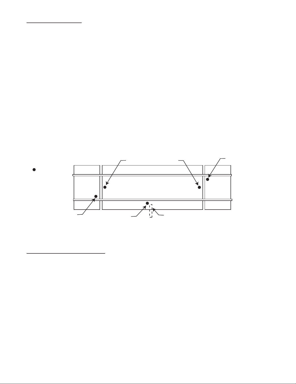
2-J: Weighbridge Steel:
Caution: Individual Steel beams can weigh as much as 5,500 lb. each. Work Safely.
Assembling in Sections:
It is recommended to assemble the weighbridge in 3 sections near the pit, with each section
located near its intended installation location. The means to safely move and position the
various steel beams will be required to facilitate the assembling of the weighbridge.
50538-7
Main Beam
Crossmember
Outrigger
Diagonal Cross Bracing
A suitable capacity hydraulic crane, and personnel familiar with safe and effective rigging
methods using flexible non-metalic rigging of suitable capacity is recommended to handle and
position the beams.
The Diagonal Cross Bracing is not installed until the Weighbridge is in the pit, and has been
made plumb, is squared up and has been leveled.
Loadcell Top
Bearing Plate
Weighbridge
Check Bracket
Stiffener
Connecting
Web Splice
Plates
Plates
Upper
Crossmember
Lower
Crossmember
Plate
50538-7A
Page 24

04/12 24 50538 Rev. 7
2-K: Weighbridge Hardware
1
5
2
3
4
1
4
Loadcell Top
Bearing Plate
Weighbridge
Check Bracket
50538-7B
1: Part # 54532; 3/4-10 X 3" Hex Bolt. Qty 32 required to connect the load Cell Top Bearing
Plate Assy's to Main Beam bottom flange. Their final Torque value is 150 foot pounds.
Note: The Load Cell Top Bearing Plate Assy mounting holes are tapped 3/4-10.
2: Part # 54229; 3/4-10 X 3 1/2" Hex Bolt A325 with Nut. Qty 16 required to connect the
mid section connecting plates to the bottom of the Main Beams. These bolts are installed to
the connecting plates end, outside holes only. Their final Torque value is 250 foot pounds.
3: Part # 54199; 3/4-10 X 2 1/4" Hex Bolt with Nut. Qty 36 required to connect the lower
cross members to the Main Beams. Their final Torque value is 250 foot pounds.
4: Part # 54217; 3/4-10 X 3" Hex Bolt A325 with Nut. Total Qty 232 required. Their final
Torque value is 250 foot pounds.
Qty 168 required to connect Crossmembers and Outriggers to the Main Beams.
Qty 64 required to connect the Web Splice Plates to the Main Beams at the Mid Sections.
5: Part # 54402; 1" X 3 1/2" Hex Bolt A325 with Nut. Qty 32 required to connect the Check
Brackets to the bottom of the Main Beams. Their final Torque value is 640 foot pounds.
Not Pictured:
Part # Description Qty Used On:
54342 1 1/2-6 Hex Nut 64 Check Rods
58617 1 ½ Spherical Washer Set 32 Check Rods
55766 3/4" X 1 1/4" Bar, J Box 5 Junction Boxes
Page 25

04/12 25 50538 Rev. 7
2-L: Assembling Weighbridge Sections
1: Identify each main beam pair per the certified prints, and select the appropriate end sec-
tion beams as the first to begin assembling. Place one main beam onto blocking, ensuring it
is supported and stable. Place the second main beam onto blocking, in parallel with the first
main beam, and close enough together to enable the middle crossmembers to be placed into
position
Crossmembers
Outriggers
Orientation
50538-8
temporarily by laying them down onto the bottom flanges of the main beams and in-between
them. Note the correct orientation of these crossmembers as indicated by the certified prints.
Place the outriggers near their intended installation location, and the mounting hardware.
Main Beams
Crossmembers
Outriggers
Orientation
50538-9
2: Starting at one end of the section, install the first crossmember into position, along with
both outriggers, leaving the bolts loose. Install the next crossmember, with its outriggers, and
proceed in order to the other end of the section. A chain come-along (with suitable capacity)
at the opposite end of the main beams can be used to slowly draw the main I-beams together
as the crossmembers and outriggers are being installed. When all crossmembers and outriggers have been installed in this manner, tighten all bolts. Do not tighten to their final torque
value at this time.
3: Locate the Weighbridge Checking Bracket locations on the lower flanges of the main
beams, and per the Certified Prints. Raise that area higher and support it with blocking, the
bracket will require a minimum of fifteen (15) inches of clearance. Install and tighten the
weighbridge checking bracket.
50538-10
Page 26

04/12 26 50538 Rev. 7
4: Install the stiffener plate and the top bearing plate assemblies. The mounting bolts will
install into the Top Bearing Plates threaded holes. Do not tighten to their final torque value at
this time. Do not perform any welding to the end sections at this time.
Stiffener Plate
Top Bearing Plate Assy
Hex Bolts
Flat W ashers
Main beam
50538-11
5: In similar manner, assemble the center section (s), and the other end section.
Page 27

04/12 27 50538 Rev. 7
2-M: Installing Weighbridge Sections
Caution: Weighbridge Sections can weigh as much as 17,000 lb. each. Work Safely.
1: Place wooden blocking and cribbing material suitable for supporting and jacking the
weighbridge steel into position near each pier and base plate. Each section will require four
points of support, therefore arrange the placement of these supports accordingly. It is recommended to set blocking to support the weighbridge against the pit wall, and 1 to 2 inches
higher (than the certified prints indicate its final elevation should be) at this time. If Safety
Piers have been installed, they can be utilized in lieu of blocks provided they are thoroughly
and completely cured.
2: With a crane and rigging (4 leg drop) of suitable capacity, install an end section into the
pit, and onto the supports. Set up a mason line to check and ensure that the centers of the
main beams are centered on the rail cutouts in the concrete approaches for the entire section.
Plumb bob
Mason line
50538-12
3: Ensure the distance from the approach pit wall is correct to ensure equal clearance at
both ends.
Page 28

04/12 28 50538 Rev. 7
50538-13
ABOVE: Check weighbridge steel for squareness by suspending a plumb bob at the
juncture of the previously established "centering" line, and at the juncture of the middle web
of the main beams. Measure and observe the distance between the plumb bob line and the
web, it should be the same at the top and bottom.
4: When end section has been centered, install the middle section, and connect the sections
together as indicated on the certified drawings. The top flange of the joined main beams
must be level and on the same plane to fully support the track rail without shimming. When
this is completed, and all plates and bolts have been installed, tighten all bolts to their final
torque value.
5: Install the other end section in the same manner, checking to ensure that the centers of
the main beams are centered on the rail cutouts in the concrete approaches for the entire
scale.
Ensure the top flanges of the main beams are level, install all plates and bolts, and tighten all
bolts to their final torque value.
NOTE: Do not weld in the Cross Bracing until the bridge is leveled and the dead load is balanced. See Step 9 on page 35.
Page 29

04/12 29 50538 Rev. 7
2-N: Load Cell Flexure Assembly:
Page 30

04/12 30 50538 Rev. 7
End
Center
50538-15
Referring to the detail above, note that the "open" side of the assemblies at end sections face
the center of the scale; middle sections have assemblies installed with the "open" side facing
the end of the scale.
TIP: For Analog Instrumentation, measure the bridge resistance of each load cell, and pair
the closest matches for installation in each section.
Lower Assembly:
1: Ensure the base plate is clean and free from any dirt and debris. Place the support
assembly into position, correctly orienting it in the appropriate direction and approximately
centered on the base plate.
2: Apply grease and install the two 5/8-18 x 1¼” socket-set screws (headless) in the holes at
the bottom plate of the support assembly to serve as locating pins for the lower bearing plate.
3: Place the lower bearing plate in position with the two holes engaging the locating pins.
4: Place the lower button's threaded stud through the center hole of the bottom flexure. Apply
grease to the threads. Place the stainless steel spacer (4” diameter, 1/8” thick) over the stud
so that it rests on top of the flexure plate.
5: With the load cell supported on its side, place the lower button/flexure/spacer against the
base of the load cell with the center hole aligned. Then screw the lower button/flexure/spacer
into the cell until all threads are very snug. Turn the lower button with large pliers, being careful not to bend or damage the lower flexure in any way.
6: Position the four spacers at the corners of the lower bearing plate concentric with the
tapped ½" holes.
7: Carefully lift the load cell assembly upright, and place it into the support assembly with the
load cell wiring junction facing the open side of the support assembly.
8: Apply grease and install four ½"-13 x 1½" screws and lock washers through the lower flexure and pipe spacers, and turn them into the corner holes of the lower bearing plate.
Page 31

04/12 31 50538 Rev. 7
Upper Assembly:
1: Place the upper button bearing assembly to the underside of the upper flexure assembly.
With the wear plate correctly orientated as to its corner countersunk holes, apply grease and
install the four ¼-20 x ½” flat-head screws through the wear plate, flexure assembly, and into
the bearing assembly.
2: Position the flexure and bearing assembly on the top of the load cell with the three holes
at the edge of the flexure facing the three holes in the mounting block at the upper rear of the
support assembly.
3: Position the mounting block bar, and loosely install three ½-13 x 1-1/4” hex bolts and lock
washers to hold the flexure assembly and bar into position. Apply grease to the bolt threads.
2-O: Adjusting Elevation:
1: With all load cell support assemblies installed, assembled, and placed upon the load cell
base plates as described in the preceding pages, prepare to carefully lower the weighbridge
onto each load cell support assembly one at a time with a hydraulic jack of sufficient capacity.
Starting with an end section, lower the weighbridge onto the load cell support assemblies at
that section one at a time.
Support Assembly
Main Girder
Top Bearing Plate Assy
Base Plate
Wear Plate
C
Hex Bolts & Lock W ashers
50538-16A
Ensure that the top bearing plate centers on the wear plate at each flexure, moving the
entire assembled load cell support assembly on the base plate as required to accomplish this
centering. Ensure the hex bolts that connect the top flexure plate to the support assembly
stand are inserted but not completely tightened before lowering the weighbridge onto the load
cell support assembly. Continue until the weighbridge is completely supported by the loadcells.
DO NOT REMOVE THE SUPPORTING BLOCKING AND CRIBBING AT THIS TIME.
LEAVE THEM IN PLACE CLOSE TO THE MAIN BEAMS TO SERVE AS A SAFETY PIER.
Page 32

04/12 32 50538 Rev. 7
Main Beam
Level Approach
Main Beam
Pit coping
Deck coping
50538-17
2: For the end sections, the elevation reference is the end wall (approach) pit coping. Place
and clamp deck coping across the main beams at an end section facing the pit wall coping.
Adjust the load cell base plate leveling screws of both base plates in the end section to level
the approach as shown above. Ensure both base plates are also level to within 1/64” per
foot.
3: Proceed to the next section, which is a middle section. Ensure the hex bolts that connect
the top flexure plate to the support assembly stand are inserted but not completely tightened.
Ensure that the top bearing plate centers on the wear plate at each flexure, moving the entire
load cell support assembly on the base plate as required to accomplish this centering. Lower
the weighbridge onto the load cell support assemblies.
4: For the middle sections, the elevation reference is both the absolute level of the main
beams with respect to the end sections, and the equal loading of the loadcells that support
the middle of the scale. Adjust the load cell base plate leveling screws to level the main
beams. Alternately, a transit can be used to compare and maintain elevation, and a tightly
stretched mason line. Ensure both base plates are also level to within 1/64” per foot.
Main Beams
Maintain same elevation
LEVEL
LEVEL
50538-18
5: Repeat these steps for the remaining sections of the scale.
Page 33

04/12 33 50538 Rev. 7
2-P: Leveling Load Cell Flexure Assemblies:
ener Plate
Top Bearing Plate
Upper
Flexure
Base Plate
LEVEL
Main Beam
LEVEL
Upper
Flexure
Base Plate
Top Bearing Plate
LEVEL
LEVEL
Load
Cell
Load
Cell
A
B
50538-19A
1: Starting at one end section, lift the main beam slightly from one load cell at a time and
loosen the three screws that secure the flexure to the support assembly block, and note any
space between the flexure and the block. Use a precision level across the flexure and add or
remove shims between the flexure and the block to get best possible level on the flexure and
insure there are no spaces or gaps (see "A" above). Tighten the three screws to torque specifications.
2: Check that the top bearing plate assembly is level and at right angles to the main beam
web. If adjustment is necessary, install shims only between the main beam's lower flange
and the stiffener plate ( see "B" above). Shims must extend the full length of the bearing
surface.
3: Check that the load cell is vertical and that the top bearing plate is centered on the flexure
wear plate. Adjust if necessary. Ensure the base plates, load cell, upper flexure plate, and
top bearing plate assembly are level to within 1/64” per foot.
4: Continue for each load cell flexure assembly.
5: Providing a suitable power supply to connect to the loadcells, measure and record the
mV/V output from each load cell in the scale. The resulting readings will indicate the current
weight distribution of the scale's deadload among the eight (8) points of support. The outputs
will be greater for number's 3, 4, 5, and 6 because there is physically more deadload weight
upon them.
Page 34

04/12 34 50538 Rev. 7
Top View of Scale
Loadcell's
Conduit
1
2
3
4
5
6
7
8
50538-20
This final base plate elevation adjustment should be made to match the mV/V outputs of the
load cells to assure correct distribution of the scale's deadload among the eight (8) points of
support. Adjust the base plate leveling screws (equally) to match loadcells 3, 4, 5, and 6.
Then adjust to match loadcells 1, 2, 7, and 8. When this has been completed, ensure each
load cell base plate is level to within 1/64” per foot.
NOTE: The load cell numbering sequence shown is designed for interfacing Fairbanks INTALOGIX technology instrumentation.
6:
Perform a final check to all:
• Load cell base plates are level to within 1/64” per foot.
• All Cell assemblies are centered on base plates, & All Load cells are vertical and plumb
• Top bearing plate centers on the wear plate at each flexure
• Top bearing plate assembly and stiffener plates are level to 1/64” per foot and at right
angles to the main beam web(s).
• Upper flexures are level to 1/64” per foot with weight and without weight, and shimmed
properly
• Top flanges of the main beams are absolutely level and on the same plane as the end sections.
• There is correct distribution of the scale's deadload among the eight (8) points of support.
• All assembly hardware is secure
Page 35

04/12 35 50538 Rev. 7
7: Insulate and separate each load cell's wiring from adjoining wires and from the steel with
insulated electrical tape. Be certain load cell cables are isolated from contact with steel and
not attached to any junction boxes.
Be certain load cell cables are isolated from contact with steel and not attached to
junction boxes. Welding ground should be kept as close to the electrode (welding rod)
end as is practical.
DO NOT PERMIT ELECTRIC ARC CURRENT TO CONDUCT THROUGH A LOAD CELL(S)
8: Weld the support stands to the load cell base plates per certified drawings. Welding
ground must be on the same physical side of each load cell as the electrode (welding rod)
end.
9: Install and weld all section "X" bracing per the certified prints.
10: All structural steel shall have one shop prime coat. Areas around field welded connec-
tions shall be painted. Immediately following the connecting of the members, the heads, nuts,
and washers of all permanent bolts, all field welds after removal of residual flux, all abrasions
of the shop prime coat, and all field erection marks shall be thoroughly covered with one coat
of primer.
Page 36

04/12 36 50538 Rev. 7
2-Q: Grouting Load Cell Baseplates:
Grout becomes the base which supports the entire structure. Grout MUST be fully supporting
the stands and plates with NO gaps or spaces. A good method is to build the forms slightly
bigger than the stand to permit the pouring and the rising of the grout mixture.
The pier should be thoroughly saturated with clean water for a minimum of 4 hours. This will
both prevent the dry pier concrete from absorbing water from the mix as it is poured, and
greatly enhance the ability for the grout mix to bond with the pier.
1. Grout selection:
Grout shall be precision, packaged dry, non-metallic, hydraulic, non-shrink, and non-gaseous.
Grout shall meet or exceed ASTM C-1107 and Corps of Engineers CRD-C621.
Grout shall be bleed free and attain a minimum
of 8000 psi compressive strength in 28 days
at flowable consistency.
Grout MUST be mixed to a flowable consistency as specified by the grout manufacturer.
Do not permit any loads upon the scale until the grout has reached the compressive strength
of 8000 psi per the grout manufacturers instruction.
2. Surface preparation:
• Surfaces to be grouted shall be prepared in accordance with the manufacturers instructions.
• Surfaces to be grouted shall be free of loose debris, grease, oil and other contaminant’s.
• Contaminant’s shall be removed using caustic soda or other approved concrete cleaners.
• All surfaces shall be flushed with clean water.
• Prior to pouring, all surfaces should be saturated with clean water for a minimum of 4 hours.
Page 37

04/12 37 50538 Rev. 7
1.0" Min.
3"
Min.
Grout
3"
Min.
Concrete Pier
Forms
(Typ.)
Forms
(Typ.)
50538-21
3. Forming:
• Forming must be completed and installed before starting to pour grout.
• Forms shall be slightly larger (six to seven inches) than the dimension of the load cell base
plate or checking stand.
• Forms shall be of sufficient strength, anchored properly, and sealed. Seal with caulk and
use a form release agent on forms if required. Leave access for pouring grout in a convenient
place.
4. Mixing and Pouring:
• Mix grout per the manufacturers instructions until a very smooth, pourable mix is obtained.
Be sure you mix enough quantity for the form you are filling.
• If necessary, use a large funnel or cone to direct mix into form and under stands.
• Pour the grout mix from one end until it fully reaches the other side and rises to fill the form
completely. By using this method, there will be no gaps or air pockets. Vibrators are not
recommended due to the danger of disturbing the placement of the load cell base plate(s).
Ensure the grout mixture totally fills all voids.
Page 38

04/12 38 50538 Rev. 7
50538-22
TIP: Forms can sometimes be easily made and secured to the pier as shown above. Be
careful not to tighten the pier nuts too tightly on the wooden forms. DO NOT DISTURB THE
LOAD CELL BASE PLATE'S LEVEL, ELEVATION, OR LOCATION IN ANYWAY !!!
Base
Grout
Concrete Pier
Trim grout at an angle
for the entire loadcell
baseplate
50538-23
• The A.A.R. requires that if grout extends beyond the base plate, it must be sloped away
from the base plates and stands so that water will not pool and saturate the metal, thereby
rusting it. The form may be larger than the base or stand by about 3" on all sides.
*When grout is firm but can still be shaped, remove the forms and angle all four sides of the
grout and away from the base plate or stand.
• The grout should be cured according to the manufacturer’s recommendations on the package. For any unusual conditions, call the manufacturer for guidance.
• When the grout is fully cured, remove base plate leveling screws completely and discard,
then fill the empty holes with silicon caulking. Tighten all load cell base plate pier bolt nuts.
Page 39

04/12 39 50538 Rev. 7
2-R: Check Rods:
1: Check rods allow for vertical movement in order to transfer weight force to the load cells
but they do not allow for lateral or side movement. Prepare the check rods, special convex /
concave washer sets, and hardware for installation. Clean the threads with a wire brush,
using a thread file to restore any damaged threads. Lightly grease the threads, and ensure
the threads are clean and in good condition by running a threaded nut up and down the full
threads of the checkrods.
Weighbridge
Check Stand
Pier
Check Stand
50538-24
Ensure the check stands are parallel, and squarely face each other by measuring as shown
above.
50538-25A
1 1/2" Sperical W asher Set
Part # 58617
1 1/2-6 Hex Nut
Part # 54342
1 1/2-6 Hex Nut
Part # 54342
Install two nuts and one washer set to each end of the check rod. Lightly grease the special
washer set. Arrange and install the Special Convex - Concave washers as shown.
Page 40

04/12 40 50538 Rev. 7
5/8-11 Tapped Hole
for Leveling Screw
TOP VIEW
5/8-11 Tapped Hole
for Leveling Screw
TOP VIEW
1 3/8" Hole
1 5/8" Hole
1 3/8" Hole
1 5/8" Hole
50538-26
LEVEL
CHECKROD
50538-27
2: Install the check rod into position, and place the rest of the hardware onto both ends, leaving the hardware loose.
All check rods must be level within 1/100" per foot when weighbridge is at correct elevation.
Raise or lower the Pier Checking stand with its leveling screws until this is achieved.
Page 41

04/12 41 50538 Rev. 7
2-S: Check Rod Adjustment:
NOTE: See Section 2-Q for complete assembly descriptions of Grouting Check Stands,
Grout Selection, Surface Preparation, Forming, and Mixing and Pouring.
NO LATERAL
MOVEMENT
*NOTE
50538-28
All checkrod threads and Spherical washer sets shall be greased.
* NOTE: All checkrods shall be adjusted so there is no lateral movement at all, while the
checkrod can be rotated to ensure the scale is not being subjected to any side forces or influence from them. Lock the double nuts together tightly.
Page 42

04/12 42 50538 Rev. 7
2-T: Deck Forming:
1
2
3
4
50538-29
Above: 1: Deck Coping 2: Manhole access 3: Poured concrete 4: Rail pocket
Deck forming will prepare a custom fitted deck that provides correct clearance while conforming to the pit walls and rails. The construction of the deck provides several custom "pans" to
contain the reinforcement rods, manholes, and to support the poured redi-mix concrete until it
cures.
Weld
Deck
Coping
Rock
Guard
Hex
Nut
50538-30 Rev. 2
Weld
1: To maintain a 5/8" spacing between the scale deck and the pit wall, machine screw nuts
are welded to the outer face of the channel iron below the rock guard at each end, and at sixteen 16 inch intervals, more if required. Use 5/8 inch nuts, which measure 1.0 inch across
the flats.
Page 43

04/12 43 50538 Rev. 7
Main
Beam
2 X 4
Weld
LEVEL
Outrigger
Pit
Coping
50538-31 Rev. 2
Nut
2: The deck channel is then placed into position. A 2 X 4 can be used as shown to help
force and position the deck channel against the pit wall. Ensure the deck channel is level
with the pit coping, then weld the nut to the pit coping as shown.
LEVEL
Outrigger
LEVEL
Weld
Maintain
Clearence
Shim here with
plate steel if req.
\
3: Pit coping irregularities may cause gaps between the deck coping and outriggers. Shim
as needed with steel plate. Maintain proper spacing as shown, and weld the deck coping to
the outrigger, including any steel plate shims as applicable. Continue until all pit wall deck
coping has been installed.
Page 44

04/12 44 50538 Rev. 7
Weld
50538-34 Rev. 2
4: Layout the deck coping on the main beams beside each rail as shown. Position the deck
coping to provide rail clearances per the certified prints. Ensure they are straight. Clamp and
weld the deck coping as shown. Welds should be one (1) inch long, and at sixteen (16) inch
intervals more if required.
Top View of Scale
Rail Pocket
Rail Pocket
50538-33
5: At the twelve (12) corner junctures of the deck coping, and at all other points, ensure there
are no gaps or openings through which redi-mix concrete can leak. Cut and weld steel plate
to cover any gaps or openings as necessary.
Corrugated Sheet Metal Deck Forming
50538-35 Rev. 2
6: Corrugated steel sheets are used for deck forming, and can be purchased in a variety of
different configurations, thickness, and dimensions. It is recommended to use steel galvanized sheets, 22 to 24 gauge, and 9/16 inches high. Cut the corrugation to fit tightly at the
bottom flanges of the deck coping, and overlap the adjoining sheets by three (3) feet.
Ensure all corrugation is resting on the lower flanges of the deck coping. If required, fasten
the corrugation where needed to secure it into position.
Page 45

04/12 45 50538 Rev. 7
Weld additional support between crossmembers as needed
50538-36 Rev. 2
7: Additional supports are required (between the crossmembers and outriggers) to prevent
the corrugation from collapsing when the redi-mix concrete is poured and floated. This support can be provided by welding flat steel plate or reinforcement rod as shown.
8: Install the manholes exactly as noted in the certified prints. Ensure they are placed in
their correct positions on the corrugation, and are supported properly. Fill a large plastic bag
with loose dry dirt or sand and place it in each manhole ring (this will keep the redi-mix concrete out of the ring). Place the covers onto both manhole assemblies.
50538-37 Rev. 2
9: Install, block, and tie the rebar per the certified prints. Ensure the rebar is lifted from the
corrugation to provide the specified concrete cover, per the certified prints.
10: Pour, float, edge, and broom finish the concrete mix.
All concrete workmanship shall be performed in accordance with the best practice as
described by the American Concrete Institute.
Allow concrete to cure thoroughly. Do not use, or subject the deck to any traffic until the concrete has attained its ultimate compressive strength of 3000 psi after 28 days.
NOTE: The installation and finishing of poured concrete is best left to trained, experienced,
and well equipped personnel.
Page 46

04/12 46 50538 Rev. 7
Fill the Rail Pockets with Mastic or Cold Patch
50538-38 Rev. 2
11: After the concrete has cured and the rail is installed, fill the rail pockets continuously with
bituminous mastic or asphalt, except at the ends of the scale where clearance must be maintained between the approach and scale rail, and between the pit coping and scale deck coping.
50538-39
6 1/2"
1 1/4"
6.0"
4 1/2"
3/4"
6" X 1/4" Plate 6 1/2" Long
8 ea. Required
Shaping and welding steel plate to the end of the Rail pockets as shown above will provide a
dam for the mastic at the ends of the rail pockets.
12: After the deck has cured, remove all welded coping spacer nuts. Open manholes and
provide access by cutting the corrugation.
Page 47

04/12 47 50538 Rev. 7
2-U: Junction Box(s)
The A.A.R. Combination Railroad Track / MTS Scale is shipped for installation to a 2500
Series Instrument. As part of that installation, there may be five (5) junction boxes to be
installed in the pit. To provide mounting for these junction boxes, locate the following part that
is shipped with the scale.
Part #
QTY Description
55766 5 Bar, Junction Box; 3/4" X 1 1/4" (2 holes tapped 3/8-16).
The Junction Box bars can be welded to cross member at each load cell section. Place the
Junction Box bars in a servicable location.
1: Clean #1, #2, and #3 ground rod end(s) with abrasive to assure a good electrical connection. Keep all ground straps untwisted, clear of standing water, with a drip loop, and as short
as possible. Secure the strap to the ground rods with the provided clamp and coat with
grease. Cover the connections to protect from condensation.
2-V: Grounding:
Top View of Scale
#2
#4
#5
#3
#1
= Ground Rod
In Pit Floor
In Pit FloorIn Pit Floor
Conduit
In approach rail cutout
Supplied by others
In approach rail cutout
Supplied by others
50538-4 Rev. 2
50538-41
Ground Rod
= Clamp
= Terminal
Pit Power Supply
Isolated Ground
Junction
Box Plate
T
C
C C
T
T
T
T
C
Page 48

04/12 48 50538 Rev. 7
2: Connections to the weighbridge are installed by drilling a hole in the welded flange (stiffener). Scrape / sand enough paint / coating away to make a good electrical connection and
secure with the provided hardware.
3: Connect the strap to the weighbridge steel using the provided set screw terminals and
coat with grease AFTER the connection has been made.
4: Ground rod #3 should be located near the interface conduit. It is used to connect to the
isolated ground of the Pit Power Supply (PPS) Acc 2001-1 only.
5: The Junction Box Plate MUST be connected to the weighbridge with a ground braid, or a
conductor of not less than 10 AWG.
Page 49

04/12 49 50538 Rev. 7
Section 3: Service & Maintenance
3-A: Basic Maintenance:
Inspect the Scale and its understructure on a regular basis to ensure:
1: The approach rails and Scale rails remain securely in position and are properly aligned
and fastened in place.
2: The space between the deck edge, pit coping, and rails is clear and free of material which
could jam the deck and cause inaccurate weights.
3: The Scale Pit and understructure is clean and dry. Keep the pit and the understructure of
the Scale as clean and as dry as possible. Any moisture problems should be addressed
immediately to prevent steel deterioration. Structural steel should be wire brushed and painted as soon as rust appears.
4: All Load Cell Support Assy's are clean and free of debris. Top Bearing Plate Assy's are
centered on wear plate. Upper Flexure is clean and undamaged. All bolts are tight. Lower
Flexure is clean and undamaged. Inspect Lower Button Closely and carefully for any surface
cracks or other visible damage.
5: Drains for the pit are clear and unblocked. Any installed automatic sump pump and discharge piping shall be in good working condition.
6: The Check rods and spherical washer sets are in good condition, greased, and adjusted
properly.
7: All junction box wire gland nuts are securely tightened, and that nylon plugs are in place in
any unused gland fittings.
8: Secure the Junction Box Covers onto the unit using their latches.
9: All excess cable is neatly coiled and tied up out of any possible accumulations of standing
water.
10: All cable entry and exiting points are finished with a drip loop.
11: All ground rod connections are clean, tight, and greased to protect against corrosion.
Page 50

04/12 50 50538 Rev. 7
Section 4: Parts List
Page 51

04/12 51 50538 Rev. 7
-Section 4: Parts List, Continued
FE AAR Track Scales
Load Cell Assembly Parts and Hardware
Part No. Part Description
Qty.
(per cell)
Location Notes
Parts
61155
Int Sect, Upper Bearing Plate
(8 holes)
1
Shown in diagram.
61293
End Sect. Upper Bearing Plate
(4 holes)
1
"
58652
Top Bearing Plate (w/ Teflon Pad)
1
"
12125
Wear Plate
1
"
58650
Upper Flexure Assy Clamp Bar
1
"
12126
0.05" Upper Flex Assy Shim
2
"
12127
0.025" Upper Flex Assy Shim
2
"
12122
Upper Flexure Assy
1
"
58782
LC Upper Bearing Plate
1
"
81352
Revere CSP-B10-200K-15RP
1
"
145865
Cell Spacer (4" Dia., 1/8" Thick, SS)
1
"
12128
Lower Flexure Plate
1
"
58663
Pipe Spacers
4
"
58664
Load Cell Button
1
"
58670
LC Bottom Bearing Plate
1
"
58661
LC Stand
1
"
58671
Grout Plate
1
"
59600
Leveling pads (1/4" X 2" X 2")
3
"
Hardware
54428
3/4"-16 x 1 1/4" Set Screw
(Ref. #135FSS)
2
LC stand as locating studs for bott bearing plate
54380
5/8"-18 x 1 1/4" Headless Socket
Screw
2
LC stand as locating studs for bott bearing plate
54367
1/2"-13 x 1 1/4" Hex Bolt
3
Clamp bar for upper flex assy
54370
1/2"-13 x 1 1/2" Hex Bolt
4
Thru lower flex assy, pipe spacer, to bott bearing plate
54769
1/2" Spring Lock Washer
3
For bolts used at clamp bar
145866
LC Assy Box
1
For LC Assembly with spacer changes
145875
LC Hdwr Box
1
Hdwr purchase box for 145866
145905
ST Hdwr Box
1
Hdwr box for weighbridge steel
145915
Kit, Rail Hdwr
1
Scale, approach, and anticreep hdwr for 12-1492 thru
12-1496
145916
Kit, Rail Hdwr
1
Scale, approach, and anticreep hdwr for 12-1492 thru
12-1496
145917
Kit, Purch
1
Purchase box for 145916
54223
1/4"-20 x 1/2" Flathead Screw
4
Thru wear plate, upper flex assy, into LC upper bearing
plate
54591
3/4"-10 x 6" Hex Bolt
3
Leveling screws, thru grout plate to leveling pad
54532
3/4"-10 X 3" Hex Bolt
32
Thru girder flange and upper bearing plate, into top bearing plate
54229 3/4"-10 X 3 1/2" A325 Hex Bolt w/ Nut 16
Thru girder flange and outside holes of int sect. upper
bearing plate
Page 52

10/03 52 50538 Issue #3
FE AAR Track Scales, Continued
Weighbride Assembly Parts and Hardware
Part
No. Part Description Qty and Location Notes
Parts
61037 Girder Conn. Plate, 1/2" x 8" x 2', 16 Holes 2 per interior section beam splices (one each side of web)
61295 Dam Plate 2 per open trough to dam mastic.
61153 Angle Brace, L3" x 3" x 1/2", 5' Lg. Field weld angle cross braces, two per section
61154 Brace Weld Plate, 1/2" x 8" x 8" Weld plat for brace, one per section.
55766 J-Box Mounting Bar One per section, plus one per PPS
Hd
54217
3/4"-10 x 3", A325 Hex Bolt w/ Nut
6 each end of 12" cross channel, plus 16 for each pair of girder
connection plates
54199 3/4"-10 x 2 1/4" Hex Bolt w/ Nut 6 per 10" cross channel, 3 each end
Checking Assembly Parts and Hardware
Part
No.
Part Description Qty and Location Notes
Parts
61195 1 1/2" Check Rod,Threaded Ends, 68" Lg. 1 per section for lat. checking, plus 4 total for long. checking
145609 Long. Check Bracket, Fnd. Mount, 8 Holes 2 per scale total
145620 Lat. Check Bracket, Fnd. Mount, 4 Holes 1 per section for lat. checking
145615 Check Bracket, Beam Mount, 4 Holes 1 per section for lat. checking, plus 4 total for long. checking
Hd
54402 1" X 3 1/2" A325 Hex Bolt w/ Nut
4 per beam mount check bracket, thru girder flange and base of
bracket
59239 5/8"-11 X 6" Hex Bolt, Full Thread 3 per fnd. mounted long. check bracket (no leveling pads required)
54342 1 1/2"-6 Hex Nut 8 per check rod, one each side of each check bracket
54897 1 1/2"-6 Hex Jam Nut 5 per check rod, one each side of each check bracket
58617 1 1/2" Spherical Washer 6 per check rod, one each side of each check bracket
Page 53

10/03 53 50538 Issue #3
Grounding Kit Components
60811 ¾" X 8' Ground Rod, Copper Plated,
65061 1/2-1, Ground Clamp
11296 Braid Shield, 5/8" ID - #8 AWG
58618 Ground Rod Cap, PVC
54569 1/4-20 X 1 ½" Hex Cap Screw
54757 1/4" Spring Lock Washer
54368 1/4-20 Hex Nut
66942 Connector Clamp
66978 I Beam Clamp
54054 1/4-20 x 1/2” Cap Screw
50584 Manual Grounding Kit
Items below are replaced components from the previous Grounding Kit.
65061 Clamp, Ground Rod
79386 5/16-18 X 1 ½" Hex Cap Screw
54760 5/16" Spring Lock Washer
54224 5/16-18 Hex Nut
79385 Set Screw, Ground Braid Clamp
Page 54

04/12 54 50538 Rev. 7
Appendix I: Recommended Tools & Equipment:
QTY DESCRIPTION
2 EA MASON LINE
1 EA 25 FOOT TAPE MEASURE
1 EA 100 FOOT TAPE MEASURE
1 EA TRANSIT
1 EA PRECISION LEVEL (Starrette Model 98 Mechanics Level, 6 inch long model)
1 EA. TORQUE WRENCH OF SUITABLE CAPACITY
1 EA THREAD FILE; STANDARD THREAD SIZES OF 10, 8, 7, 6.
1 EA ELECTRIC DRILL / VARIABLE / 1/2" CHUCK SIZE
1 EA 1 1/4" & 1 1/2" WOOD DRILL BIT
1 EA WOOD HAND SAW
1 EA CARPENTERS CLAW HAMMER
4 EA 5 GALLON BUCKETS, WITH HANDLE
2 EA LARGE & SMALL TROWEL S
2 EA 1 1/4" STRUCTURAL WRENCH WITH OFFSET HEAD
(TO FIT 3/4-10 X 3 1/2" LONG A325 BOLTS)
1 EA 3/4" SOCKET SET
1 EA 1/2" OR 3/4" ELECTRIC IMPACT WRENCH
1 EA 1 1/4" HARDENED DEEP 6 POINT IMPACT SOCKETS
2 EA 24" ADJUSTABLE WRENCH (2 7/16" MAX. OPENING)
6 EA 6" HEAVY DUTY C-CLAMP, SUITABLE FOR WELDING
2 EA 8" HEAVY DUTY C-CLAMP, SUITABLE FOR WELDING
1 EA STEEL CARPENTERS SQUARE
1 EA HEAVY DUTY RIGHT ANGLE ELECTRIC GRINDER
WITH 7" DEPRESSED CENTER STONE.
1 EA AC/DC 200 AMP ARC WELDER / IF GASOLINE DRIVEN, INCLUDE A GAS
CAN. BOTH WIRE LEADS MUST BE LONG ENOUGH TO REACH EVERY
AREA OF THE SCALE
1 EA OXYGEN / ACETYLENE CUTTING TORCH SET
2 EA 36" CROW BAR / GOOSENECK BAR
2 EA 24" CROW BAR / GOOSENECK BAR
1 EA SHORT HANDLED 4 LB SLEDGE HAMMER
1 EA LONG HANDLED 5 LB SLEDGE HAMMER
1 EA ADJUSTABLE SQUARE
1 EA 2 FOOT LEVEL, GENERAL PURPOSE
2 EA 20 TON CAPACITY JACKS
1 EA HAND TRUCK
2 EA WIRE BRUSHES
1 EA 5 LB. GREASE
6 EA CANS OF SPRAY PAINT, COLOR = RED OXIDE PRIMER
Page 55

04/12 55 50538 Rev. 7
Appendix II: Required at the Jobsite:
117 VAC Electric Power (Extension cords as needed)
Water
Suitable crane(s)
Rigging (I.E. Straps, 4 leg drops, etc.)
NOTE: The weight capacity of all lifting and rigging equipment must be suitable for their
intended use.
Appendix III: Materials:
Grout shall be precision, packaged dry, non-metallic, hydraulic, non-shrink, and non-gaseous.
Grout shall meet or exceed ASTM C-1107 and Corps of Engineers CRD-C621.
Grout shall be bleed free and attain a minimum
of 8000 psi compressive strength in 28 days
at flowable consistency.
Grout MUST be mixed to a flowable consistency as specified by the grout manufacturer.
Quantity required will vary according to pier heights. Projected amount is 3 bags per load
cell base plate, and 2 bags per checking stand at 40lb per bag.
NOTE: Pier heights other that those indicated on the certified prints will affect the quantity
required.
Wood for forming base plates and checking stands. Select unfinished pine, 1 1/2" to 2” wide
X 12 feet long. Project quantity is one stick per base plate, and one stick per check stand.
Drywall screws suitable for constructing and securing wood forms.
50 lbs of welding rod, 1/8" X 14" rods, AC/DC, all purpose, Type 7014.
Wood blocking and cribbing material, suitable for supporting the weighbridge, and the 20 ton
jacks. Sufficient quantity to provide a safe, stable support from the pit floor to the bottom of
the main I-beams. Shipping weights for these scales range from 36,500 lbs to 50,000 lbs.
Materials and equipment for mixing the grout and water to a suitable consistency, and delivering it to each base plate and checking stand.
Grease: NLGI #2, Water resistant, Anti-wear Grease such as CRC Super White.
Page 56

04/12 56 50538 Rev. 7
Appendix IV: Torque Values Chart
All Values are Pounds (LB).
SIZE GRADE 2 GRADE 2 GRADE 5 GRADE 5 GRADE 8 GRADE 8
LUBED DRY LUBED DRY LUBED DRY
1/4-20 49 in 65 in 75 in 100 in 107 in 143 in
5/16-18 101 in 134 in 157 in 210 in 220 in 305 in
3/8-16 15 FT 20 FT 23 FT 31 FT 32.5 FT 44 FT
7/16-14 24 FT 30 FT 37 FT 50 FT 53 FT 70 FT
1/2-13 36.5 FT 49 FT 57 FT 75 FT 80 FT 107 FT
9/16-12 53 FT 70 FT 82 FT 109 FT 115 FT 154 FT
5/8-11 73 FT 97 FT 113 FT 151 FT 159 FT 211 FT
3/4-10 129 FT 173 FT 200 FT 266 FT 282 FT 376 FT
7/8-9 125 FT 166 FT 321 FT 430 FT 454 FT 606 FT
1-8 187.5 FT 250 FT 482.5 FT 640 FT 680 FT 900 FT
Appendix V: Tolerances:
Load Cell Base Plates, level within 1/64”" per Foot
Upper bearing Plates, level within 1/64”" per Foot
Check Stands, level within 1/64”" per Foot
Check Rods, level within 1/100" per Foot
Appendix VI: Load Cell Specifications:
Capacity: 200,000 LB.
Height: 7 1/4" Inches High.
Input Resistance: 450.50 Ohm
Output Resistance: 482.64 Ohm
Isolation Resistance: >=5000 Meg Ohm (measured with 50 volts DC)
Calibration: 2.0 mV/V
Cable Length: 15 ft.
Wiring: Excitation (+) = Green
Excitation (-) = Black
Output (+) = White
Output (-) = Red
Shield = Transparent
Page 57

04/12 57 50538 Rev. 7
APPENDIX VII: Concrete & Slump Testing:
Concrete is produced from the mixing of sand (fine aggregate), stone (coarse aggregate),
cement and water. The water combines with the cement to form a fluid paste often referred to
as "plastic". The paste is combined with the sand and stone to make a workable "plastic" concrete that can be poured, shaped, smoothed, and molded. The plastic concrete then hardens
around the sand and stone forming a solid mass. Concrete in it's plastic state can be formed
into structures such as pavements, walls, or footings. When the plastic concrete hardens, the
structures formed can then support the anticipated loads.
The reaction of water with cement is called hydration. The water to cement ratio is an important factor in the ultimate strength of the concrete and its subsequent load carrying ability. The
lower this ratio is, the tighter the microscopic crystals of concrete, and the stronger the concrete will be. Fewer shrinkage cracks from excess water will also result from this low ratio.
For a given amount of cement, a smaller quantity of water will produce a higher strength concrete. Too small a quantity of water, however, will not allow for adequate mixing of the sand
and stone, and will also make the concrete difficult to "work" and to form, which in turn will
produce a lower strength concrete.
The amount of water in a particular concrete mixture is thus carefully selected to balance the
desired strength of the concrete. Whether a "soupy" mix, or "firm" mix, the ability of the concrete to be shaped, worked, and placed is called fluidity. The slump test is a quality control
measure of the fluidity of the concrete mixture.
The procedure for the slump test is covered in ASTM (American Society for Testing &
Materials) Document C-143 from a sample of concrete obtained per ASTM C-172. The slump
is measured in inches. The measured slump is then compared to the desired specifications.
The equipment for the slump test is usually a metal cone, a metal base plate and a metal rod.
The "cone" is 12 inches in height, 4 inches in diameter at the top, and 8 inches in diameter at
the bottom. The slump test must be performed within 2 1/2 minutes after obtaining the sample.
1: The cone, base plate, and rod are moistened with water.
2: The cone is placed on the base plate with the 8" opening at the bottom.
3: The cone is filled in three (3) equal layers.
4: Each layer is rodded 25 times to settle the concrete, before the next layer is added.
5: The cone is then pulled straight up and off of the sample. The cone must come off within
3-7 seconds for an accurate test, per ASTM standards.
6: When the cone is removed, the concrete mixture "slumps" down. It is then measured to
determine how far down it has slumped, and compared to specification.
Page 58

04/12 58 50538 Rev. 7
The slump test is a direct measure of the amount of water in the mixture, unless ADMIXTURES are added. Admixtures are liquid chemicals added to concrete to make it easier to
place without the reduction in strength adding water would cause. Admixtures of this type are
known as "plasticizers" or "water reducers", and adding them to the mixture will either make
the concrete mix more "plastic" with the same amount of water, or allow the concrete to have
the same "plasticity" with a smaller amount of water (increasing strength). Testing and ensuring the slump specification for concrete is correct will enable the concrete mixture to have the
strength and placability the designer requires it to have.
APPENDIX VIII: About the AAR:
The American Association of Railroads (AAR) is one of the nation's oldest and most respected trade associations and represents the major freight railroads in the United States, Canada
and Mexico. Amtrak and some commuter railroads are also members of the AAR. In addition,
the AAR has two categories of associate members, one for smaller railroads and a second for
railway suppliers and others with an interest in railroads. The AAR serves as the joint representative of its individual members in matters requiring cooperative handling to better enable
railroads to be an efficient, safe, inter-linked system. It is governed by a board of directors
that includes the CEO of each Class I railroad in the United States. Amtrak, smaller railroads,
Mexican railroads and the Railway Association of Canada are also represented on the AAR
Board. One CEO serves as AAR Chairman for a one-year term which rotates among the
Class I railroads.
About AREMA
The American Railway Engineering and Maintenance-of-Way Association (AREMA) was
formed on October 1, 1997, as the result of a merger of three engineering support associations, namely the American Railway Bridge and Building Association, the American Railway
Engineering Association and the Roadmasters and Maintenance of Way Association, along
with functions of the Communications and Signal Division of the Association of American
Railroads.
The rich history of the predecessor organizations, each having over 100 years of service to
the rail industry, is the legacy of AREMA.
About the American Railway Engineering Association
At the suggestion of Railway Age magazine, a meeting was held in Chicago on October 21,
1898, to organize a forum for the development and study of recommended practices for the
newly-integrated standard-gauge North American railway network. This led to a meeting in
1899 in Buffalo, New York, to adopt a constitution and establish a permanent organization
named the American Railway Engineering Association (AREA). From its inception, the AREA
dealt with the many engineering challenges through standing technical committees. Five of
those committees; ties, rail, track, buildings and yards & terminals continued intact continuously from 1899 until the merger and still continue under AREMA functional groups. In 1905,
AREA issued its first Manual of Recommended Practices. Its name was changed to the
Manual of Railway Engineering in 1970 and is updated annually by the technical committees.
The manual, which is now also available on CD-ROM, will continue under AREMA.
Page 59

04/12 59 50538 Rev. 7
Appendix X: – Old Product Applications – Tall Load Cell Assembly
For old product applications, all of the parts remain the same with the following exceptions:
DO NOT USE THE TWO ITEMS LISTED BELOW:
Part No. Qty Description
145865 1 4” Dia., 1/8” Thick Spacer
145906 1 Cell Mounting Plate Assy (LC Stand)
REPLACE THE ITEMS ABOVE WITH THESE ITEMS BELOW:
Part No. Qty Description
54428 1 ¾”-16 x 1 ¼” Set Screw
61940 1 Load Cell Spacer
58662 1 Spacer with boss
58661 2 Cell Mounting Plate Assy (LC Stand)
Quantities above are listed on a per load cell basis.
 Loading...