

Fairbanks 1129 User Manual
Operation/ Maintenance
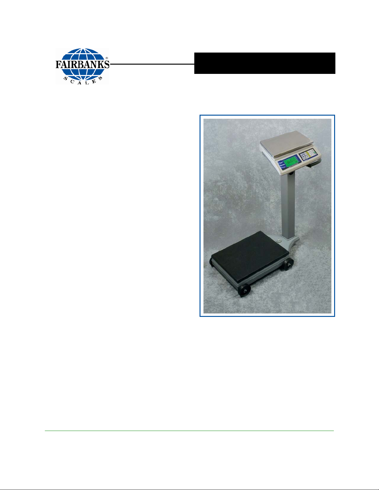
Dual Platform Counting Scale
WITH OMEGA SERIES COUNTING SCALE
MODEL 1129 SERIES
© 2012 by Fairbanks Scales, Inc.
All rights reserved
51300
Revision 1 08/12


Amendment Record
Dual Platform Counting Scale
With Omega Series Counting Scale
Model 1129 Series
Document 51300
Manufactured by Fairbanks Scales Inc.
821 Locust
Kansas City, Missouri 64106
Created 07/12
Revision 1 08/12 Released Product
08/12 3 51300 Rev. 1

Disclaimer
Every effort has been made to provide complete and accurate information in this manual. However,
although this manual may include a specifically identified warranty notice for the product, Fairbanks
Scales makes no representations or warranties with respect to the contents of this manual, and
reserves the right to make changes to this manual without notice when and as improvements are
made.
Fairbanks Scales shall not be liable for any loss, damage, cost of repairs, incidental or consequential
damages of any kind, whether or not based on express or implied warranty, contract, negligence, or
strict liability arising in connection with the design, development, installation, or use of the scale.
Trademarks
All other product names mentioned herein are used for identification purpose only and may be
trademarks and/or registered trademarks of their respective companies
© Copyright 2012
This document contains proprietary information protected by copyright. All rights are reserved; no part
of this manual may be reproduced, copied, translated or transmitted in any form or by any means
without prior written permission of the manufacturer.
08/12 4 51300 Rev. 1

Table of Contents
SECTION 1: GENERAL INFORMATION .................................................................. 7
1.1. Introduction .............................................................................................................. 7
1.1.1. Standard Applications ....................................................................................................... 7
1.2. Description .............................................................................................................. 8
1.2.1. Omega Series Scales ....................................................................................................... 8
1.2.2. Portable Platform Scale .................................................................................................... 8
1.3. Technical Specifications .......................................................................................... 9
1.3.1. Omega Series Basic Specification ................................................................................... 9
1.3.2. Omega Series Scale specifications .................................................................................. 9
1.3.3. Portable Platform Scale Specifications ........................................................................... 10
1.4. Accessories ........................................................................................................... 10
SECTION 2: CUSTOMER SERVICE INFORMATION .............................................. 11
2.1. General Service Policy .......................................................................................... 11
SECTION 3: INSTALLATION ................................................................................... 13
3.1. Tools Required ...................................................................................................... 13
3.2. Wheel and Pillar Assembly .................................................................................... 13
3.3. Mounting Bracket Kit Assembly ............................................................................. 15
3.4. Installing the instrument ......................................................................................... 17
SECTION 4: USER OPERATIONS .......................................................................... 18
4.1. Introduction ............................................................................................................ 18
4.1.1. General Weighing ........................................................................................................... 18
4.2 Front Panel Display and Key Functions ................................................................. 19
4.2.1. LCD Display Definitions .................................................................................................. 19
4.2.2. Keypad Functions ........................................................................................................... 20
4.3. Basic Operational Functions .................................................................................... 22
4.3.1. Gross, Tare and Net Weight ........................................................................................... 22
4.3.2. Counting by Piece Weight .............................................................................................. 23
4.4. Tare Operations ....................................................................................................... 23
4.4.1. Auto Tare Entry ............................................................................................................... 23
4.4.2. Manual Tare Entry Using The Keypad ........................................................................... 24
4.5. Sampling operation ................................................................................................ 24
4.5.1. Enter Piece Weight By Direct Keypad Input ................................................................... 24
4.5.2. Setup Piece Weight By Sampling (Quick Set) ................................................................ 25
4.5.3. Setup Piece Weight by Sampling (Place Item) ............................................................... 26
4.5.4. Setup Piece Weight By Sampling (Remove Item) .......................................................... 27
4.5.5. Setup Piece Weight by Sampling (Re-sample) .............................................................. 28
4.5.6. Auto Re-sample Operation ............................................................................................. 28
4.6. PLU (Part Look UP) operation ............................................................................... 29
4.6.1. Setting Up PLU Keys 1 thru 9 ......................................................................................... 29
4.6.2. Setting Up PLU Keys 0 thru 999 ..................................................................................... 30
4.6.3. Loading PLU 1 thru 9 ...................................................................................................... 31
4.6.4. Loading PLU 0 thru 999 .................................................................................................. 31
4.6.5. Modifying a PLU ............................................................................................................. 32
08/12 5 51300 Rev. 1

Table of Cont ents
SECTION 4: USER OPERATIONS .......................................................................... 18
4.7. More operations ..................................................................................................... 33
4.7.1. Accumulation .................................................................................................................. 33
4.7.2. Recall .............................................................................................................................. 34
4.7.3 Alarm Function ................................................................................................................ 37
4.8. “B Scale” Selection ................................................................................................ 39
SECTION 5: SERVICE AND MAINTENANCE ......................................................... 40
5.1. Basic Cleaning ...................................................................................................... 40
5.2. Troubleshooting ..................................................................................................... 40
5.2.1. Error Code List ................................................................................................................ 40
5.2.2. Solutions ......................................................................................................................... 41
SECTION 6: PARTS ................................................................................................. 42
6.1. Platform and Pillar Assembly Parts List ................................................................. 42
6.2. Platform & Pillar Assembly Diag ram ...................................................................... 43
6.3. Acc 380 Mounting Bracket Parts ............................................................................ 44
6.4. Omega Series Parts List ........................................................................................ 45
6.5. Parts Diagram ....................................................................................................... 46
APPENDIX I: REMOTE PLATFORM WIRING ......................................................... 47
APPENDIX II: RS232C CONNECTION:DB9 (MALE) .............................................. 48
08/12 6 51300 Rev. 1
6 lbs.
15 lbs.
30 lbs.
60 lbs.
100 lbs.
Section 1: General Information
1.1. INTRODUCTION
The 1129 Series Dual Platform Counting Sc al e is available in five (5)
standard models. The difference between these models is the capacity of the local
scale.
The Omega Series Counting Scale is available in five model sizes. This allows
the user to weigh and count their products based on the smallest size of the parts
being weighed.
–
–
–
–
–
The Remote Platform has a capacity of one thousand pounds (1,000 lbs.).
– It is used for weighing larger products, both in capacity and dimensionally.
The Omega Counting Scale is assembled in the same manner for all models.
It is constructed with a mechanical cast iron lever system and base, metal pillar,
Acc 380 Omega Bracket Adapter, and an Omega Counting Scale.
1.1.1. STANDARD APPLICATIONS
Material handling Warehousing Parts distribution
Inventory management Auditing Bag filling
08/12 7 51300 Rev. 1

Section 1: General Information
1.2. DESCRIPTION
1.2.1. Omega Series Scales
The self-contained, local weighing platform and instrument, O m e ga Counting
Scale
platform, perfect for al most any counting scale appli cati on .
Standard units include the following features.
is designed in a rugged ABS plastic enclosure with a stainless steel weighing
– The 9.64” x 13.97” weighing platform can easily accommodate most parts
counting needs.
• Lead-Acid Rechargeable
Battery
S erial Port 1 is dedicated to a Printer, Computer or a Remote Display.
Serial Port 2 is dedicated to Barcode Readers.
• Programmable PLU
(Parts Look Up)
• Dual RS232C Serial
Ports
1.2.2. Portable Platform Scale
The Portable Platform Scale is a remote platform used for bulk w eig hi ng and
counting.
This platform is selected using the front panel of the Omega series Counting
Scale.
The 17.75” x 23.5” weighing platform provides a large space to weigh and
count bulk items up to one thousand pounds (1000 lbs.)
08/12 8 51300 Rev. 1

Section 1: General Information
TEMPERATURE
(0℃
HUMIDITY
1.3. TECHNICAL SPECIFICATIONS
1.3.1. Omega Series Basic Specification
DIGITAL DISPLAY
PLATTER SIZE
DIMENSIONS
NET WEIGHT (KG)
OPERATING
RELATIVE
POWER
INTERFACE
LCD, height 0.6 in (14.5 mm)
6/7/7(Weight / Piece Weight / Total Pieces)
9.64” x 13.97” (245 x 355 mm )
(15.24” x 14.37” x 4.61” (387 x 365 x 117 mm)
8.16 lbs. (3.7 kg)
◌ ۫
32
˚F to +104˚F
Less than 85%
117VAC 50/60Hz +/- 10%
– 9V / 500mA, AC adapter;
Built-in 6V Rechargeable Battery
– 15-20 hours continuous
– 7-10 hours continuous with an external platform
– 14-16 hours recharge time
RS-232C, Serial 1 and Serial 2
to +40℃)
1.3.2. Omega Series Scale specifications
MODEL
MAX . CAPAC ITY
DISPLAYED
DIVISIONS
ACCURACY
Omega Counting Scales
6 lb /
3 kg
0.0002 lb /
0.1 g
1/30000 1/30000 1/30000 1/30000 1/50000
15 lb /
6 kg
0.0005 lb /
0.2 g
30 lb /
15 kg
0.001 lb /
0.5 g
60 lb /
30 kg
0.002 lb /
1 g
100 lb /
50 kg
0.002 lb /
1 g
08/12 9 51300 Rev. 1
Section 1: General Information
MODEL
MAXIMUM CAPACITY
DIVISION SIZE (D)
PLATFORM SIZE
OVERALL LENGTH
WEIGHT
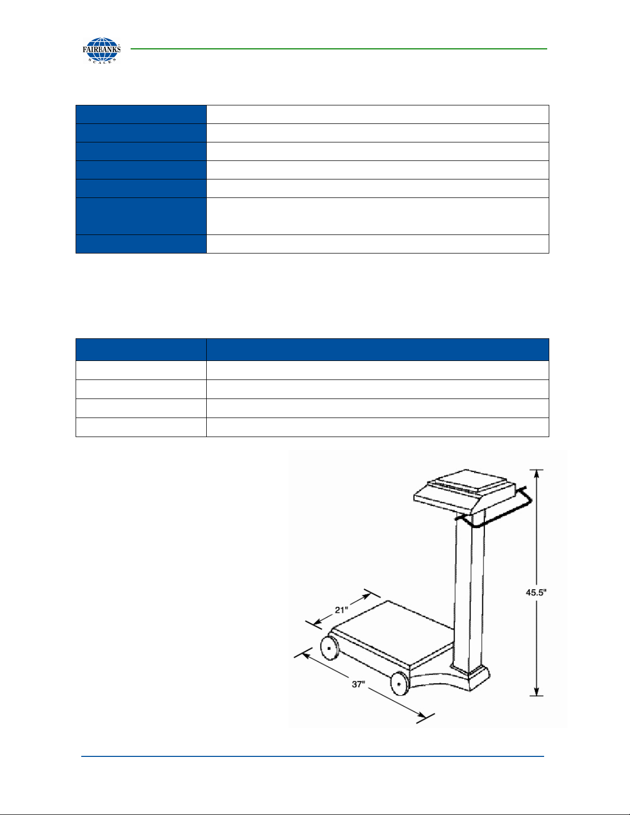
1.3.3. Portable Platform Scale Specifications
Portable Platform Scale
1000 lbs/ 454 kgs
0.5 lbs/ 0.2 kgs
17.75” x 23.5”
37”
CONSTRUCTION
1.4. ACCESSORIES
PRODUCT NO. DESCRIPTION
31701
31789
24482
20483
Base/ Platform/ Wheels: Cast Iron
Column: Fabricated Steel
168 lbs/ 76 kgs
Bar code scanner (Symbol) with hands-free stand
Dust cover (Qty. 5)
2844 series label printer
2844 printer cable (required when a 24482 printer is ordered.)
08/12 10 51300 Rev. 1

Absolutely NO physical, electrical or program modifications other
Section 2: Customer Service Information
2.1. GENERAL SERVICE POLICY
It is the customer/operator's responsibility to ensure the equipment provided by
Fairbanks is operated within the parameters of the equipment's specifications and
protected from accidental or malicious damage.
WARNING!
than selection of standard options and accessories can be made
by customers to this equipment
Repairs are performed by Fairbanks Scales Service Technicians
and Authorized Distri butor Personnel ONLY!
Failure to comply with this poli c y voids al l im pli e d a nd/or written
warranties.
The equipment consists of printed circuit assemblies which must be handled
using ESD handling procedures, and must be replaced as units.
Replacement of individual components is strictly not allowed.
Using electric arc welding can severely damage scale components, such as
digital weight indicators, junction boxes, power supplies, and load cells.
08/12 11 51300 Rev. 1

Section 2: Customer Service Information
All load cells, load cell cables and interconnecting cables used to connect all scale
IMPORTANT INST ALLATION NOTIC E
components shall be locate d a minimum of t hirty-six (36”) inches
distance away
current carrying conductors.
This includes digital weight indicators, junction boxes, and power supplies.
This includes any peripheral devices, such as printers, remote displays, and
auxiliary data entry devices.
Also included is the scale components themselves, such as 120 volt AC, 240
volt AC, 480 volt AC and electric supply of higher voltage wiring runs and
stations, AC power transformers, overhead or buried cables, electric
distribution panels, electric motors, florescent and high intensity lighting
which utilize ballast assemblies, electric heating equipment, traffic light
wiring and power, and relay boxes.
All scale components, including digital weight indicators and peripheral devices are
not designed to operate on internal combustion engine driven electric generators and
other similar equipment.
from all single and multiple phase high energy circuits and electric
NOTE: For more information, please contact a Fairbanks Ser vice
Representative.
08/12 12 51300 Rev. 1

Section 3: Installation
3.1. TOOLS REQUIRED
#1 or Small Slotted Screwdriver
#2 Phillips Screwdriver
10" Adjustable Wrench
Pliers
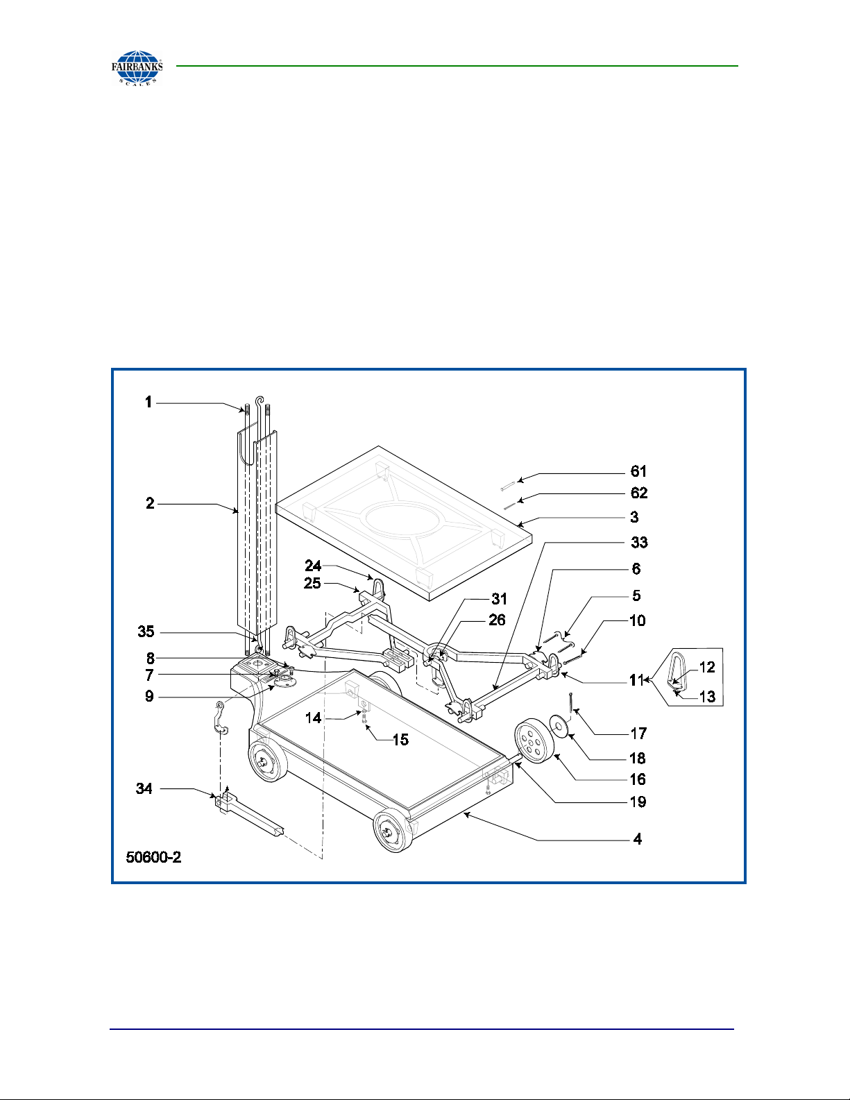
3.2. WHEEL AND PILLAR ASSEMBLY
6. Set the Scale Base Assembly (#4) sideways on the floor.
7. Insert a Cotter Pin (
(#19).
8. Place a Flat Washer (#18) and a Wheel (#16) onto the open end of the axle.
9. Insert the axle's other end through both holes in the base.
10. Place the Second Wheel (#16) onto the axle.
11. Place a Flat Washer (#18) over the axle, and then insert a cotter pin (#17)
through the axle’s small hole.
12. Repeat steps 2-6 for the second axle.
13. With the Scale Base Assembly (#4) in an upside-down position, center the axles
in the base.
14. Insert the Locking Screws (#15) into the tapped holes in the bottom of the base,
tightening the axle into place with the screws.
– Directly under the axle holes.
15. Secure the Lock Nuts (#14).
#17) through the small hole in one end of the First Axle
NOTE: See the diagram on the following page to identify parts in these assembly
instructions.
08/12 13 51300 Rev. 1
Section 3: Assembly
3.2. WHEEL & PILLAR ASSEMBLY, CONTINUED
16. With the Scale Base Assembly (#4) in an upright position Screw the two (2)
Pillar Rods (#1) into the two (2) tapped ho les of the base.
17. Place the Pillar (#2) over the pillar rods.
– The cutouts face to the left and right of the platform
18. Insert the Steelyard Rod (#35) down through the pillar.
– The bent hook is on top, and the loose swivel hook is on the bottom.
08/12 14 51300 Rev. 1
Section 3: Assembly
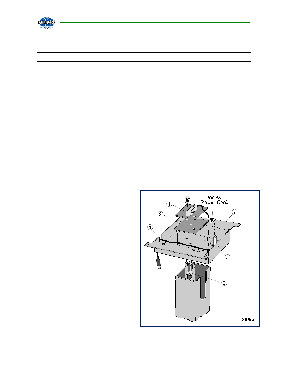
3.3. MOUNTING BRACKET KIT ASSEMBLY
NOTE: The MOUNTING BRACKET KIT ASSEMBLY is partially assembled.
1. With the portable platfor m rig ht-side-up, place the Bracket (#7) on top of the
pillar.
– The two (2) pillar rods must pass through the two (2) holes in the Bracket
(#7).
– The scale display may face any direction on the platform.
2. Place the Stiffener Plate (#8) on the pillar rod, inside the bracket.
3. From the parts envelope, remove the Cable Assembly (#2) which connects the
load cell to the platform.
4. Turn the Jam Nut onto the Linkage Assembly all the way to the bottom of the
threads.
5. Insert the threaded end of the Cable Assembly (#2) into the hole in the bottom of
the Load Cell Assembly (#1).
6. Turn the L inkage Assembly until the top of the threads can be seen in the Load
Cell opening.
7. With a quarter inch (¼”) wrench,
gently tighten the Jam Nut against
the Load Cell.
8. Place the Load Cell Assembly
(#1) on top of the pillar bolts, with
the load cell cable exiting in the
direction to easily connect the cable
to the counting scale.
08/12 15 51300 Rev. 1
 Loading...