

Page 1
CNC 800 T
New Features (Ref.0204in)
Page 2
Version 5.2 (March 1995)
1. P621(4). DIVIDING FACTOR FOR ELECTRONIC HANDWHEEL FEEDBACK SIGNALS
Machine parameter P621(4) is used with P602(4) and P621(5) which indicate the multiplying factor for the electronic handwheel feedback
signals for the 1st and 2nd axis respectively.
Machine parameter P627(1) indicates whether all handwheel feedback signals are to be divided or not.
P621(4)=0 They are not divided.
P621(4)=1 All handwheel feedback signals are divided by two.
Examples for the X axis so the CNC assumes 100 pulses/turn with 25, 50 and 100 line handwheels:
25 line Fagor handwheel: P602(4)=0 and P621(4)=0 25 x 4 / 1 = 100 lines
50 line Fagor handwheel: P602(4)=1 and P621(4)=0 50 x 2 / 1 = 100 lines
100 line Fagor handwheel: P602(4)=1 and P621(4)=1 100 x 2 / 2 = 100 lines
Version 5.6 (June 1996)
1. JOG WITH MASTER HANDWHEEL
With this feature it is possible to jog the machine with the Master Handwheel once the path has been defined.
Requirements:
The control of the "Jog with Master Handwheel" is carried out with the Second Handwheel. Therefore, the machine must have
two electronic handwheels and none mechanical.
Parameter setting:
Machine parameter "P622(6)" indicates whether this feature is being used or not.
P622(6) = 0 "Jog with Master handwheel" is not available.
P622(6) = 1 "Jog with Master handwheel" is available.
As stated above, the control of the "Jog with Master Handwheel" is carried out with the Second Handwheel. Therefore, the
machine must have two electronic handwheels and none mechanical. This means that:
P621(7)=1 The machine does not use mechanical handwheels.
P622(3)=0 It uses two electronic handwheels.
P609(1)=0 The first handwheel is not a FAGOR 100P model.
The Master handwheel is connected via connector "A4". It admits both sine-wave and square-wave differential signals.
This implies setting the following machine parameters as follows:
P621(6) Counting direction of the "Master Handwheel".
P621(3) Feedback units of the "Master Handwheel".
P621(1,2) Feedback resolution of the "Master Handwheel".
P621(5) Feedback multiplying factor for the "Master Handwheel".
Selection:
a) CNC Models: 800TI and 800TGI. From the PLCI.
Once all machine parameters have been set, PLCI output O39 must be used to enable or disable the "Jog with Master Handwheel"
feature.
Parameter P622(6) PLCI output O39 "Jog with Master Handwheel"
P622(6) = 0 ----- Feature not available
P622(6) = 1 O39 = 0 Feature disabled
P622(6) = 1 O39 = 1 Feature enabled
b) CNC Models: 800T and 800TG. Using pin 11 of connector "I/O 1".
Once all machine parameters have been set, the "Jog with Master Handwheel" input (pin 11 of I/O 1) must be used to enable
or disable the "Jog with Master Handwheel" feature.
Parameter P622(6) Pin 11 I/O1 "Jog with Master Handwheel"
P622(6) = 0 ----- Feature not available
P622(6) = 1 Pin 11 at 0Vdc Feature disabled
P622(6) = 1 Pin 11 at 24Vdc Feature enabled
- 2 -
Page 3
Basic Operation. (P622(6)=1, O39=1)
a) When the machine is stopped.
Only the first handwheel is enabled, the second one (Master) is disabled.
Therefore, only the X axis may be jogged with the handwheels.
b) When the machine is running (CNC in Execution).
The axes do not start moving until the Master Handwheel is turned.
The axis feedrate depends on the turning speed of the Master Handwheel. If it stops, the axes also stop.
If the Master Handwheel is turned in the opposite direction, the axes also invert their moving direction (Return Function for one
block only).
c) The "Jog with Master Handwheel" feature may be used with any type of execution, be it a cycle, an ISO-coded program, a
Chamfer, etc.
Usually, with the CNC in execution, the first handwheel is disabled, except for the semi-automatic mode of the automatic operations:
"Taper Turning" and "Rounding".
On both Semi-automatic operations, the Master Handwheel controls the feedrate of the tool path and the First Handwheel will
move the X axis.
"Jog with Master Handwheel" feature disabled. (P622(6)=1, O39=0)
When this feature is disabled, PLC output O39 is set to "0" and the handwheels operate like until now (as on previous versions).
2. DYNAMIC GRAPHICS WHILE IN EXECUTION
Until now, with the 800T CNC, a part program could be simulated (verified) graphically before running it.
From now on, it is also possible to display dynamic graphics of the machining path while in execution.
Requirements:
This application requires a 800TG or 800TGI CNC model (G for graphics).
Operation:
When running an Automatic Operation, a Part program, the ISO-coded program in Automatic or Single Block mode, it is now
possible to display the machining path dynamically in the execution stage.
To do this, once the execution has started, the following keys may be pressed:
[4] The CNC displays the graphics screen.
[3] The CNC shows the "Command, Actual and To-go" coordinates of the axes and, at the top of the screen, the values
of the Arithmetic parameters.
[2] The CNC displays the Following Error (axis lag) in large characters.
[1] The CNC displays the actual axis position in large characters.
[0] The CNC returns to the standard display.
3. WORK ZONE / EXCLUSION ZONE
With this feature it is possible to select a predefined zone as work zone or exclusion zone from the PLCI.
Requirements:
This application requires an 800TI or 800TGI CNC model since one must use outputs O46 and O47 of the PLCI to set the zone
as work zone or exclusion zone.
Parameter setting:
Machine parameter "P622(5)" indicates whether the CNC allows setting a work zone or an exclusion zone.
P622(5) = 0 This feature is not available.
P622(5) = 1 This feature is available.
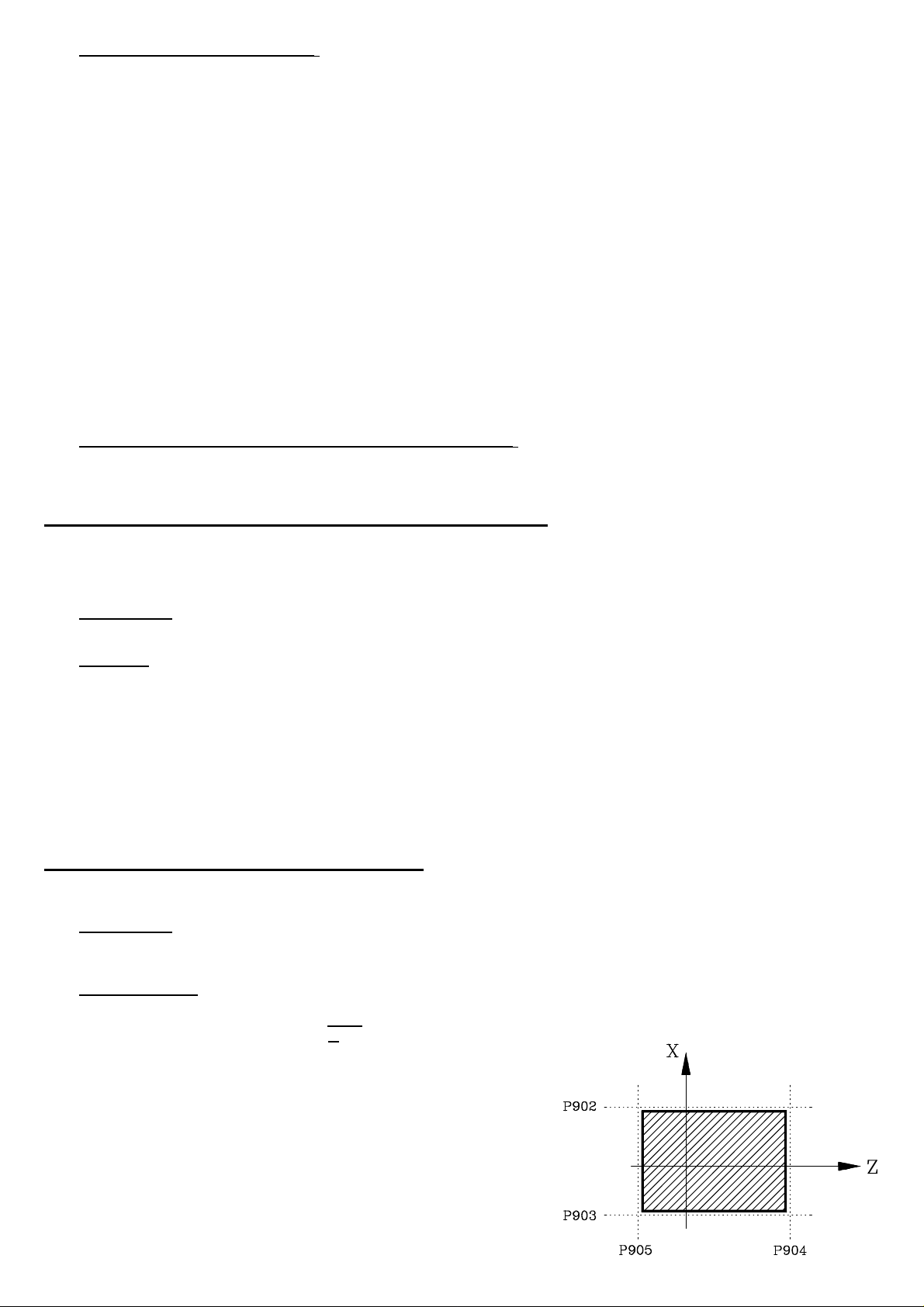
When using this feature "P622(5)=1" the following machine parameters
must also be set to define the zone to be considered either as work zone
or exclusion zone.
P902 Most positive X coordinate
P903 Least positive X coordinate
P904 Most positive Z coordinate
P905 Least positive Z coordinate
The CNC must be turned off and back on in order for the new parameter
values to be assumed.
- 3 -
Page 4
Selection:
Once all machine parameters have been set, PLCI outputs O46 and O47 must be used to select the predefined zone either as a
work zone or as an exclusion zone.
PLCI Output
O46
O46 = 0 O47 = 0 Feature disabled
O46 = 0 O47 = 1 Zone enabled as Work Zone (No-exit zone)
O46 = 1 O47 = 0 Zone enabled as Exclusion Zone (No-entry zone)
O46 = 1 O47 = 1 Feature disabled
Basic operation. "P622(5)=1"
On power-up, the CNC assumes the zone set by machine parameters "P902, P903, P904 and P905".
Nevertheless, the zone boundaries may be changed via part-program by allocating the new values to the following arithmetic
parameters:
P206 Most positive X coordinate
P207 Least positive X coordinate
P208 Most positive Z coordinate
P209 Least positive Z coordinate
The CNC will then assume these new values; but it will not modify the actual settings of machine parameters "P902, P903, P904
and P905".
On the other hand, it must be kept in mind that, on power-up, the CNC will reset these zone boundaries to the values set by machine
parameters.
PLCI Output
O47
"Work Zone or Exclusion Zone" Feature
As described earlier, this predefined zone may be enabled either as a work zone (no-exit) or as an exclusion zone (no-entry) from
the PLCI by means of outputs O46 and O47.
When set as a work zone, the CNC acts as follows:
• The axes cannot be jogged out of this zone by using the jog keys or the handwheels.
• If attempted to do so during execution, the CNC will issue error 67: «X, Z Limit Error»
When set as an exclusion zone, the CNC acts as follows:
• The axes cannot be jogged into this zone by using the jog keys or the handwheels.
• If attempted to do so during execution, the CNC will issue error 67: «X, Z Limit Error»
4. MANUAL SPINDLE GEAR CHANGERS
Operation on previous versions
To manually change the spindle speed range (gear), machine parameter "P601(1)" had to be set to "0".
When the new selected spindle speed "S" involved a gear change, the CNC displayed a message indicating which
range had to be selected.
The operator had to proceed as follows:
1st- Stop the spindle
2nd- Manually change gears
3rd- Restore spindle rotation
4th- Press [ENTER]
The CNC resumed program execution.
Operation on current and future versions
To manually change the spindle speed range (gear), machine parameter "P601(1)" must set to "0".
When the new selected spindle speed "S" involves a gear change, the CNC displays a message indicating which range
has to be selected.
The operator must proceed as follows:
1st- Manually change gears
2nd- Press [ENTER]
The CNC restores spindle rotation and resumes program execution.
- 4 -
Page 5
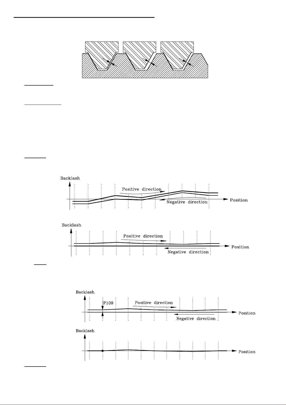
5. VARIABLE BACKLASH COMPENSATION
Until now, the 800T CNC allowed for a single leadscrew backlash compensation.
From now on, it is also possible to compensate for motion-reversal backlash depending on the particular backlash areas of the
axes.
Requirements:
The leadscrew error compensation tables are now used for leadscrew error compensation and for this "Variable Backlash
Compensation" (at the same time).
Parameter setting:
Machine parameters "P622(7)" and "P622(8)" indicate whether this feature is available or not.
P622(7) = 0 Not available for the Z axis.
P622(7) = 1 Available for the Z axis.
P622(8) = 0 Not available for the X axis.
P622(8) = 1 Available for the X axis.
In order to use "Variable Backlash Compensation", regular leadscrew compensation must also be activated.
P605(2) = 0 X axis Leadscrew error compensation (0= No, 1= Yes)
P605(1) = 0 Z axis Leadscrew error compensation (0= No, 1= Yes)
Operation:
The first 15 points of the table are for the positive direction and the other 15 for the negative direction.
When compensating for leadscrew error, the amount of backlash is the difference between both graphs.
When leadscrew error compensation is not to be used, all the values of one of the tables must be set to "0"; thus, the other graph
will correspond to the leadscrew backlash.
Notes: • Both graphs must meet all the requirements of the leadscrew error compensation tables.
• One of these requirements states that the Machine Reference Zero (home) must be assigned an error of "0".
• If the leadscrew has some backlash at this Machine Reference Zero point, that amount of backlash must be allocated
to machine parameter P109 or P309 (Backlash for the X axis or Z axis) and all the remaining points of the table must
be offset by that amount.
Example:
Operation:
When using "Variable Backlash Compensation", the CNC operates with leadscrew error compensation and, therefore, it applies
at all times the backlash compensation set in the table for that point and in the machining direction.
When the axis movement is reversed, the CNC swaps graphs restoring or applying the amount of backlash compensation and
direction corresponding to that point.
- 5 -
Page 6

Version 5.7 (July 1996)
1. WORK ZONE / EXCLUSION ZONE DETECTION
When using this feature, the CNC prevents the axes from exiting or entering this zone while jogging them with either the jog keys or
the electronic handwheel.
The operator might suspect a malfunction since the CNC does not issue any message. From this version on, in these cases, the CNC
will behave as follows:
* When the zone has been set as a Work Zone, the CNC will set PLCI input I46 high when trying to exit the selected zone.
* When the zone has been set as a Work Zone, the CNC will set PLCI input I46 high when trying to enter the selected zone.
2. RESUME EXECUTION AT MID-PROGRAM
If while a part, the program is interrupted (due to a power failure, etc.), it is now possible to resume execution from the interrupted program
on. This way, there is no longer need to repeat the whole program, thus saving considerable amount of time.
To resume program execution, follow these steps:
1st Select the DRO mode, the one appearing on CNC power-up after the "General Test Passed".
In this mode, no cycle appears selected.
2nd Press [RECALL] to open the part-programs window.
3rd Select the part that was running. Use the up and down arrow keys to position over the desired part program and press
[RECALL] .
4th Use the up and down arrow keys to select the operation being interrupted and press
The CNC will executed the selected operation and it will resume the part-program running it to the end.
Version 6.1 (January 1997)
1. NEW LANGUAGES (Taiwanese and Portuguese)
Machine parameter P99 P99 = 5 Portuguese P99 = 6 Taiwanese
2. MODIFICATIONS ON THE OPERATION WITH A MASTER HANDWHEEL
The operation with the master handwheel is now as follows:
a) When the machine is stopped.
Only the first handwheel is enabled, the second one (master) does not work.
Therefore, only the X axis can be jogged with a handwheel.
b) When the machine is running (CNC in Execution).
Only the Master handwheel is enabled, the first handwheel does not work.
The axes start moving when turning the Master Handwheel.
The feedrate of the axes depend on the turning speed of the Master Handwheel
When the handwheel stops, the machine also stops.
When the Master Handwheel is turned in the opposite direction, the CNC also reverses the moving direction (Retrace Function
of a single block).
c) Semiautomatic Rounding Operation
The Semiautomatic Rounding operation starts when turning the Master Handwheel.
When stopping the Master Handwheel, the execution is interrupted.
When turning the Master handwheel again, execution is resumed. The turning direction of the handwheel cannot be changed.
When the operation is over, the CNC ignores the turning of the Master Handwheel for 1.4 seconds. Thus preventing another
operation from being started.
After this time, when the Master Handwheel is turned, the CNC starts executing a new operation in the indicated direction.
- 6 -
Page 7
d) Semiautomatic Taper Turning Operation
The Semiautomatic Taper Turning Operation starts when turning the Master Handwheel.
When stopping the Master Handwheel, the execution is interrupted.
When turning the Master handwheel again, execution is resumed.
When turning the Master Handwheel in the opposite direction, the operation is over. A new turn of the Master Handwheel in
any direction implies the execution of a new operation in the indicated direction.
3. SOFTWARE VERSION OF THE CNC
From this version on, when accessing the EPROM checksum screen,
[Auxiliary Modes] [Special Modes] [8]
The CNC will show the checksum of each EPROM and the Software version of the CNC. For example: Version 6.1
Version 6.4 (May 1997)
1. TOOL CHANGE INDICATOR FOR THE PLC (I97)
On machines with a manual tool changer, when the CNC detects that the tool must be changed, it interrupts the execution and it displays
a message for the operator to proceed with the tool change.
Certain precautions must be taken sometimes when changing tools. Those conditions must be handled by the PLC.
Therefore, from this version on, when the CNC displays the tool change warning message, it also activates the PLC input I97 and
it cancels it when the message is removed.
Version 6.6 (November 1997)
1. HANDLING FEEDBACK SYSTEMS WITH CODED Io (semi-absolute)
Machine parameters
P608(5), P608(8) Type of Home marker signal of the feedback system. X, Z axes. (0 = normal "Io", 1 = coded "Io")
P608(3), P608(6) Period of the coded Io signal. X, Z signal. (0 = 20mm Period, 1 = 100 mm Period)
P608(4), P608(7) Increasing Io sequence with positive or negative count. X, Z axes
(0 = Increasing Io with positive count, 1 = increasing Io with negative count)
Scale
Regla P608 (5) P608(3) P608(4) Regla P608 (5) P608(3) P608(4)
COS
COC
COX
COVS
COVC
COVX
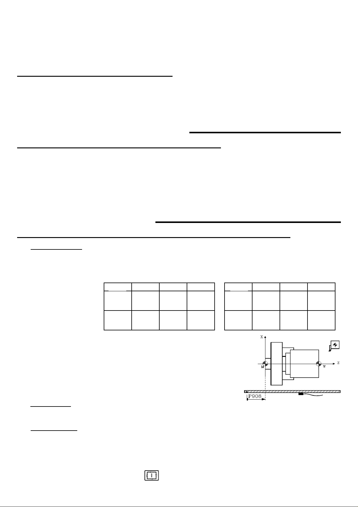
P908, P909 Scale offset or Home position (Machine Reference: M) with
respect to the Scale "zero" point. X, Z axes.
Linear transducers (scales) with coded Io have a graduated
scale with their own Scale "zero" point. Therefore, a 20 mm or
100 mm move is enough to know the axis position with respect
to the Scale "zero" point.
1
1
1
1
1
1
0
0
0
0
0
0
1
0
0
1
0
0
Scale
MOVS
MOVC
MOVX
FOT
FOS
FOC
1
1
1
1
1
1
0
0
0
1
1
1
0
0
0
0
0
0
Reference point.
When the feedback system has a coded Io, this point is only used when leadscrew error compensation is needed. The leadscrew
error on this point must be "0".
Scale offset setting
The scale offset must be adjusted on one axis at a time. The following procedure is recommended:
* Indicate by parameters "P600(7) & P600(6)" the up or down flank of the marker pulse (Io) of the feedback system.
* Indicate by parameters "P618(8) & P618(7)" the home searching direction for the axes.
* Set parameters "P807 and P808" with the home searching feedrate for the axes.
* Set parameters " P908 and P909" to "0" (scale offset).
Position the axis at the right position and execute the home search command for that axis..
[X] or [Z], [up arrow] keys and
When done with the home search, the CNC will display the axis position with respect to the scale's Zero point.
- 7 -
Page 8

* After moving the axis to Machine Reference Zero point (home) or up to a known position with respect to home, Jot down the
position reading of the CNC for that known position.
The value to allocate to the machine parameter setting the scale's offset must be calculated with the following formula:
Value = CNC reading at that point - Home coordinate of that point
Example for the X axis: If the known position is physically located at 230 mm from Machine Reference Zero (home) and the
CNC shows that its position is 423.5 mm, the scale offset will be:
Machine parameter P908 = 423.5 - 230 = 193.5 mm.
* After setting the machine parameter with this value, press the [RESET] key so that value is assumed by the CNC.
* A new home search must be carried out for the proper values to be assumed for that axis.
2. THREADING WITH CONSTANT PENETRATION PASSES
From this version on, the penetration of each pass will depend on the sign assigned to parameter ∆∆
When ∆∆ positive, the penetration of each pass depends on the corresponding pass (∆∆ n)
With ∆∆ negative, the penetration passes remain constant with the absolute value of parameter ∆∆
3. GENERATING AN ISO-CODED PROGRAM
With this CNC, the ISO code (low level) for an operation or a part-program may be generated.
To use this feature, machine parameter "P623(2)" must be set to "1".
This ISO program always has the number: 99996 and can be stored either at the CNC or at a PC.
Program 99996 is a special user program in ISO code and can be:
Generated from an operation or a part-program.
Edited at the CNC itself via menu option: "Auxiliary Modes - Edit program 99996"
Loaded into the CNC after being generated at a PC.
Generating the ISO program (99996) at the CNC.
This CNC has 7 K of memory space to store program 99996. If the generated program is larger than that, the CNC will issue the
relevant error message.
To generate program 99996, proceed as follows:
* If it is an operation, select or define the desired operation.
* If it is a part-program, select the desired one in the part-program directory and place the cursor on its header ("PART 01435".
A listing of the operations it consists of must appear).
* Press the keystroke sequence: [AUX] [7]. The CNC will show the graphic simulation screen.
* Press . The CNC starts simulating the part and generating its ISO-coded program 99996.
* When done with the simulation, program 99996 stored in CNC memory will contain all simulated blocks in ISO code.
Generating the ISO program (99996) at a PC
Usually, the 99996 program generated from a part-program exceeds the available memory space of the CNC.
By using "DNC30", this program may be generated at a PC.
To do this, proceed as follows:
* Activate DNC communications and execute the DNC30 program at the PC.
* Select at the PC the menu option: "Program Management - Receive Digitizing".
* At the CNC, select the operation or place the cursor on the part-program header ("PART 01435"). A listing of the operations
it consists of must appear).
* Press [AUX] [8]. The CNC will display the graphic simulation screen.
* Press . The CNC starts simulating the part and generating program 99996.
* When done with the simulation, the 99996 program generated at the PC will contain all the blocks simulated by the CNC in
ISO code.
This program can be executed at the CNC through the menu option: "Execute infinite program" of the DNC30.
4. MACHINE SAFETY REGULATION
This CNC offers the following features to comply with machine safety regulations.
Enabling of the CYCLE START key from the PLC
This feature is available when machine parameter "P619(7)=1"
PLC output O25 indicates whether the CYCLE START key is enabled (=1) or not (=0)
- 8 -
Page 9

Axes movements affected by Feed-Hold. (It was already available)
Feed-Hold input, pin 15 of connector I/O 1, must be normally high.
If while moving the axes, the Feed-Hold input is brought low, the CNC keeps the spindle turning and stops the axes with 0V or
velocity command (analog signal) and keeping their enables ON.
When this signal is brought back up, the CNC will resume the movement of the axes.
Axes jogging feedrate limited by PLC.
This feature is available when machine parameter "P619(7)=1"
When activating PLC output O26, the CNC assumes the feedrate set by machine parameter "P812"
Handwheel managed by the PLC.
Machine parameter "P623(3)" indicates whether the axes movements with handwheels are affected by Feed-Hold (=1) or not (=0)
Machine parameter "P622(1)" indicates whether the multiplying factor indicated by the MFO switch position is applied (=0) or
the one indicated by the PLC outputs O44 and O45 (=1) (already available)
Spindle control from the PLC.
This feature is available when "P619(7)=1"
Output O27 =1 "tells" the CNC to apply the spindle analog voltage set by the PLC. The value of this analog signal is set at register
R156 and sent to the CNC by mark M1956.
R156= 0000 1111 1111 1111 => + 10V. R156= 0001 1111 1111 1111 => - 10V.
R156= 0000 0111 1111 1111 => + 5V. R156= 0001 0111 1111 1111 => - 5V.
R156= 0000 0011 1111 1111 => + 2,5V. R156= 0001 0011 1111 1111 => - 2,5V.
R156= 0000 0000 0000 0000 => + 0V. R156= 0001 0000 0000 0000 => - 0V.
Also, PLC output O43, lets you control the rotation of the spindle. (Already available).
It must be normally low.
If it is brought up, the CNC stops the spindle.
When it is brought back up, the CNC restarts the spindle.
Information for the PLC on the status of the machine reference (home) search
I88 Home search in progress.
I100 X axis home search done.
I101 Z axis home search done.
Additional CNC information for the PLC
R120 The Lower half of this register indicates the code pressed.
This value is maintained for 200 milliseconds unless another key is pressed before then.
This register may be canceled from the PLC after being processed.
R121 bit 1 Indicates that the Turning operation is selected (=1)
bit 2 Indicates that the Facing operation is selected (=1)
bit 3 Indicates that the Taper Turning operation is selected (=1)
bit 4 Indicates that the Rounding operation is selected (=1)
bit 5 Indicates that the Threading operation is selected (=1)
bit 6 Indicates that the Grooving operation is selected (=1)
bit 7 Indicates that the Profiling operation is selected (=1)
bit 8 Indicates that the Auxiliary Modes option is selected (=1)
bit 9 Indicates that the Tool Calibration option is selected (=1)
bit 10 Indicates that the Multiple Drilling operation is selected (=1)
bit 11 Indicates that the Simple Drilling / Tapping operation is selected (=1)
bit 12 Indicates that the Slot milling (keyway) operation is selected (=1)
bit 13 Indicates that the Tool Inspection mode is selected (=1)
bit 14 Indicates that the Graphic Simulation mode is selected (=1)
bit 16 Indicates that the mode for the following cycle parameters: "Finishing pass, finishing feedrate, finishing tool
and safety distances on X and Z " is selected (=1)
- 9 -
Page 10
Version 6.8 (March 1998)
1. NEW LANGUAGES (SWEDISH AND NORWEGIAN)
The languages that can be selected with machine parameter P99 are:
Spanish .......(P99=0) German ....... (P99=1) English ........(P99=2) French ........ (P99=3) Italian..........(P99=4)
Portuguese..(P99=5) Taiwanese... (P99=6) Swedish ......(P99=7) Norwegian .. (P99=8)
2. 1000 LINE ENCODER AS 1250 LINE AS ENCODER
This feature permits the CNC adapt a 1000 line encoder to be used as 1250 line encoder.
P623(7) Adapts the X axis feedback encoder (0=No, 1=Yes)
P623(8) Adapts the Z axis feedback encoder (0=No, 1=Yes)
A typical case: Having a 1000 line for a 5 mm pitch ballscrew .
The calculations necessary to set the axis resolution will be made with the selected pulses (1000 or 1250)
3. CROSS COMPENSATION
Cross compensation is used for compensating the measuring error suffered by the X axis when moving the Z axis.
P623(6) Cross compensation applied on to the X axis (0=No, 1=Yes)
When using cross compensation, no leadscrew compensation may be applied on the X axis (only on to the Z axis) since its
corresponding table is being used for cross compensation with the following values:
P00 = X: ?????.??? P01 = DX: ????.???
in order to properly apply cross compensation, set: P605(2)=1 and P623(6)=1.
Note: The cross compensation table must meet the same requirements as those for the leadscrew error compensation. See section
3.8.4 of the installation manual.
4. PLCI. INPUT I104
When the Feedrate Override Switch on the operator panel is set on one of the handwheel positions (x1, x10, x100), input I104 is set
to "1".
Version 6.9 (February 1999)
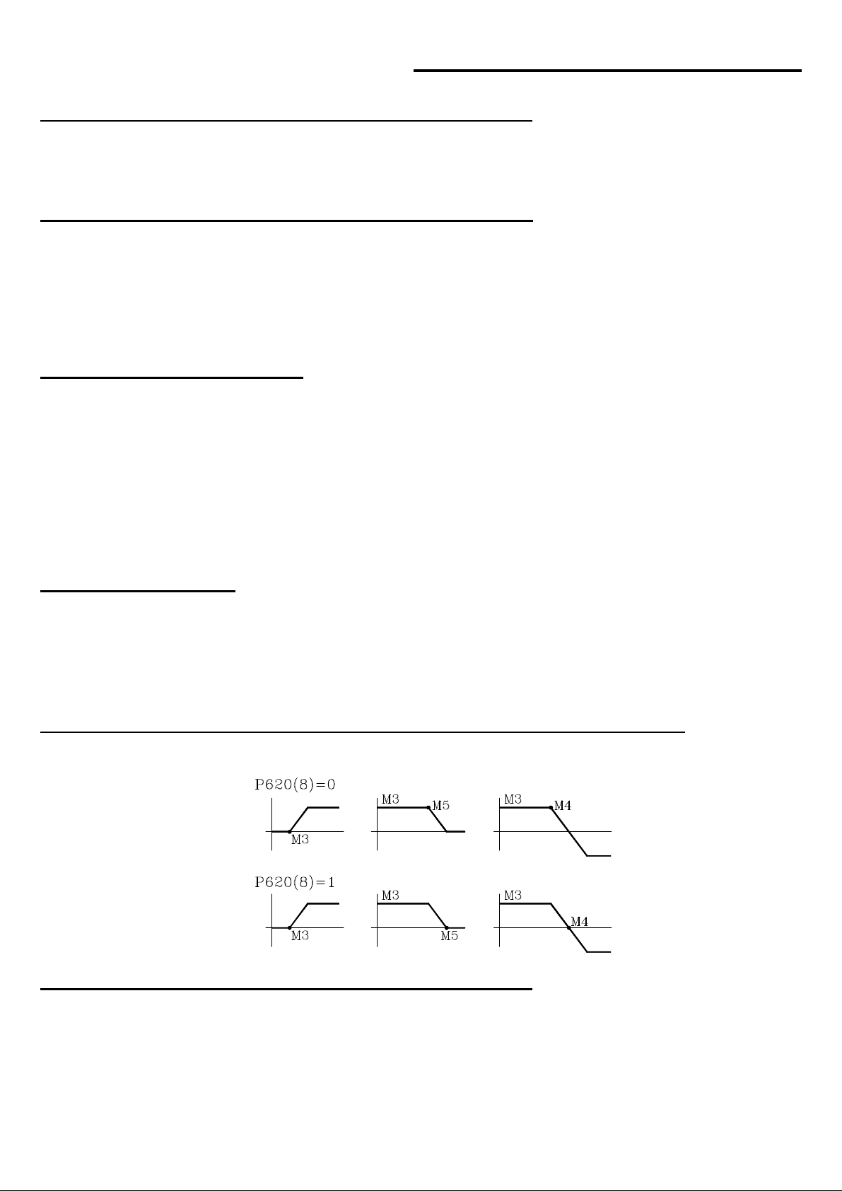
1. NEW MACHINE PARAMETER ASSOCIATED WITH M FUNCTIONS
Machine parameter "P620(8)" indicates when the M functions M3, M4 and M5 are to be output during the acceleration and deceleration
of the spindle.
2. CANCEL TOOL OFFSET DURING TOOL CHANGE
From this version on, it is possible to execute, within a subroutine associated with the tool, a "T.0" type block to cancel the tool offset.
This allows to move to a specific position without having to do cumbersome calculations.
It is only possible to cancel (T.0) or change (T.xx) the tool offset. The tool cannot be changed (Txx.xx) within the subroutine associated
with the tool.
- 10 -
Page 11

3. X1 FACTOR FOR FEEDBACK PULSES
Machine parameters P620(5) and P620(6) are used together with P602(6) and P602(5) which indicate the multiplying factor of the
feedback pulses for the X and Z axes respectively.
They indicate whether x1 factor is applied to the feedback pulses (=1) or not (=0).
P620(5)=0 and P620(6)=0 the x1 factor is NOT applied
P620(5)=1 and P620(6)=1 the x1 factor is applied
Example: We would like to obtain a 0.01 mm resolution with a square signal encoder mounted on the X axis having a leadscrew pitch
of 5mm/turn.
Number of Encoder pulses = leadscrew pitch / (multiplying factor x Resolution)
Con P602(6)=0 and P620(5)=0 x4 multiplying factor Number of pulses = 125
Con P602(6)=1 and P620(5)=0 x2 multiplying factor Number of pulses = 250
Con P602(6)=0 and P620(5)=1 x2 multiplying factor Number of pulses = 250
Con P602(6)=1 and P620(5)=1 x1 multiplying factor Number of pulses = 500
Version 6.10 (March 2002)
1. FEEDBACK FACTOR.
The resolution of the axis is determined by the leadscrew pitch and the number of pulses of the encoder mounted on the motor.
Sometimes, the resolution resulting from the available leadscrew / encoder combination does not match any of the resolution values
allowed for the machine parameters (1, 2, 5, 10 microns or ten-thousandths of an inch).
Example: With a 6 mm/turn leadscrew pitch and a 2500 line encoder, the resulting resolution values are:
Resolution = Leadscrew pitch / ( Nr of encoder pulses x multiplying factor).
With x1 multiplying factor 2.4 micron resolution
With x2 multiplying factor 1.2 micron resolution
With a x4 multiplying factor 0.6 micron resolution
A new axis machine parameter is now available to solve these cases and it is referred to as Feedback Factor in order to adapt the resulting
resolution to the existing setup.
P819 Feedback factor for the X axis P820 Feedback factor for the Y axis P821 Feedback factor for the Z axis
Values between 0 and 65534, a "0" value means that this feature is not being used.
Use the following formula to calculate the "Feedback factor":
Feedback Factor = (Gear ratio x Leadscrew Pitch / Encoder pulses) x 8.192
Examples: Gear ratio 1 1 2 1
Leadscrew Pitch 4000 6000 6000 8000 (microns)
Encoder 2500 2500 2500 2500 (pulses/turn)
Feedback factor 13,107.2 19,660.8 39,321.6 26,214.4
The machine parameters only admit integers, but the Feedback Factor sometimes may have decimals. In those cases, set the machine
parameter to the integer part of that value and use the leadscrew error compensation table to make up for the decimal part.
The values for this table are calculated using the following formula:
Leadscrew position = Leadscrew error (microns) x Integer portion of feedback factor /Decimal portion of feedback factor
In this case: Gear ratio = 1 Pitch = 6000 Encoder = 2500
Feedback factor = 19,660.8 Machine parameter = 19660
For leadscrew error of 20 microns Leadscrew position = 20 x 19,660 / 0.8 = 491,520
The following table is obtained by using this calculation.
Leadscrew position Amount of error at that position
P0 = -1966,000 P1 = -0.080
P2 = -1474,500 P3 = -0.060
P4 = -983,000 P5 = -0.040
P6 = -491,500 P7 = -0.020
P8 = 0 P9 = 0
P10 = 491,500 P11 = 0.020
P12 = 983,000 P13 = 0.040
P14 = 1472,500 P15 = 0.060
P16 = 1966,000 P17 = 0.080
- 11 -
Page 12
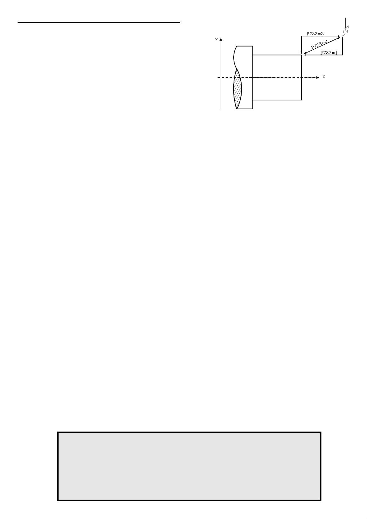
2. PART APPROACHING MOVEMENTS
From this version on, there is a new machine parameter to specify the part
approaching and leaving movements.
P732=0 Like until now, interpolated movement
P732=1 Paraxial movements (one axis at a time) .
Approach: X - Z Exit: Z - X
P732=2 Paraxial movements (one axis at a time) .
Approach: Z - X Exit: X - Z
Headquarters (SPAIN): Fagor Automation S. Coop.
Bº San Andrés s/n, Apdo. 144
E-20500 Arrasate - Mondragón
Tel: +34-943-719200/039800
Fax: +34- 943-791712
+34-943-771118 (Service Dept.)
www.fagorautomation.com
E-mail: info@fagorautomation.es
- 12 -
Page 13

FAGOR 800T CNC
OPERATING
MANUAL
Ref. 9701 (in)
Page 14

ABOUT THE INFORMATION IN THIS MANUAL
This manual is addressed to the machine operator.
It includes the necessary information for new users as well as advanced subjects for those who
are already familiar with the 800T CNC product.
It may not be necessary to read this whole manual. Consult the list of "New Features and
Modifications".
This manual explains all the functions of the 800T CNC family. Consult the Comparison Table
for the models in order to find the specific ones offered by your CNC.
Chapters 1, 2, 3 and 4 show how to operate with this CNC.
This CNC permits machining the "Profile of a part", chapter 6, or perform a series of
"Automatic Operations" detailed in chapter 5. All these machining operations may be carried
out in two ways:
* "Semi-automatically", where the operator controls the movements.
* "Automatically" (Cycle level), where the operator programs the operation and the CNC
executes it automatically.
Chapter 7 "Working with Part-programs" shows how to create parts consisting of Profiles and
Automatic Operations. The Part-programs are stored in the internal CNC memory and may be
sent out to a peripheral device or PC.
Chapter 8 "Programming examples" shows how to edit several part-programs.
There is also an appendix on error codes which indicates some of the probable reasons which
could cause each one of them.
Notes:
The information described in this manual may be subject to variations due to
technical modifications.
FAGOR AUTOMATION, S.Coop. Ltda. reserves the right to modify the contents
of the manual without prior notice.
Page 15

INDEX
Section Page
Comparison Table for FAGOR 800T CNC models ......................................................ix
New features and modifications ...................................................................................xiii
INTRODUCTION
Safety Conditions ...........................................................................................................3
Material Returning Terms ............................................................................................. 5
Fagor Documentation for the 800M CNC ...................................................................6
Manual Contents ............................................................................................................7
Chapter 1. CONCEPTS
1.1 CRT description .............................................................................................................1
1.2 Keyboard description .................................................................................................... 3
1.2.1 Keys for automatic operations ......................................................................................5
1.2.2 Special keystroke sequences.........................................................................................6
1.2.3 Operator Panel ................................................................................................................7
1.3 Display units (mm/inches) ............................................................................................8
1.3.1 X axis display units (radius/diameter) ......................................................................... 8
1.4 Reference systems..........................................................................................................9
1.4.1 Home search ...................................................................................................................9
1.4.2 Zero preset ......................................................................................................................10
1.4.3 Coordinate preset ...........................................................................................................10
1.5 Operation in incremental mode .....................................................................................11
Chapter 2. BASIC OPERATIONS
2.1 Axis feedrate setting ......................................................................................................1
2.2 Work tool selection ........................................................................................................2
2.2.1 Live tool ..........................................................................................................................3
2.3 Axes jog .......................................................................................................................... 4
2.3.1 Continuous jog ...............................................................................................................4
2.3.2 Incremental jog ..............................................................................................................5
2.3.3 Axes jog via electronic handwheel ...............................................................................6
2.4 Beginning point (BEGIN) and end point (END) ..........................................................7
2.4.1 Begin and End point setting .......................................................................................... 8
2.4.2 Positioning at Begin or End points ...............................................................................9
2.5 Activating/deactivating external devices ....................................................................10
Page 16

Section Page
Chapter 3. AUXILIARY FUNCTIONS
3.1 Millimeters <-> inches ..................................................................................................1
3.2 Radius <-> diameter....................................................................................................... 2
3.3 F mm(inches)/min <-> F mm(inches)/rev ....................................................................2
3.4 Tool .................................................................................................................................3
3.4.1 Tool table ........................................................................................................................3
3.4.1.1 Modification of tool dimensions................................................................................... 5
3.4.2 Tool calibration ..............................................................................................................6
3.4.3 Tool inspecton ................................................................................................................ 7
3.4.4 Tool offset modification ................................................................................................8
3.5 Cycle finishing pass/Safety distance ............................................................................9
3.6 Other automatic operations ...........................................................................................11
3.7 Auxiliary modes .............................................................................................................12
3.8 Peripherals ......................................................................................................................13
3.8.1 Peripheral mode ............................................................................................................. 13
3.8.2 DNC communications ....................................................................................................14
3.9 Lock/unlock....................................................................................................................15
3.10 Execution / Simulation of program P99996 .................................................................16
3.10.1 Execution of program P99996 ......................................................................................17
3.10.1.1 Tool inspection............................................................................................................... 18
3.10.1.2 Execution modes ............................................................................................................19
3.10.1.3 CNC reset ........................................................................................................................19
3.10.1.4 Displaying program blocks ...........................................................................................19
3.10.1.5 Display modes ................................................................................................................20
3.10.2 Simulation of program P99996 ..................................................................................... 22
3.10.2.1 Zoom function ................................................................................................................23
3.11 Editing program P99996................................................................................................24
Chapter 4. SPINDLE
4.1 Spindle operating mode selection.................................................................................1
4.2 Spindle in RPM ............................................................................................................... 2
4.3 Constant Surface Speed (CSS) ......................................................................................3
4.3.1 Constant Surface Speed Limit .......................................................................................3
4.4 Spindle speed range change ..........................................................................................4
4.4.1 Manual spindle range change .......................................................................................4
4.4.2 Automatic spindle range change...................................................................................4
4.5 Clockwise spindle rotation ............................................................................................5
4.6 Counter-clockwise spindle rotation.............................................................................. 5
4.7 Spindle stop ....................................................................................................................5
4.8 Spindle orientation .........................................................................................................6
Page 17

Section Page
Chapter 5. AUTOMATIC OPERATIONS
5.1 Introduction ....................................................................................................................1
5.1.1 Automatic operations in semi-automatic mode ...........................................................1
5.1.2 Automatic operations in automatic mode (Cycle) .......................................................2
5.1.2.1 Machining conditions ....................................................................................................2
5.1.3 Simulation.......................................................................................................................4
5.1.3.1 Zoom function ................................................................................................................5
5.1.4 Execution ........................................................................................................................6
5.1.4.1 Tool inspection...............................................................................................................7
5.2 Turning ...........................................................................................................................8
5.2.1 "Semi-automatic" turning ..............................................................................................8
5.2.2 "Automatic" turning (Cycle mode) ...............................................................................9
5.3 Facing..............................................................................................................................12
5.3.1 "Semi-automatic" facing................................................................................................ 12
5.3.2 "Automatic" facing (Cycle mode)................................................................................. 13
5.4 Taper turning ..................................................................................................................15
5.4.1 "Semi-automatic" taper turning .................................................................................... 15
5.4.2 "Automatic" taper turning (Cycle mode) ..................................................................... 16
5.5 Rounding ........................................................................................................................ 19
5.5.1 "Semi-automatic" rounding ........................................................................................... 19
5.5.2 "Automatic" rounding (Cycle mode) ............................................................................21
5.5.3 "Automatic" profile rounding ....................................................................................... 25
5.6 Threading ........................................................................................................................31
5.6.1 "Semi-automatic" threading ..........................................................................................31
5.6.2 "Automatic" threading (Cycle mode) ...........................................................................32
5.7 Grooving .........................................................................................................................35
5.8 Simple drilling. Tapping ................................................................................................38
5.8.1 Programming examples ................................................................................................. 41
5.9 Multiple drilling .............................................................................................................42
5.10 Slot milling .....................................................................................................................45
5.11 Usage of the safety distance ..........................................................................................48
Chapter 6. PROFILES
6.1 Profile in "semi-automatic" mode .................................................................................2
6.1.1 Point storage ...................................................................................................................2
6.1.2 Point-to-point movement...............................................................................................3
6.1.3 Special features ..............................................................................................................4
6.2 Profile in automatic (Cycle) mode ................................................................................5
6.2.1 Profile definition ............................................................................................................10
Page 18

Chapter 7. WORKING WITH PART-PROGRAMS
7.1 Access to the part-program table .................................................................................. 1
7.2 Part-program selection ..................................................................................................2
7.3 Part-program editing ......................................................................................................2
7.4 Part-program simulation ................................................................................................4
7.4.1 Zoom function ................................................................................................................5
7.5 Part-program execution .................................................................................................6
7.5.1 Execution of a previously stored operation .................................................................7
7.5.2 Tool inspection............................................................................................................... 8
7.6 Part-program modification ............................................................................................9
7.7 Part-program deletion ....................................................................................................10
7.8 Peripherals ......................................................................................................................11
7.8.1 Peripheral mode ............................................................................................................. 11
7.8.2 DNC communications ....................................................................................................12
7.9 Lock/Unlock ...................................................................................................................13
Chapter 8. PROGRAMMING EXAMPLES
ERROR CODES
Page 19
COMPARISON TABLE
FOR FAGOR 800T
CNC MODELS
Page 20
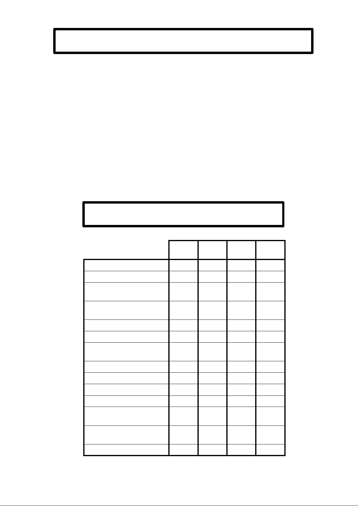
AVAILABLE 800T CNC MODELS
Compact model with 8" amber CRT.
Modular model with 9" amber Monitor.
Consisting of Central Unit, Monitor and Keyboard.
Modular model with 14" Color Monitor
Consisting of Central Unit, Monitor and Keyboard.
TECHNICAL DESCRIPTION
X, Z axes control
Spindle control
Spindle in RPM
Constant Surface Speed (CSS)
Spindle Orientation
Tools
Tool Compensation
Live Tool
Electronic Handwheels
RS 232C Communications
Integrated PLC (PLCI)
ISO-coded program editing
(P99996)
800-T 800-TI 800-TG 800-TGI
l l l l
l l l l
l l l l
l l l l
l l l l
32 32 32 32
l l l l
l l l l
2 2 2 2
l l l l
l l
l l l l
Execution of ISO-coded
program (P99996)
Graphics
l l l l
l l
Page 21
NEW FEATURES
AND
MODIFICATIONS
Date: April 1993 Software Version: 2.1 and newer
FEATURE AFFECTED MANUAL AND SECTION
Rapid jog depending on position of
Feedrate Override Switch Operating Manual Section 2.3.1
Tool for the finishing pass Installation Manual Section 3.5
Operating Manual Section 3.5
Handwheel movement limited to maximum Operating Manual Section 2.3.3
allowed F
Control of software travel limits when using a
handwheel
Display format for S Installation Manual Section 6
Possibility to activate/deactivate outputs O1,
O2, O3 after interrupting the program
Automatic operation "Profile Rounding" Operating Manual Section 5.5.3
Profiles Operating Manual Chapter 6
Date: October 1993 Software Version: 3.1 and newer
FEATURE AFFECTED MANUAL AND SECTION
Spindle acc./dec. Operating Manual Chapter 6
RPM Limitation when operating in CSS Operating Manual Section 4.3.1
Spindle orientation Installation Manual Section 6.4.1
Operating Manual Section 4.8
Live tool Installation Manual Section 5.9
Operating Manual Section 2.3
Automatic operation "Simple Drilling" Operating Manual Section 5.8
Automatic operation "Multiple Drilling" Operating Manual Section 5.9
Page 22

Date: December 1993 Software Version: 3.2 and newer
FEATURES AFFECTED MANUAL AND SECTION
Assign a 5-digit number to the part program Operating Manual Chapter 7
Save part programs out to a peripheral Operating Manual Section 7.7
Automatic operation "Slot milling" Operating Manual Section 5.10
Delay before opening the positioning loop Installation Manual Section 4.3.2
"Special modes" accessing password Installation Manual Section 3.7
Handwheel inactive when Feedrate Override Installation Manual Section 4.3.2
Switch out of handwheel positions
Date: July 1994 Software Version: 4.1 and newer
FEATURE AFFECTED MANUAL AND SECTION
Linear and Bell-shaped spindle acc./dec. Installation Manual Section 5.8
Profile with/without corner rounding. Operating Manual Section 6.2
Threading operation also with thread exit. Operating Manual Section 5.6.2
Rapid jog at 200% or depending on the Installation Manual Section 4.3.3
position of the Feedrate Override Switch. Operating Manual Section 2.3.1
Tool inspection Installation Manual Section 3.4.3
Operating Manual Section 3.4.3
Operating Manual Section 5.1.3
Execution of program 99996 Installation Manual Section 3.11
Operating Manual Section 3.10
Page 23

Date: January 1995 Software version: 5.1 and newer
FEATURE AFFECTED MANUAL AND SECTION
M3/M44 confirmation by detecting feedback
reversal Installation Manual Section 6.4
JOG movements also in mm/rev
Handwheel governed by the PLCI Installation Manual Section 4.3.2
Spindle inhibit from PLCI PLCI Manual
Clear all arithmetic parameter contents setting Installation Manual Section 3.10
them to "0". Operating Manual Section 3.9 & 7.9
Automatic rounding operation (Cycle level)
with angle other than 90°. Operating Manual Section 5.5.2
Automatic grooving operation on the face
of the part and finishing pass. Operating Manual Section 5.7
Automatic profile rounding operation by pattern
repeat of profile or roughing. Operating Manual Section 5.5.3
Approach point in profile rounding operation
(modification). Operating Manual Section 5.5.3
Automatic Profile execution, Cycle Level, by
pattern repeat or roughing. Operating Manual Section 6.2
Approach point in automatic Profile execution
(modification). Operating Manual Section 6.2
Automatic tapping operation. Operating Manual Section 5.8
M20 at the end of part-program execution. Installation Manual Section 3.8.3.1
Graphic simulation Operating Manual Section 5.1.3
Execution / Simulation of program P99996 Installation Manual Section 3.11
(ISO-coded user program) Operating Manual Section 3.10
Automatic or Single-block execution of P99996 Operating Manual Section 3.10
Editing of program P99996 Installation Manual Section 3.12
Operating Manual Section 3.11
Programming Manual
ISO-coded user program P99994 to store
subroutines Programming Manual Chapter 9
Subroutine associated to the execution of a tool Installation Manual Section 4.3.4
(only when executing program P99996) Programming Manual
ISO codes of the 800T CNC Programming Manual
Page 24
Date: March 1995 Software version: 5.2 and newer
FEATURE AFFECTED MANUAL AND SECTION
Editing of program P99996 in all models.
When interrupting the execution, the following Installation Manual Section 3.11
keys are enabled: spindle, coolant, O1, O2, O3 Operating Manual Section 3.10
and TOOL. Operating Manual Section 5.1.4
Operating Manual Section 7.5
Incremental JOG movements taking current Installation Manual Section 4.3.3
work units (radius or diameter) into account.
ISO programming. New functions: G47, G48 Programming Manual Section 6.7
(single block treatment).
ISO programming. New function: G86 Programming Manual Section 8.17
(Longitudinal threadcutting canned cycle).
Request from the PLCI for real spindle rpm. PLCI Manual
Date: November 1995 Software version: 5.5 and newer
FEATURE AFFECTED MANUAL AND SECTION
Tool offset modification while in execution. Operating Manual Section 3.4.4
Operation with a single electronic handwheel. Installation Manual Section 4.3.2
Installation Manual Section 7.5
Actual "S" speed reading from the PLCI. PLCI Manual
Page 25

INTRODUCTION
Introduction - 1
Page 26

SAFETY CONDITIONS
Read the following safety measures in order to prevent damage to personnel, to this
product and to those products connected to it.
This unit must only be repaired by personnel authorized by Fagor Automation.
Fagor Automation shall not be held responsible for any physical or material damage
derived from the violation of these basic safety regulations.
Precautions against personal damage
Before powering the unit up, make sure that it is connected to ground
In order to avoid electrical discharges, make sure that all the grounding connections are
properly made.
Do not work in humid environments
In order to avoid electrical discharges, always work under 90% of relative humidity
(non-condensing) and 45º C (113º F).
Do not work in explosive environments
In order to avoid risks, damage, do no work in explosive environments.
Precautions against product damage
Working environment
This unit is ready to be used in Industrial Environments complying with the directives
and regulations effective in the European Community
Fagor Automation shall not be held responsible for any damage suffered or caused
when installed in other environments (residential or homes).
Install the unit in the right place
It is recommended, whenever possible, to instal the CNC away from coolants, chemical
product, blows, etc. that could damage it.
This unit complies with the European directives on electromagnetic compatibility.
Nevertheless, it is recommended to keep it away from sources of electromagnetic
disturbance such as.
- Powerful loads connected to the same AC power line as this equipment.
- Nearby portable transmitters (Radio-telephones, Ham radio transmitters).
- Nearby radio / TC transmitters.
- Nearby arc welding machines
- Nearby High Voltage power lines
- Etc.
Ambient conditions
The working temperature must be between +5° C and +45° C (41ºF and 113º F)
The storage temperature must be between -25° C and 70° C. (-13º F and 158º F)
Introduction - 3
Page 27
Protections of the unit itself
Central Unit
It carries two fast fuses of 3.15 Amp./ 250V. to protect the mains AC input
All the digital inputs and outputs are protected by an external fast fuse (F) of 3.15 Amp./
250V. against a voltage overload (greater than 33Vdc) and against reverse connection
of the power supply.
Monitor
The type of protection fuse depends on the type of monitor. See the identification label
of the unit itself.
Precautions during repair
Do not manipulate the inside of the unit
Only personnel authorized by Fagor Automation may manipulate the
inside of this unit.
Do not manipulate the connectors with the unit connected to AC power.
Before manipulating the connectors (inputs/outputs, feedback, etc.)
make sure that the unit is not connected to AC power.
Safety symbols
Symbols which may appear on the manual
WARNING. symbol
It has an associated text indicating those actions or operations may hurt people
or damage products.
Symbols that may be carried on the product
WARNING. symbol
It has an associated text indicating those actions or operations may hurt people
or damage products.
"Electrical Shock" symbol
It indicates that point may be under electrical voltage
"Ground Protection" symbol
It indicates that point must be connected to the main ground point of the
machine as protection for people and units.
Introduction - 4
Page 28

MATERIAL RETURNING TERMS
When returning the CNC, pack it in its original package and with its original packaging
material. If not available, pack it as follows:
1.- Get a cardboard box whose three inside dimensions are at least 15 cm (6 inches) larger
than those of the unit. The cardboard being used to make the box must have a resistance
of 170 Kg (375 lb.).
2.- When sending it to a Fagor Automation office for repair, attach a label indicating the
owner of the unit, person to contact, type of unit, serial number, symptom and a brief
description of the problem.
3.- Wrap the unit in a polyethylene roll or similar material to protect it.
When sending the monitor, especially protect the CRT glass.
4.- Pad the unit inside the cardboard box with poly-utherane foam on all sides.
5.- Seal the cardboard box with packing tape or industrial staples.
Introduction - 5
Page 29

FAGOR DOCUMENTATION
FOR THE 800T CNC
800T CNC OEM Manual Is directed to the machine builder or person in charge of installing and starting
800T CNC USER Manual Is directed to the end user or CNC operator.
DNC 25/30 Software Manual Is directed to people using the optional DNC communications software.
DNC 25/30 Protocol Manual Is directed to people wishing to design their own DNC communications software
PLCI Manual To be used when the CNC has an integrated PLC.
DNC-PLC Manual Is directed to people using the optional communications software: DNC-PLC.
up the CNC.
It has the Installation manual inside. Sometimes, it may contain an additional
manual describing New Software Features recently implemented.
It contains 2 manuals:
Operating Manual describing how to operate the CNC.
Programming Manual describing how to program the CNC.
Sometimes, it may contain an additional manual describing New Software
Features recently implemented.
to communicate with the 800 without using the DNC25/30 software..
Is directed to the machine builder or person in charge of installing and starting
up the PLCI.
FLOPPY DISK Manual Is directed to people using the Fagor Floppy Disk Unit and it shows how to use
it.
Introduction - 6
Page 30

MANUAL CONTENTS
The operation manual consists of the following sections:
Index
Comparative Table for Fagor 800T CNC models
New Features and modifications
Introduction Safety Conditions
Material returning conditions
Additional remarks
Fagor documents for the 800T CNC
Manual Contents
Chapter 1 Concepts
Indicates the layout of the keyboard, operator panel and information on the monitor.
Describes the display units and how to modify them
Indicates the reference systems to be set.
How to reference the machine and how to preset coordinates.
How to operate with absolute and incremental coordinates
Chapter 2 Basic operations
Simple description of the operating modes available at the CNC
Screen description
Description of the display units and how to change them
Indicates how to select the axis feedrate.
How to select the working tool and the live tool
How to jog the machine with jog keys or with the electronic handwheel.
How to select the starting point (BEGIN) and the end point (END).
How to position the tool at the BEGIN or END point.
How to activate and deactivate external devices.
Chapter 3 Auxiliary functions:
Chapter 4 Spindle
Chapter 5 Automatic operations.
Chapter 6 Profiles
Indicates how to select working units (mm/inches).
How to select radius or diameter work modes
How to select feedrate units (mm/min /mm/rev)
How to set the tool table.
How to calibrate and inspect tools.
How to define the finishing pass for the automatic operations.
How to define the safety distance for automatic operations
How to select and define the automatic operations:
Simple drilling, multiple drilling and slot milling.
How to operate with peripherals.
How to lock and unlock the program memory.
How to edit, execute and simulate program 99996.
Indicates how to select the spindle operating mode
How to operate the spindle in rpm or CSS mode
How to change gears manually and automatically
How to select the spindle turning direction (clockwise or counter-clockwise)
How to work with spindle orientation (angular positioning)
Indicates how to select and program each automatic operation.
Operating modes: "Semi-automatic and automatic"
How to select the machining conditions of the automatic operations .
How to execute and simulate an automatic operation.
Semi-automatic mode:
Shows how to gather points and move from point to point
Automatic mode: shows how to define the profile and how to execute it.
Introduction - 7
Page 31

Chapter 7 Working with parts.
Indicates how to access the part-program directory.
How to select a part-program, edit it, simulate it and execute it.
How to execute an operation previously stored in a part-program.
How to modify a part-program.
How to delete a part-program.
How to operate with peripherals.
How to lock and unlock the part-program memory .
Chapter 8 Programming examples
Error codes.
Introduction - 8
Page 32

1. CONCEPTS
After powering the 800T CNC, the monitor shows the CNC model name and the
message:
*** GENERAL TEST *** Passed
Press any key to access the CNC standard work mode.
If the GENERAL TEST was not successful, the CNC will display the detected errors
which must be corrected before operating with the machine.
1.1 CRT DESCRIPTION
The CRT of this model is divided into the following areas or display windows:
1.- This window indicates the selected operating mode: DRO, Turning, threading,
etc.
It also indicates the CNC status while executing the automatic operations (in
execution, interrupted or in position).
2.- Main window.
This displays shows the current tool position (X and Z coordinates), as well as
the spindle speed (S) and the tool (T) currently selected.
It also shows the display units being selected and the active spindle speed range.
Chapter: 1
CONCEPTS
Section:
CRT DESCRIPTION
Page
1
Page 33

3.- This window shows the following information:
* The axis feedrate (F) currently selected and the override percentage (%)
currently being applied.
* When the RPM mode is selected, the CNC displays the word: "RPM" and the
value of the spindle speed currently active in revolutions per minute.
* When the Constant Surface Speed mode (CSS) is selected, the CNC shows
the word: "MAX" and the value of the maximum speed allowed for the spindle
in rpm.
Atention:
The CSS value is given in m/min or feet/min. The MAX value is also
given in rpm as well as the actual spindle speed "S" displayed at the
main window.
* The percentage (%) of the programmed spindle speed being applied.
* The direction of the spindle rotation.
* The tool to be used to perform the selected automatic operation.
This data is defined while editing the automatic operations to be stored. This
way, every time a previously stored part is executed, the CNC will carry out
each one of the automatic operations with the tool and spindle turning direction
set in the editing mode.
4.- This window shows the coordinates of the BEGIN and END points.
Also, when selecting an automatic operation, it will show the corresponding
parameters and a drawing representing it.
5.- CNC communications and editing window.
Page
2
Chapter: 1
CONCEPTS
Section:
CRT DESCRIPTION
Page 34

1.2 KEYBOARD DESCRIPTION
It consists of the following keys:
Numeric keyboard consisting of the following keys: 0,1,2,3,4,5,6 ,7 ,8 ,9, ,
to enter integer and decimal values with or without sign.
To assign values to the machine parameters during CNC installation.
To select the previous or next option when so required by the displayed menu
as well as to carry out the machine reference zero (home) search.
To move the zoom window at the compact model. To do this at the modular
model, use the keys.
To select the X axis for later data entry or modification regarding this axis.
Once this value is keyed in, press [ENTER].
To select the Z axis for later data entry or modification regarding this axis.
Once this value is keyed in, press [ENTER].
To select the axis feedrate for later entry or modification of its value.
Once this value is keyed in, press [ENTER].
To select the spindle speed (rpm) for later entry or modification of its value.
Before pressing this key, select the type of spindle speed (CSS or rpm).
Once this value is keyed in, it is possible to:
* Press . The CNC will assume this value as theoretical spindle speed.
* Press [ENTER]. The CNC will store this value but it does not change the
current theoretical spindle speed.
This option is very useful when editing operations to be stored later.
To select the new tool. Once the new tool has been selected, it is possible to:
* Press . The CNC selects the new tool.
* Press [ENTER]. The CNC stores this value but it does not select any tool.
This option is very useful when editing operations to be stored later.
To validate the commands generated at the editing window.
To recover values previously entered into part-programs or CNC tables for
later analysis and modification.
Before pressing this key, use the up and down arrow keys to move the cursor
and select the operation to be analyzed.
Chapter: 1
CONCEPTS
Section:
KEYBOARD DESCRIPTION
Page
3
Page 35

To delete the last character entered in the editing window.
To reset the CNC and assume the default values set by machine parameters.
Also, this key must be pressed after modifying the machine parameter values
in order for the CNC to assume them.
During the execution of an automatic operation it is necessary to previously
stop its execution. The CNC will also request confirmation of the command
being necessary to press this key again to acknowledge it. To cancel the reset
command, press [CLEAR] instead.
If this key is pressed while an automatic operation (turning, facing, etc.) is
selected, the CNC will quit that mode and will return to the DRO display
mode.
To access the menu for the auxiliary functions of the CNC.
To turn the coolant on or off. When the coolant is on, the lamp of the key will
also be on.
With these keys it is possible to activate or deactivate outputs O1, O2 and
O3. Their lamps will turn on when the corresponding outputs are on.
To select the type of spindle control to be used: rpm or Constant Surface speed
(CSS).
The CNC will highlight the selected option. Besides, the lamp of this key will
stay on when the Constant Surface Speed mode is selected.
This key is used to access the incremental mode (INC). When this mode is
selected, the lamp of this key will stay on. To return to the standard mode,
press this key again and its lamp will turn off.
It selects the mode in which the automatic operation will be executed.
Continuous mode. The key lamp stays off and the selected operation will be
carried out from beginning to end without interruptions.
Single mode. the key lamp stays on and the selected operation is executed a
single pass at a time. The key must be pressed to run each pass.
It selects the program simulation mode at the compact model. To do this at
the modular model, use
Page
4
Chapter: 1
CONCEPTS
Section:
KEYBOARD DESCRIPTION
Page 36

1.2.1 KEYS FOR AUTOMATIC OPERATIONS
It consists of the following keys:
They allow the selection of one of the automatic operations offered by this
CNC.
They are used to define the parameters corresponding to the automatic operation
that has been selected.
To select the coordinates of the BEGIN point for later modification or to
command the machine to move to that point.
To select the coordinates of the END point for later modification or to command
the machine to move to that point.
To access the "point-to-point movement" mode.
To select the operating mode in the automatic operations: Semiautomatic,
Cycle level 1 and Cycle level 2 at the compact model. To do this at the
modular model, use instead.
Chapter: 1
CONCEPTS
Section:
KEYBOARD DESCRIPTION
Page
5
Page 37

1.2.2 SPECIAL KEYSTROKE SEQUENCES
This keystroke sequence blanks the CRT out. Just press any key to recover
the normal display,
If an error occurs while the CRT is blank, it will resume the normal display.
[S] With this sequence, it is possible to select the angular spindle orienting
position.
[S] The CNC allows this sequence when the Constant Surface Speed (CSS)
mode has been selected and it is used to set the maximum spindle speed
(MAX) in that mode.
Once the value has been keyed in, press [ENTER] so it is assumed by the
CNC.
[S] When the machine has a live tool, this sequence permits selecting its turning
speed (TRPM).
and to quit the part-program directory and switch to editing the
selected automatic operation.
Page
6
Chapter: 1
CONCEPTS
Section:
KEYBOARD DESCRIPTION
Page 38

1.2.3 OPERATOR PANEL
Depending on their function, this panel is divided into the following areas:
1.- Keyboard to jog the axes.
2.- Selector switch consisting of the following elements:
To select the multiplying factor applied by the CNC to the pulses from
the electronic handwheel (1, 10, 100).
JOG To select the distance the axis will move (1, 10, 100, 1000 microns or
ten-thousandths of an inch) when pressing the corresponding key.
FEED To change the programmed feedrate between 0% and 120%.
3.- Keyboard to control the spindle. It can be started in the desired direction, stopped
or change its turning speed between 50% and 120% of the programmed speed
with an incremental step of 5%.
4.- Keyboard for [START] and [STOP] of the programmed movements, automatic
operations and part programs.
5.- Location for the Emergency-Stop button (E-stop).
Chapter: 1
CONCEPTS
Section:
KEYBOARD DESCRIPTION
Page
7
Page 39

1.3 DISPLAY UNITS (mm/inches)
The main window of the 800T CNC shows at all times the X and Z coordinates of
the tool position.
With this CNC it is possible to display the position of the axes in either mm or
inches.
To change the type of display units, press [AUX] and select the "MM/INCH" option.
Every time this option is selected, the CNC will toggle the display units from mm
to inches and vice versa showing the axis position in the selected units.
To exit the operating mode for auxiliary functions and return to the standard display
mode, press [AUX], [END] or [CLEAR].
1.3.1 X AXIS DISPLAY UNITS (radius/diameter)
The 800T CNC can show the X axis position in radius or diameter.
The main window and next to the X axis position display shows the "DIAMETER"
or "RADIUS" message indicating the selected display units.
To change the type of units, press [AUX] and select the "radius/diameter" option.
Every time this option is selected, the CNC will toggle the display units from one to
the other and it will show the X position in the new selected units.
To exit the operating mode for auxiliary functions and return to the standard display
mode, press [AUX], [END] or [CLEAR].
Page
8
Chapter: 1
CONCEPTS
Section:
DISPLAY UNITS
Page 40

1.4 REFERENCE SYSTEMS
The machine where this CNC is installed needs to have the Machine Reference
Zero (home) for each axis defined. This point is set by the manufacturer as the
origin of the coordinate system of the machine.
It is also possible to establish another origin point for programming the part dimensions,
Part Zero. This new origin point is chosen freely by the operator and the position
values shown by the CNC are referred to this point.
Bear in mind that to select the Part Zero, the CNC must be working in absolute
coordinates, lamp off. If it is not off, press its key.
The Part Zero stays selected even when the CNC is off and it will be lost when a new
Part Zero is selected or when the Machine Reference Zero (home) is searched.
1.4.1 HOME SEARCH
The Machine Reference Zero search is done one axis at a time by following these
steps:
* Press the key corresponding to the axis to be homed [X] [Z] and then the up
arrow key.
* The editing window will request confirmation of the command. Press the
key for the CNC to perform the home search on that axis.
If the home search is not desired, press any other key. To cancel the home search
once in progress, press [CLEAR].
When doing a home search, the CNC initializes the displays of the axis and it cancels
the Part Zero that was selected.
Chapter: 1
CONCEPTS
Section:
REFERENCE SYSTEMS
Page
9
Page 41

1.4.2 ZERO PRESET
It is possible to preset the desired Part Zero in order to use the coordinates relative
to the blue-prints of the workpiece without having to modify the various points of
the part.
To preset the Part Zero, follow these steps:
* The CNC must be working in absolute coordinates, lamp off. If it is
not off, press its key.
* Press the key corresponding to the axis to be preset [X] [Z] and then [ENTER].
The CNC will request confirmation of the command, press [ENTER] again.
* Repeat this operation for the other axis.
Every time this operation is done, the CNC assumes that point as the new coordinate
origin.
1.4.3 COORDINATE PRESET
With this feature it is possible to preset the desired coordinate (position) values in
order to use the coordinates relative to the blue-prints of the workpiece without having
to modify the various points of the part.
Also, this type of preset may be used when it is more convenient to work from
coordinate value towards zero instead of doing it from one coordinate value to the
next, as usual.
To preset a coordinate value, follow these steps:
* Press the key corresponding to the axis to be preset: [X] [Z].
* Key in the desired position value for that point.
* Press [ENTER] so the CNC assumes that preset value as the new position value
(coordinate) for that axis.
The CNC will request confirmation of the command, press [ENTER] again.
* Repeat this operation for the other axis.
Every time a preset is done, the CNC assumes a new Part Zero which will be located
at a distance from the preset point equal to the preset value.
Page
10
Chapter: 1
CONCEPTS
Section:
REFERENCE SYSTEMS
Page 42

1.5 OPERATION IN INCREMENTAL MODE
INCREMENTAL MODE
With this CNC it is possible to set a Floating Zero or Incremental Zero, besides the
Part Zero described earlier, in order to use coordinates relative to any point of the
part
In order to work in the incremental mode, it is necessary that the coordinate values
displayed by the CNC be incremental, lamp on. If it is not on, press this
key.
On the other hand, the CNC shows at all times, to the right of the main window, the
type of coordinates being selected (ABS/INC).
Atention:
Every time the incremental mode is selected, the CNC takes as Floating
Zero the Part Zero point currently active. Therefore, it will keep showing
the same X, Z position values.
To set another Floating Zero, another coordinate or Part Zero must be preset. From
that moment on, the coordinates shown by the CNC will be referred to the new Floating
Zero established.
The CNC keeps the Part Zero preset when working in absolute mode and it will
display the X, Z position referred to it when switching back from incremental to
absolute mode.
Chapter: 1
CONCEPTS
Section:
OPERATION IN
Page
11
Page 43

2. BASIC OPERATIONS
2.1 AXIS FEEDRATE SETTING
With this CNC it is possible to set the feedrate (F) for the axes as often as desired
in order to move them at the proper speed each time.
Also, the Operator Panel has a multi-position switch which allows modifying the
feedrate during those moves by applying the selected percentage (%) override to the
feedrate selected in each case. This percentage amount is indicated by the Feedrate
Override Switch (FEED) and it has a range from 0% thru 120% of the set feedrate.
Follow these steps to set the axis feedrate (F):
* Press [F]
* Enter the value via keyboard and press [ENTER].
When working in mm/min., this value must be between 0 and 9999 mm/min.
When working in inches/min., this value must be between 0 and 393 inches/min
When working in mm/rev., this value must be between 0 and 500.000 mm/rev.
When working in inches/rev., this value must be between 0 and 19.685 inches/
rev.
The CNC assumes this value and it displays it on the screen. It also displays the
percentage of the feedrate override currently selected by the FEED switch. For example:
F1200 100%.
Atention:
When the CNC displays a value of "F0000", it applies the maximum
feedrate set by machine parameter for each axis.
Chapter: 2
BASIC OPERATIONS
Section:
FEEDRATE SETTING
Page
1
Page 44

2.2 WORK TOOL SELECTION
Regardless of whether the machine has an automatic tool changer or not, the CNC
must "know" at all times which tool is being used for the machining operation.
The machine has an automatic tool changer.
To select a new tool (T), follow these steps:
* Press [TOOL]
* Key in the number to the tool to be selected and press
The CNC will manage the tool change and it will assume all the offset values
corresponding to the new selected tool. These offset values (tool lengths and
radius) will be taken into account by the CNC when performing any operation
from this moment on.
The machine does not have an automatic tool changer.
The CNC must know at all times which tool is being used for machining. To
achieve this, every time a new tool is selected, after it has been changed, press
[TOOL] followed by the selected tool and, then, press
The CNC will assume all the offset values corresponding to the new selected
tool. These offset values (tool lengths and radius) will be taken into account by
the CNC when performing any operation from this moment on.
If a new tool is to be selected when executing a cycle or preprogrammed part,
the CNC will display a message indicating the number of the new tool to be
selected.
It also interrupts the execution of the program until the tool has been changed
and the operator presses the [ENTER] key.
Page
2
Chapter: 2
BASIC OPERATIONS
Section:
TOOL SELECTION
Page 45

2.2.1 LIVE TOOL
If the machine has a live tool and it is not selected, the CNC shows the following
type of information:
F 0100.000 100% RPM 1500 100% T4
Where T4 indicates the tool currently selected.
To select the live tool, press the following keystroke sequence:
* [S]; After which the CNC shows: "T RPM =".
* Enter the rpm value for the live tool.
* Press
The CNC activates the live tool and displays the following type of information:
F 0100.000 100% RPM 1500 100% TRPM 800 T4
Where TRPM indicates the selected live tool speed.
To select a new live tool speed, press: [S] and after keying in the new value,
it is possible to press:
* [ENTER]. The CNC updates the display information with this new value but
the spindle keeps turning (if it was) at the previously selected speed.
In order to make the live tool turn at the new speed, must be pressed.
* . The CNC updates the display information and the live tool starts turning
at the new selected speed.
To stop the live tool, a "0" speed must be selected by means of the following keystroke
sequence: [S] [0] [ENTER].
If the manufacturer has set the corresponding machine parameter allowing the live
tool speed to be overridden, it will be possible to do so by means of the spindle
speed override keys located on the operator panel.
Chapter: 2
BASIC OPERATIONS
Section:
LIVE TOOL
Page
3
Page 46

2.3 AXES JOG
2.3.1 CONTINUOUS JOG
With this option it is possible to jog the axes of the machine one at a time.
Once the axis feedrate has been preset and the feedrate override (0% thru 120%) has
been selected at the operator panel switch (FEED), press the JOG key corresponding
to the desired axis and its jogging direction.
Depending on the value assigned to machine parameter P12, this movement will be
carried out as follows:
* If P12=Y, the axes will move while the selected JOG key is kept pressed.
* If P12=N, the axes will start moving when the JOG key is pressed and it will
stop when either the key or the JOG key for another axis is pressed. In this
latter case, the other axis will start moving.
If while an axis is being jogged, the key is pressed, the CNC will behave as
follows:
* If machine parameter "P617(6)=0", it will move at % of the JOG feedrate indicated
on the table below.
% selected
% applied
0 2 4 10 20 30 40 50 60 70 80 90 100 110 120
0 102 104 110 120 130 140 150 160 170 180 190 200 200 200
This % override will be maintained as long as this key is maintained pressed and
it will recover the previous feedrate percentage (0% thru 120%) when releasing
this key.
* If machine parameter "P617(6)=1", it will move at 100% of the value set for
rapid traverse (P111, P311).
Atention:
The CNC takes into account parameter P617(6) from version 3.3 on. On
previous versions, the CNC acts as if "P617(6)=0"
Page
4
Chapter: 2
BASIC OPERATIONS
Section:
AXES JOG
Page 47

2.3.2 INCREMENTAL JOG
With this option it is possible to jog the desired axis and in the desired direction a
distance selected by the JOG positions of the FEED switch on the operator panel.
The feedrate used in these incremental moves is set by the machine manufacturer.
The positions available at this switch are 1, 10, 100, 1000 and 10000 which indicate
the number of units to be moved. These units are those used in the display format.
Example:
Switch position Incremental move
1 0.001 mm or 0.0001 inch
10 0.010 mm or 0.0010 inch
100 0.100 mm or 0.0100 inch
1000 1.000 mm or 0.1000 inch
10000 10.000 mm or 1.0000 inch
After selecting the desired switch position, every time the jog key is pressed, the
axis will move the indicated amount and in the chosen direction.
Chapter: 2
BASIC OPERATIONS
Section:
AXES JOG
Page
5
Page 48

2.3.3 AXES JOG VIA ELECTRONIC HANDWHEEL
With this option it is possible to jog the axes of the machine by means of an electronic
handwheel.
To do this, first select any of the positions at the FEED switch of the Operator
Panel which correspond to the electronic handwheel.
The available positions are 1, 10 and 100 which indicate the multiplying factor to be
applied to the pulses coming from the electronic handwheel.
This way, and after applying this factor, the desired distance units are obtained for
axis jog. These units correspond to the display units being used.
Example: Handwheel resolution: 250 pulses per turn
Switch position Distance jogged per turn
1 0.250 mm or 0.0250 inch
10 2.500 mm or 0.2500 inch
100 25.000 mm or 2.5000 inches
Depending on the setting of machine parameter "P617(5)", the CNC behaves as follows
at the rest of the positions of the Feedrate Override Switch of the operator panel.
P617(5)=0 The axes may be jogged with the handwheel as if the MFO switch were
at the "x1" position.
P617(5)=1 The axes may not be jogged with the handwheel.
When attempting to move an axis faster than the feedrate value set by machine
parameters P110 and P310, the CNC will limit it to those values ignoring the rest of
the handwheel pulses thus preventing any following errors from being issued.
The machine has one electronic handwheel
Once the desired switch position has been selected, press one of the JOG keys
corresponding to the axis to be jogged. The selected axis will be highlighted on
the screen.
When using a FAGOR handwheel with axis selector button, the axis can be selected
as follows:
* Press the button located on the rear of the handwheel. The CNC will select
the first axis and it will show it highlighted on the screen.
* If this button is pressed again, the CNC will select the other axis and when
pressed again it will select the previous one again and so forth.
* If this button is maintained pressed for more than 2 seconds, the CNC will de-
select the axis.
The machine will move the selected axis as the handwheel is being turned in one
direction or the other depending on the turning direction of the handwheel.
The machine has two electronic handwheels
The machine will move each one of the axes as the corresponding handwheel is
turned according to the selected switch position and turning direction.
Page
6
Chapter: 2
BASIC OPERATIONS
Section:
AXES JOG
Page 49

2.4 BEGINNING POINT (BEGIN) AND END POINT (END)
With this CNC it is possible to set a beginning point (BEGIN) and an end point
(END to facilitate the machining tasks.
These points may be re-defined as often as desired and may be used to set the ends
of the part, the boundaries (limits) of a particular machining area, etc.
The CNC also offers functions which allow moving the tool, automatically and at
the programmed speed, to the Begin and End points.
When some of the automatic operations are selected, these movements will be carried
out as follows: For example, if the turning operation is selected, the movements to
the Begin and End points will be performed only along the Z axis regardless of the
X value set for those points.
This way, it is possible to perform semi-automatic machining operations. For example,
if the machining operations are limited by means of the BEGIN and END points, the
operator can manually control the tool penetration at each pass and command the
CNC to control the machining and withdrawal moves.
Chapter: 2
BASIC OPERATIONS
Section:
BEGIN & END
Page
7
Page 50

2.4.1 BEGIN AND END POINT SETTING
Positioning the machine
Move the axes to the desired point by means of the mechanical or electronic
handwheel or the JOG keys of the Operator Panel.
Follow these keystroke sequences to set the BEGIN and END points:
* “[BEGIN] [ENTER]”
“[END] [ENTER]”.
The CNC assumes as the new X and Z coordinates of the BEGIN or END
points the values currently being displayed.
* “[BEGIN] [X] [ENTER]”
“[BEGIN] [Z] [ENTER]”
“[END] [X] [ENTER]”
“[END] [Z] [ENTER]”.
Only the coordinate of the selected axis is modified. The value of the other
axis does not change.
Without moving the axes. From the keyboard.
When the Begin or End point is set only by keyboard entry without moving the
axes, follow these steps:
1.- Press [BEGIN] or [END], depending on the point to be set.
2.- Press [X] to set this value.
3.- Enter the corresponding coordinate value for this axis.
4.- Press [Z] to set this value.
5.- Enter the corresponding coordinate value for this axis.
6.- Press [ENTER].
The CNC will modify the coordinates corresponding to the selected axes. If
only one has been set, the one for the other axis will not be changed.
Page
8
Chapter: 2
BASIC OPERATIONS
Section:
BEGIN & END
Page 51

2.4.2 POSITIONING AT BEGIN OR END POINTS
To move the tool up to the Begin or End point, do the following:
* Press [BEGIN] to move to this point or [END] to move to this other point.
* Press
The CNC will move the tool to the selected point automatically and at the programmed
feedrate.
When only one axis is to be moved, follow these steps:
* Press [BEGIN] to move to this point or [END] to move to this other point.
* Press the key corresponding to the axis to be moved [X] or [Z].
* Press
The CNC will move the tool to the selected point, along that axis, automatically and
at the programmed feedrate. The other axis will not move.
Chapter: 2
BASIC OPERATIONS
Section:
BEGIN & END
Page
9
Page 52

2.5 ACTIVATING/DEACTIVATING EXTERNAL DEVICES
With this CNC it is possible to activate and deactivate 4 external devices including
the coolant. The other devices depend on the type of machine.
These devices may be activated or deactivated at any time unless indicated otherwise
by the machine manufacturer.
To do this, the following keys are available:
Each one of these keys have a lamp to indicate that the device is on (lamp on) or the
device is off (lamp off).
Every time one of these keys is pressed, the status of the corresponding device will
toggle (activated/deactivated) as well as the corresponding key lamp.
Page
10
Chapter: 2
BASIC OPERATIONS
Section:
EXTERNAL DEVICES
Page 53

3. AUXILIARY FUNCTIONS
Once the standard work mode has been selected, press [AUX] to access this option.
The CNC will then show a menu of options. To select the desired option, press the
key for its corresponding number.
However, it is possible to access the "Cycle Finishing Pass and safety distance" option
directly by pressing [AUX] while in the "Automatic Operations" mode.
When selecting the "AUXILIARY MODES" option, the CNC requests the access
code (password) to be able to use the various tables and modes for the OEM.
Press [END] to quit any of these options and return to the standard display mode.
3.1 MILLIMETERS <—> INCHES
When selecting this option, the CNC changes the display units from mm to inches
and vice versa showing the new X and Z coordinates of the axes in the new selected
units.
The axis feedrate (F) will also be shown in the new selected units.
The units for the axis feedrate will also be changed and they will appear to the right
of the main window.
For example, if the axis display was in mm and the feedrate was given in mm/rev.,
the new units for the axis position will be inches and for the feedrate in inches/rev.
It must be borne in mind that the values stored for BEGIN and END, the data for
special operations and the data corresponding to the "point-to-point movement" mode
have no units. Therefore, the values will remain the same when toggling from
mm to inches or vice versa.
Chapter: 3
AUXILIARY FUNCTIONS
Section:
UNITS
Page
1
Page 54

3.2 RADIUS <—> DIAMETER
When selecting this option, the CNC changes the display units for the X axis from
radius to diameter or vice-versa and it shows the X axis coordinates in the new selected
units.
The text corresponding to these units will also change. These units appear to the
right of the X position value (coordinate).
It must be borne in mind that the values stored for BEGIN and END, the data for
special operations and the data corresponding to the "point-to-point movement" mode
have no units. Therefore, the values will remain the same when toggling from
radius to diameter or vice versa.
3.3 F MM(INCHES)/MIN <—> F MM(INCHES)/REV
When selecting this option, the CNC changes the units corresponding to the axis
feedrate from mm/min to mm/rev (or vice versa) when the display is in mm or from
inches/min to inches/rev (or vice versa) when the display is in inches.
These units appear at the right-hand side of the main window.
The value assigned to the axis feedrate "F" does not change.
Page
2
Chapter: 3
AUXILIARY FUNCTIONS
Section:
UNITS
Page 55

3.4 TOOL
When selecting this option, the CNC allows access to the tool table and it is possible
to calibrate tools.
3.4.1 TOOL TABLE
When selecting this option, the CNC shows the values assigned to each offset; that
is, the dimensions of each tool being used to machine the parts.
Once the tool offset table is selected, the operator may move the cursor one line at
a time by using the up and down arrow keys.
Each tool offset has several fields which define the dimensions of the tool. These
fields are the following:
* Tool length along the X axis.
It is given in radius and in the units currently selected. Its value range is:
X ±8388.607 mm or X ±330.2599 inches.
* Tool length along the Z axis.
It is given in the units currently selected. Its value range is:
Z ±8388.607 mm or Z ±330.2599 inches.
* Tool radius.
It is given in the units currently selected. Its maximum value is:
R 1000.000 mm or R 39.3700 inches.
The CNC will take this "R" value and the type of tool (location code or shape
code "F") when machining the programmed profile. In other words, the CNC
will apply tool compensation in all finishing passes.
* Tool type.
To indicate the type of tool being used, the CNC offers 10 different location
codes (F0 thru F9).
This factor depends on the shape of the tool being used and on the sides of the
cutter used for machining.
The following drawing shows the tool types commonly used on a lathe indicating
in all of them the center (C) of the cutter and its theoretical tip (P).
Chapter: 3
AUXILIARY FUNCTIONS
Section:
TOOL TABLE
Page
3
Page 56

Codes 0 and 9
Code 1 Code 7
Code 2 Code 6
Code 3 Code 5
Code 4 Code 4
Code 5 Code 3
Code 6 Code 2
Code 7 Code 1
Code 8 Code 8
Page
4
Chapter: 3
AUXILIARY FUNCTIONS TOOL TABLE
Section:
Page 57

* Tool length wear along the X axis.
It is given in diameter and in the units currently selected. Its value range is:
I ±32.766 mm or I ±1.2900 inches.
The CNC will add this value to the nominal tool length along the X axis to calculate
the real (total) tool length (X+I).
* Tool length wear along the Z axis.
It is given in the units currently selected. Its value range is:
K ±32.766 mm or K ±1.2900 inches.
The CNC will add this value to the nominal tool length along the Z axis to calculate
the real (total) tool length (Z+K).
3.4.1.1 MODIFICATION OF TOOL DIMENSIONS
To initialize a table by setting all the fields of each tool to "0", key in the following
sequence: [R] [P] [N] [ENTER].
This CNC offers the option for "TOOL CALIBRATION" which is described next.
Once they have been calibrated, the CNC assigns to each tool offset the X and Z
dimensions of the corresponding tool.
To edit or modify the contents of a tool offset ("R" and "F" values) or to modify its
dimensions ("X", "Z", "I", "K" values), select the corresponding offset at the CNC
by keying the desired tool number and then pressing [RECALL].
The editing area will show the current values assigned to that tool offset.
To change these values, move the cursor by means of the up and down arrow keys
until it is placed over the current value. The new values must be keyed in over the
current ones.
Once the new values have been keyed in, press [ENTER] so that they are stored in
memory.
To quit this mode, move the cursor to the right until it is out of the editing area and
then press [END].
Chapter: 3
AUXILIARY FUNCTIONS
Section:
TOOL TABLE
Page
5
Page 58

3.4.2 TOOL CALIBRATION
With this option it is possible to calibrate and load the tool dimensions onto the tool
offset table of the CNC.
The CNC shows a graphic at the lower right-hand side of the monitor used as a user
guide during tool calibration highlighting the data being requested at the time.
To calibrate a tool, a work-piece of known dimensions is used and the procedure is
as follows:
1.- The CNC requests the work-piece dimension along the X axis.
Key in this value and press [ENTER]. It must be given in the machine work
units (radius or diameter).
2.- The CNC requests the work-piece dimension along the Z axis.
Key in this value and press [ENTER].
3.- The CNC requests the number of the tool being calibrated.
Press [TOOL], then, key in the tool number and, then, press for the
CNC to select it.
4.- Move the axes by means of either the mechanical handwheels, the electronic
handwheel or the JOG keys on the Operator Panel until the tool touches the workpiece along the X axis.
Then, press the keystroke sequence: [X], [ENTER].
The CNC will show the work-piece coordinate along the X axis and the tool will
be calibrated along this axis.
5.- Move the axes by means of either the mechanical handwheels, the electronic
handwheel or the JOG keys on the Operator Panel until the tool touches the workpiece along the Z axis.
Then, press the keystroke sequence: [Z], [ENTER].
The CNC will show the work-piece coordinate along the Z axis and the tool will
be calibrated along this axis.
The CNC will request a new tool to be calibrated. Repeat steps 3, 4 and 5 as needed
Press [END] To quit this mode and return to the standard display mode.
Page
6
Chapter: 3
AUXILIARY FUNCTIONS
Section:
TOOL CALIBRATION
Page 59

3.4.3 TOOL INSPECTION
With this option it is possible to interrupt the execution of program P99996 and
inspect the tool to check its status and change it if necessary.
To do this, follow these steps:
a) Press to interrupt the program.
b) Press [TOOL]
At this time, the CNC executes the miscellaneous function M05 to stop the spindle
and it displays the following message on the screen:
JOG KEYS AVAILABLE
OUT
c) Move the tool to the desired position by using the JOG keys.
Once the tool is "out of the way", the spindle may be started and stopped again
by its corresponding keys at the Operator Panel.
d) Once the tool inspection or replacement is completed, press [ END].
The CNC will execute an M03 or M04 function to start the spindle in the direction
it was turning when the program was interrupted.
the screen will display the following message:
RETURN
AXES OUT OF POSITION
"Axes out of position" means that they are not at the position where the program
was interrupted.
e) Jog the axes to the program interruption position by means the corresponding
jog keys. The CNC will not allow to move them passed (overtravel) this position.
When the axes are in position, the screen will display:
RETURN
AXES OUT OF POSITION
NONE
f) Press to resume the execution of program P99996.
Chapter: 3
AUXILIARY FUNCTIONS
Section:
TOOL INSPECTION
Page
7
Page 60

3.4.4 TOOL OFFSET MODIFICATION
With this option, it is possible to modify the tool wear compensations (I,K) to correct
the tool dimensions.
This option can only be accessed during the execution of a part or the user program
"P99996" both while in execution and while interrupted. This option is typically
used after Tool Inspection.
To select this option, press
The CNC displays the letter "T".
Key in the tool number whose offset is to be modified and press [RECALL].
The CNC displays the current tool offset values highlighting the "I" value,
Example:
T01 X59.800 Z144.195 F3 R0.4
I 0.200 K0.340
I
Key in the new value for "I" and press
The CNC now highlights the "K" value. For example:
T01 X59.800 Z144.195 F3 R0.4
I 0.200 K0.340
I 0.2 K
Key in the new "K" value and press [ENTER].
The CNC adds
the new values to the previous ones and displays their resulting values.
For example, I0.2 K0.1:
T01 X59.800 Z144.195 F3 R0.4
I 0.400 K0.440
To change the offset of another tool, press [TOOL] and repeat the steps described
above.
To quit this option and return to the execution mode, press [END].
Page
8
Chapter: 3
AUXILIARY FUNCTIONS
Section:
TOOL OFFSET CHANGE
Page 61

3.5 CYCLE FINISHING PASS AND SAFETY DISTANCE
With this option it is possible to define the parameters: "finishing pass, finishing
feedrate, finishing tool and safety distances along X and Z" that will be used in the
automatic operations.
When storing a machining operation as part of a part-program, the CNC stores these
parameters with the values of the machining operation.
It is possible to access these parameters directly by pressing [AUX] while in the
"Automatic Operations" mode.
The parameters are:
% Finishing pass = % of the roughing pass
It indicates the percentage (%) of the programmed roughing pass used as
finishing pass.
It is given by an integer. If a value of 0 or 100 is assigned, all the machining
passes (roughing and finishing) will be identical.
% F Finishing feedrate = % of the roughing feedrate
It indicates the percentage (%) of the programmed roughing feedrate used as
finishing feedrate.
It is given by an integer. If a value of 0 is assigned, the feedrate of the finishing
pass will be the same as the one used for the roughing passes.
T Tool to be used for the finishing pass
It is possible to perform the roughing operation with one tool (the one selected
in the operation itself) and use the one indicated by this parameter to do the
finishing operation (integer between 0 and 32).
If a value of 0 is assigned, the finishing operation will be carried out with the
same tool used for the roughing operations
The finishing tool is selected once the roughing operation is completed. If the
machine has an automatic tool changer, the tool will be selected automatically;
but, when the tool change is to be carried out by the operator, the CNC will
indicate the tool to be selected.
When the tool change is done manually, the CNC will request this change
being necessary to press once the tool change is completed in order to
resume part-program execution.
Chapter: 3
AUXILIARY FUNCTIONS
Section:
CYCLE FINISHING PASS
Page
9
Page 62

Safety distance along the X axis for automatic operations.
It indicates the distance, along the X axis and with respect to the "BEGIN" point,
where the tool will be positioned in the approach move.
Safety distance along the Z axis for automatic operations.
It indicates the distance, along the Z axis and with respect to the "BEGIN" point,
where the tool will be positioned in the approach move.
Every time one of these options is selected, the CNC will highlight it. Also, at the
bottom of the screen, the CNC will request the new value to be assigned to that
parameter.
After defining the new value, press [ENTER] in order for the CNC to assume it.
Page
10
Chapter: 3
AUXILIARY FUNCTIONS
Section:
CYCLE FINISHING PASS
Page 63

3.6 OTHER AUTOMATIC OPERATIONS
When pressing and selecting the option [6] corresponding to "OTHER
CYCLES", or in DRO mode, or (at the compact model) is pressed, the
CNC will show the following machining cycles:
SIMPLE DRILLING. TAPPING
Consisting in drilling the face of the part only along its
turning axis (center line).
MULTIPLE DRILLING.
With this cycle it is possible to drill concentric holes on the face of the part
(along the Z axis) as well as radial holes on its cylindrical side (along the X
axis).
This feature requires spindle orientation and live tool. If the CNC lacks both
features, it will not display this canned cycle.
SLOT MILLING.
With this cycle it is possible to mill radial slots on the face of a part (same Z,
different X coordinates) or longitudinal slots parallel to the center line on the
cylindrical side of the part (same X, different Z coordinates).
This feature requires spindle orientation and live tool. If the CNC lacks both
features, it will not display this canned cycle.
A full description of these cycles can be found in the chapter on "Automatic Operations"
of this manual.
To quit the editing or execution of these cycles press any other operation key or:
* Press or to return to the "Other automatic operations" menu.
* and then press or again to return to the DRO mode.
Chapter: 3
AUXILIARY FUNCTIONS
Section:
AUTOMATIC OPERATIONS
Page
11
Page 64

3.7 AUXILIARY MODES
When selecting this option, the CNC shows the following menu:
1 - SPECIAL MODES
2 - PERIPHERALS
3 - LOCK / UNLOCK
4 - PROGRAM 99996 EXECUTION
5 - EDITING PROGRAM 99996
When selecting the "Special Modes" option, the CNC requests the password or
manufacturer's access code indicated in the installation manual.
After accessing one of these modes and operate with it, press [END] to quit. At this
point, the CNC will show this menu again. Press [END] once more to return to the
standard display mode.
Page
12
Chapter: 3
AUXILIARY FUNCTIONS
Section:
AUXILIARY MODES
Page 65

3.8 PERIPHERALS
With this CNC it is possible to communicate with the FAGOR Floppy Disk Unit, with
a general peripheral device or with a computer in order to transfer programs from
and to one another. This communication may be managed either from the CNC when
in the "Peripheral mode" or from the computer by means of FAGOR's DNC protocol
in which case the CNC may be in any of its operating mode.
3.8.1 PERIPHERAL MODE
In this mode, the CNC may communicate with the FAGOR Floppy Disk Unit, with
a general peripheral device or with a computer having a standard off-the-shelf
communications program.
To access this mode, press [AUX] and, after selecting the "Auxiliary modes", press
the key corresponding to the "Peripherals" option.
Once this option is selected, the upper left-hand side of the CNC screen will show
the following menu:
0 - RECEIVE FROM (Fagor) FLOPPY DISK UNIT
1 - SEND TO (Fagor) FLOPPY DISK UNIT
2 - RECEIVE FROM GENERAL DEVICE
3 - SEND TO GENERAL DEVICE
4 - (Fagor) FLOPPY DISK UNIT DIRECTORY
5 - (Fagor) DELETE FLOPPY DISK UNIT PROGRAM
6 - DNC ON/OFF
In order to use any of these options, the DNC mode must be inactive. If it is active
(the upper right-hand side of the screen shows: DNC), press [6] (DNC ON/OFF) to
deactivate it (the DNC letters disappear).
With options 0, 1, 2 and 3 it is possible to transfer machine parameters, the decoded
M function table and the leadscrew error compensation table to a peripheral device.
The lower right-hand side of the CNC screen will show a directory of up to 7 partprograms of the 10 that may be stored. To see the rest of them, use
To do this, key in the desired number when the CNC requests the number of the
program to be transferred and press [ENTER].
P00000 to P99990 Corresponding to part-programs
P99994 and P99996 Special user program in ISO code
P99997 Is for internal use and CANNOT be transmitted back and
forth
P99998 Used to associate texts to PLC messages
P99999 Machine parameters and tables
Atention:
The part-programs cannot be edited at the peripheral device or computer.
The CRT will show the message: "RECEIVING" or "SENDING" during the program
transfer and the message: "PROGRAM NUM. P23256 (for example) RECEIVED"
or "SENT" when the transmission is completed.
Chapter: 3
AUXILIARY FUNCTIONS
Section:
PERIPHERALS
Page
13
Page 66

When the transmission is not correct, it will display the message: "Transmission error"
and when the data received by the CNC is not recognized (different format) by the
CNC, it will issue the message: "Incorrect data received".
The CNC memory must be unlocked in order to perform any data transmission; if
not so, the CNC will return to the menu of the peripheral mode.
When transmitting from a peripheral device other than a FAGOR Floppy Disk Unit,
the following aspects must be considered:
* The program must begin with a "NULL" character (ASCII 00) followed by "%"
"program number" (for example %23256) and a "LINE FEED" character (LF).
* Blank spaces, the carriage-return key and the "+" sign are ignored.
* The program must end with either 20 "NULL" characters (ASCII 00) or with one
"ESCAPE" character or with one "EOT" character.
* Press [CL] to cancel the transmission. The CNC will issue the message: PROCESS
ABORTED".
FLOPPY DISK UNIT DIRECTORY
This option displays the programs stored on the disk inserted in the FAGOR Floppy
Disk Unit and the number of characters (size) of each one of them.
It also shows the number of free characters available (free memory space) on the
tape.
DELETE FLOPPY DISK UNIT PROGRAM
With this option it is possible to delete a program contained at the FAGOR Floppy
Disk Unit.
The CNC requests the number of the program to be deleted. After keying in the
desired number, press [ENTER].
Once the program has been deleted, the CNC will display the message:
"PROGRAM NUM: P____ DELETED".
It also shows the number of free characters on the disk (free memory space).
3.8.2 DNC COMMUNICATIONS
To be able to use this feature, the DNC communication must be active (the upper
right-hand side of the screen shows: DNC). To do this the corresponding
parameters [P605(5,6,7,8); P606(8)] must be set accordingly and option [6] of
the "Peripherals" mode selected if it was not active.
Once active and by using the FAGORDNC application software supplied, upon
request, in floppy disks it is possible to perform the following operations from
the computer:
. Obtain the CNC's part-program directory.
. Transfer part-programs and tables from and to the CNC.
. Delete part-programs at the CNC.
. Certain remote control of the machine.
Atention:
Page
14
At the CNC any operating mode may be selected.
Chapter: 3
AUXILIARY FUNCTIONS
Section:
PERIPHERALS
Page 67

3.9 LOCK/UNLOCK
With this option it is possible to lock/unlock the part-program memory.
To access this option, press and, after selecting the "Auxiliary modes", press
the key corresponding to the "LOCK/UNLOCK" option.
The codes used to do this are:
N0000 [ENTER] Unlocks the part-program memory.
N1111 [ENTER] Locks the part-program memory.
PF000 [ENTER] Erases all the arithmetic parameters (data for automatic operations)
setting them to "0".
Chapter: 3
AUXILIARY FUNCTIONS
Section:
LOCK / UNLOCK
Page
15
Page 68

3.10 EXECUTION / SIMULATION OF PROGRAM P99996
To select this option, press and after selecting "Auxiliary Modes", press the
key corresponding to "EXECUTION OF PROGRAM P99996".
Program P99996 is a special user program in ISO code. It may be edited (written) at
the CNC or at a PC and, then, be sent to the CNC via the Peripherals option.
Once this option has been selected, it is possible to execute or simulate this program.
To simulate program P99996, press at the compact CNC model and
at the modular CNC model.
The way to operate in either case is described next.
Page
Chapter: 3
AUXILIARY FUNCTIONS16
EXECUTION / SIMULATION
Section:
P99996
Page 69

3.10.1 EXECUTION OF PROGRAM P99996
When selecting the option: "Execution of program P99996", the CNC displays the
following information:
The top line shows the message "AUTOMATIC", the program number (P99996)
and the number of the first block of the program or that of the block being in execution.
Then, the CRT shows the contents of the first program blocks. If the program is
being executed, the first block of the list will be the one being executed at the time.
The position values along X and Z indicate the programmed values (COMMAND),
the current position (ACTUAL) and the distance remaining (TO GO) for the axes to
reach the "command" position.
It also shows the selected spindle speed, programmed value multiplied by the active
%S override (COMMAND), and the real spindle speed (ACTUAL).
The bottom of the screen shows the machining conditions currently selected. The
programmed feedrate F, the % F override, the programmed spindle speed S, the %S
override, the programmed Tool as well as the active G and M functions.
To execute program P99996, proceed as follows:
* Select, if so desired, the first block to be executed indicated at the upper right-
hand corner (by default: N0000), by keying in N**** [RECALL] and...
* press
To interrupt the program, press
Once interrupted, the following keys are enabled:
To resume execution, press
Chapter: 3
AUXILIARY FUNCTIONS 17
Section:
EXECUTION / SIMULATION
P99996
Page
Page 70

3.10.1.1 TOOL INSPECTION
With this option it is possible to interrupt the execution of program P99996 and
inspect the tool to check its status and change it if necessary.
To do this, follow these steps:
a) Press to interrupt the program.
b) Press [TOOL]
At this time, the CNC executes the miscellaneous function M05 to stop the spindle
and it displays the following message on the screen:
JOG KEYS AVAILABLE
OUT
c) Move the tool to the desired position by using the JOG keys.
Once the tool is "out of the way", the spindle may be started and stopped again
by its corresponding keys at the Operator Panel.
d) Once the tool inspection or replacement is completed, press [ END].
The CNC will execute an M03 or M04 function to start the spindle in the direction
it was turning when the program was interrupted.
The screen will display the following message:
RETURN
AXES OUT OF POSITION
"Axes out of position" means that they are not at the position where the program
was interrupted.
e) Jog the axes to the program interruption position by means the corresponding
jog keys. The CNC will not allow to move them passed (overtravel) this position.
When the axes are in position, the screen will display:
RETURN
AXES OUT OF POSITION
NONE
f) Press to resume the execution of program P99996.
Page
Chapter: 3
AUXILIARY FUNCTIONS18
EXECUTION / SIMULATION
Section:
P99996
Page 71

3.10.1.2 EXECUTION MODES
With this CNC it is possible to execute program P99996 from beginning to end or one
block at a time by pressing
The top line of the screen shows the operating mode currently selected either "Automatic"
or "Single Block".
To switch from one mode to the other, press again
Once the execution mode has been selected, press
3.10.1.3 CNC RESET
With this option it is possible to reset the CNC setting it to the initial conditions
established by the machine parameters. When quitting this operating mode, the CNC
displays the DRO mode.
To reset the CNC, simply interrupt the program execution, if running, and press
The CNC will request confirmation of this function by blinking the message:
"RESET?".
To go ahead with reset, press again; but to cancel it, press
3.10.1.4 DISPLAYING PROGRAM BLOCKS
To display the previous or following blocks to those appearing on the screen, press:
Displays the previous blocks
Displays the following blocks
Atention:
Bear in mind that P99996 always starts executing from the currently
selected starting block, regardless of the blocks currently displayed on
the screen. By default, this starting block is N000.
To select another starting block, press N (block number) [RECALL].
For example: N110 RECALL.
Chapter: 3
AUXILIARY FUNCTIONS 19
EXECUTION / SIMULATION
Section:
P99996
Page
Page 72

3.10.1.5 DISPLAY MODES
There are 4 display modes which can be selected by means of the following keys:
[0] STANDARD
[1] ACTUAL POSITION
[2] FOLLOWING ERROR
[3] ARITHMETIC PARAMETER
STANDARD display mode
It is the mode described before. When accessing the "Execution of program P99996"
option, the CNC selects this display mode.
ACTUAL POSITION display mode
FOLLOWING ERROR display mode
Page
AUXILIARY FUNCTIONS20
Chapter: 3
Section:
EXECUTION / SIMULATION
P99996
Page 73

ARITHMETIC PARAMETERS display mode
This mode shows a group of 8 arithmetic parameters. To view the previous and
following ones, use these keys:
Displays the previous parameters
Displays the following ones
The value of each parameter may be expressed in one of the following formats:
P46 = -1724.9281 Decimal notation
P47 = -.10842021 E-2 Scientific notation
-2
Where "E-2" means 10
(1/100). Therefore, the two types of notation for the
same parameter below have the same value:
P47= -0.001234 P47= -0.1234 E-2
P48= 1234.5678 P48= 1.2345678 E3
Chapter: 3
AUXILIARY FUNCTIONS 21
EXECUTION / SIMULATION
Section:
P99996
Page
Page 74

3.10.2 SIMULATION OF PROGRAM P99996
With this CNC it is possible to check program P99996 in dry-run before executing
it.
To do this, press at the compact model and at the modular model.
The screen shows a graphic page.
The lower left-hand side of the screen shows the axes of the plane.
To define the display area proceed as follows:
* Press at the compact model and at the modular model.
* Indicate the XZ coordinates of the position to be displayed at the center of the
screen.
* Set the width of the display area.
After keying in each value, press [ENTER].
To check the part, press . This will start the corresponding graphic simulation.
Press [CLEAR] to clear the screen, and [END] to quit the simulation mode.
Page
Chapter: 3
AUXILIARY FUNCTIONS22
EXECUTION / SIMULATION
Section:
P99996
Page 75

3.10.2.1 ZOOM FUNCTION
With this function, it is possible to enlarge or reduce the whole graphic-representation
or part of it. To do this, the simulation of the program must be either interrupted or
finished.
Press [Z]. The screen will show a rectangle over the original drawing. This rectangle
represents the new display area to be enlarged or reduced.
To change the dimensions of the rectangle, use these keys:
Reduces the size of the rectangle (zoom in).
Increases the size of the rectangle (zoom out).
Use the following keys to move the zoom window around:
At the compact model
At the modular model
To set the area selected with the zoom window as he new display area, press [ENTER].
To see he selected area enlarged or reduced while keeping the previous display area
values, press at the compact model and at the modular model.
The area contained in the zoom window will now fill the whole screen.
To return to the previous display area (prior to the zoom), press [END].
To use the zoom again, just press [Z] and proceed as before.
To quit the ZOOM function and return to the graphic representation, press [END].
Chapter: 3
AUXILIARY FUNCTIONS 23
EXECUTION / SIMULATION
Section:
P99996
Page
Page 76

3.11 EDITING PROGRAM 99996
Program 99996 is a special ISO-coded user program. It can be edited either in this
operating mode or at a PC and then sent out to this CNC.
To select this option, press [AUX] and after selecting "Auxiliary Modes", press the
key corresponding to "EDITING PROGRAM P99996".
The CNC displays the editing page for this program.
If the program is currently being edited, the CNC shows a group of program blocks
(lines).
Use the to display the display the previous and following lines.
To edit a new line, follow this procedure:
1.- If the program line number appearing at the bottom of the screen is not the desired
one, clear it by pressing [CL] and key in the desired line number.
2.- Key in all the pertinent data for that line and press [ENTER].
The programming format to be used is described in the programming manual.
The keys on the front panel may be used: [X], [Z], [S], [F], [N] as well as: [TOOL]
for T, for P, for R and for A.
However, since some function keys are missing (G, M, I, K), an assisted editor
is also available.
To access it, press [AUX]. After analyzing the syntax of what has been edited so
far, the CNC will display, one by one, all the functions which can be edited at
the time.
Press [CL] to delete characters.
To modify a previously edited line, proceed as follows:
1.- If the program line number appearing at the bottom of the screen is not the desired
one, clear it by pressing [CL] and key in the desired line number.
2.- Press [RECALL]. The bottom of the screen of the CNC, editing area, will show
the contents of that line.
3.- Use one of these methods to modify the contents:
a) Use the [CL] key to delete characters and edit it as described above.
b) Use the keys to position the cursor over the section to be modified
and use the [CL] key to delete characters or [INC/ABS] to insert data.
While in the data inserting mode, the characters behind the cursor appear
blinking. It is not possible to use assisted programming (the [AUX] key).
Page
Key in all the desired data and press [INC/ABS]. If the syntax of the new
line is correct, the CNC will display it without blinking and, if not, it will
show it blinking until it is edited correctly.
Chapter: 3
AUXILIARY FUNCTIONS24
Section:
EDITING P99996
Page 77

4.- Once the line has been modified, press [ENTER]. The CNC will assume it
replacing the previous one.
To delete a program line, proceed as follows:
1.- If the program line number appearing at the bottom of the screen is not the desired
one, clear it by pressing [CL] and key in the desired line number.
2.- Press and the CNC will delete it from memory.
Chapter: 3
AUXILIARY FUNCTIONS 25
Section:
EDITING P99996
Page
Page 78

4. SPINDLE
4.1 SPINDLE OPERATING MODE SELECTION
With this CNC it is possible to work with the spindle in revolutions per minute (RPM) or
at Constant Surface Speed (CSS).
Press [CSS] to select the desired work mode. The CNC will show the selected option
highlighted, besides, the lamp corresponding to this key will be on when working at
Constant Surface Speed and off when working in rpm.
In order for the CNC to change the work mode it is necessary to execute the following
sequence: Press [CSS], select the new spindle speed and press . If this
sequence is not followed, the CNC will maintain the previous work mode.
The spindle speed value remains active until either a new one is preset, [RESET] is pressed
or the CNC is turned off.
Chapter: 4
SPINDLE
Section:
OPERATING MODE
SELECTION
Page
1
Page 79

4.2 SPINDLE IN REVOLUTIONS PER MINUTE (RPM)
MINUTE (RPM)
Once this work mode has been selected, the CNC shows the following type of
information:
F 0100.000 100% RPM 1500 100% T2
Where the selected RPM are indicated followed by the percentage of spindle speed
override being applied.
If the CNC does not display this information line, it means that it is not in this mode. To
access it, press [CSS].
To select another spindle speed, press [S], and after keying in the desired value, press the
key .
A value between S0 and S9999 rev./min. may be programmed; however, the maximum
programmable speed is set by the OEM (consult the instruction book of the machine). The
CNC will apply this value whenever a value equal to or greater than this one is
programmed.
Once the new speed has been selected, the CNC will act as follows:
* When the spindle is turning, the CNC will output the analog voltage corresponding
to the new selected spindle speed.
If the new rpm correspond to another range, the CNC will either generate or request
a range change before outputting the corresponding analog voltage for the new
selected speed.
* When the spindle is stopped, the CNC will store the new selected value in order
to output, later, the corresponding new analog voltage when the spindle is turned
on.
If the new selected rpm correspond to another range, the CNC will either generate or
request a range change.
The programmed spindle speed may be overridden between 50% and 120% with an
incremental step of 5% by using the keys on the Operator Panel.
Page
2
Chapter: 4
SPINDLE
Section:
REVOLUTIONS PER
Page 80

4.3 CONSTANT SURFACE SPEED
In order to work in this mode, it is necessary to have an encoder mounted on the
spindle.
Before entering this mode (CSS), the right spindle speed range must be selected. If
not so, the CNC will select the first range (lowest).
Also, the CSS mode must be selected ([CSS] lamp on). If not so, press this key to
select it.
Once this work mode (CSS) has been selected, the CRT will display the following
type of information:
F 0100.000 100% CSS 180 100% MAX 1500 T2
Which indicates:
* The selected Constant Surface speed (CSS).
This value is given in m/min or feet/min. depending on the work units currently
active.
To select another value, press [S] and after keying in the desired value, press
* The percentage (%) of spindle speed override being applied.
The programmed Constant Surface Speed may be overridden between 50% and
120% with an incremental step of 5% by using the keys on the operator panel.
* The maximum spindle speed permitted (MAX).
To select another maximum speed, press [S] and after keying in the new
value, press [ENTER].
4.3.1 CONSTANT SURFACE SPEED LIMIT
When working at constant surface speed, it may be interesting to limit the spindle
speed (rpm). To do this, the CNC shows the MAX ???? value corresponding to the
maximum speed the spindle may reach.
To set this speed, press [S]
Key in the value and press [ENTER]
The entered value will appear to the right of MAX and, from then on, the spindle speed
(rpm) will be limited to this value.
Chapter: 4
SPINDLE
Section:
CONSTANT SURFACE
SPEED
Page
3
Page 81

4.4 SPINDLE SPEED RANGE CHANGE
With this CNC, the machine can have a gear box in order to adapt the speeds and torques
of the spindle motor to the various machining requirements.
When the new spindle speed "S" requires a range change, the CNC will act as follows:
* If the machine has an automatic range changer, the CNC will select the corresponding
range.
* When the machine does not have an automatic range changer, the CNC interrupts the
execution of the program and indicates to the operator which range corresponds to the
selected "S" speed so he can change it.
4.4.1 MANUAL SPINDLE RANGE CHANGE
When not having an automatic range changer and the new selected spindle speed "S"
requires a range change, the CNC acts as follows:
1.- Once the need for a range change has been detected, the CNC will show at the last line
of the editing window, the range to be selected.
2.- After making the range change, press [ENTER].
3.- The CNC will then consider the range change completed and it will output the analog
voltage corresponding to the new spindle speed selected.
If the new selected spindle speed "S" requires a range change and it is to be ignored, press
[CLEAR] in step "2" instead of [ENTER]. The CNC will cancel the range change
operation and it will recover the spindle speed set before.
4.4.2 AUTOMATIC SPINDLE RANGE CHANGE
When having an automatic range changer, the CNC will manage the electrical cabinet to
perform that change, thus not requiring operator intervention.
Page
4
Chapter: 4
SPINDLE
Section:
RANGE CHANGE
Page 82

4.5 CLOCKWISE SPINDLE ROTATION
To turn the spindle clockwise once the spindle speed has been selected, press
When the spindle is turning, a new speed may be selected or change the current speed
by means of the following keys:
Every time this key is pressed, the CNC increases the spindle speed by 5%. The
maximum being 120% of the programmed speed.
It must be borne in mind that the maximum speed is limited by the value
assigned to the range currently selected.
Every time this key is pressed, the CNC decreases the spindle speed by 5%. The
minimum being 50% of the programmed speed.
4.6 COUNTER-CLOCKWISE SPINDLE ROTATION
To turn the spindle counter-clockwise once the spindle speed has been selected,
press
When the spindle is turning, a new speed may be selected or change the current speed
by means of the following keys:
Every time this key is pressed, the CNC increases the spindle speed by 5%. The
maximum being 120% of the programmed speed.
It must be borne in mind that the maximum speed is limited by the value
assigned to the range currently selected.
Every time this key is pressed, the CNC decreases the spindle speed by 5%. The
minimum being 50% of the programmed speed.
4.7 SPINDLE STOP
To stop the spindle rotation, press
The CNC stores the "S" speed which was selected before stopping and the spindle
resumes this speed when pressing the or key.
Chapter: 4
SPINDLE
Section:
START-UP AND STOP
Page
5
Page 83

4.8 SPINDLE ORIENTATION
If the manufacturer offers this feature on the machine (standard on this CNC), the
operator may orient the spindle to the desired angular position.
To do this, key in the following keystroke sequence:
* [S] , the bottom of the screen will display: "S POS =".
* Key in the desired orientation angle value. For example: S20 or S35.006
* Press .
Every time the spindle is being oriented after working in open loop (in regular rpm
mode), the CNC will slow down the spindle speed below the value indicated by
parameter P706 (if it was turning); it will home it (search for the marker pulse of the
spindle encoder) and it will finally position (orient) it to the specified angle (S POS=).
This spindle position will be displayed in whole degrees and in large characters as:
S320 °
The spindle will only be homed prior to being oriented whenever it is switched from
operating in open loop to doing it in closed loop (orientation).
When changing back from closed loop to open loop, the display will show the spindle
rpm by replacing the "°" symbol with "RPM" characters.
The spindle will switch to open loop when pressing or ; after an emergency or on power-up.
Page
6
Chapter: 4
SPINDLE
Section:
SPINDLE ORIENTATION
Page 84

5. AUTOMATIC OPERATIONS
5.1 INTRODUCTION
This CNC has a series of keys to access each of the basic operations offered for a
lathe. All these keys have a lamp which stays on while the corresponding function is
selected. To de-select it, just press the key again.
The basic operations to choose from by pressing each one of these keys are:
Turning
Facing
Taper turning
Rounding
Threading
Grooving
Every time one of these operations is selected, the CNC shows at the bottom of the
screen the data corresponding to the selected operation and a help graphic.
All the basic operations, except grooving, can be executed in different ways either in
"SEMI-AUTOMATIC" or "AUTOMATIC" mode ("CYCLE").
5.1.1 AUTOMATIC OPERATIONS IN SEMI-AUTOMATIC MODE
When selecting the "SEMI-AUTOMATIC" mode, the operator controls the movements
of the machine by means of either mechanical handwheels, electronic handwheels or
JOG keys.
However, in order to make it easier on the operator, it is possible to set the initial and
final points (BEGIN and END), the slope of a chamfer, the rounding radius, etc.
Before starting to execute an automatic operation, it is necessary to define the machining
conditions (spindle speed, axes feedrate, tool, etc). However, it is possible to select
other values while executing automatic operations. To do this, their execution must be
interrupted first.
Chapter: 5
AUTOMATIC OPERATIONS
Section:
INTRODUCTION
Page
1
Page 85

5.1.2 AUTOMATIC OPERATIONS IN AUTOMATIC MODE (CYCLE)
When selecting the automatic mode "CYCLE", it is possible to define an operation
and execute it automatically.
In each operation it is necessary to define the data associated with that operation besides
the "BEGIN" and "END" points.
The keys available for selecting these data are:
To define a data which has no selection key (%, H, TW), press another data's key (for
example: [BEGIN]) and use the up and down arrow keys to select the desired data.
Each machining operation also has the following parameters associated with it: "finishing
pass, finishing feedrate, finishing tool and safety distances along "X" and "Z". To
define them, press [AUX] and operate as described in the section on "Cycle finishing
pass and safety distance" of the chapter on "Auxiliary functions" of this manual.
It must be borne in mind that, in order to obtain a proper part finish, the CNC applies
tool radius compensation on the finishing pass. Therefore, it is necessary to indicate,
at the tool offset table, the value of the tool tip radius and the location code of the tool
(tool shape) to be used in this operation.
5.1.2.1 MACHINING CONDITIONS
The information shown at the main window when selecting the automatic mode
(CYCLE) is the following:
When operating in Constant Surface Speed:
F % CSS % MAX T
When not
The meaning of each one of these fields is:
F Currently selected axis feedrate.
% Currently applied % override to the programmed axis feedrate "F".
CSS Constant Surface Speed to execute the cycle.
RPM Spindle speed to execute the cycle.
operating in Constant Surface Speed:
F % CSS % T
Both values are the ones currently selected to execute the cycle and the "S"
value shown at the main window corresponds to the actual (real) spindle speed.
Page
2
Chapter: 5
AUTOMATIC OPERATIONS
Section:
INTRODUCTION
Page 86

To set the spindle speed, follow one of these procedures:
* Press [S], key in the desired value and press [ENTER].
This value is taken as the one to be used in the operation being edited.
Therefore, it does not modify the actual spindle speed nor the "S" value
displayed at the main window.
* Press [S], key in the desired value and press
The CNC modifies the actual (real) spindle speed updating the "S" value
displayed at the main window.
This new values is also taken as the one to be used when executing the
automatic operation being edited.
% Percentage of the programmed spindle speed "S" currently applied.
MAX Maximum spindle speed, in rpm, when operating in CSS.
Spindle turning direction to be used when executing the cycle.
To change the turning direction to be used when executing the cycle, press [3].
The CNC will show the new selected direction but it will not modify the actual
status of the spindle.
T The tool to be used when executing the cycle.
To select the number of the tool to be used during the cycle, use one of the
following methods:
* Press [TOOL] and, after keying in the desired number, press [ENTER].
The CNC stores the new selected tool but it will maintain the previous one
active.
* Press [TOOL] and, after keying in the desired number, press
The CNC selects the new tool and assumes it for the automatic operation
being edited.
It must be borne in mind that the CNC uses this tool for roughing and that
it is possible to select another tool for the finishing pass.
Atention:
When storing an automatic operation, the CNC stores all these machining
conditions together with the values and parameters defining the cycle. This
way, when executing a part previously stored, the CNC will execute each
one of the automatic operations with the tool, spindle turning direction,
spindle speed, finishing pass, finishing tool and safety distances defined
while editing it.
Chapter: 5
AUTOMATIC OPERATIONS INTRODUCTION
Section:
Page
3
Page 87

5.1.3 SIMULATION
When selecting the Automatic mode (Cycle), it is possible to check an automatic
operation in dry-run before executing it.
To do this, press at the compact model and at the modular model.
The screen shows a graphic page.
The lower left-hand side of the screen shows the axes of the plane.
To define the display area proceed as follows:
* Press at the compact model and at the modular model.
* Indicate the XZ coordinates of the position to be displayed at the center of the
screen.
* Set the width of the display area.
After keying in each value, press [ENTER].
To check the part, press . This will start the corresponding graphic simulation.
Press [CLEAR] to clear the screen, and [END] to quit the simulation mode.
Page
4
Chapter: 5
AUTOMATIC OPERATIONS INTRODUCTION
Section:
Page 88

5.1.3.1 ZOOM FUNCTION
With this function, it is possible to enlarge or reduce the whole graphic-representation
or part of it. To do this, the simulation of the program must be either interrupted or
finished.
Press [Z]. The screen will show a rectangle over the original drawing. This rectangle
represents the new display area to be enlarged or reduced.
To change the dimensions of the rectangle, use these keys:
Reduces the size of the rectangle (zoom in).
Increases the size of the rectangle (zoom out).
Use the following keys to move the zoom window around:
At the compact model
At the modular model
To set the area selected with the zoom window as he new display area, press [ENTER].
To see he selected area enlarged or reduced while keeping the previous display area
values, press at the compact model and at the modular model.
The area contained in the zoom window will now fill the whole screen.
To return to the previous display area (prior to the zoom), press [END].
To use the zoom again, just press [Z] and proceed as before.
To quit the ZOOM function and return to the graphic representation, press [END].
Chapter: 5
AUTOMATIC OPERATIONS
Section:
INTRODUCTION
Page
5
Page 89

5.1.4 EXECUTION
When selecting the automatic mode (Cycle), it is possible to execute an automatic
operation from beginning to end or one pass at a time by pressing
To de-select this mode and return to the standard execution mode, press
again.
Once the desired execution mode has been selected, press
The CNC assumes the selected machining values F, S, T as well as the spindle turning
direction and it executes the automatic operation following these steps:
1.- The CNC starts the spindle with the set spindle speed S and turning direction.
2.- If the execution of the automatic operation has been programmed with a new
tool T, the CNC will move the axes to the tool change position if the machine so
requires.
When the tool is changed manually; once it has been changed, press to
resume the execution of the operation.
3.- The CNC carries out the machining defined in the automatic operation.
4.- Once the automatic operation has concluded, the spindle stops and the axes return
to their position prior to pressing
To interrupt the program, press
Once interrupted, the following keys are enabled:
To resume execution, press
Page
6
Chapter: 5
AUTOMATIC OPERATIONS INTRODUCTION
Section:
Page 90

5.1.4.1 TOOL INSPECTION
With this option it is possible to interrupt the execution of an automatic operation and
inspect the tool to check its status and change it if necessary.
To do this, follow these steps:
a) Press to interrupt the execution of the automatic operation.
b) Press [TOOL]
At this time, the CNC executes the miscellaneous function M05 to stop the spindle
and it displays the following message on the screen:
JOG KEYS AVAILABLE
OUT
c) Move the tool to the desired position by using the JOG keys.
Once the tool is "out of the way", the spindle may be started and stopped again
by its corresponding keys at the Operator Panel.
d) Once the tool inspection or replacement is completed, press [END].
The CNC will execute an M03 or M04 function to start the spindle in the direction
it was turning when the execution was interrupted.
the screen will display the following message:
RETURN
AXES OUT OF POSITION
"Axes out of position" means that they are not at the position where the execution
was interrupted.
e) Jog the axes to the point of interruption by means the corresponding jog keys. The
CNC will not allow to move them passed (overtravel) this position.
When the axes are in position, the screen will display:
RETURN
AXES OUT OF POSITION
NONE
f) Press to resume the execution of the automatic operation.
Chapter: 5
AUTOMATIC OPERATIONS
Section:
INTRODUCTION
Page
7
Page 91

5.2 TURNING
This option is selected by pressing and it makes it possible to turn the
programmed section.
To select either the "Semiautomatic" or the "Automatic" (Cycle) mode, press
or (at the compact model)
5.2.1 "SEMI-AUTOMATIC" TURNING
It uses the "BEGIN" and "END" values. The CNC displays the selected values and
allows to select new ones if so desired.
The X axis movements will be made by means of either a mechanical handwheel, the
electronic handwheel or the JOG keys on the operator panel.
The Z axis movements will be carried out by using the following keystroke sequences:
Moves the Z axis only up to the "BEGIN" point.
Moves the Z axis only up to the "END" point.
Page
8
Chapter: 5
AUTOMATIC OPERATIONS
Section:
TURNING
Page 92

5.2.2 AUTOMATIC TURNING (CYCLE mode)
The CNC displays the selected values and lets select new ones if so desired.
The following data can also be defined:
f Indicates the final diameter to be obtained in the turning operation.
∆ Indicates the turning pass and it is given by a positive radius value.
If "0" is programmed, the CNC will use the "N" value.
N Defines the number of roughing passes. When completed, the CNC will run
the finishing pass. This parameter will be taken into account when
If both the
the corresponding error message.
If a finishing pass has been set (%
Example 1: To remove 20 mm with a pass of
With %
With %
Example 2: To remove 1mm, setting N=1.
With %
∆=50 The CNC runs ten 1.9mm passes plus a 1mm finishing pass with
∆=100 The CNC runs ten 2mm passes, the last of which is carried out with
∆=40 The CNC runs one 0.6mm pass plus one 0.4mm finishing pass with
∆ and "N" are programmed with a "0" value, the CNC will issue
∆ other than "0"), the CNC behaves as follows:
the finishing tool T at the selected %F.
the finishing tool T at the selected %F.
If %F = 100, the finishing pass is run at the same feedrate as the
roughing passes.
the finishing tool T at the selected %F.
∆ = 2.
∆=0.
With %
With %
∆=100 and %F=50 The CNC runs one 1mm pass with the finishing
∆=100 and %F=100 The CNC runs one 1mm pass with the finishing
Chapter: 5
AUTOMATIC OPERATIONS
tool T at 50% of the programmed F.
tool T at the programmed F.
Section:
TURNING
Page
9
Page 93

Basic operation:
The turning operation may be executed from beginning to end without interruptions
or a pass at a time by pressing
Once the proper data has been entered, press so the CNC executes the
turning operation.
Before starting to execute the part, the CNC will calculate the real pass to be used
along the X axis (all the passes will be identical) and the corresponding finishing
pass.
The machining steps will be the following:
1.- The spindle will start at the selected speed and turning direction.
2.- If the cycle has been programmed to be executed with another tool, the CNC
will perform a tool change moving the axes to the tool change position if so
required by the machine.
3.- The tool will approach the Begin point keeping the selected safety distance
from it along the X and Z axes.
4.- Every roughing pass is performed as indicated in the illustration, starting
from point 1, going through points 2, 3 and 4 and ending at point 5.
5.- Once the roughing operation has concluded, the CNC runs the finishing
pass as indicated below and the turning operation will end at the cycle calling
point.
Page
10
Chapter: 5
AUTOMATIC OPERATIONS
Section:
TURNING
Page 94

The feedrate for the finishing pass is defined by the % of the current
programmed feedrate.
If the cycle does not have a finishing pass, the tool will move to the cycle
calling point after running the last roughing pass.
6.- The CNC stops the spindle.
Considerations:
When the surface to be machined is not completely cylindrical, the CNC analyzes
the X coordinates of the "BEGIN" and "END" points and it takes as beginning
point the one with the outmost X coordinate value.
An inside turning operation is defined in the same way as an outside one.
Therefore, the CNC analyzes the programmed end diameter and the BEGIN
coordinate in order to tell the type of turning operation to carry out.
Chapter: 5
AUTOMATIC OPERATIONS
Section:
TURNING
Page
11
Page 95

5.3 FACING
This option is selected by pressing and it makes it possible to face the
programmed section.
To select either the "Semiautomatic" or the "Automatic" (Cycle) mode, press
or (at the compact model)
5.3.1 "SEMI-AUTOMATIC" FACING
It uses the "BEGIN" and "END" values. The CNC displays the selected values and
allows to select new ones if so desired.
The X axis movements will be made by means of either a mechanical handwheel, the
electronic handwheel or the JOG keys on the operator panel.
The Z axis movements will be carried out by using the following keystroke sequences:
Moves the Z axis only up to the "BEGIN" point.
Moves the Z axis only up to the "END" point.
Page
12
Chapter: 5
AUTOMATIC OPERATIONS
Section:
FACING
Page 96

5.3.2 AUTOMATIC FACING (CYCLE mode)
The CNC displays the selected values and allows to select new ones if so desired.
The following data can also be defined:
φ Indicates the final diameter to be obtained in the facing operation.
∆ Indicates the facing pass and it is given by a positive radius value.
If "0" is programmed, the CNC will use the "N" value.
N Defines the number of roughing passes. When completed, the CNC will run
the finishing pass. This parameter will be taken into account when
If both the
the corresponding error message.
If a finishing pass has been set (%
Example 1: To remove 20 mm with a pass of
With %
With %
Example 2: To remove 1mm, setting N=1.
With %
With %
∆=50 The CNC runs ten 1.9mm passes plus a 1mm finishing pass with
∆=100 The CNC runs ten 2mm passes, the last of which is carried out with
∆=40 The CNC runs one 0.6mm pass plus one 0.4mm finishing pass with
∆=100 and %F=50 The CNC runs one 1mm pass with the finishing
∆ and "N" are programmed with a "0" value, the CNC will issue
∆ other than "0"), the CNC behaves as follows:
the finishing tool T at the selected %F.
the finishing tool T at the selected %F.
If %F = 100, the finishing pass is run at the same feedrate as the
roughing passes.
the finishing tool T at the selected %F.
tool T at 50% of the programmed F.
∆ = 2.
∆=0.
With %
∆=100 and %F=100 The CNC runs one 1mm pass with the finishing
Chapter: 5
AUTOMATIC OPERATIONS
tool T at the programmed F.
Section:
FACING
Page
13
Page 97

Basic operation:
The facing operation may be executed from beginning to end without interruptions
or a pass at a time by pressing
Once the proper data has been entered, press so the CNC executes the
facing operation.
Before starting to execute the part, the CNC will calculate the real pass to be used
along the Z axis to be used (all the passes will be identical) and the corresponding
finishing pass.
The machining steps will be the following:
1.- The spindle will start at the selected speed and facing direction.
2.- If the cycle has been programmed to be executed with another tool, the CNC
will perform a tool change moving the axes to the tool change position if so
required by the machine.
3.- The tool will approach the Begin point keeping the selected safety distance
from it along the X and Z axes.
4.- Every roughing pass is performed as indicated in the illustration, starting
from point 1, going through points 2, 3 and 4 and ending at point 5.
5.- Once the roughing operation has concluded, the CNC runs the finishing
pass as indicated below and the facing operation will end at the cycle calling
point.
The feedrate for the finishing pass is defined by the % of the current
programmed feedrate.
If the cycle does not have a finishing pass, the tool will move to the cycle
calling point after running the last roughing pass.
6.- The CNC stops the spindle.
Page
14
Chapter: 5
AUTOMATIC OPERATIONS
Section:
FACING
Page 98

5.4 TAPER TURNING
Press to select this option. It permits the simultaneous machining along the X
and Z axes in order to obtain chamfers and tapered surfaces.
To select either the "Semiautomatic" or the "Automatic" (Cycle) mode, press
or (at the compact model)
5.4.1 "SEMI-AUTOMATIC" TAPER TURNING
It is possible to perform chamfers being necessary to define the angle "α" or the slope
"%" of the chamfer.
Since there is no key to select it, press the one corresponding to another data (for
example: and then press the down arrow key to select the "%" data.
It is also necessary to select the type of profile to be machined by means of the up and
down arrow keys as indicated below:
The operator will move the machine to the beginning point by means of either the
mechanical handwheel, electronic handwheel or the JOG keys on the operator panel.
To carry out the chamfer with the indicated inclination, use the JOG keys corresponding
to the Z axis (Z+ and Z-) according to the direction of movement.
The tool will move with the indicated slope and in the chosen direction until
is pressed.
Chapter: 5
AUTOMATIC OPERATIONS
Section:
TAPER TURNING
Page
15
Page 99

5.4.2 "AUTOMATIC" TAPER TURNING (CYCLE mode)
The CNC displays the selected values and allows to select new ones if so desired.
The following data can also be defined:
φ Indicates the final diameter to be obtained in the turning operation.
∆ Indicates the turning pass and it is given by a positive radius value.
If "0" is programmed, the CNC will use the "N" value.
N Defines the number of roughing passes. When completed, the CNC will run
the finishing pass. This parameter will be taken into account when=0.
α Defines the angle of the chamfer with respect to the Z axis.
% Defines the slope of the chamfer.
Since there is no key to select it, press the one corresponding to another data
(for example: ) and then press the down arrow key to select the "%" data.
When the operator defines
The CNC, in order to obtain a good part finish, applies tool compensation on the last
machining pass and to do so it needs to know the type of profile to be machined. the
bottom of the screen shows the currently selected type of profile, use the up and down
arrow keys to select another one if so desired.
α or "%", the CNC will update both values.
Page
16
Chapter: 5
AUTOMATIC OPERATIONS
Section:
TAPER TURNING
Page 100

If a finishing pass has been set (%∆ other than "0"), the CNC behaves as follows:
Example 1: To remove 20 mm with a pass of
With %
∆=50 The CNC runs ten 1.9mm passes plus a 1mm finishing pass with
∆ = 2.
the finishing tool T at the selected %F.
With %
∆=100 The CNC runs ten 2mm passes, the last of which is carried out with
the finishing tool T at the selected %F.
If %F = 100, the finishing pass is run at the same feedrate as the
roughing passes.
Example 2: To remove 1mm, setting N=1.
With %
∆=40 The CNC runs one 0.6mm pass plus one 0.4mm finishing pass with
the finishing tool T at the selected %F.
With %
∆=100 and %F=50 The CNC runs one 1mm pass with the finishing
tool T at 50% of the programmed F.
With %
∆=100 and %F=100 The CNC runs one 1mm pass with the finishing
tool T at the programmed F.
Basic operation:
The taper turning operation may be executed from beginning to end without
interruptions or a pass at a time by pressing
Once the proper data has been entered, press so the CNC executes the
taper turning operation.
Before starting to execute the part, the CNC will calculate the real pass to be used
along the X axis (all the passes will be identical) and the corresponding finishing
pass.
Chapter: 5
AUTOMATIC OPERATIONS
Section:
TAPER TURNING
Page
17
 Loading...