

Page 1
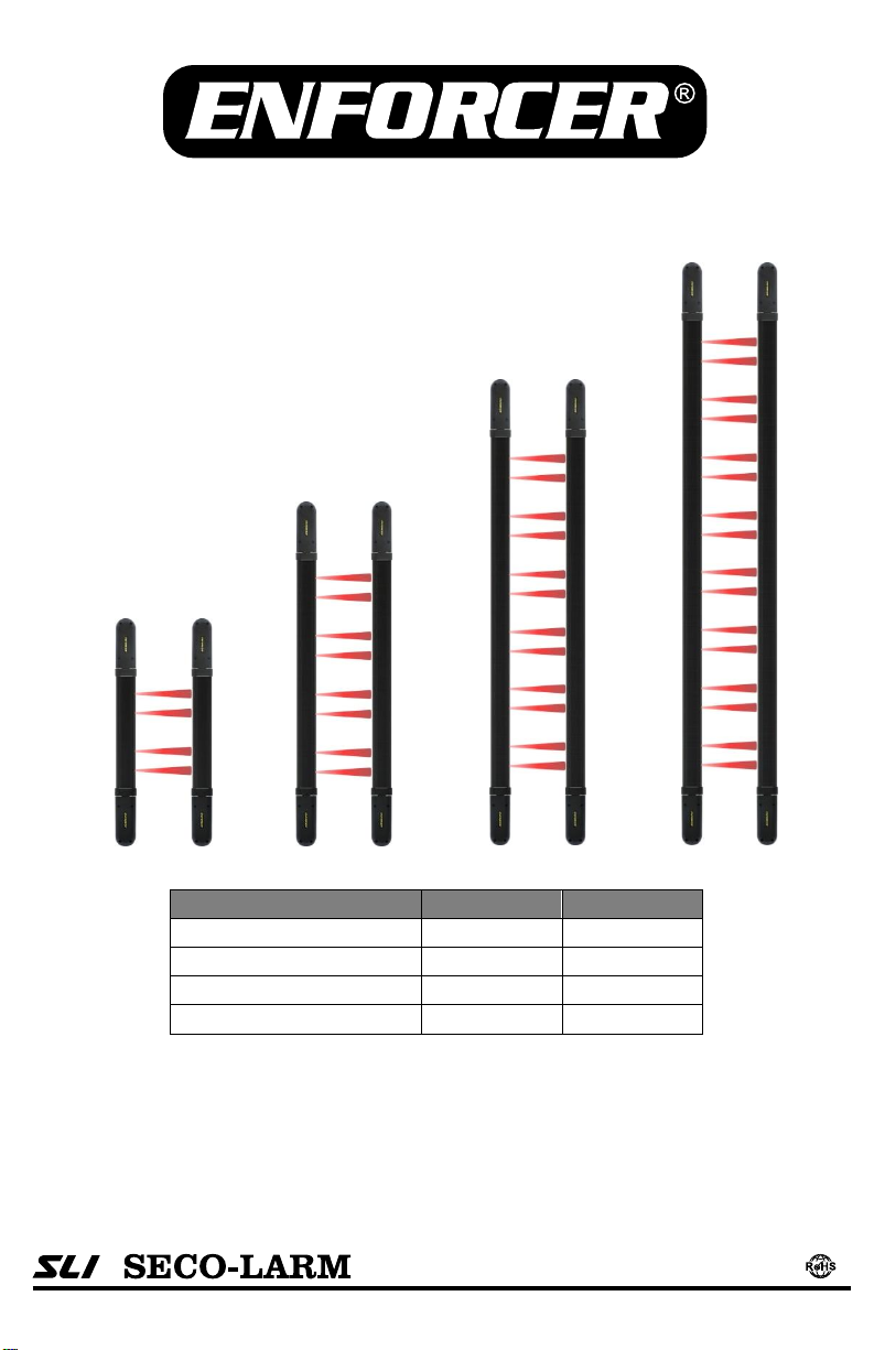
Long-Range Barrier Sensors
Manual
Model
# of Beams
Length
E-9626-2B190Q
2 pairs
26” (66cm)
E-9643-4B190Q
4 pairs
43” (109cm)
E-9661-6B190Q
6 pairs
61” (155cm)
E-9679-8B190Q
8 pairs
79” (201cm)
4 Different programmable frequencies
Range: Up to 190ft (60m) outdoor,
380ft (120m) indoor
End caps swivel for easy installation
Built-in heater for cold weather
operation
Note: Model numbers that end with “Q” or that have a round green “Q” sticker signify RoHS -compliant products.
Built-in tamper switches
Programmable trigger options
Form C relay output
Weatherproof IP65
AGC circuits ensure operation in rain,
fog, and low-temperature conditions
Page 2

ENFORCER Long-Range Barrier Sensors
2
SECO-LARM U.S.A., Inc.
Table of Contents:
Introduction:
ENFORCER Long-Range Barrier Sensors are ideal for protecting indoor or outdoor areas
separated by long distances. They feature reliable photobeam technology with a choice of
four programmable beam frequencies that provide superior perimeter protection by
eliminating crosstalk and interference when multiple units are used. False alarms caused
by animals, falling leaves, poor weather, or other sources are minimized by programming
the alarm output trigger operation.
ENFORCER Long-Range Barrier Sensors work in even the most extreme conditions. A
built-in heater automatically turns on and off depending on the outside temperature. An
environmental control system senses a slow degradation in beam strength when weather
conditions worsen to help prevent false alarms.
Installation and alignment is quick and easy with the ENFORCER Long-Range Barrier
Sensors. They come with swiveling heads that allow them to be mounted along the same
wall or on opposite walls, as well as provide for easy alignment of the beams between the
transmitter and receiver.
Parts List:
Introduction ............................................ 2
Parts List ................................................ 2
Features ................................................. 3
Specifications ......................................... 3
Dimensions ............................................ 4
Swivel Housing ....................................... 4
Sample Applications ............................... 4
Overview – Inside the Sensor ................ 5
Installation – Choosing a Location ......... 6
Installation – Wall vs. Pole Mounting ...... 7
Connecting Multiple Units ...................... 7
Installation – Running the Wires ............ 8
Installation – Mounting .......................... 8
Installation – Connecting the Wires ....... 9
Aligning the Beams .............................. 10
Programming the Trigger Mode ........... 10
Programming the Barrier Sensor ......... 11
Triggering the Barrier Sensor ............... 11
Troubleshooting ................................... 12
1 x Transmitter
1 x Receiver
1 x Manual
4 x Pole mount brackets
8 x Machine screws 4x6mm (for pole mount brackets)
8 x Machine screws 4x25mm (for pole mount brackets)
12 x Screws 6x20mm (for wall mount use)
12 x Plastic anchors (for wall mount use)
Page 3

ENFORCER Long-Range Barrier Sensors
SECO-LARM U.S.A., Inc.
3
Features:
Specifications:
Model
E-9626-2B190Q
E-9643-4B190Q
E-9661-6B190Q
E-9679-8B190Q
Number of beams
2 pairs
4 pairs
6 pairs
8 pairs
Max. range (outdoor)
190’ (60m)
Max. range (indoor)
380’ (120m)
Tx standby & active current,
heater off (+/-25%@12VDC)
56mA
84mA
100mA
109mA
Rx standby current (buzzer
off),heater off (+/-25%@12VDC)
66mA
80mA
95mA
108mA
Rx trigger current (buzzer on)
heater off (+/-25%@12VDC)
66mA
80mA
95mA
108mA
Buzzer active current (Rx only)
20mA@12VDC
Heater active current (Rx+Tx)
160mA@12VDC
Input voltage
12~24 VDC
Response time (receiver)
150/300/450/600 ms (DIP switch programmable)
Detection methods
Triggers as programmed when any 2 adjacent pair of beams are broken, or any
single pair of beams is broken for over 2 sec. (programmable by JP2)
Selectable beam frequencies
4 Different frequencies (DIP switch programmable)
Alarm output
NO/NC/COM, relay output, active for 1 sec. when triggered
Tamper output (Tx & Rx)
1A@120VAC / 1A@24VDC
Alignment LED (Rx only)
Red LED, ON – beam is broken / OFF – aligned
Alignment angle
Horizontal +/-90O
Operating temperature
-45OC~55OC (-49OF~131OF)
Humidity
95%
Ingress protection
IP65
Case
Aluminum housing / PC anti-UV cover / ABS end caps
Dimensions
See page 4, Dimensions for more details
Weight (Tx & Rx) with brackets
5.5lb (2.5kg)
7.7lb (3.5kg)
12.1lb (5.5kg)
14.3lb (6.5kg)
For indoor or outdoor perimeter security
Long sensor range up to 190ft (60m)
outdoors, 380ft (120m) indoors
Install on windows, doorways, skylights,
fence tops, and any place where space
is limited
End caps swivel so sensor can be
mounted on a single wall or on opposite
walls with no L-bracket needed
Programmable immediate trigger on
simultaneous breaking of beams, or trigger
after a single pair of beams is broken for at
least 2 seconds
Heater for use in cold weather operation
Heater activates at 41°F (5°C)
Terminal block wiring
Slim design: 2
1
/4” x 17/8” (55 x 49 mm)
Rugged aluminum construction
Built-in tamper switches, one on either end,
trigger the alarm if end cap is removed
No synchronizing wires required to align the
beams
Form C relay output
LED and buzzer alignment indicators
AGC (Auto Gain Control) circuits regulate
beam signals in order to compensate for
and ensure operation in rain, fog, and lowtemperature conditions
Programmable for 4 different frequencies to
reduce interference between
multiple units
Page 4
ENFORCER Long-Range Barrier Sensors
4
SECO-LARM U.S.A., Inc.
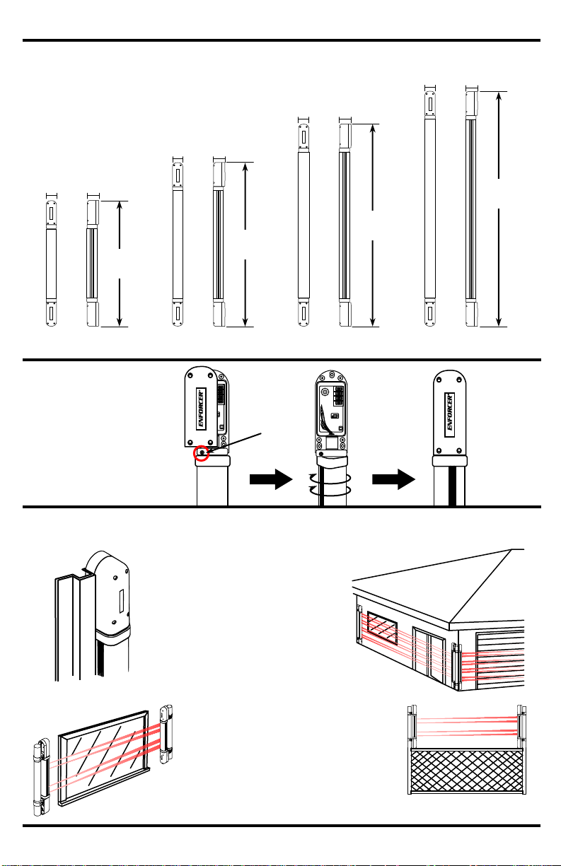
Dimensions:
21/4”
(55mm)
17/8”
(49mm)
21/4”
(55mm)
17/8”
(49mm)
21/4”
(55mm)
17/8”
(49mm)
21/4”
(55mm)
17/8”
(49mm)
26”
(66cm)
43”
(109cm)
61”
(155cm)
79”
(201cm)
E-9626-2B190Q
E-9643-4B190Q
E-9661-6B190Q
E-9679-8B190Q
Swivel Housing:
Each sensor is built
with a swivel housing
for flexible installations
and simple alignment.
To use, twist the
beams up to 90.
Sample Applications:
Typical
door/window
frame
Windows
Fence tops
Garages,
gates, and
walls
1. Remove cap
2. Loosen
swivel head
screw
3. Turn sensor
to desired
position
4. Tighten screw
and replace
the end cap
Page 5
ENFORCER Long-Range Barrier Sensors
SECO-LARM U.S.A., Inc.
5
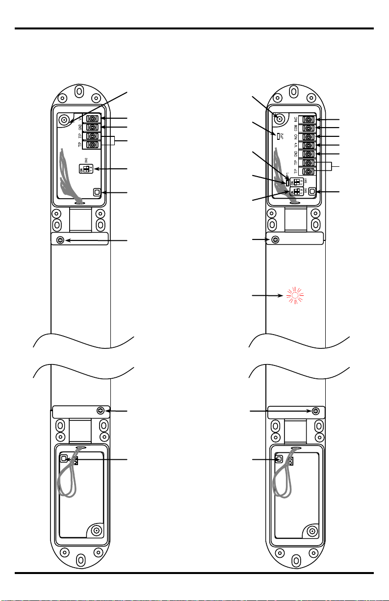
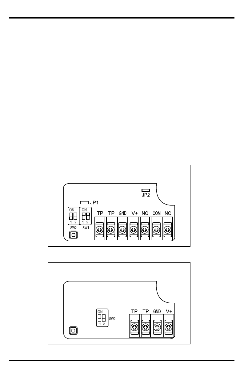
Overview – Inside the Sensor:
Transmitter
Receiver
Power
Ground
Tamper output
Channel selection
switch (SW2)
Tamper switch
Rubber wire
hole
Tamper switch
Rubber wire
hole
Beam alignment
buzzer jumper (JP1)
Response time
switch (SW1)
Channel selection
switch (SW2)
Tamper switch
Power
Ground
Tamper
output
Tamper
switch
Beam trigger program
jumper (JP2)
Swivel screw
Swivel screw
Swivel screw
Swivel screw
Red alignment/trigger
LED
COM
N.O.
N.C.
Page 6
ENFORCER Long-Range Barrier Sensors
6
SECO-LARM U.S.A., Inc.
Installation – Choosing a Location:
When used outdoors, place the Long-Range Barrier Sensor under a roof or
shelter. This will reduce the chance of false alarms caused by rain or snow.
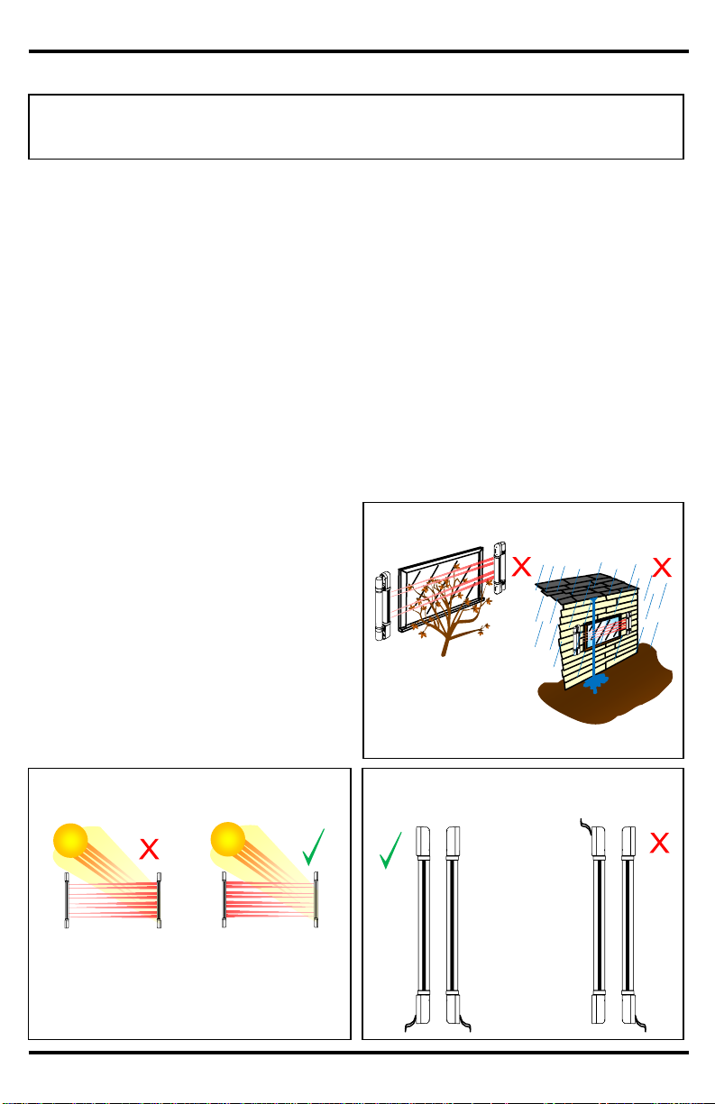
To prevent erratic operation and/or false alarms:
Do not mount near trees, bushes or
other leafy vegetation. Wind could
cause leaves or similar objects to fly or
wave into the beams (see Fig. 1).
Do not mount where water might run
off the roof and break the beam
(see Fig. 1).
Do not mount where the units could be
splashed by water or mud.
Do not let sunlight or any direct beam
of light shine directly on the sensor. If
unavoidable, mount in a way that the
transmitter – not the receiver – faces
the sun (see Fig. 2).
Mount the sensor so that the wires are
placed at the bottom. If the wires must
be placed on top, seal the opening
with silicone.
Do not mount in such a way that the
terminal block of one unit is at the top
and the other is at the bottom
(see Fig. 3).
Do not mount where animals or other
objects could accidentally break the
beams.
Do not mount near reflective surfaces,
as this could prevent the sensor from
working properly.
Do not mount where the unit could be
suddenly exposed to a bright light, such
as a floodlight or a passing
automobile’s headlight.
IMPORTANT: Do not connect to power until the sensor has been completely installed
and the installation has been double-checked.
Fig. 1 – Beware natural interference
Tree or shrub leaves
passing through beams
Rain running directly off
roof through beams
Fig. 2 – Orientation to the sun
Do not let sunlight or any direct beam of light shine
directly on the sensor. If unavoidable, mount in a
way that the transmitter – not the receiver – faces
the sun.
Tx
Rx
Rx
Tx
Fig. 3 – Orientation of the terminal
blocks
Mount so that the
terminal blocks of
both units are at the
top or both are at
the bottom. Do not
mount in such a
way that the
terminal block of
one unit is at the top
and the other is at
the bottom.
Page 7
ENFORCER Long-Range Barrier Sensors
SECO-LARM U.S.A., Inc.
7
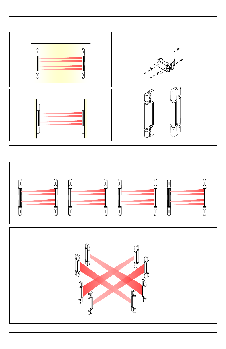
Connecting Multiple Units
CH 1 (TX)
CH 2 (RX)
CH 3 (RX)
CH 4 (TX)
CH 2 (TX)
CH 1 (RX)
CH 4 (RX)
CH 3 (TX)
Installation – Wall vs. Pole Mounting
Fig. 6 – Pole mounting
Fig. 4 – Wall mounting – Same wall
Fig. 5 – Wall mounting – Facing walls
Fig. 7 – Linear protection
CH1
CH1
TX
RX
CH3
CH3
TX
RX
CH2
CH2
TX
RX
CH4
CH4
TX
RX
Fig. 8 – Perimeter protection
(Pole-mount
brackets
included)
Machine screw
(4x6 mm)
Machine screw
(4x25 mm)
Page 8

ENFORCER Long-Range Barrier Sensors
8
SECO-LARM U.S.A., Inc.
Installation – Mounting
1. Find a suitable location.
a. The transmitter and receiver can be mounted at any angle as long as they are
parallel to each other and directly facing each other, and as long as the wires come
out of the same ends of both units (see Fig. 3).
b. If using multiple curtain sensors, be sure to set each for a different frequency
(see pg. 11).
c. The transmitter and receiver must not be separated by more than 190ft (60m)
outdoors or 380ft (120m) indoors.
2. Mount the transmitter and the receiver in such a way that surface-mounted wires do not
come out from above the units. This is to prevent water from entering via the wire holes.
If this is unavoidable, use silicone to completely cover the area where the wires come
out the holes to prevent water from entering
3. Once a suitable mounting location has been
found, remove the covers of the end caps
and locate the three mounting holes (see
Fig. 10). Using these holes as a template,
mark their location on the wall with a pencil.
4. Connect the wires (see pg. 9) before
permanently mounting the units to the wall.
Installation – Running the Wires
1. Run six wires (1 x power, 1 x ground, 2 x alarm signal, and 2 x tamper switch) from the
alarm control panel to the receiver of the sensor. Shielded cable is strongly suggested.
2. Run four wires (1 x power, 1 x ground, and 2 x tamper switch) from the alarm control
panel to the transmitter of the sensor. Shielded cable is strongly suggested.
Note: It may be more convenient to connect the transmitter’s power and tamper wires to
the receiver’s power and tamper wires.
3. If burying the wires is required, make sure to run them through electrical conduit.
Shielded cable is strongly suggested.
4. If the wires are run along the wall, the use of armored cable is strongly suggested.
Voltage
Gauge
Max. length
12VDC
AWG 22
1,800ft (550m)
12VDC
AWG 20
2,600ft (800m)
24VDC
AWG 22
2,600ft (800m)
24VDC
AWG 20
3,900ft (1,200m)
Fig. 9 – Maximum wire lengths
Fig. 10 – Mounting
Page 9
ENFORCER Long-Range Barrier Sensors
SECO-LARM U.S.A., Inc.
9
Installation – Connecting the Wires
1. Unscrew and pull the end cap off the side of the receiver with the terminal block
(see Fig. 11).
2. Run the wires through the rubber wire hole in the top corner of the back of the end cap.
3. Program the receiver (see pg. 11).
4. Replace the end cap. NOTE: End cap must be off when aligning the sensor.
5. Use a screwdriver to tighten the screws holding the end cap in place.
Receiver
1. Unscrew and pull the end cap off the side of the transmitter with the terminal block
(see Fig. 12).
2. Run the wires through the rubber wire hole in the top corner of the back of the end cap.
3. Program the transmitter.
4. Replace the end cap. NOTE: End cap must be off when aligning the sensor.
5. Use a screwdriver to tighten the screws holding the end cap in place.
Transmitter
Fig. 11 – Receiver circuit board
Fig. 12 – Transmitter circuit board
Page 10

ENFORCER Long-Range Barrier Sensors
10
SECO-LARM U.S.A., Inc.
Aligning the Beams
1. To align the beams, loosen the swivel screw and adjust the beams to face each other.
Connect the power to the receiver and transmitter. If the beams are not aligned, the red
LED on the receiver will light ON (see Fig. 13).
2. For audible confirmation in addition to the LED, make sure jumper JP1 is plugged in on
the receiver’s circuit board. If the beams are not aligned, the receiver’s buzzer will
sound. To disable this feature, remove JP1 (see Fig. 14).
3. Once the beams are aligned, the red LED will turn off and the buzzer will not sound.
Programming the Trigger Mode
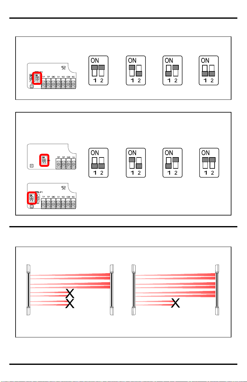
1. The default detection method is when any 2 adjacent pair of beams is broken, or when
any single pair of beams are broken more than 2 seconds (see Fig.19).
2. The latter (any single pair of beams broken) detection function can be disabled when
the JP2 jumper is removed.
Fig. 13 – Aligning the beams
Fig. 14 – Jumper position (JP1)
Alignment buzzer
OFF
Alignment buzzer
ON
Fig. 15 – Programming buzzer ON/OFF
(JP1) and detection mode (JP2).
Fig. 16 – Jumper position (JP2)
Detection mode
OFF
Detection mode
ON
Tx
Tx
Rx
Rx
Page 11
ENFORCER Long-Range Barrier Sensors
SECO-LARM U.S.A., Inc.
11
Any two adjacent pair tripped
Response time: programmable
150/300/450/600ms
Programming the Barrier Sensor
Fig. 17 – Programming the response time (SW1)
300ms
450ms
600ms
150ms
Receiver circuit board
Triggering the Barrier Sensor
Fig. 19 – Ways to trigger the sensor
Any single pair tripped
Response time: 2 seconds
(Programmable, see page 10)
Fig. 18 – Programming the sensor beam channel frequency (SW2)
Receiver circuit board
CH2
CH3
CH4
CH1
Transmitter circuit board
Page 12

ENFORCER Long-Range Barrier Sensors
12
SECO-LARM U.S.A., Inc.
MiE-96xx-xB190QXX_1107.docx
PITSW3
WARRANTY: This SECO-LARM product is warranted against defects in material and workmanship while used in normal service for a
period of one (1) year from the date of sale to the original customer. SECO-LARM’s obligation is limited to the repair or replacement of
any defective part if the unit is returned, transportation prepaid, to SECO-LARM.
This Warranty is void if damage is caused by or attributed to acts of God, physical or electrical misuse or abuse, neglect, repair or
alteration, improper or abnormal usage, or faulty installation, or if for any other reason SECO-LARM determines that such equipment is
not operating properly as a result of causes other than defects in material and workmanship.
The sole obligation of SECO-LARM and the purchaser’s exclusive remedy, shall be limited to replacement or repair only, at
SECO-LARM’s option. In no event shall SECO-LARM be liable for any special, collateral, incidental, or consequential personal or
property damages of any kind to the purchaser or anyone else.
NOTICE
The information and specifications printed in this manual are current at the time of publication. However, the SECO-LARM policy is
one of continual development and improvement. For this reason, SECO-LARM reserves the right to change specifications without
notice. SECO-LARM is also not responsible for misprints or typographical errors.
Copyright © 2012 SECO-LARM U.S.A., Inc. All rights reserved. This material may not be reproduced or copied, in whole or in part,
without the written permission of SECO-LARM.
SECO-LARM U.S.A., Inc.
16842 Millikan Avenue, Irvine, CA 92606
Tel: 800-662-0800 / 949-261-2999
Website: www.seco-larm.com
E-mail: sales@seco-larm.com
Receiver LED never turns ON and the buzzer never
sounds
Test the power and ground wire with a voltage meter to
ensure power is connected and is of the correct voltage
Buzzer does not sound if the sensor is triggered
If jumper J1 is plugged in, this indicates that the beams are
not aligned
If jumper J1 is not plugged in, buzzer should never sound
Receiver LED is ON and the buzzer sounds all the
time
Realign the transmitter and receiver
Does not trigger when beam is broken
Remount the curtain sensor, or repaint the surface to cut
down on reflection
Lower the response time (SW1)
Receiver continuously triggers the alarm
Realign the transmitter and receiver
Check that the tamper switch and the cover for the tamper
switch are mounted correctly
False alarm
Reinstall so that one sensor does not interfere with another
sensor
Cut back on leafy vegetation
Do not mount under the edge of the roof
Mount under a roof or shelter
Troubleshooting:
Also Available from SECO-LARM:
Curtain Beam
Sensors
Dual Beam
Sensors
Retro-Reflective
Beam Sensors
Quad Beam
Sensors
 Loading...