

Page 1
®
ENFORCER
Sensor
Single
Photobeam
Sensor
E-961-S90W
Range: 90ft. (30m)
INSTALLATION MANUAL
Features: Typical Applications:
••
•
Infrared single photobeam sensor.
••
••
•
Range: Up to 90 feet (30m)
••
••
•
IP-66 weatherproof protection.
••
••
•
For indoor and outdoor use.
••
••
•
10~24V AC/DC input voltage.
••
••
•
Horizontal and vertical adjustment for easy
••
alignment.
••
•
N.C./N.O./COM relay outputs.
••
••
•
Adjustable low or high sensor beam brightness.
••
•
Safety sensor for garage doors or outdoor gates.
•
Overhead door security sensor.
•
Industrial automation -- detect small objects on
a manufacturing line.
•
Entry detection for store fronts.
•
Assist in measuring parking distance.
•
Alarm sensor.
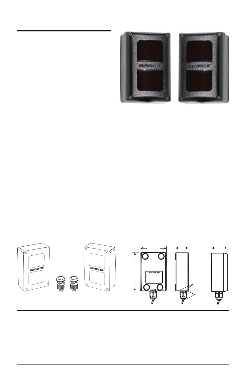
Fig. 1 - Included
Transmitter ReceiverCable Glands
Caution:
•
This sensor was not designed to prevent bodily
injury or loss of life.
•
This sensor was not designed for use in
environments where there is the possibility of
explosive gasses present.
Dimensions:
23/8"
(59mm)
"
8
/
3
3
(86.5mm)
•
Use of this sensor in certain security
applications may be regulated by local laws or
codes. SECO-LARM is not responsible for
compliance with such laws or codes.
11/8"
(29mm)
5
/8"
(16mm)
13
/16"
(21mm)
17/16"
(40mm)
Page 2
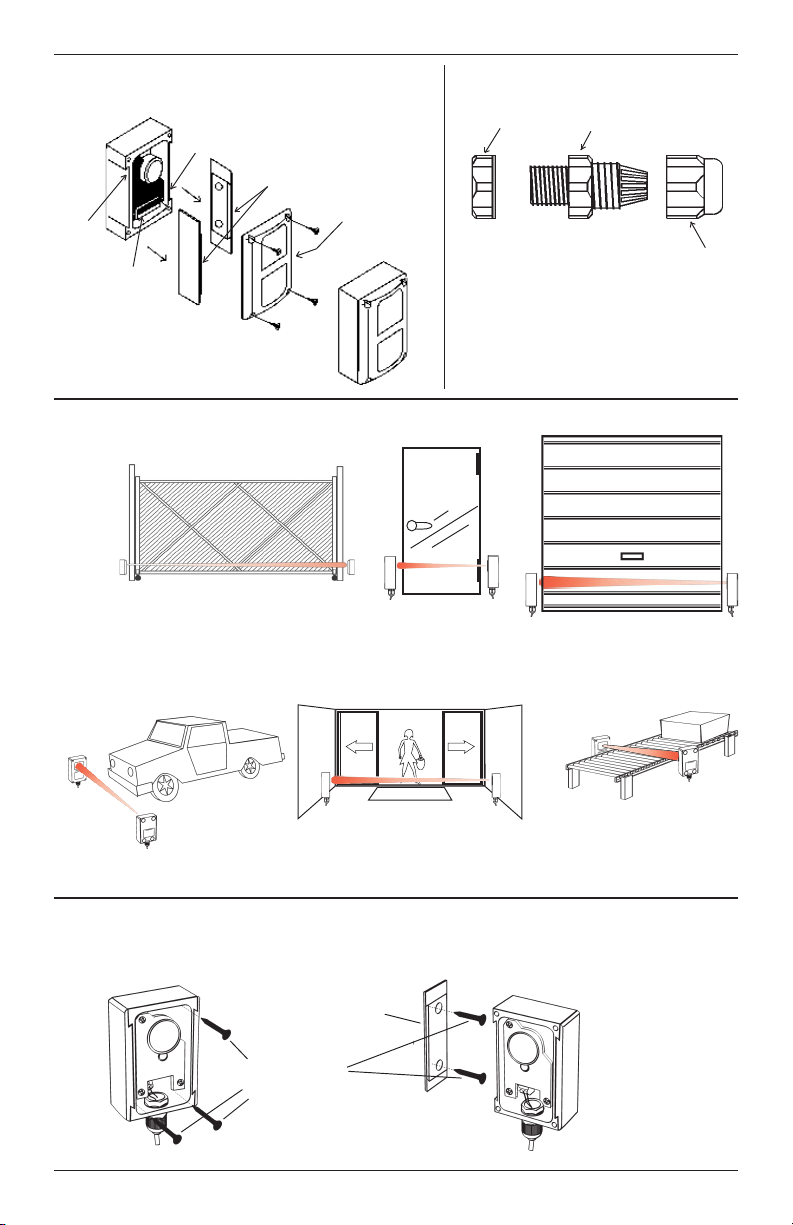
Fig. 2 - Sensor
Horizontal
Adjustment
Screw
Mounting
Brackets
Fig. 3 - Cable Gland
Lock Nut
Body
Vertical
Adjustment
Screw
Terminal
Block
Fig. 4 - Sample Installations
Gates
Vehicle detection
Lens Cover
entrance
Store front door
m
c
o
e
l
Main
door
W
e
Nut
Garage
door
Factory assembly line
Fig. 5 - Mounting
Flush Mount
Mounting Screws
(not included). Be
sure to use flat-
head, flush
mounting screws.
Side
Bracket
Perpendicular Mount
2
Attach bracket
to wall. Then
slide sensor
onto bracket.
Page 3

Fig. 6 - Wiring and Adjusting
Vertical
Adjustment
Screw
Lens
Green
LED
Horizontal
Adjustment
C
Screw
Tx Power Setting
Wiring Block
Cable Gland
Transmitter Receiver
Red
LED
+
-
NO NC COM
Transmitter
10-24VAC/VDC,
{
Polarity not important
Receiver
Relay Output - COM
Relay Output - N.C.
Relay Output - N.O.
10-24VAC/VDC,
{
Polarity not important
Installation and Alignment:
LED functions:
GREEN LED – When ON, indicates power is present.
RED LED – When ON, indicates the sensor is
aligned properly.
When OFF, indicates the sensor is not
aligned properly, or the beam has
been interrupted.
Installation:
1. Install one cable gland in the bottom of the
transmitter, and one in the bottom of the receiver:
a. Remove the lens cover.
b. Carve out the holes in the transmitter and
receiver with a sharp tool.
c. Take the lock nut off the cable gland (see fig. 3),
insert the cable gland into the hole from the
bottom, and tighten with the lock nut.
2. Wire the unit – Run the wires to where the sensor is
to be mounted. Keep wires hidden where possible,
and expose them only at the very end where needed
to connect to the transmitter and receiver. (see fig.6)
3. Decide where to mount:
a. The transmitter and receiver should be facing
each other.
b. The units should not interfere with normal
movement around the protected area.
4. Initial test – Temporarily hold the transmitter and
receiver to the wall where they are to be mounted and
power up the units to test alignment before
permanent mounting. (See Power and Alignment
below.)
5. Mount the transmitter/receiver (flush mount) (fig. 5)
– Mount flush to the wall with three mounting
screws (not included).
6. Mount the transmitter/receiver (perpendicular mount)
(fig. 5):
a. Depending on how mounted, remove one of the
two side brackets.
b. Screw the side bracket into the wall using two
mounting screws (not included).
c. Slide the transmitter or receiver onto the side
bracket.
Power and Alignment
1. Power up the transmitter and receiver. The green LED
on the transmitter should turn ON to indicate power is
present. The red LED on the receiver should turn ON
to indicate the two are aligned properly.
2. Alignment – If the receiver is connected to power, and
if the red LED does not turn on while the green LED is
on, the transmitter and receiver are not aligned.
Loosen or tighten the horizontal and vertical
adjustment screws on the transmitter and/or receiver
until the red LED turns on, indicating alignment.
(Fig. 6.)
NOTE – If two or more E-961-S90W pairs are
installed within close proximity of each other, adjust
the sensor beam brightness to “low” by cutting the
wire loop on the transmitter circuit board just above
the “TX” marking.
Testing:
1. Do a walk-through test. Walk between the transmitter
and receiver. This should break the beam, turn the
red LED off, and trigger the alarm panel or warning
device.
2. Replace the lens covers on the transmitter and
receiver. Test again one last time.
3
Page 4

Specifications:
Technology:
Sensing range
Input voltage
Response time
Emitting element
Operation indicator
Current consumption
Relay
Tx power adjust.
Sensing angle adjust
Illumination
Noise resistance
Surge resistance
Vibration resistance
Material
Operating temp.
Weather-Proof
Approvals
Through-beam photoelectric sensor
90 feet (30 meters)
10~24 VAC/VDC
100ms
Infrared LED
Red LED on for standby (TX) / Green LED show power (RX)
33.5mA (TX), 27.5mA (beam aligned) / 13mA (beam broken) (RX)
1A, 120VAC, N.O./N.C./COM
Low vs. high
Horizontal +/-5°, vertical +/-5
°
Lamplight <10,000 lux, sunlight <30,000 lux
1,500 Vp-P/1us
2KV/1us
10~55 Hz/1.5mm, 2 hours in X.Y.Z. phase
Case — nylon, lens — polycarbonate
-13°~140°F (-25°~60°C)
IP-66 standard
CE standard
Troubleshooting:
Trouble Remedy(s)Possible Origin(s)
Sensor does not detect the object. 1) Sensor sensitivity is not properly set.
2) Object may have a reflective surface
which confuses sensor.
Red LED does not turn on. 1) Dirty sensor and/or reflector.
Red LED lights when object is
detected, but no output.
2) Reflector and/or sensor is misaligned.
No continuity between sensor and alarm
device.
Change the angle of the sensor or
readjust the sensitivity setting.
1) Clean the sensor and reflector with a
damp (not wet) cloth.
2) Adjust the reflector and/or sensor for
proper alignment.
Check cable from sensor to alarm
device. Test sensor.
WARRANTY:
while used in normal service for a period of one (1) year from the date of sale to the original customer. Our obligation is
limited to the repair or replacement of any defective part if the unit is returned, transportation pre-paid, to SECO-LARM.
ENFORCER Photobeam Sensors are warranted against defects in material and workmanship
NOTICE
The information and specifications printed in this manual are current at the time of publication. However, the SECO-LARM
policy is one of continual development and improvement. For this reason, SECO-LARM reserves the right to change
specifications without notice. SECO-LARM is also not responsible for misprints or typographical errors.
Copyright © 2004 SECO-LARM U.S.A., Inc. All rights reserved. This material may not be reproduced or copied, in whole
or in part, without the written permission of SECO-LARM.
SECO-LARMSECO-LARM
SECO-LARM
SECO-LARMSECO-LARM
16842 Millikan Avenue, Irvine, CA 92606
Tel: 800-662-0800 / 949-261-2999 Fax: 949-261-7326
®
U.S.A., Inc. U.S.A., Inc.
U.S.A., Inc.
U.S.A., Inc. U.S.A., Inc.
Website: www.seco-larm.com
E-mail: sales
@
seco-larm.com
®
PITSW3
MiE961S90W.PMD
 Loading...