

Page 1
E024S
Page 2
INDEX
0 BOX LAYOUT .....................................................................................................................................2
1 WARNINGS .......................................................................................................................................3
2 LAYOUT AND CONNECTION
3 TECHNICAL SPECIFICATIONS
3.1 DESCRIPTION OF COMPONENTS ........................................................................................................ 4
3.2 DESCRIPTION OF TERMINAL-BOARDS .................................................................................................
4 PROGRAMMING THE LOGIC .............................................................................................................4
5 PROGRAMMING THE SPEED ..............................................................................................................4
6. START-UP ...........................................................................................................................................5
6.1 LEDS CHECK...................................................................................................................................... 5
6.2 PROGRAMMING THE DIPS-SWITCH .....................................................................................................
6.3 TIME - SETUP LEARNING .....................................................................................................................
6.3.1 AUTOMATIC SET-UP ................................................................................................................................................5
6.3.2 MANUAL SET-UP .....................................................................................................................................................
6.3.3 PROGRAMMING OF THE LOGIC
6.3.4 SECOND LEVEL PROGRAMMING - ADVANCED FUNCTIONS ....................................................................................6
7 INSTALLATION OF BUS ACCESSORIES ................................................................................................7
7.1 ADDRESSING THE BUS PHOTOCELLS .................................................................................................. 7
7.2 MEMORY STORAGE OF BUS ACCESSORIES .......................................................................................
8 MEMORY STORING THE RADIO CODE ...............................................................................................8
8.1 MEMORY STORAGE OF DS RADIO CONTROLS ................................................................................... 8
8.2 MEMORY STORAGE OF SLH RADIO CONTROLS
8.3 MEMORY STORAGE OF LC RADIO CONTROLS ...................................................................................
8.3.1 REMOTE MEMORY STORAGE OF LC RADIO CONTROLS ..................................................9
8.4 RADIO CONTROLS DELETION PROCEDURE ........................................................................................ 9
S ............................................................................................................3
...........................................................................................................4
............................................................................................................................6
.................................................................................. 8
4
5
5
5
ENGLISH
8
9
9 CONNECTION OF BUFFER BATTERIES (OPTIONAL) ..............................................................................9
10 AUTOMATED SYSTEM TEST .................................................................................................................
11
S700H ADDRESSING BUS ENCODER ...............................................................................................
12 LOGIC TABLES .................................................................................................................................
10
10
CE DECLARATION OF CONFORMITY
Manufacturer: FAAC S.p.A.
Address: Via Benini, 1 - 40069 Zola Predosa BOLOGNA - ITALY
Declares that: Control board mod. E024S,
• conforms to the essential safety requirements of the following EEC directives:
2006/95/EC Low Voltage Directive
2004/108/EC Electromagnetic Compatibility Directive
Additional information:
This product underwent a test in a typical, uniform configuration.
(all products made by FAAC S.p.A)
Bologna 01-03-2009. The Managing Director
A. Marcellan
9
WARNINGS
• Important! For the safety of people, it is important that all the instructions be carefully observed.
• Incorrect installation or incorrect use of the product could cause serious harm to people.
• Carefully read the instructions before beginning to install the product and keep them for future
reference.
• The symbol indicates notes that are important for the safety of persons and for the good condition
of the automated system.
• The symbol draws your attention to the notes on the characteristics and operation of the product.
1
Page 3
ELECTRICAL BOX E024S
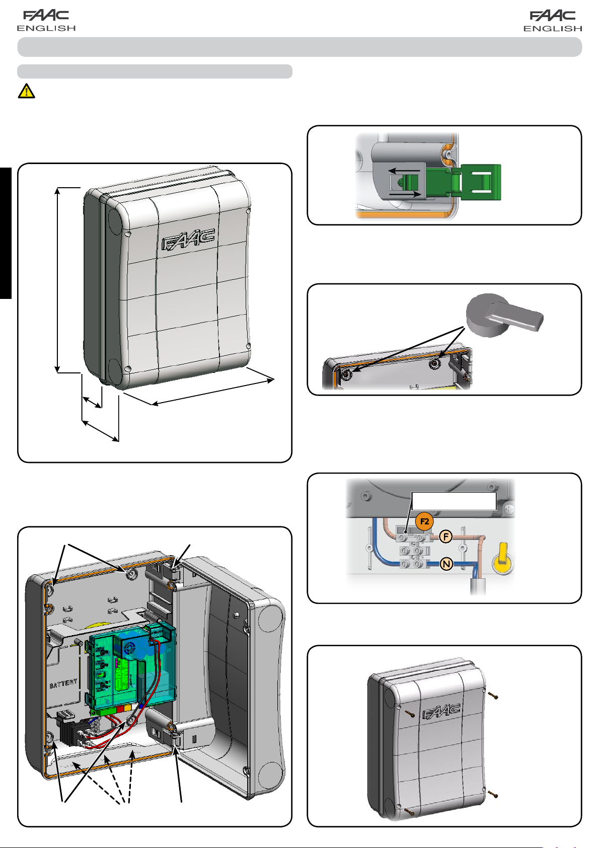
0 BOX LAYOUT
THE BOX CONTAINS THE E024S ELECTRONIC UNIT AND
THE DEVICES TO POWER IT. IT MUST THEREFORE BE HANDLED WITH CARE DURING ALL INSTALLATION STAGES, TO
AVOID DAMAGING ITS COMPONENTS.
The dimensions of the box are shown in Fig.A:
ENGLISH
306
The lid hinges can be moved upward to allow opening the box
housing (Fig. C); they can also be removed and re-positioned
in order to enable the lid to open to the right or left.
Fig. C
When you have secured the box in the selected position, cover
the securing holes (ref.
plugs as shown in Fig.D.
Fig.B) and the screws with the supplied
64
130
Dimensions in mm
225
Fig. A
Fig. B shows the four 5 mm diam. holes for securing the box
(ref.) to the wall, the three fittings M16/M20/M25 for installing
the cable grippers (ref.) and the two lid hinges (ref.).
Fig. D
After you have finished the operations to connect the control
board with the various parts of the automated system, close
the box, positioning the lid in its seat with seal.
Connect the supply as shown in Fig. E.
230V -> 2,5A - 250V
115V -> 4A - 120V
Fig. E
Next, tighten the four supplied screws to guarantee the degree
of protection against external agents (Fig.F).
Fig. B
Fig. F
2
Page 4
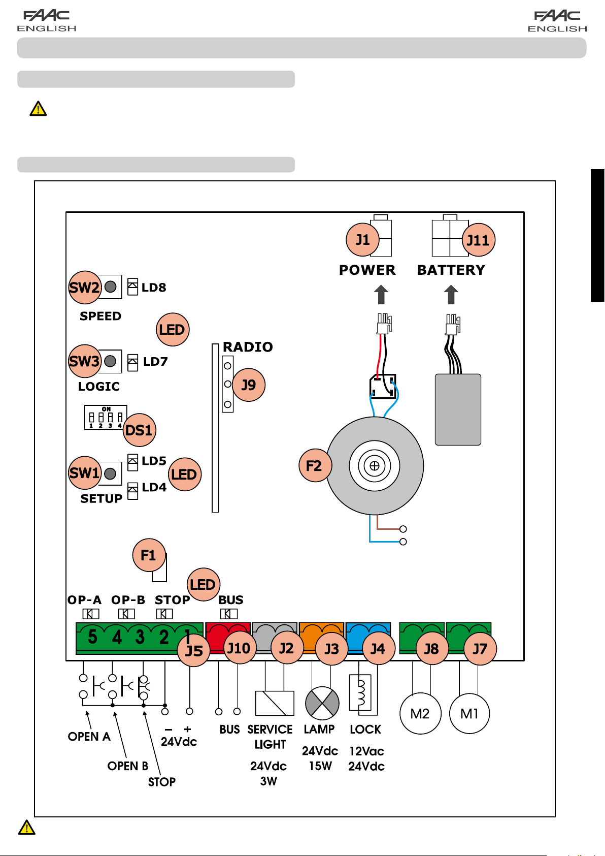
Fig. 1Fig. 1
CONTROL UNIT E024S
1 WARNINGS
Before attempting any work on the control unit (connections, maintenance), always turn off power.
- Install, upstream of the system, a differential thermal breaker with adequate tripping threshold,
- Always separate power cables from control and safety cables (push-button, receiver, photocells, etc.).
- To avoid any electrical disturbance, use separate sheaths or a screened cable (with the screen earthed).
2 LAYOUT AND CONNECTIONS
ENGLISH
(TOTAL OPENING)
(PARTIAL OPENING)
230 VAC 50HZ
or
115 Vac 60Hz *
1
*1 THE POWER SUPPLY IS RELATED TO THE E024S PURCHASED VERSION.
3
Page 5
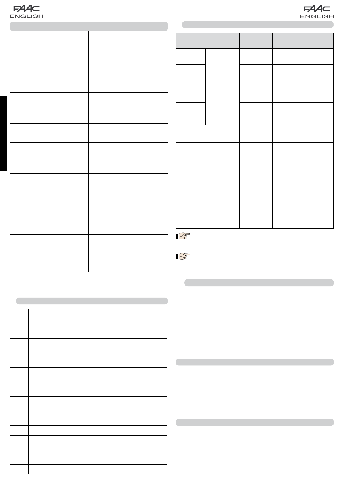
3 TECHNICAL SPECIFICATIONS
Power supply voltage
Absorbed power
Motor max. load
Accessories max. current
(+24V)
BUS Accessories max.current
Operating ambient temperature
Fuses
Function logics
Work time (time-out)
ENGLISH
Pause time
Terminal board inputs
Connector inputs
Terminal board outputs
Programmable functions
Learning functions
Integrated radio channels
type
2
*
*
2
230Vac (+6% -10%) - 50Hz
115Vac (+6% -10%) - 60Hz
F1 = self-resetting;
F2 = T2A-250V
A, E, AP, EP,A1,B,C
5 minute (fixed)
Varies according to learning
Open A, Open B, Stop, BUS
Power supply, battery
module XF 433 or XF 868
Motors, flashing lamp, power
supply to accessories,
electric lock, service light
contact (90 sec fixed)
Logic (
Speed (High - Low)
leaf closing delay
DS, SLH (max 250 channels)
LC (max 250 channels -
or
4W
150W x 2
250 mA
400 mA
-20°C... +55°C
or T4A-120V
(max. 10 min.)
(I/O)
A, E, AP, EP,A1,B,C
Pause time,
3.2 DESCRIPTION OF TERMINAL-BOARDS
Terminal and/or
terminal-board
1
Description Device connected
+24V
Power supply for
accessories
2 GND Negative
Device with NC
3 STOP
J5
contact which causes
the automated
system to shut down
4 OPEN B
Device with N.O
contact (see chap.
5 OPEN A
J10
RED terminal
BUS
FUNCTION LOGICS)
Safety devices with
BUS technology
Service Light control
J2
GREY terminal
SERVICE
LIGHT
output (connect a
relay coil at 24Vdc100mA max)
J3
ORANGE terminal
J4
BLUE terminal
LAMP
LOCK
Flashing lamp 24Vdc
- 15W
Electric lock 12Vac or
24 Vdc (to be installed
on leaf 1)
J7 MOT1 Motor 1 (leaf 1)
),
J8 MOT2 Motor 2 (leaf 2)
Leaf 1 means the leaf which opens first during
the opening operation.
The service light control is active during the
entire gate opening or closing movement and
for the successive 90 seconds.
*2 The power supply and the fuse are related to the purchased
version.
3.1 DESCRIPTION OF COMPONENTS
J1 POWER SUPPLY connector
J2
SERVICE LIGHT command terminal-board
J3 FLASHING LAMP terminal-board
J4 ELECTRIC LOCK terminal-board
J5 COMMANDS terminal-board
J7 MOTOR 1 terminal-board
J8 MOTOR 2 terminal-board
J9 Rapid connection for XF MODULE
J10 BUS terminal-board
J11 BATTERY connector
SW1 SET UP push-button
SW2 SPEED push-button
SW3 LOGIC push-button
DS1 Programming Dip-switch
F1 Accessories protective fuse
F2 Fuses protecting transformers and motors
LED Signalling LEDs
3.3 ANTI-CRUSHING FUNCTION
The electronic anti-crushing function is obtained by controlling
the current consumption or the encoder of the motors connected to the E024S equipment.
If the gate detects an obstacle during the opening or closing
movement, the anti-crushing function activates and reverses
the sense of direction of the operator, thus increasing the safety
degree of the automated system.
4 PROGRAMMING OF THE LOGIC
Repeatedly press the SW3 LOGIC push-button to select one of
the 7 programming logics available.
The selected logic is signaled by the LD7 LED: the number of
blinkings corresponds to the number of the selected logic.
See paragraph 6.3.3.
5 PROGRAMMING THE SPEED
The function SPEED can be adjusted at any time by pressing
push-button SW2.
The selected speed is then displayed on LED LD8:
LED on = HIGH speed
LED off = LOW speed
4
Page 6

6 START-UP
6.1 LEDS CHECK
The following table shows that status of the LEDs in relation to
the status of the inputs (the closed at rest automated system
condition is shown in bold).
Check the status of the signalling LEDs as per table below:
6.3 TIME - SETUP LEARNING
Before any manoeuvre is executed, a SETUP
cycle must first be run.
If the motor type is changed with the DS3 and
DS4 dip-switches after the SETUP, a new SETUP
is requested.
Tab.1 – Operation of inputs status LEDs
LED ON (closed contact) OFF (open contact)
STOP Command disabled Command enabled
OPEN A Command enabled
OPEN B Command enabled
BUS See par. 7.2
Command disabled
Command disabled
6.2 PROGRAMMING THE DIPS-SWITCH
The settings of the DS1 dip-switch for programming the force
and the type of motor are shown in the following table.
Tab. 2 - DS1 programming
(default settings in bold)
DS1 DS2 DS3 DS4 Description
OFF OFF LOW FORCE
OFF ON MEDIUM - LOW FORCE
ON OFF MEDIUM - HIGH FORCE
ON ON HIGH FORCE
OFF OFF MOTOR 391
OFF ON MOTOR 418
ON
ON
(*) If DS3-DS4 are set to ON, during the setup
phase the EncS700 or EncS450 encoder automatically recognizes the S700H or S450H connected operator.
OFF MOTOR 413-415-390-770
ON HYDRAULIC MOTOR (*) S450H
/ S700H
When the board is powered up and a SETUP cycle has never
been executed, LEDs LD4 and LD5 begin to flash slowly to signal
that a SETUP cycle must be executed.
There are two possible types of SETUP: AUTOMATIC and
MANUAL
6.3.1 AUTOMATIC SETUP
To enter in Automatic setup, press the SETUP push-button until
the two LD4 and LD5 LEDs are permanently lit. Then release
the SETUP push-button.
During the Setup phase both LEDs blink.
The Setup phase is preceded by a preliminary phase,
6.2.1.
Then the leaves start moving, one at a time, from the closed
position.
1.
Once an opening stop or an "open" impulse is detected,
they reach the open position and the setup is ended.
Slow-downs can not be set.
The pause time is fixed at 30 s.
Once the SETUP procedure is started, switch
the motor supply cables if the leaves close
instead of opening.
With the AUTOMATIC SETUP, the slow-down
spaces, the closing leaf delays and the pause
time (30 s, with A logic) are defined during
the Setup phase. To change the opening/clos
ing leaf delay and the pause time, use the
second level menu.
ENGLISH
Before performing the Setup, select the opera-
tor connected to the E024S equipment with the
DS1(DS3-DS4) DIP switches.
6.2.1 PRELIMINARY PHASE OF AUTOMATIC OR MANUAL SETUP
The Automatic or Manual SETUP phase is preceded by an initialisation phase: by pressing the SETUP push-button for automatic
or manual setup, the leaves open, one at a time and from any
position, until an obstacle or an Open impulse is detected. Then
the leaves start closing, one at a time, until an obstacle or an
Open impulse is detected. Then the procedure described in
paragraph 6.3.1 or paragraph 6.3.2 starts.
At the end of a successful SETUP procedure the LEDs switch
off.
Otherwise, the procedure ends with the request of a new SETUP
signaled by blinking LEDs.
6.3.2 MANUAL SETUP
To enter in Manual setup, press the SETUP push-button until the
two LD4 and LD5 LEDs are permanently lit. Keep it pressed until
the automated system starts moving automatically.
During the Setup phase both LEDs blink.
The Setup phase is preceded by a preliminary phase,
6.2.1.
Then the leaves start moving, one at a time, from the closed
position with an "open" command or automatically.
1.
Open impulse ---> slowdown from leaf opening 1. If a
stop is detected, an opening stop search is set. If Open is
detected, a stop in the stored open position is set.
2.
Starting from leaf opening 2.
5
Page 7

3. Open impulse ---> slowdown from leaf opening 2. If a stop
is detected, an opening stop search is set. If Open is detected,
a stop in the stored open position is set.
4. From now until the next Open impulse, the pause time is
counted.
5. Open impulse ---> Pause time acquisition and start from
leaf closing 2.
6. Open impulse ---> Slowdown from leaf closing 2. If a stop
is detected, an closing stop search is set. If Open is detected,
a stop in closed position is set (only with absolute encoder
Enc450).
7. Starting from leaf closing 1.
8. Open impulse ---> slowdown from leaf closing 1. If a stop
is detected, an closing stop search is set. If Open is detected,
a stop in closed position is set (only with absolute encoder
ENGLISH
Enc450).
Once the SETUP procedure is started, switch the
motor supply cables if the leaves close instead
of opening.
With the MANUAL SETUP the slow-down spaces
and the leaf closing delays are set from the
board during the Setup phase. As an alternative, the leaf opening/closing delay and the
pause time can be changed in the second level
programming without repeating the Setup.
6.3.3 PROGRAMMING OF THE LOGIC
Repeatedly press the SW3 push-button to select one of the 7
programming logics available.
The selected logic is signaled by the LD7 LED.
The number of blinkings corresponds to the number of the selected
logic:
Logic A (Automatic)
SW3 pressed once - LD7 blinking once
Logic E (Semi-automatic)
SW3 pressed twice - LD7 blinking twice
Logic AP ("Stepped" automatic)
SW3 pressed three times - LD7 blinking three times
Logic EP ("Stepped" semi-automatic)
SW3 pressed four times - LD7 blinking four times
Logic A1 (Automatic 1)
SW3 pressed five times - LD7 blinking five times
Logic b (Semi-automatic “b”)
SW3 pressed six times - LD7 blinking six times
Logic C (Dead man)
SW3 pressed seven times - LD7 blinking seven times
6.3.4 SECOND LEVEL PROGRAMMING -
ADVANCED FUNCTIONS
To enter the second level menu, keep the SW2 SPEED pushbutton pressed for more the 2.5 seconds. The two SETUP LEDs
are permanently lit. In this mode, the SPEED push-button is used
to scroll the menus. The different menus are identified by the
number of blinkings.
The parameter value is set with the LOGIC push-button. The
menu is scrolled sequentially. Keep the SPEED push-button
pressed for 2.5 seconds to exit the second level menu.
Menu 1 Wind-proof facility 1 SW2 pressed once
LD8 blinking once
Wind-proof facility NO LD7 LED OFF
Wind-proof facility YES LD7 LED
Menu 2
LD8 blinking twice
Reverse Stroke NO LD7 LED OFF
Reverse Stroke YES LD7 LED
Menu 3
LD8 blinking three times
Soft-touch NO LD7 LED OFF
Soft-touch YES LD7 LED
Menu 4 Preliminary blinking SW2 pressed four times
LD8 blinking four times
Preliminary blinking NO LD7 LED OFF
Preliminary blinking YES LD7 LED ON
Menu 5
LD8 blinking five times
Leaf opening delay NO LD7 LED OFF
Leaf opening delay YES LD7 LED ON
Menu 6
LD8 blinking six times
Leaf closing delay -- LD7 LED OFF
Leaf closing delay, count LD7 LED ON
Menu 7 Pause time SW2 pressed seven times
LD8 blinking seven times
Pause time -- LD7 LED OFF
Pause time, count LD7 LED ON
Reverse Stroke SW2 pressed twice
Soft-touch SW2 pressed three times
ON
Leaf opening delay SW2 pressed five times
Leaf closing delay SW2 pressed six times
With menus 6 and 7, keep the LOGIC push-
button pressed until reaching the time to be set.
Th e t i m e c a n be s et b e t w e e n 0 a n d
4.25 minutes.
ON
ON
6
Page 8

6.3.5 RETURN TO DEFAULT SETTINGS
Restore the default settings as follows:
Keep the SETUP push-button pressed to switch the board
1.
ON.
The two SETUP LEDs are alternately lit ("level crossing"
2.
mode).
The board resets the parameters.
3.
Until the SETUP push-button is pressed, movements are
4.
inhibited.
When the SETUP push-button is released, the two LD4 and
5.
LD5 LEDs blink.
The default configuration is reset and the new Setup can
6.
be started.
Fig. 2
6.3.6 DEFAULT PARAMETERS
Here the default parameters:
- Logic: A
- Wind-proof facility: NO
- Reverse Stroke: NO
- Soft-touch: NO
- Preliminary blinking: NO
- Leaf opening delay: YES
- Leaf closing delay: 10 s
- Pause time: 30 s
7 INSTALLATION OF BUS ACCESSORIES
This board is supplied with a BUS circuit enabling easy connection of a high number of BUS accessories (e.g. up to 16
photocells pairs), appropriately programmed, using only two
cable without polarity.
Below we describe the addressing and memory storage of
the BUS photocells.
For other future accessories, refer to the specific instructions.
Fig. 2 shows a 2-swing leaf automated system indicating the
coverage beams of the photocells:
A: Photocells with OPENING and CLOSING action.
B: Photocells with OPENING action
C: Photocells with OPENING action
D: Photocells with CLOSING action
Table 3 shows the programming operations of the dip-switch
inside the transmitter and of the BUS Photocells receiver.
Tab. 3 - Addressing of BUS Photocells
Dip1 Dip2 Dip3 Dip4 Ref. Type
OFF OFF OFF OFF
OFF OFF OFF ON
OFF OFF ON OFF
OFF OFF ON ON
OFF ON ON OFF
OFF ON ON ON
ON OFF OFF OFF
ON OFF OFF ON
B -C
OPENING
ENGLISH
7.1 ADDRESSING THE BUS PHOTOCELLS
Important: the same address must be given to
both transmitter and receiver.
Make sure that there are no two or more
photocells pairs with the same address.
If no BUS accessory is used, leave the BUS con-
nector free (J10 - fig. 1).
A maximum of 16 BUS photocell pairs can be connected to
the board.
The photocells are split into groups:
Opening photocells: max 6
Closing photocells: max 7
Opening /Closing photocells: max 2
Photocell used as an OPEN pulse: max 1
ON OFF ON OFF
ON OFF ON ON
ON ON OFF OFF
ON ON OFF ON
ON ON ON OFF
OFF ON OFF OFF
OFF ON OFF ON
ON ON ON ON / OPEN PULSE
D CLOSING
A
OPENING and
7
CLOSING
Page 9

7.2 MEMORY STORAGE OF BUS ACCESSORIES
You can add the BUS photocells to the system at any time,
simply by memory-storing them on the board, observing the
following procedure:
Install and program the accessories using the required
1.
address (see paragraph 7.1)
Cut power to the board.
2.
Connect the two accessories cables to the red terminal-
3.
board J10 (any polarity will do).
Power up the board, taking care to first connect the
4.
main power supply (transformer output) and then any
batteries.
Quickly press once only the SW1 (SETUP) push-button, to
5.
execute learning. The BUS LED flashes.
Give an OPEN impulse, leaves will move and the BUS
6.
learning procedure is over.
The board has memory stored the BUS accessories. Follow the
ENGLISH
instructions in the table below to check if the BUS connection
is correct.
Tab. 4 - Description of BUS LED
Steady light
Slow flashing
lamp (flash
every 0.5 sec)
Light OFF
(flash every 2.5
sec)
Fast flashing
lamp (flash
every 0.2 sec)
Normal operation (LED ON even in the
absence of photocells)
At least one input engaged: photocell
engaged or not aligned, Open A or Open
B or Stop input engaged
BUS line short circuited
If you have detected a BUS connection
error, repeat the acquisition procedure. If
the error is repeated, make sure that there
is not more than one accessory with the
same address in the system (also see the
accessories instructions)
8 MEMORY STORING THE RADIO CODE
The control board has an integrated 2-channel decoding
system (DS, SLH, LC) named OMNIDEC. This system makes it
possible to memory-store both total opening (OPEN A) and
partial opening OPEN B) of the automated system - this is made
possible by an additional receiver module (fig.3 ref. ) and
radio controls on the same frequency.
Fig. 3
8.1
A maximum of two codes can be stored. One
1.
On the DS radio control, select the required ON-OFF
combination for the 12 dip-switches.
2.
Press the LOGIC (SW3) or SPEED (SW2) push-button, to
memory store respectively total opening (OPEN A) or partial
opening (OPEN B), and as you hold it down, also press the
SETUP (SW1) push-button. The relevant LED starts to flash
slowly for 5 sec..
3.
Release both push-buttons.
4.
Within these 5 sec., press the appropriate push-button on
the radio control.
5.
The relevant LED lights up on steady beam for 1 second and
then goes OFF, indicating that storage was executed.
6.
To add other radio controls, set the same ON - OFF
combination used in point 1.
8.2
A maximum of 250 codes can be memory
MEMORY STORAGE OF DS RADIO CONTROLS
on the OPEN A channel and one on the OPEN B
channel.
MEMORY STORAGE OF SLH RADIO CONTROLS
stored, split between OPEN A and OPEN B.
The 3 types of radio codes (DS, LSH, LC) cannot
coexist.
Only one radio code can be used at a time.
To change over from one code to another, you
must delete the existing one (see paragraph
on deletion), and repeat the memory-storage
procedure.
1.
On the SLH radio control, simultaneously press and hold
down push-buttons P1 and P2.
2.
The radio control LED begins to flash.
3.
Release both push-buttons.
4.
Press the LOGIC (SW3) or SPEED (SW2) push-button, to
memory store respectively total opening (OPEN A) or partial
opening (OPEN B), and as you hold it down, also press the
SETUP (SW1) push-button. The relevant LED starts to flash
slowly for 5 sec.
5.
Release both push-buttons.
6.
Within these 5 sec., while the radio control LED is still flashing,
press and hold down the required push-button on the radio
control (the radio control LED lights up on steady beam).
7.
The LED on the board lights up on steady beam for 1
second and then goes OFF, indicating that storage was
executed.
Release the radio control push-button.
8.
8
Page 10

Quickly press twice the memory stored radio control push-
9.
button.
The automated system performs one opening
operation. Make sure that the automated
system is free of any obstacle created by
persons or things.
To add other radio controls, transfer the code of the memorystored push-button of the radio control to the relevant pushbutton of the radio controls to be added, observing the
following procedure.
•
On the memory stored radio control, simultaneously press
and hold down push-buttons P1 and P2.
•
The radio control LED begins to flash.
•
Release both push-buttons.
•
Press the memory stored push-button and hold it down
(the radio control LED lights up on steady beam).
•
Bring the radio controls near, press and hold down the
push-button of the radio control to be added, releasing
it only after the double flash of the radio control LED,
which indicates memory storage executed.
•
Quickly press twice the push-button of the memory stored
radio control.
The automated system performs one opening
operation. Make sure that the automated
system is free of any obstacle created by
persons or things.
8.3 MEMORY STORAGE OF RC RADIO CONTROLS
A maximum of 250 codes can be memory
stored, split between OPEN A and OPEN B.
The LED on the board relating to the channel being learned
4.
flashes for 5 sec., within which time the code of another
radio control must be transmitted.
The LED lights up on steady beam for 2 seconds, indicating
5.
memory storage executed, and then resumes flashing for
5 sec., during which other radio controls can be memory
stored, and then goes OFF.
8.4 RADIO CONTROLS DELETION PROCEDURE
To delete ALL the input radio control codes, press push-
1.
button LOGIC (SW3) or SPEED (SW2) and, while holding it
down, also press push-button SETUP (SW1) for 10 sec.
The LED relating to the pressed push-button flashes for
2.
the first 5 sec, and then flashes more quickly for the next
5 sec.
Both LEDs light up on steady beam for 2 sec and then go
3.
OFF (deletion completed).
Release both push-buttons.
4.
This operation is NOT reversible. All codes of
radio controls stored as OPEN A and OPEN B will
be deleted.
9 BATTERY KIT (OPZIONAL)
The buffer battery kit was built for insertion inside the control
board support.
This support (Fig.10 ref.) was pre-moulded to permit the
battery housing to be opened.
Remove the board support material coverin g the
1.
battery housing, cutting the material connections along
the perimeter.
ENGLISH
Use RC remote controls only with receiver module at 433
1.
MHz.
Press the LOGIC (SW3) or SPEED (SW2) push-button, to
2.
memory store respectively total opening (OPEN A) or partial
opening (OPEN B), and as you hold it down, also press the
SETUP (SW1) push-button. The relevant LED starts to flash
slowly for 5 sec.
Release both push-buttons. Within these 5 sec., press the
3.
appropriate push-button on the RC remote control.
4.
The LED lights up on steady beam for 1 second, indicating
memory storage executed, and then resumes flashing for
another 5 sec., during which another radio control (point
4) can be memory stored.
When the 5 sec. have elapsed, the LED goes OFF indicating
5.
the end of the procedure.
To add other radio controls, repeat the operation at point 1.
6.
8.3.1 REMOTE MEMORY STORAGE OF RC RADIO
CONTROLS
Other radio controls can be remotely stored only with the RC
radio controls, i.e. without using the LOGIC-SPEED-SETUP pushbuttons, but using a previously stored radio control.
Get a radio control already stored on one of the 2 channels
1.
(OPEN A or OPEN B).
Press and hold down push-buttons P1 and P2 simultaneously
2.
until both the LEDs flash slowly for 5 sec.
Within 5 sec. press the push-button of the radio control
3.
that had been memory stored to enable learning on the
selected channel.
Fig. 10
Insert the battery in the housing you have just created, and
2.
secure it on the anchoring supports (Fig.11).
10 MM
16 MM
16 MM
+
Fig. 11
To correctly fasten and connect the kit to the control
3.
uni t, c o ns u lt t h e in str u ct i ons enc l ose d wi t h th e
battery kit.
10 AUTOMATED SYSTEM TEST
When you have finished programming, check if the system is
operating correctly. In particular, check if the safety devices
are operating correctly.
9
Page 11

11 S700H: ADDRESSING BUS ENCODER
Connection of the BUS input to the control board is via the
bipolar cables which come out of the encoders.
Unlike the case of the photocell devices, the polarity of the
BUS line connection determines whether the encoder belongs
to one leaf rather then the other.
This is why you must pay great attention to the indications of
the status LEDs on the body of each encoder (Fig.1).
Below we list the functions of LEDs LD1, DL2, and DL3, and their
statuses:
TAB. 1 - Encoder connection and LED status
LED LIGHTED FLASHING OFF
DL 1
communicating
Power ON
and BUS
with board
Power ON
but BUS not
communicating
No Power or BUS
communication
ENGLISH
DL 2 Leaf 1 encoder
Leaf
DL 3
not moving
/ Leaf 2 encoder
Pulses read
while leaf
Leaf not moving
moving
DL 1 must always be lighted to guarantee correct connection
•
between encoder and board.
DL 2 determines the leaf on which the encoder is installed.
•
Providing the configuration is correct, the automated system
will show: an encoder with DL 2 lighted in the leaf 1, and an
encoder with DL 2 OFF in the leaf 2. If there is an incorrect
connection, i.e. indicating two encoders with the same
status of the DL 2 LEDs, during the learning procedure of the
BUS accessories, the DL 1 LEDs of both encoders show the
FLASHING status. In this situation, refer to the configuration
in TAB.3 to define which encoder connection to rotate.
DL 3 indicates, on a steady flashing beam, the reading
•
of the pulses while the leaf is moving. When the leaf is
motionless, DL 3 can be either lighted or OFF.
•
N.B. in particular motionless leaf positions, DL3 may flutter
considerably. This signal must not be considered a fault.
DL3
DL3
12 FUNCTION LOGICS
Tab. 5
LOGIC “A” PULSES
AUTOMATED SYSTEM STATUS
CLOSED
OPENING no e f f e c t (1) n o effect stops operation
OPEN IN PAUSE
CLOSING
BLOCKED closes leaves closes leaves
DL1
Fig.1
OFF
DL2
DL3
LEAF 1 LEAF 2
DL2
ON
DL1
ON
DL1
DL2
DL3
LEAF 2 LEAF 1
DL2
OFF
OPEN A OPEN B STOP FSW OP FSW CL FSW CL/OP
opens and closes
after pause time
recharges
pause time (1)
reopens leaves
immediately
opens released
leaf and closes
after pause time
recharges
pause time of
released leaf
reopens leaves
immediately
(1) if the cycle began with OPEN-B (released leaf), both leaves are activated at opening
no e f f e c t
(OPEN disabled)
stops operation no effect
stops operation no effect
no e f f e c t
(OPEN/CLOSE
disabled)
no e f f e c t
(OPEN disabled)
reverses at clo-
sure
no e f f e c t
(OPEN disabled)
(CLOSE disabled)
reverses at opening
(CLOSE disabled)
DL1
no e f f e c t
no e f f e c t
recharges
pause time
no e f f e c t
(OPEN disabled)
stops and opens
at release (saves
(CLOSE disabled)
stops and opens
at release (saves
no e f f e c t
CLOSE)
recharges
pause time
CLOSE)
no e f f e c t
(OPEN/CLOSE
disabled)
10
Page 12

Tab. 6
LOGIC “E” PULSES
AUTOMATED SYSTEM STATUS
OPEN A OPEN B STOP FSW OP FSW CL FSW CL/OP
CLOSED opens the leaves
OPENING
OPEN
CLOSING
BLOCKED closes leaves closes leaves
stops operation
(1)
re r e c l o s e s
le a v e s
im m e d i a t e l y (1)
reopens leaves
immediately
opens released
leaf
stops operation stops operation
rerecloses leaves
immediately
reopens leaves
immediately
(1) if the cycle began with OPEN-B (released leaf), both leaves are activated at opening
no e f f e c t
(OPEN disabled)
no e f f e c t
(OPEN/CLOSE
disabled)
stops operation no effect
no e f f e c t
(OPEN/CLOSE
disabled)
Tab. 7
LOGIC “AP” PULSES
AUTOMATED SYSTEM STATUS
CLOSED
OPENING
OPEN IN PAUSE
CLOSING
BLOCKED closes leaves closes leaves
OPEN A OPEN B STOP FSW OP FSW CL FSW CL/OP
opens and closes
after pause time
stops operation
(1)
stops operation
(1)
reopens leaves
immediately
opens released
leaf and closes
after pause time
stops operation stops operation
stops operation stops operation no effect
reopens leaves
immediately
(1) if the cycle began with OPEN-B (released leaf), both leaves are activated at opening
no e f f e c t
(OPEN disabled)
stops operation no effect
no e f f e c t
(OPEN/CLOSE
disabled)
no e f f e c t
(OPEN disabled)
immediately
reverses at clo-
sure
no e f f e c t
no e f f e c t
(OPEN disabled)
no e f f e c t
(OPEN disabled)
reverses at
closure (saves
OPEN)
no e f f e c t
(OPEN disabled)
no e f f e c t
no e f f e c t
no e f f e c t
(CLOSE disabled)
reverses at opening
no e f f e c t
(CLOSE disabled)
no e f f e c t
no e f f e c t
recharges
pause time
(CLOSE disabled)
reverses at opening
no e f f e c t
(CLOSE disabled)
no e f f e c t
(OPEN disabled)
stops and opens at
release (OPEN stops
- saves CLOSE)
no e f f e c t
(OPEN/CLOSE
disabled)
stops and opens at
release (OPEN stops
- saves CLOSE)
no e f f e c t
(OPEN stops -
saves CLOSE)
no e f f e c t
(OPEN disabled)
stops and opens
at release
(OPEN stops -
saves CLOSE)
recharges
pause time
(CLOSE disabled)
stops and opens
at release
(OPEN stops -
saves CLOSE)
no e f f e c t
(OPEN/CLOSE
disabled)
ENGLISH
Tab. 8
LOGIC “EP” PULSES
AUTOMATED SYSTEM STATUS
CLOSED opens the leaves
OPENING
OPEN
CLOSING stops operation stops operation stops operation no effect
BLOCKED
OPEN A OPEN B STOP FSW OP FSW CL FSW CL/OP
no e f f e c t
(OPEN disabled)
no e f f e c t
(OPEN/CLOSE
disabled)
no e f f e c t
(OPEN/CLOSE
disabled)
stops operation
(1)
re c l o s e s l e a v e s
im m e d i a t e l y (1)
restarts moving in
opposite direction.
Always closes after
STOP
opens released
leaf
stops operation stops operation
re c l o s e s l e a v e s
im m e d i a t e l y
restarts moving in
opposite direction.
Always closes after
STOP
(1) if the cycle began with OPEN-B (released leaf), both leaves are activated at opening
11
no e f f e c t
(OPEN disabled)
immediately
reverses at clo-
sure
no e f f e c t
no e f f e c t
(OPEN disabled)
no e f f e c t
no e f f e c t
no e f f e c t
(CLOSE disabled)
reverses at opening
no e f f e c t
(CLOSE disabled)
no e f f e c t
(OPEN disabled)
stops and opens
at release
(OPEN stops -
saves CLOSE)
no e f f e c t
(OPEN/CLOSE
disabled)
stops and opens
at release
(OPEN stops -
saves CLOSE)
no e f f e c t
(OPEN stops -
saves CLOSE)
Page 13

Tab. 9
LOGIC “A1” PULSES
AUTOMATED SYSTEM STATUS
CLOSED
OPENING no effect (1) n o effect stops operation reverses
OPEN IN PAUSE
CLOSING
ENGLISH
BLOCKED closes leaves closes leaves
Tab. 10
OPEN A OPEN B STOP FSW OP FSW CL FSW CL/OP
opens and closes
after pause time
restores pause
time (1)
reopens leaves
immediately
opens released
leaf and closes
after pause time
restores pause
time (1)
reopens leaves
immediately
(1) if the cycle began with OPEN-B (released leaf), both leaves are activated at opening
no e f f e c t
(OPEN disabled)
stops operation no effect
stops operation no effect
no e f f e c t
(OPEN/CLOSE
disabled)
no e f f e c t
(OPEN disabled)
no e f f e c t
(OPEN disabled)
no e f f e c t
continues to
open and re
closes after 5 s
locks and closes
on disengage-
ment after 5 s
reverses at opening
no e f f e c t
(CLOSE disabled)
(OPEN disabled)
stops and opens
-
at release (saves
(CLOSE disabled)
stops and opens
at release (saves
no e f f e c t
CLOSE)
recharges
pause time
CLOSE)
no e f f e c t
(OPEN/CLOSE
disabled)
LOGIC “B” PULSES
AUTOMATED SYSTEM STATUS
CLOSED opens the leaves no effect
OPENING no effect locks operation stops operation locks operation n o e f f e c t locks operation
OPEN no effect closes leaves
CLOSING opens the leaves no effect stops operation no effect
BLOCKED opens the leaves closes leaves
OPEN A OPEN B STOP FSW OP FSW CL FSW CL/OP
no e f f e c t
(OPEN disabled)
no e f f e c t
(OPEN/CLOSE
disabled)
no e f f e c t
(OPEN/CLOSE
disabled)
(1) if the cycle began with OPEN-B (released leaf), both leaves are activated at opening
no e f f e c t
(OPEN disabled)
no e f f e c t
no e f f e c t
(OPEN disabled)
Tab. 11
LOGIC “C” MAINTAINED COMMANDS PULSES
AUTOMATED SYSTEM STATUS
CLOSED opens the leaves no effect
OPEN A OPEN B STOP FSW OP FSW CL FSW CL/OP
no e f f e c t
(OPEN disabled)
no e f f e c t
(OPEN disabled)
no e f f e c t
no e f f e c t
(CLOSE disabled)
locks operation locks operation
no e f f e c t
(CLOSE disabled)
no e f f e c t
no e f f e c t
(OPEN disabled)
no e f f e c t
(OPEN/CLOSE
disabled)
no e f f e c t
(OPEN/CLOSE
disabled)
no e f f e c t
(OPEN disabled)
OPENING no effect closes leaves stops operation
OPEN no e f f e c t closes leaves
CLOSING opens the leaves n o e f f e c t stops operation no effect
BLOCKED opens the leaves closes leaves
(1) if the cycle began with OPEN-B (released leaf), both leaves are activated at opening
no e f f e c t
(OPEN/CLOSE
disabled)
no e f f e c t
(OPEN/CLOSE
disabled)
locks operation
no e f f e c t
no e f f e c t
(OPEN disabled)
12
no e f f e c t
no e f f e c t
(CLOSE disabled)
locks operation locks operation
no e f f e c t
(CLOSE disabled)
locks operation
no e f f e c t
(OPEN/CLOSE
disabled)
no e f f e c t
(OPEN/CLOSE
disabled)
Page 14

Le descrizioni e le illustrazioni del presente manuale non sono impegnative. La FAAC si riserva il diritto, lasciando inalterate le
caratteristiche essenziali dell’apparecchiatura, di apportare in qualunque momento e senza impegnarsi ad aggiornare la
presente pubblicazione, le modifiche che essa ritiene convenienti per miglioramenti tecnici o per qualsiasi altra esigenza di
carattere costruttivo o commerciale.
The descriptions and illustrations contained in the present manual are not binding. FAAC reserves the right, whilst leaving the
main features of the equipments unaltered, to undertake any modifications it holds necessary for either technical or commercial reasons, at any time and without revising the present publication.
Les descriptions et les illustrations du présent manuel sont fournies à titre indicatif. FAAC se réserve le droit d’apporter à tout
moment les modifications qu’elle jugera utiles sur ce produit tout en conservant les caractéristiques essentielles, sans devoir
pour autant mettre à jour cette publication.
Die Beschreibungen und Abbildungen in vorliegendem Handbuch sind unverbindlich. FAAC behält sich das Recht vor, ohne
die wesentlichen Eigenschaften dieses Gerätes zu verändern und ohne Verbindlichkeiten in Bezug auf die Neufassung der
vorliegenden Anleitungen, technisch bzw. konstruktiv/kommerziell bedingte Verbesserungen vorzunehmen.
Las descripciones y las ilustraciones de este manual no comportan compromiso alguno. FAAC se reserva el derecho, dejando
inmutadas las características esenciales de los aparatos, de aportar, en cualquier momento y sin comprometerse a poner al
día la presente publicación, todas las modificaciones que considere oportunas para el perfeccionamiento técnico o para
cualquier otro tipo de exigencia de carácter constructivo o comercial.
De beschrijvingen in deze handleiding zijn niet bindend. FAAC behoudt zich het recht voor op elk willekeurig moment de
veranderingen aan te brengen die het bedrijf nuttig acht met het oog op technische verbeteringen of alle mogelijke andere
productie- of commerciële eisen, waarbij de fundamentele eigenschappen van de apparaat gehandhaafd blijven, zonder
zich daardoor te verplichten deze publicatie bij te werken.
FAAC S.p.A.
Via Benini, 1
40069 Zola Predosa (BO) - ITALIA
Tel. 0039.051.61724 - Fax. 0039.051.758518
www.faac.it
www.faacgroup.com
732642 - Rev. B
 Loading...