

Page 1
Slide Gate Operator
UL325 - UL991
FAAC International Inc.
Headquarter & East Coast Operations
5151 Sunbeam Road
Suites 9-11
Jacksonville, FL 32257
Tel. (800) 221-8278
www.faacusa.com
FAAC International Inc.
West Coast Operations
357 South Acacia Avenue
Unit 357
Fullerton, CA 92831
Page 2

T
ABLE
T
ABLE
O
O
C
F
ONTENTS
F
C
ONTENTS
IMPORTANT SAFETY INFORMATION
Important User Instructions .................................... 3
Restrictions & Warnings ........................................ 3
Internal Entrapment Prevention ............................. 5
External Entrapment Prevention ............................ 5
Manual Release .................................................... 6
UL325 Gate Operator Classification ...................... 7
Glossary Of Terms ................................................ 7
Warning Sign Installation ....................................... 8
Installation Precautions ......................................... 8
Pre Installation Guidelines ..................................... 8
TECHINCAL SPECIFICATION
Gate Operator Specifications ................................. 9
GATE OPERATOR INSTALLATION
Gate Operator Location ....................................... 10
Concrete Pad Size & Location ............................. 11
Gate Operator Bolt Down .................................... 12
Chain Connection - Front Mount .......................... 12
Chain Connection - Rear Mount .......................... 13
Limit Switch Setup ............................................... 14
Gate Operator Direction ...................................... 14
ELECTRICAL INSTALLATION
Power Switch Location ........................................ 15
AC Power Guidelines .......................................... 15
AC Power Connection ......................................... 15
Battery Power Connection ................................... 16
Accessory Power ................................................. 16
Master/Slave Connection .................................... 17
GATE OPERATOR ADJUSTMENTS
ACCESSORY CONNECTIONS
Accessory Wire Overview .................................... 20
Edge Sensor Connections ................................... 21
Photo Sensor Connections .................................. 22
Standard Reverse Connections ........................... 23
Open, Close, Stop Connections .......................... 23
External Reset Connection .................................. 23
Access Control Connection ................................. 24
Fire Lock Connection ........................................... 24
Radio Receiver Connections ............................... 25
MagLock & Solenoid Lock Connections .............. 25
Alarm & Warning Light Connections .................... 26
Solar Panel Connections ..................................... 26
LOOP & LOOP DETECTORS
Basic Loop Layout ............................................... 27
Loop Installation Guidelines ................................ 27
Plug-In Loop Detector Connections ..................... 28
External Loop Detector Connections ................... 28
TROUBLESHOOTING TIPS
Fault Light Count ................................................. 29
SPARE PARTS
.. . ......................................................................... 30
LIMITED WARRANTY
Limited Warranty ................................................. 32
Reverse Sensitivity Adjustment ........................... 18
Reverse Sensitivity Shutdown ............................. 18
Close Time Delay Adjustment ............................. 19
DIP Switch Settings ............................................. 19
Read and follow all U.L. and Safety Standards before installing any access device. Please refer to this manual and
!
qualified personnel for assistance. DO NOT install this device unless all entrapment and pinch points are eliminated.
FSL700 Slide Gate Operator 2
Revision A
Page 3

I
MPORTANT
I
MPORTANT
WARNING: A moving gate can cause serious injury or death. Read and follow all
!
Installation Manual, Reference Manual, and Warning Label Instructions.
S
AFETY
S
AFETY
I
NFORMATION
I
NFORMATION
IMPORTANT USER INSTRUCTIONS:
Automatic gate systems provide user convenience and limit vehicular traffic. Because these systems can produce hig h levels
of force, it is important that you are aware of the potential hazards associated with the system. Potential hazards may include
pinch points, entrapment positions, lack of proper pedestrian access, blind spots for traffic visibility.
It is the joint responsibility of the designer, purchaser, installer and end user to verify the system is properly configured for its
intended use. Be sure that the installer has instructed you on the proper operation of the gate and gate system before use. Be
sure the installer trains you about the basic functions of the required reversing devices associated with the gate system and
how to properly test them. Reversing devices may include reverse loops, sensing edges, photoelectric cells, inherent reverse
detection, and/or other external devices.
All users should follow and understand the following points:
Carefully read and follow all instructions in this manual and keep it in a safe place for future reference.
Carefully read and follow the “Restrictions & Warnings” section of this manual.
Carefully read and follow the “Entrapment Prevention” section of this manual.
Carefully read and understand the “Glossary of Terms” section of this manual.
Make sure that all residents and users are familiar with the proper use of the gate system and its potential hazards.
Make sure proper reversing devices are installed on all gates to avoid all potential h azards and entrapment.
Understand loops and loop detectors, photoelectric cells and other devices must be installed with this gate operator to
prevent the gate from closing on vehicles.
Installation, service and maintenance must be carried out by qualified personnel.
Understand the manufacturer can not be held responsible for damage or injury caused by impr oper, erroneous or
unreasonable use. Failure to comply with these guidelines may create a dangerous situa tion and will void any and all
warranties.
Always consult your qualified dealer if any concerns or questions arise.
RESTRICTIONS & WARNINGS:
WARNING - To reduce the risk of injury of death:
1. READ AND FOLLOW ALL INSTRUCTIONS.
2. Never let children operate or play with gate controls. Keep the remote control away from children. Never allow
children to play in the area of the gate system.
3. Always keep people and objects away from gate. NO ONE SHOULD CROSS THE PATH OF THE MOVING GATE!
4. Test the operator monthly. The gate MUST reverse on contact with a rigid object or stop or reverse when an object
activates the non-contact sensors. After adjusting the force or the limit of travel, retest the gate operator. Failure to
adjust and retest the gate operator properly can increase the risk of injury or death. If any reverse device functions
improperly, remove the operator from service immediately.
5. KEEP GATES PROPERLY MAINTAINED. Read the owner’s manual. Have a qualified service person make repairs
to gate hardware.
6. The entrance is for vehicles only. Pedestrians must use separate entrance. Keep all pedestrian traffic away from the
gate.
7. Use the emergency release/shut off only when the gate is not moving. Make sure the power for the gate operator is
off by using the On/Off switch located inside the cover on the left side of the controller.
8. Every gate operator installation MUST have secondary protection devices against entrapment, such as edge sensors
and photoelectric cells more in particularly in places where the risk of entrapment is more likely to occur. Proper
reversing devices MUST be installed on all gates to avoid all potential hazards and entrapment.
9. SAVE THESE INSTRUCTIONS
FSL700 Slide Gate Operator 3
Page 4
I
MPORTANT
I
MPORTANT
S
AFETY
S
AFETY
I
NFORMATION
I
NFORMATION
RESTRICTIONS & WARNINGS:
Install the gate operator only if:
1. The gate operator is appropriate for the construction of the gate and the usage Class of the application. Make sure the
gate is within the weight and length limitations specified for the operator.
2. All openings of a horizontal slide gate are guarded or screened from the bottom of the gate to a minimum of 4 feet
(1.2m) above the ground to prevent a 2 1/4 inch (57.15mm) diameter sphere from passing through the openings
anywhere in the gate, and in that portion of the adjacent fence that the gate covers in the open position.
3. ALL EXPOSED PINCH POINTS ARE ELIMINATED OR GUARDED AND GUARDING IS SUPPLIED FOR EXPOSED
ROLLERS. DO NOT INSTALL THIS DEVICE UNLESS ALL ENTRAPMENT AND PINCH POINTS ARE ELIMINATED!
4. The operator is intended for installation only on slide gates used to control vehicles. Pedestrians must be provided with
a separate access opening.
5. The gate must be installed in a location so that enough clearance is provided between the gate and adjacent structures
when opening and closing to reduce the risk of entrapment. Gates should not open into public access ar eas.
6. The gate must be properly installed and work freely in both directions prior to the installation of the gate operator. DO
NOT REDUCE REVERSING SENSITIVITY TO COMPENSATE FOR A DAMAGED GATE.
7. Gate operator controls must be placed far enough from the gate to prevent the user from coming in contact with the gate
while operating the controls. All activating devices must be installed in a clear line-of-sight with the gate and its travel.
Activating devices must be installed a minimum of 10 feet away from the gate. Be sure to mount ALL operating devices
clearly out of reach of through gate. Controls intended to be used to reset an operator after two sequential activations of
the entrapment protection device must be located in the line-of-sight of the gate. Outdoor or easily accessible controls
shall have a security feature to prevent unauthorized use.
8. Warning signs must be permanently installed on both sides of the gate and must be fully visible to traffic and
pedestrians.
9. Install the gate system and gate in accordance with ASTM F220-02: Standard Specification for Automated Vehicular
Gate Construction, and with UL325 Standard for Safety for Door, Drapery, Gate, Louver, and Window Operators and
Systems
Fence
All openings of a slide gate are guarded
or screened from the bottom of the gate
to a minimum or 4 feet (1.2m) above the
ground to prevent a 2 1/4 inch
(57.15mm) diameter sphere from
passing through the openings anywhere
in the gate, and the portion of the
adjacent fence that the gate covers in
the open position
.
Vehicular Gate Only
trian
Pedes-
Fence Fence
The operator is intended for installation
only on slide gates used for vehicular
traffic. Pedestrians must be provided
with a separate access opening.
NO ONE SHOULD CROSS THE PATH
OF A MOVING GATE!
Space or screen to prevent a 2 1/4 inch
sphere from passing through.
Gate operator controls must be placed
far enough from the gate to prevent the
user from coming in contact with the
gate while operating the controls. All
activating devices must be installed in
a clear line-of-sight with the gate and
its travel. Be sure to mount all devices
clearly out of reach of through gate.
FSL700 Slide Gate Operator 4
Page 5
I
MPORTANT
I
MPORTANT
S
AFETY
S
AFETY
I
NFORMATION
I
NFORMATION
INTERNAL ENTRAPMENT PREVENTION:
This vehicular gate operator is equipped with an inherent (Type A) entrapment sensing device. The system will sense an
obstruction in both the open and close cycles, and will reverse the direction of the gate travel upon encountering an
obstruction. If the system detects a second obstruction before reaching the full open or close limit after the initial reversal, a
warning alarm will activate and the operator will require a reset before resuming normal operation. This is called a “Hard
Shutdown”. Please read and follow the “Shutdown Conditions” section of this manual for more directions.
XTERNAL ENTRAPMENT PREVENTION:
E
Non-contact and/or contact sensors must be installed to provide external entrapment prevention in accordance with UL325
section 3.1. Use only UL325 compliant devices and low voltage (24V) devices. Carefully follow the installation manual for the
UL325 device used for installation, usage, and maintenance.
Non-Contact Sensors (Photo Beams):
Non-contact sensors generally are photoelectric cells or like devices. For gate operators utilizing non-contact sensors:
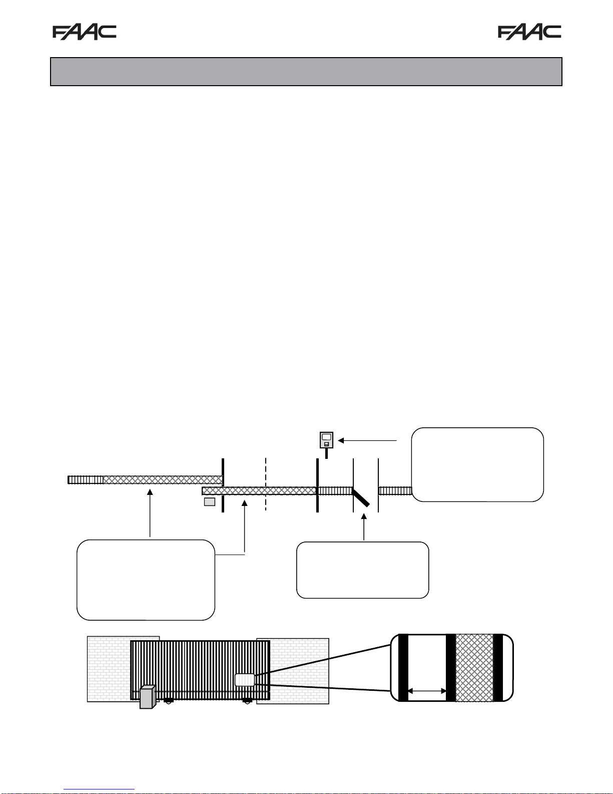
1. Refer to the diagram below for placement of non-contact sensors.
2. Use care to reduce the risk of nuisance tripping, such as when a vehicle trips the sensor while the gate is still moving.
3. One or more non-contact sensors shall be located where a risk of entrapment or obstruction exists, such as the
perimeter reachable by a moving gate or barrier. Use caution when installing non-contact sensors since some
devices only cover a select area. For example, a photo beam will not cover the full height of a gate/fence area.
Refer to the diagram below.
Open beams help protect
areas between the gate and
the adjacent fence. CAUTION:
This beam should be used in
conjunction with a contact
sensor.
Fence
Vehicular Gate Only
Protect against all entrapments
areas that exist:
1. Between the gate and the adjacent
fence when the gate is in the open
cycle
2. The gate operator and the slide gate
when the gate is in the open and
close cycles
3. At the front end of the gate when the
gate is in the close cycle.
Access
Fence Fence
Pedestrian
Close beams help
prevent the gate from
hitting obstructions
during the close cycle.
FSL700 Slide Gate Operator 5
Page 6
Contact Sensors (Edge Sensors):
Contact sensors generally are sensing edges or like devices. For gate operators utilizing contact sensors:
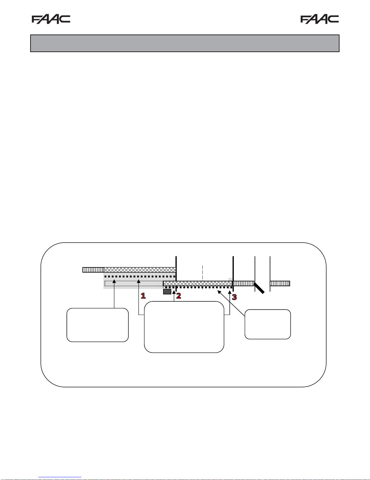
1. Refer to the diagram below for placement of contact sensors.
2. One or more contact sensors shall be located where the risk of entrapment or obstruction exists, such the leading
edge, trailing edge, and posts mounted inside and outside of the vehicular slide gate and motor.
3. Hardwired contact sensors shall be located and its wiring arranged so the communication between the sensor and the
gate operator is not subject to any mechanical damage.
4. Wireless contact sensors such as ones that transmit radio frequency (RF) signals to the gate operator for entrapment
prevention functions shall be located where the transmission of the signals are not obstructed or impe ded by building
structures, landscaping or similar obstructions. All wireless contact sensors shall function under the intended end-use
conditions.
I
MPORTANT
I
MPORTANT
Fence
S
AFETY
S
AFETY
I
NFORMATION
I
NFORMATION
Post edge sensors
help protect areas
inside and outside of
the gate and around
the operator
Access
Fence Fence
Pedestrian
Trailing edge sensor
helps protect areas between the gate and the
adjacent fence.
= Edge Sensor
Protect against all entrapments
areas that exist:
1. Between the gate and the adjacent
fence when the gate is in the open
cycle
2. The gate operator and the slide gate
when the gate is in the open and
close cycles
3. At the front end of the gate when the
gate is in the close cycle.
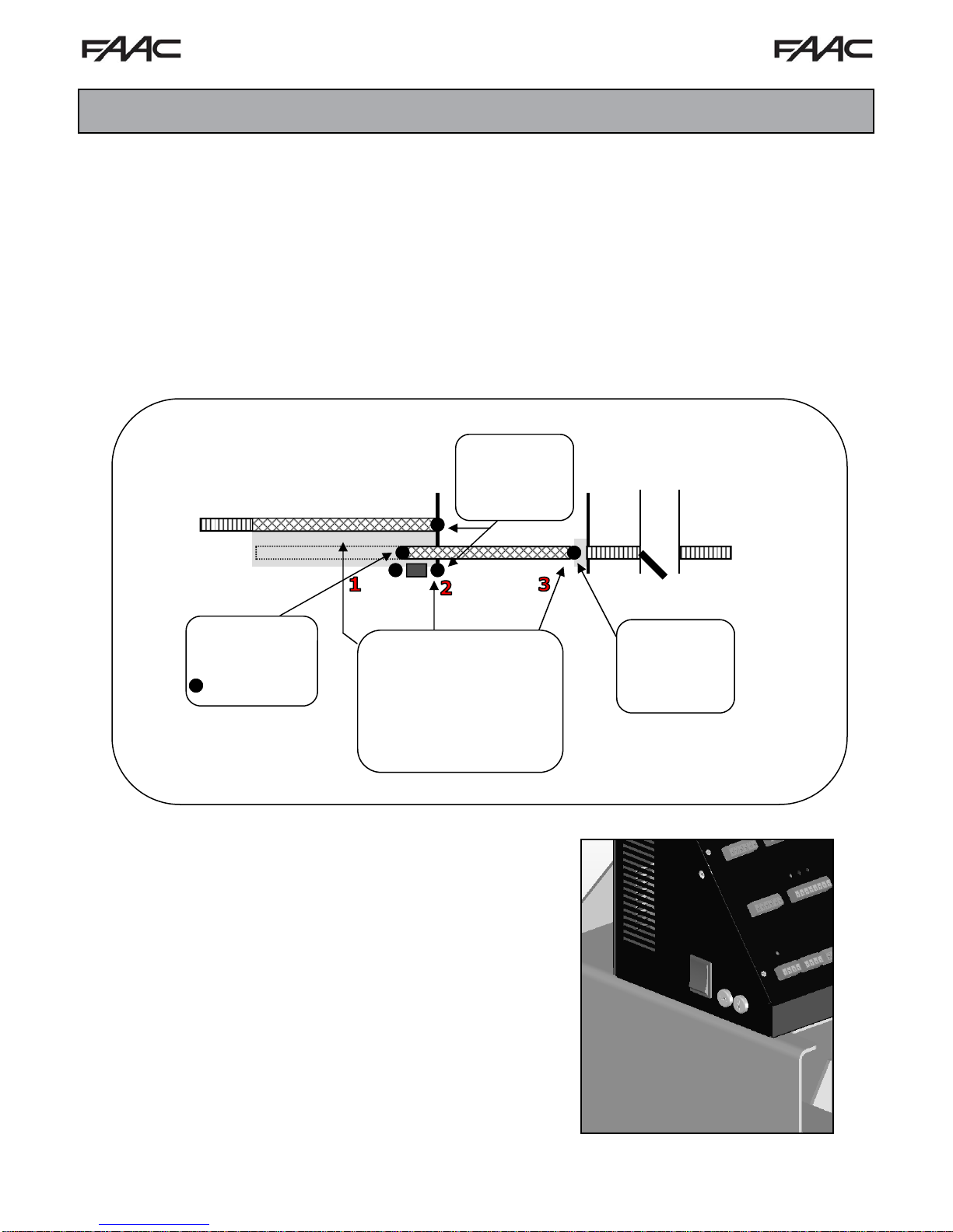
ANUAL RELEASE:
M
To manually release the gate operator remove the cover and locate
the Power ON-OFF switch.
Turning the power OFF allows the gate to be moved manually.
Turning the power back ON will resume normal operation.
Leading edge sensor
helps protect areas in
front of the gate.
FSL700 Swing Gate Operator 6
Page 7

I
MPORTANT
I
MPORTANT
IMPORTANT: Make sure the gate operator usage classification is correct for the site
!
and the type of gate.
S
AFETY
S
AFETY
I
NFORMATION
I
NFORMATION
UL325 G
RESIDENITAL VEHICULAR GATE OPERATOR
CLASS I: A vehicular gate operator (or system) intended for use in a home of one
to four single family dwelling, or a garage or parking area associated therewith.
COMMERCIAL/GENERAL ACCESS VEHICULAR GATE OPERATOR
CLASS II: A vehicular gate operator (or system) intended for use in a commercial
location or building such as a multi-family housing unit (five or more single family
units), hotels, garages, retail store, or other building servicing the general public.
INDUSTRIAL/LIMITED ACCESS VEHICULAR GATE OPERATOR
CLASS III: A vehicular gate operator (or system) intended for use in an industrial
location or building such as a factory or lading dock area or other locations not
intended to service the general public.
RESTRICTED ACCESS VEHICULAR GATE OPERATOR
CLASS IV: A vehicular gate operator (or system) intended for use in a guarded
industrial location or building such as an airport security area or other restricted
access locations not servicing the general public, in which unauthorized access is
prevented via supervision by security personnel.
ATE OPERATOR CLASSIFICATION:
ABC Apartments
ABC Manufacturing
Regional Airport
GLOSSARY OF TERMS:
GATE: A moving barrier such as a swinging, sliding, raising, lowering, or the like, barrier, that is a stand-alone passage barrier
or is that portion of a wall or fence system that controls entrance and/or egress by people or vehicles and completes the
perimeter of a defined area.
VEHICULAR HORIZONTAL SLIDE GATE OPERATOR (Or System): A vehicular gate operator (or system) that controls a
gate which slides in a horizontal direction that is intended for use for vehicular entrance or exit to a drive, parking lot, or the
like.
ENTRAPMENT: A condition when a object is caught or held in a position that increases the risk of injury or death.
INHERENT ENTRAPMENT SENSING DEVICE: An automatic sensor system, which senses entrapment of a solid object and
is incorporated as a permanent and integral part of the gate operator.
NON-CONTACT SENSOR: External device such as a photoelectric cell used to provide entrapment prev ention and located
where a risk of entrapment or obstruction exists.
CONTACT SENSOR: External device such as a edge sensor used to provide entrapment prevention located where a risk of
entrapment or obstruction exists such as the leading edge, trailing edge, and posts mounted inside and outside of the vehicular
slide gate and motor.
FSL700 Slide Gate Operator 7
Page 8
I
MPORTANT
I
MPORTANT
S
AFETY
S
AFETY
I
NFORMATION
I
NFORMATION
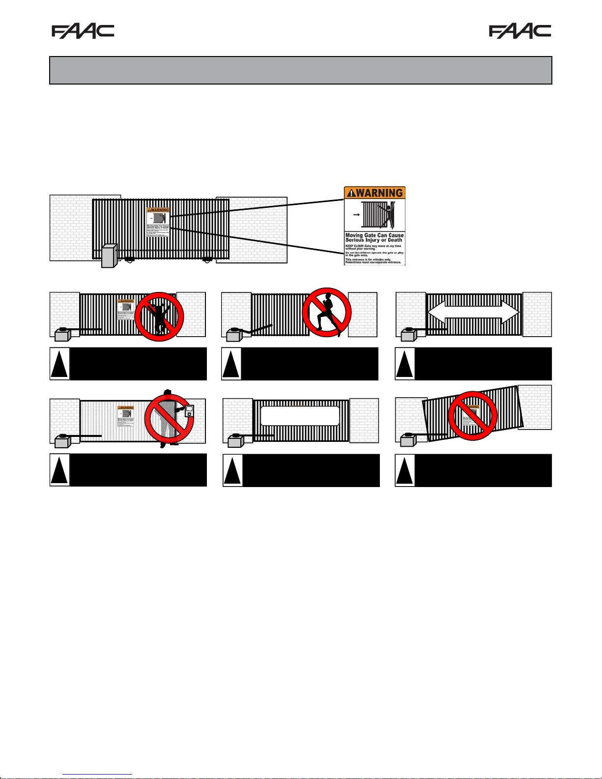
WARNING SIGN INSTALLATION:
This vehicular gate operator is supplied with two warning signs to alert people that a potential hazard may exist and that
appropriate action should be taken to reduce the risk of hazard, injury or death.
1. Warning signs must be permanently installed on both sides of the gate and must be fully visible to traffic and
pedestrians.
2. Use appropriate hardware such as metal screws (not supplied) to permanently install each warning sign.
INSTALLATION PRECAUTIONS:
DO NOT allow children to play
near, on or with the gate, gate
!
operator, or any of its controls.
DO NOT mount operating devices
accessible through the gate or in
!
between the gate and wall.
DO NOT allow pedestrian use of the
vehicular gate. No one should cross
!
!
the path of a moving gate!
1000 lb. Maximum
DO NOT mount the gate operator
to a gate heavier than 1000 lbs.
Maximum gate weight = 1000 lbs.
!
!
40 Feet Maximum
DO NOT mount the gate operator
to a gate longer than 40 feet.
Maximum gate length = 40 feet.
DO NOT mount the gate operator
on uphill or downhill applications.
Do not allow gate to free swing.
PREINSTALLATION GUIDELINES:
Before starting any installation, consider the following guidelines:
Install the gate system and gate in accordance with ASTM F220-02: Standard Specification for Automated Vehicular
Gate Construction. Install the gate system and gate in accordance with UL325 standards.
Provide spacing between the gate and any structure such as a building, wall or fence to reduce the risk of entrapment
in this area.
Install over-travel stops at both ends of the gate rail or track to help prevent the gate from derailing
Be sure the gate is properly installed and moves freely. Repair or replace worn or damaged gate hardware before
installing the gate operator.
Add safety devices such as warning signs, photo eyes, and reverse edges to help prevent injuries or death. Reduce
all pinch points and protect all entrapment areas.
If pedestrian traffic will be present, provide a separate pedestrian walk gate clear from the path of the automatic gate.
Loops and loop detectors are required to help prevent the gate from closing on vehicles. Loops do not protect
pedestrian traffic.
Select the proper gate operator for the installation. Consider the usage, capacity, gate size, gate weight, and needed
features and safety accessories.
If proper safety guidelines can not be followed do not install the gate operator.
FSL700 Slide Gate Operator 8
Page 9
T
ECHNICAL
T
ECHNICAL
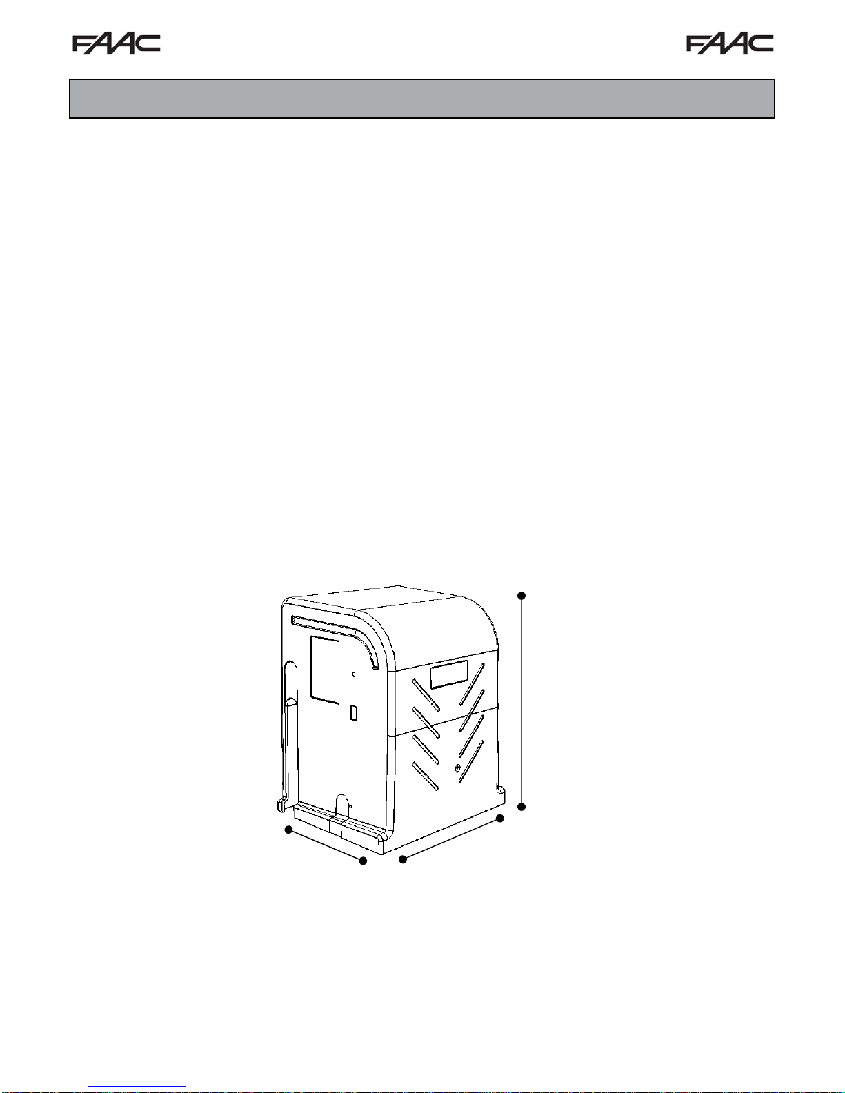
GATE OPERATOR SPECIFICATIONS:
Type of Gate ............................................................................. Vehicular Slide Gate Only
Horse Power ............................................................................. 1/2 HP, 500 Watt
Power Input ............................................................................... 120 VAC
Current ...................................................................................... 6A
Cycles/Hour .............................................................................. 75
Travel Speed ............................................................................ Approx 12 inches / sec
Maximum Gate Weight ............................................................. 1000 lbs
Maximum Gate Length .............................................................. 40 Feet
Primary Entrapment Protection ................................................. Inherent Current Sensor
Secondary Entrapment Protection ............................................ Provisions for Non-Contact & Contact Sensors
UL325 Class of Operation ......................................................... Class I, II, II, IV
S
PECIFICATION
S
PECIFICATION
FSL700 Slide Gate Operator 9
22”
”
1
5
”
8
1
Page 10
G
G
ATE
ATE
O
PERATOR
O
PERATOR
I
NSTALLATION
I
NSTALLATION
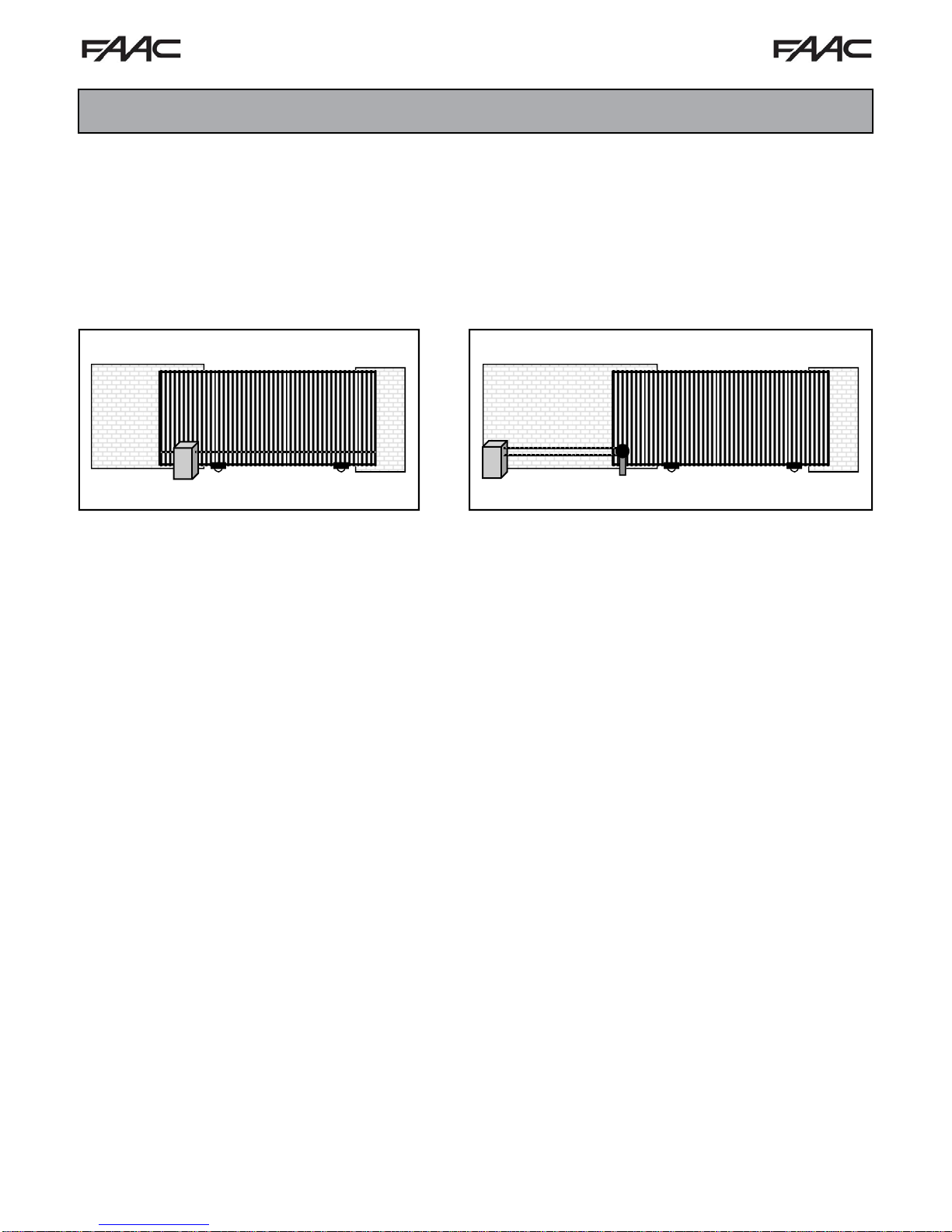
ATE OPERATOR LOCATION:
G
Select a location for the gate operator to be installed prior to pouring the concrete pad. There are two ways to mount a slide
gate operator: the traditional front mount, or the rear mount method. Both methods have their advantages and will reliably
open the gate.
F
RONT MOUNT METHOD:
The front mount method places the operator up front
near the flow of traffic and uses a single chain across
the length of the gate. The advantages and
disadvantages include:
Advantages:
Less chain is required for the application
saving money and time.
Does not require the use of an additional idler
sprocket saving money and time.
Less room is needed for the application and
allowing the operator to be more accessible for
service.
Disadvantages:
The operator is up front near the flow of traffic
allowing for a vehicle to damage the operator
more easily.
The chain runs across the length of the gate
allowing visitors to see and possible tamper
with it.
R
EAR MOUNT METHOD:
A rear mount installation places the operator at the back of the
gate and uses a double chain with an additional idler sprocket.
The advantages and disadvantages include:
Advantages:
The chain is attached to the rear of the gate and is not
visible when the gate is closed.
The operator is in the back away from the flow of traffic
for added safety.
The operator is in the back allowing more room for tight
parking conditions.
Disadvantages:
Twice as much chain is required for this type of
application = added expense.
The application requires the use of an additional idler
sprocket = added expense.
FSL700 Slide Gate Operator 10
Page 11

G
G
ATE
ATE
O
PERATOR
O
PERATOR
I
NSTALLATION
I
NSTALLATION
CONCRETE PAD SIZE & LOCATION:
The FSL700 vehicular gate operator is designed to be mounted on a concrete pad. Select a location for the gate operator to
be installed. For pad location and size:
1. Determine the location for the operator to be installed. (Front Mount v. Rear
Mount)
2. Follow all local building codes to determine the required depth of the concrete
pad. The average concrete pad should be 24” wide x 24” long x 24” deep.
3. Extend the pad 4” above ground and 24” below ground.
4. When the exact location of the operator can be predetermined, all conduits may
be located in the concrete pad terminating directly under the operator. Extend
each conduit a minimum of 1” above the level of the concrete pad. See the
Conduit Location diagram below. It is suggested to install a minimum of four (4)
conduits: (1) High Voltage Conduit, (1) Low Voltage Conduit , (1) Loop Lead
Wire Conduit, (1) Accessory Conduit.
5. When the exact location of the operator can not be predetermined, bring all conduits up to one side and terminate in a
Bell Box. Make connections to the operator using water-tight flex conduit.
6. Form the concrete pad as shown and pour concrete. Allow the concrete to cure for 48 hours before removing the
forms and mounting the operator.
7. Do not place mounting bolts in the concrete while pouring. Bolts may drift in wet concrete making the operator
location inaccurate.
8. NOTE: The path of the gate and gate track must be installed on concrete. The average gate track concrete should
be a minimum of 10” wide x 12” deep the entire length of the gate track and travel. Failure to place the gate track on
concrete can result in track movement and cause gate failure or derailment.
24”
4”
24”
24”
Distance From
Gate to Operator
Frame (3.5”)
3.5”
12.5”
GATE (2” x 2” Frame)
Available
Conduit
Area
14” Wide x 12.5” Deep
14”
17”
1.25” Distance From
Gate To Cover
2.75”
Distance From
Gate To Chain
Gate
Bracket
WARNING: Install over-travel stops at both ends of the gate rail or track for all types
!
FSL700 Slide Gate Operator 11
of installations to help prevent the gate from derailing.
Page 12

G
G
ATE
ATE
O
PERATOR
O
PERATOR
I
NSTALLATION
I
NSTALLATION
GATE OPERATOR BOLT DOWN
To align the operator to the gate and bolt it down:
1. Remove the gate operator cover and place the operator on the concrete pad. Position the operator with a distance of
3.5” from the gate to the back frame of the operator. IMPORTANT: Make sure the gate and operator are parallel and
level with each other.
2. Mark the mounting holes and remove the operator. Drill the mounting holes to the required depth and diameter for the
sleeve anchors being used. It is recommended to use 3/8” x 4” sleeve anchors. The use of sleeve anchors allows
greater flexibility and makes the installation and alignment much easier.
3. Clean the mounting holes and install the sleeves. Position the operator over the anchors. Recheck to make sure the
gate and operator are parallel and level with each other. Tighten the anchor bolts to securely hold the o perator.
90
CORRECT
GATE
GATE
OPERATOR
3.
! WRONG !
GATE
E
T
A
G
R
O
T
A
R
E
P
O
CHAIN CONNECTION - FRONT MOUNT
Once the gate operator is securely bolted down, the chain may be attached. To attach the chain for a front mounted system:
1. Make sure the chain will be in a straight line and same height as the lower idler sprockets.
2. Weld the chain brackets to the end of each side of the gate and level with the lower idler sprockets. (Approximately 11”)
3. Route the chain through the operator, over the first lower chain idler, under the chain sprocket, and over the second
lower idler.
4. Connect the chain bolts to eac h end of the chain using the supplied master links. Connect the chain bolts to the chain
brackets. Adjustments to the chain length should be made now.
5. Tighten the chain using the chain bolts so the chain does not sag more than one (1) inch per 10 feet of travel. Do not
over tighten!
CORRECT
GATE
! WRONG !
GATE
GATE
OPERATOR
CORRECT
Approx.
11”
FSL700 Slide Gate Operator 12
GATE
OPERATOR
! WRONG !
Page 13

G
G
ATE
ATE
O
PERATOR
O
PERATOR
I
NSTALLATION
I
NSTALLATION
CHAIN CONNECTION - REAR MOUNT
Rear mount operators require the use of an endless idler assembly and twice as much chain. Approximately 1 foot of added
opening space is needed. Once the gate operator is securely bolted down, the chain may be installed for a rear mount system.
1. Adjust the chain idler sprocket inside the gate operator for a rear mount application. Remove the lower idler on the
unused side and move it to the upper idler hole on the chain side of the operator. Both chain idlers should be above/
below each other.
2. Increase the cover chain slot on the chain si de of the operator. (Side toward the gate opening)
3. Close the gate and mount an end less idler assembly near the back of the gate. The chain must extend beyond the back
of the gate. IMPORTANT: Only use an endless idler assembly with a safety guard to prevent pinch and entrapment
points.
4. Adjust the height of the endless idler sprocket so the chain from the lower chain idler is level with the bottom of the
endless idler. (Approximately 11”) Make sure the chain will be in a straight line and same heig ht as the lower idler
sprocket.
5. Weld the bottom chain bracket to the end of the gate and le vel with the top of the endless idler sprocket. (Height
depends upon the size of the endless idler sprocket)
6. Weld the top chain brackets to the end of the gate a nd level with the top of the upper idler sprocket. (Approximately 15”)
7. Route the chain through the operator, over the upper chain idler, around and under the chain sprocket, and over the
lower idler.
8. Route the lower chain under a nd around the endless idler assembly.
9. Connect the chain bolts to each end of the ch ain using the supplied master links. Connect the chain bolts to the chain
brackets. Adjustments to the chain length should be made now.
10. Tighten the chain using the chain bolts so the chain does not sag more than one (1) inch per 10 feet of travel. Do not
over tighten!
WARNING: DO NOT INSTALL this product unless all safety standards are followed and
!
FSL700 Slide Gate Operator 13
all entrapment and pinch points have been eliminated.
Page 14

G
G
ATE
ATE
O
PERATOR
O
PERATOR
I
NSTALLATION
I
NSTALLATION
LIMIT SWITCH SETUP:
The gate operator uses a limit switch assembly to adjust the distance of travel. These adjustments should be made before
power is supplied to the operator. To adjust the distance of travel using the limits:
1. Turn power OFF! Use the power switch on the side to assure AC and Battery power are both OFF.
2. Manually move the gate fully to the right. Push the limit guide plate down and roll the top limit nut until it activates the
top limit switch. The switch will click when activated.
3. Manually move the gate to the left. Push the limit guide plate down and roll the bottom limit nut until it activates the
bottom limit switch. The switch will click when activated.
4. Release the limit guide plate and make sure it is engaged in the slots of each limit nut.
5. Readjust the limit nuts as necessary to fine tune the full-open and full-closed positions.
RIGHT
LEFT
GATE OPERATOR DIRECTION:
The gate operator uses a DIP switch setting to determine the open and close direction. To set the Open/Close direction:
1. Turn power OFF! Use the power switch on the side to assure AC and Battery power are both OFF.
2. Standing inside the gate looking at the gate operator, determine if the gate opens to the LEF T or RIGHT.
3. If the gate opens to the LEFT, move DIP SWITCH 6 to the Left.
4. If the gate opens to the RIGHT, move DIP SWITCH 6 to the Right.
Opens LEFT
Switch
6:
FSL700 Slide Gate Operator 14
Opens
Switch
6:
Page 15

E
LECTRICAL
E
LECTRICAL
I
NSTALLATION
I
NSTALLATION
POWER SWITCH LOCATION:
The gate operator uses a built-in power switch to control power to the operator and controller. This switch should be turned
OFF during installation and service. Failure to use this switch can result in unexpected gate movement. Please note:
1. The switch is located on the LEFT side of the control box.
2. DOWN position = OFF. UP position = ON.
3. This switch must be used to turn OFF AC and battery power. Only disconnecting AC power still allows battery power
to the operator, controller, and accessories.
4. Turn OFF until the installation is complete.
AC POWER GUIDELINES:
Under normal conditions, the gate operator will use a single phase AC power line to ope rate the gate, charge the batteries, and
power gate accessories. Use the following guidelines when installing the AC power:
1. Check the local wiring codes in all cases and follow all local building codes. Wiring and hookup should be performed
by a qualified electrician/installer only.
2. AC power should be supplied from a circuit breaker panel and must have its own dedicated circuit breaker. This
supply must include a green ground conductor.
3. Only use U.L. approved 14 AWG or larger 600 Volt Insulated Wire. Use the following chart to determine the AC wire
size. This information is for suggested use only - Check your local codes before installation.
4. Properly ground the gate operator to minimize or prevent damage from power surges and/or lightning. Use a
grounding rod if necessary. A surge suppresser is recommended for additional protection.
Wire Size: 14 Gauge 12 Gauge 10 Gauge 8 Gauge 4 Gauge
Distance: 250 Feet 400 Feet 650 Feet 1000 Feet 2000 Feet
AC P
To connect AC power to the gate operator:
OWER CONNECTION:
1. Turn the circuit breaker for the AC gate operator power OFF before connecting the AC input wires.
2. Turn the Power Switch OFF located on the left side of the controller before connecting the AC input wires.
3. Connect the AC input wires to the AC terminal located on the bottom/center of the control box. See diagram below.
4. Batteries must be installed after the AC power is on. See Battery Power Connection.
L N
GREEN = Ground
WHITE = Neutral
BLACK = 120 VAC
FSL700 Slide Gate Operator 15
Page 16

E
LECTRICAL
E
LECTRICAL
I
NSTALLATION
I
NSTALLATION
BATTERY POWER CONNECTION:
If AC power is connected, the system does not need the batteries to function. However, the batteries must be connected for
the Power Fail Battery Backup features to operate. When AC power is active, the batteries will charge until fully charged.
Once the batteries have fully charged, the system will stop charging. Charging is automatic when AC po wer is available. T he
system should be prewired with the batteries. If not, to connect batteries to the system:
1. Connect the RED wire from the Battery + Terminal to the positive terminal of the first battery.
2. Connect the BLACK wire from the Battery - Terminal to the negative terminal of the second battery.
3. Connect a jumper between the remaining terminals of each battery.
!
Batteries should be tested regularly for proper battery backup operation.
RED
BLACK
Batteries should be replaced each year or as needed.
+
-
+
-
12VDC, 8 amp
Battery
12VDC, 8 amp
Battery
ACCESSORY POWER:
Two plug-in power plugs are located on the back of the controller. These plugs are for low voltage accessories and ar e
separately fused. Low voltage, low current draw transformers may be plugged into these outlets for accessory power. DO
NOT USE THESE POWER OUTLETS FOR INSTALLATION OR SERVICE TOOLS. Each plug supplies 110 VAC when AC
power is active to the gate operator. If AC is not available, the power plugs will not supply power. Accessories requiring power
during battery backup modes should use the 24 VDC located on the controller terminals.
Additional accessory power may be found on the controller terminals. The controller terminals supply 24 VDC for accessories.
This power is available during AC and battery power modes. When AC power is active, accessori es will be supplied 24 VDC
without a power draw on the batteries. When the battery backup mode is active, accessories will be supplied 24 VDC fro m the
batteries. If the battery power mode is used frequently, consider the current draw of the accessories. The lower the current
draw, the longer the battery power supply will last. Additional 24 VDC for accessories may be found on the Radi o Terminal,
Edge/Photo Terminal, and External Loop Terminal. A connection between 24V DC+ and Common will supply power.
FSL700 Slide Gate Operator 16
Page 17

E
LECTRICAL
E
LECTRICAL
I
NSTALLATION
I
NSTALLATION
MASTER/SLAVE CONNECTION:
The operator can be used in a Master-Slave configuration to control the two leafs of a bi-partin g gate. T hat can be done with a
wired or wireless connection. The wired connection should be the default choice if there is a way to bring a cable across the
gate opening. If that’s impractical you can use the wireless connection accessory WMS100 to establish the communication
between Master and Slave. In the latter case you need to make sure there is no metal blocking the l in e of sight between the
two operators, for example a metal gate with no openings.
To connect two operators together:
1. Determine which operator is the Master and which operator is the slave. All external devices such as lo o p
detectors and safety devices must be wired directly to the Master unit. If one gate travels further than the other
the gate that travels further must be the Master
2. Turn Slave Operator DIP Switch 3 to ON = SLAVE
3. Turn Master Operator DIP Switch 3 to OFF = MASTER
4. WIRED CONNECTION: in a separate conduit, run a 6-conductor cable (twisted pairs) between the Master operator
and the Slave operator. Make the connections on the Master/Slave Terminal Block following the schematic below.
(Recommended Wire: Outdoor Rated CAT 5 Cable. If shielded make sure the shield is connected on one side only)
OR
4. WIRELESS CONNECTION: Plug one WMS100 board on the RJ45 connector on the top left of the Master control
board and one on the Slave. Wire the 24V power to it from one of the accessory terminal blocks.
5. Power up the operators and verify that the SLAVE LEDs are blinking
Master
WIRELESS Connection
Gate Operator
Slave
Gate Operator
Master
Switch 3:
OFF
FSL700 Slide Gate Operator 17
24 VDC
COM
WIRED Connection
[GND[ to [GND] BROWN
[TX+] to [RX+] GREEN
[TX–] to [RX–] GREEN-WHITE
[RX+] to [TX+] ORANGE
[RX–] to [TX–] ORANGE-WHITE
Slave
Switch 3:
ON
Page 18

G
G
ATE
ATE
O
PERATOR
O
PERATOR
A
DJUSTMENTS
A
DJUSTMENTS
REVERSE SENSITIVITY ADJUSTMENT:
The gate operator is equipped with an inherent (Type A) entrapment sensing system. The sensor detects obstructions in both
the open and close path of the gate. There is an OPEN SENSITIVITY Adjustment and a CLOSE SENSITIVITY Adjustment.
To adjust the sensitivity:
1. Activate the gate to open.
2. While the gate is running open, slowly rotate the OPEN SENSITIVITY adjustment clockwise to INCREASE the
sensitivity until the gate stops in mid-travel.
3. Gently rotate the OPEN SENSITIVITY adjustment counter-clockwise 1/8 turn to DECREASE the sensitivity.
4. Activate the gate to close.
5. While the gate is running closed, slowly rotate the CLOSE SENSITIVITY adjustment clockwise to INCREASE the
sensitivity until the gate stops in mid-travel.
6. Gently rotate the CLOSE SENSITIVITY adjustment counter-clockwise 1/8 turn to DECREASE the sensitivity.
7. Operate the gate a few times to be sure it fully cycles without stopping.
8. Place an immobile object in the open path of the gate to stop the gate while in travel. The gate should stop and enter
a Soft Shutdown upon striking the object.
9. Place an immobile object in the closed path of the gate to stop the gate while in travel. The gate should stop and
enter a Soft Shutdown upon striking the object.
10. Repeat steps 2 - 6 until the correct sensitivity adjustment is found.
For the Reverse Sensor to function correctly, the gate must be properly installed and work freely in both directions.
!
Repair or replace worn hardware. DO NOT use sensitivity to compensate for a gate in need of service.
Clockwise Turn:
INCREASE Sensitivity
(Reverse the gate more easily)
Counter-Clockwise Turn:
DECREASE Sensitivity
(Reverse the gate less easily)
CAUTION:
Gently rotate each
adjustment. Turning
the adjustment POT
too hard will break the
adjustment.
REVERSE SENSITIVITY SHUTDOWN:
Upon a first obstruction, the reverse sensor should:
1. Stop the gate and reverse it approximately two (2) inches.
2. Disable the Timer To Close Feature until the gate operator receives a new command = Soft Shutdown.
3. Any standard input can reactivate the gate and return it to normal operation.
Upon a second consecutive obstruction before the gate reaches either limit, the reverse sensor should:
1. Stop the gate.
2. Disable the gate operator = Hard Shut Down.
3. Sound the audio alarm for five (5) minutes or until the operator has been reset.
4. Only resetting the operator will reactivate the gate and return it to normal operation.
5. To reset the operator in a Hard Shut Down situation: Press the reset button on the left side of the controller or turn
the power switch OFF and back ON.
FSL700 Slide Gate Operator 18
Page 19

G
G
ATE
ATE
O
PERATOR
O
PERATOR
A
DJUSTMENTS
A
DJUSTMENTS
CLOSE TIME DELAY ADJUSTMENT:
The gate operator is equipped with a built-in automatic timer to close feature. This feature should be set to the OFF position
until proper safety and reverse devices have been installed. CAUTION: Turning on the Close Time Delay without proper
safety and reverse devices can cause serious injury, death, and property damage. The Close Time Delay can be set to from 1
to 90 seconds. When active, the Close Time Delay will hold the gate open until the internal timer has timed out and then
allows the gate to close. To turn OFF/ON and adjust the Close Time Delay:
1. To turn OFF the Close Time Delay, move DIP SWITCH 4 to the Left.
2. To turn ON the Close Time Delay, move DIP SWITCH 4 to the Right.
3. Turn power Off and back On to reset DIP Switch settings.
4. Rotate the TIME DELAY adjustment clockwise to INCREASE the delay.
5. Rotate the TIME DELAY adjustment counter-clockwise to DECREASE
the delay.
Clockwise Turn:
INCREASE Time Delay
(Holds gate open longer time)
Counter-Clockwise Turn:
DECREASE Time Delay
(Holds gate open shorter time)
Switch 4:
Timer ON
ON
CAUTION:
Gently rotate each adjustment. Turning the
adjustment POT too hard will break the
adjustment.
DIP SWITCH SETTINGS
The DIP Switches located on the top right face of the controller are used to set several different functions. This list gives a
brief description. The factory setting is in bold print. Please review each individual section in this manual for more detail.
Switch Function Description
1 Alarm
2 Anti-Tailgate
3 Master / Slave
4 Close Timer
5 Power Fail Cycle / Open
6 Open Left / Right
7 Quick Close
8 Stop (NO / NC)
9 Battery Cycle
10 Mag / Solenoid Delay
11 Tamper Detect
12 Hard Start
OFF: Sounds the built-in alarm in shutdown applications only.
ON: Beeps while gate is moving. Sounds the alarm in shutdown applications.
OFF: Gate opens and closes normal.
ON: Uses loops to control vehicles individually.
OFF: Operator is set as a Master (Primary).
ON: Operator is set as a Slave (Secondary).
OFF: Time Delay Close feature is inactive. Command to open, command to close.
ON: Time Delay Close feature is active. Gate opens, times out, closes.
OFF: During power failure, gate will cycle using BBU until batteries are too low to function.
ON: During power failure, gate will open and remain open until AC power is restored.
OFF: Opens the gate Left. (Standing inside looking out at operator)
ON: Opens the gate Right. (Standing inside looking out at operator)
OFF: Gate opens and closes normal.
ON: Gate opens until loops are cleared. Then close gate even if gate did not reach full open position.
OFF: Allows a NO Stop Switch to be used.
ON: Allows a NC Stop Switch to be used. Stop Switch must be installed for this setting to be ON.
OFF: Cycles gate until batteries are too low and stops. Switch 5 must be OFF.
ON: Cycles gate until batteries are too low and then opens gate. Switch 5 must be OFF.
OFF: No delay - activates gate immediately
ON: Delays 2 seconds before activating gate. Allows time for Maglock to discharge.
OFF: Gate opens and closes normal.
ON: If a closed gate is forced off limit, alarm sounds, motor stops open movement and closes gate.
OFF: Normal Soft Start, Soft Stop mode.
ON: Operator starts with 40% motor power for more starting torque. Normal start = 5% motor power.
FSL700 Slide Gate Operator 19
Page 20

A
CCESSORY
A
CCESSORY
ACCESSORY WIRE OVERVIEW:
C
L
O
S
E
E
D
G
E
O
P
E
N
E
D
G
E
CLOSE
Photo Cell
OPEN
Photo Cell
Radio
Receiver
C
ONNECTIONS
C
ONNECTIONS
FIRE
LOCK
Card Access
1 2 3
4 5 6
7 8 9
* 0 #
Phone Entry
1 2 3
4 5 6
7 8 9
* 0 #
Key Box
STOP
CLOSE
OPEN
FSL700 Slide Gate Operator 20
Page 21

A
CCESSORY
A
CCESSORY
C
ONNECTIONS
C
ONNECTIONS
EDGE SENSOR CONNECTIONS:
The gate operator has a Close Edge Terminal and an Open Edge Terminal for added control of the Sensing Edge functions.
The following chart describes the functions for a Close Edge Sensor and an Open Edge Sensor:
Close Edge Input:
1. Input is only active during close cycle.
2. An input during the close cycle will stop and reverse the
gate to the full open position.
3. If an Open Edge Input is active before reaching the full
open position, the gate will stop and enter a soft
shutdown.
4. If the gate reaches the full open position and the Time
Delay Close is ON, the gate will time out and close.
5. If the gate reaches the full open position and the time
Delay Close is OFF, the gate will remain open until a
close input is received.
6. If a second Close Edge Input is received while closing,
the gate will stop and enter a soft shutdown.
To connect a Sensing Edge:
1. Refer to the “External Entrapment Prevention” section of this manual for
guidelines and placement.
2. Connect Close Edge Sensors to EDGE CLOSE and COMMON.
3. Connect Open Edge Sensors to EDGE OPEN and COMMON.
C
L
O
S
E
E
D
G
E
O
P
E
N
E
D
G
E
Open Edge Input:
1. Input is only active during open cycle.
2. An input during open cycle will stop and reverse the gate
to the full closed position and enter a soft shutdown.
3. NOTE: If the gate was initially activated by a time clock
with a contact closure across the Access Input, this input
will be ignored until another input (Open Loop, Reverse
Loop, etc.) is received.
4. If a Close Edge input is active before reaching the full
closed position, the gate will stop and enter a soft
shutdown.
Edge Sensor Notes:
1. One or more contact sensors shall
be located where the risk of
entrapment or obstruction exists,
such the leading edge, trailing
edge, and posts mounted inside
and outside of the vehicular slide
gate and motor.
2. Hardwired contact sensors shall
be located and its wiring arranged
so the communication between
the sensor and the gate operator
is not subject to any mechanical
damage.
3. Wireless contact sensors such as
ones that transmit radio frequency
(RF) signals to the gate operator
for entrapment prevention
functions shall be located where
the transmission of the signals are
not obstructed or impeded by
building structures, landscaping or
similar obstructions. All wireless
contact sensors shall function
under the intended end-use
conditions.
4. Wireless contact sensors should
be checked on a regular basis.
Batteries should be replaced on a
regular basis.
5. Use only UL325 compliant
devices and follow all installation
guidelines set forth by the
FSL700 Slide Gate Operator 21
Page 22

A
CCESSORY
A
CCESSORY
C
ONNECTIONS
C
ONNECTIONS
PHOTO SENSOR CONNECTIONS:
The gate operator has a Photo Close Terminal and an Photo Open Terminal for added control of the Photo Sensor functions.
The following chart describes the functions for a Photo Close Sensor and a Photo Open Sensor:
Photo Close Input:
1. Input is only active during close cycle.
2. An input during the close cycle will stop the gate.
3. The gate will remain stopped until the input is cleared.
4. When the Photo Close is cleared, the gate will continue
to close.
To connect a Photo Sensor:
1. Refer to the “External Entrapment Prevention” section of this manual for guidelines and placement.
2. Connect the Photo Close Sensor to PHOTO CLOSE and COMMON.
3. Connect the Photo Open Sensor to PHOTO OPEN and COMMON.
4. For Photo Sensors that use 24VDC power, connect power to +24VCD and COMMON.
OPEN
Photo Cell
CLOSE
Photo Cell
Photo Open Input:
1. Input is only active during open cycle.
2. An input during open cycle will stop the gate.
3. The gate will remain stopped until the input is cleared.
4. When the Photo Open is cleared, the gate will continue
to open
.
Photo Sensor Notes:
1. Use care to reduce the risk of
nuisance tripping, such as
when a vehicle trips the
sensor while the gate is still
moving.
2. One or more non-contact
sensors shall be located
where a risk of entrapment or
obstruction exists, such as the
perimeter reachable by a
moving gate or barrier. Use
caution when installing noncontact sensors since some
devices only cover a select
area. For example, a photo
beam will not cover the full
height of a gate/fence area.
Refer to the diagram below.
3. Use only UL325 compliant
devices and follow all installation
guidelines set forth by the
manufacturer.
FSL700 Slide Gate Operator 22
Page 23

A
CCESSORY
A
CCESSORY
C
ONNECTIONS
C
ONNECTIONS
STANDARD REVERSE CONNECTIONS:
The Standard Reverse Terminal is for applications when an external device may be used as a standard reverse. For example:
Photo Sensors connected to this terminal will operate the same as a Reverse Loop. This connection should not be used for
Safety Reverse Devices. Use Edge and Photo inputs for proper Safety connections.
Standard Reverse Input:
1. Input is inactive when gate is closed or in the open cycle.
2. When gate is open and Time Delay Close is ON, an
input will reset the Time Delay Close.
3. When gate is open and Time Delay Close is OFF, an
input will prevent the gate from closing.
4. When gate is closing, an input will reverse the gate.
Connecting Standard Reverse Devices:
1. Connect to STD REVERSE and COMMON
2. For Devices that use 24VDC power, connect power to
+24VCD and COMMON
Standard
REVERSE
Device
OPEN, CLOSE, STOP CONNECTIONS:
The gate operator may use an external Open, Close, Stop (3-Button) to control the gate. The controller has built-in button
controls above each terminal for setup and testing.
Open, Close, Stop Input:
1. OPEN: Allows external input to OPEN gate.
2. CLOSE: Allows external input to CLOSE gate.
3. STOP: Allows external input to STOP gate.
Connecting Standard Reverse Devices:
1. Connect Open Button to OPEN and COMMON.
2. Connect Close Button to CLOSE and COMMON.
3. Connect Stop Button to STOP and COMMON.
STOP
CLOSE
OPEN
EXTERNAL RESET CONNECTION:
An external Reset Button may be connected to the Reset Terminal and used to reset the operator during Hard Shutdown
situations. During a Hard Shutdown, the operator can only be reset through the reset input or reset button on the left side of
the controller. The Reset Input can also be used during installation to reset the operator settings.
Reset Input:
1. Allows external input to reset gate operator during a
Hard Shutdown.
2. Allows external input to reset operator settings during
installation.
Connecting External Reset Devices:
1. Connect Reset Button to RESET and COMMON.
External
Reset
FSL700 Slide Gate Operator 23
Page 24

A
CCESSORY
A
CCESSORY
C
ONNECTIONS
C
ONNECTIONS
ACCESS CONTROL CONNECTION:
Access Control Devices such as Telephone Entry Systems, Digital Locks and Card Readers may be connected to the Access
Input to control the gate operator. When an Access Device is active, the Access LED will light.
Access Input:
1. Allows external Access Control Devices to activate the
gate.
2. If Close Time Delay is ON, gate will open and remain
open until the access device relay is released. Then the
gate will time out and close.
3. If Close Time Delay is OFF and the gate is in closed or
open position, gate will travel in the opposite direction.
4. If Close Time Delay is OFF and the gate is in mid cycle,
the gate will stop. The direction will not be changed until
another valid input is made.
Connecting Access Devices:
1. Connect Access Control Device relays to ACCESS and
COMMON. (Most devices use Normally Open &
Common)
2. Only connect devices that are in line of sight to this input.
If the access device is not in line of sight, connect it to
the radio input.
1 2 3
4 5 6
7 8 9
* 0 #
Card Access
Phone Entry
1 2 3
4 5 6
7 8 9
* 0 #
FIRE LOCK CONNECTION:
Fire Lock Controls such as Knox Locks and Fire Boxes may be connected to the Fire Input to control the gate operator. When
a Fire Lock Control is active, the Fire LED will light.
Fire Input:
1. Allows Fire Lock Controls to activate the gate.
2. This input knows the position of the gate and will only
open the gate when activated.
3. If Close Time Delay is ON, gate will open and remain
open until the fire control relay is released. Then the
gate will time out and close.
4. If Close Time Delay is OFF and the gate is in closed
position, gate will open and remain open until an
external input of any sort closes the gate.
5. If Close Time Delay is OFF and gate is in open position,
gate will remain open until an external input is made.
This prevents the Fire Input from closing the gate if in the
open position
Connecting Access Devices:
1. Connect Fire Lock Control relays to FIRE and
COMMON. (Most devices use Normally Closed &
Common)
FSL700 Slide Gate Operator 24
.
NOTE: Consult your local Fire Department for proper
building codes and Fire Lock requirements.
FIRE
LOCK
Page 25

A
CCESSORY
A
CCESSORY
C
ONNECTIONS
C
ONNECTIONS
RADIO RECEIVER CONNECTIONS:
Radio Controls may be connected to the Radio Inputs to control the gate operator. When a Radio Control is active, the Radio
LED will light.
Radio Input:
1. Allows Radio Controls to activate the gate and provides
24VDC.
2. NOTE: Wireless Edge Sensor Receivers should be
connected to the Edge Terminals. See page 19.
Connecting Generic Radio Receivers:
1. Connect Radio Relay to RADIO N.O. and RADIO
COMMON.
2. If the Radio Receiver uses 24VDC, connect Radio
Power to RADIO PWR +24VDC and RADIO PWR 24VDC.
Connecting FAAC XR2 Radio Receivers:
1. Connect XR2 N.O. relay contacts to RADIO N.O. and
RADIO COMMON.
2. Connect XR2 Power + to RADIO PWR +24VDC and
XR2 Power - to RADIO PWR -24VDC.
XR2
Radio
Receiver
MAGLOCK & SOLENOID LOCK CONNECTIONS:
Magnetic and Solenoid Locks may be connected to the controller and utilize a 2 second d elay on open to help dissipate
magnetic current or solenoid power for smoother openings.
MagLock & Solenoid Inputs:
1. Allows Maglocks and Solenoid Locks to be connected to
the gate operator with a 2 second delay to open.
2. Maglocks use a NC relay contact. Solenoid Locks use a
NO contact. Power must be applied externally.
Connecting Solenoid & Maglocks:
1. Set Master and Slave DIP Switch 10 to ON.
2. Connect Solenoids to the external power supply and
Solenoid Com and N.C. outputs following the schematic
on the left.
3. Connect Maglocks to the external power supply and
Maglock Com and N.C. outputs following the schematic
on the left.
Switch
10
MAGLOCK
SOLENOID
FSL700 Slide Gate Operator 25
Page 26

A
CCESSORY
A
CCESSORY
C
ONNECTIONS
C
ONNECTIONS
ALARM & WARNING LIGHT CONNECTIONS:
An external Alarm and/or external Warning Light may be connected to the gate operator. Devices connected to these
terminals will be active during shutdown applications and while the gate is in motion both open and closed if desired.
Alarm & Warning Inputs:
1. Allows an external Alarm to be active during shutdown
applications and also during gate motion if desired.
2. Allows external Warning Light to be active during gate
motion.
3. These outputs are NO relay contacts. Power must be
applied externally.
Connecting External Alarm & Warning Light:
1. Connect Warning Light to the external power supply and
Warning Com and N.C. outputs following the schematic
on the left.
2. Connect External Alarm to the external power suppl y
and Alarm Com and N.C. outputs following the
schematic on the left.
3. Set DIP Switch 1 to OFF for the Alarm to only sound in
shutdown applications.
4. Set DIP Switch 1 to ON for the Alarm to beep while gate
is moving and sound the alarm in shutdown situations.
EXTERNAL
ALARM
WARNING LIGHT
SOLAR PANEL CONNECTIONS:
For applications where AC Power drops out on a regular basis, an optional Solar Panel may be installed to help keep the
batteries charged.
NOTE: Solar and battery backup power are for limited operations and not intended for high traffic applications. Fully charged
batteries can operate a gate from 5 - 100 times depending on the application. Heavy gates, on hills, with poor hard ware are
going to operate fewer times than light gates, level, with good hardware.)
Solar Panel Inputs:
1. Allows an optional Solar Panel to be connected to the
system for added charging.
2. Output is limited to sunlight, gate application, battery
size, and Solar Panel output. To increase capacity,
increase the size of each Solar Panel.
Connecting Solar Panels:
1. Use one 20 Watt, 24VDC Solar Panel OR two 20 Watt,
12VDC Solar Panels together in series.
2. Connect the Solar Panel positive to SOLAR +
3. Connect the Solar Panel negative to SOLAR -
+
+
-
12VDC,
20 Watt
-
12VDC,
20 Watt
!
FSL700 Slide Gate Operator 26
Batteries should be tested regularly for proper battery backup operation.
Batteries should be replaced each year or as needed.
Page 27

L
OOPS
L
OOPS
& L
& L
OOP
OOP
D
ETECTORS
D
ETECTORS
BASIC LOOP LAYOUT:
The following diagram shows a typical slide gate application for t wo-way traffic or exit traffic. For one-way entry traffic, the exit
loop is not needed. (This diagram is a basic loop layout and does not show safety devices, pedestrian gate, fencing, etc.
Refer to “I
MPORTANT SAFETY INFORMATION” for gate details.)
OOP
L
REVERSE
4-5 Feet 4-5 Feet
OOP
L
REVERSE
OOP
L
OPEN
Vehicular Gate Only
LOOP INSTALLATION GUIDELINES:
Proper loop installation is a critical aspect of any gate application. An improper ly installed loop may operate intermittently
causing false triggers, holding the gate open, or allowing the gate to close on traffic. T he following guidelines should be
followed when installing loops:
1. Determine proper location and size of each loop. Chalk
out loops on the driveway:
Loops should be 4 - 5 feet back from the gate path. Loops any
closer may be cause false activation when the gate passes by.
Determine the size of the loop. Make the loop large enough so
a vehicle must pass over the loop. The average loop is 4’ x 8’.
Consider the detection height.
Determine the detection height. The typical sensing height is
2/3 of the shortest leg. (Example: a 4’ x 8’ loop typically has a
detection height of 2 1/2 feet.) To increase the detection height,
increase the loop size.
2. Cut loop slots in the driveway:
Loop slot should be 1 1/2” to 2” deep.
Loop slot should be 1/4” wide.
Cut diagonal corner slots to protect the wire insulation and keep
the wire from changing directions quickly.
3. Install loop wire:
Recommended Wire: 14 AGW to 18 AGW Stranded XLPE.
Starting at the gate operator, install the loop wire into the lead
and loop slots. Use one continuous run of wire for the loop.
Install the appropriate number of turns as determined by total
loop square footage. (Use attached chart)
Twist lead wires at least 6 turns per foot from the loop to the
loop input. (Hint: Pull the lead wires tight from the corner of the
loop and twist using a power drill.)
Route the lead wires to the edge of the driveway and into rigid
conduit under ground. Seal this joint to protect the wires.
Press the loop wire to the bottom of the loop slot. Use Backer
Rod (foam rubber) to protect and keep the loop wires from
rising when the sealant is poured.
Seal the loop slots with a sealant. Make sure the sealant is
able to sink to the bottom of the loop slot and completely
encase the loop wire. The wire should not move when the
sealant has set.
Diagonal
Corner Cuts
2”
Typical
Loop Size
(Sq. Feet)
6’ to 12’ 6
13’ to 20’ 5
21’ to 60’ 4
61’ to 240’ 3
241’ & Up 2
}
Typical
Loop
1/4” Saw Slot
Sealant: 3/4” to 1” Min.
Backer Rod
Loop Wires: 3 Turns
Number
Of Turns
Lead wires must be
twisted 6 twist/foot
until connected to the
loop input. If
possible, twist lead
wires from the edge
of the loop.
FSL700 Slide Gate Operator 27
Page 28

L
OOPS
L
OOPS
& L
& L
OOP
OOP
D
ETECTORS
D
ETECTORS
PLUG-IN LOOP DETECTOR CONNECTIONS:
The gate operator may utilize PLD1500 Plug-in Loop Detectors to simplify installation, save space a nd eliminate extra wiring.
There are three plug-in terminals (Shadow, Reverse, Open) located on the gate controller. Detectors plugged into a specific
socket will perform that function. To connect a PLD1500:
Plug-In Loop Detector Inputs:
1. Shadow Loop: Not used on FSL700.
2. Reverse Loop: Plug detector into center socket. Make
sure detector is secure and snapped in.
3. Open Loop: Plug detector into left socket. Make sure
detector is secure and snapped in.
4. Set different frequencies for each loop detector.
5. Follow the directions provided with the PLD1500 for
more detailed settings.
Ground Loop Wire Connections:
1. Connect Reverse Loops wires to REVERSE 1 and 2. For
fail safe operation connect reverse loops in series.
2. Connect Open Loop wires to OPEN 1 and OPEN 2.
OOP
L
REVERSE
4-5 Feet 4-5 Feet
OOP
L
REVERSE
Vehicular Gate Only
OOP
L
OPEN
EXTERNAL LOOP DETECTOR CONNECTIONS:
The gate operator may utilize external Loop Detectors. Refer to the manufacturer’s instructions for detailed wiring.
External Loop Detector Inputs:
1. 24VDC is available to power external loop detectors.
Connect 24VDC detector power to +24VDC and
COMMON.
2. Shadow Loop: Not used on FSL700.
3. Reverse Loop: Connect relay wires to REVERSE N.O.
and COMMON.
4. Open Loop: Connect relay wires to OPEN N.O. and
COMMON.
5. Set different frequencies for each loop detector.
6. Follow the directions provided by the external loop
detector manufacturer for more detailed settings.
FSL700 Slide Gate Operator 28
Page 29

T
ROUBLESHOOTING
T
ROUBLESHOOTING
T
T
IPS
IPS
FAULT LIGHT COUNT:
The gate operator control board has a Fault Light to help determine fault shutdowns. If the operator is not functioni ng properly,
remove the cover and check the Fault Light for the operator Fault Status. Use the following chart to determine the Fault:
Number of
Blinks
1
2
3
Fault Description
Sensitivity/Current
Overload:
First Time
Sensitivity/Current
Overload:
Second Time
Run Time Fault
Cause & Action
Operator detected an unexpected current overload while moving. Usually caused
by the gate hitting an obstruction or tripping the sensitivity. This will put the
operator in a Soft Shutdown.
1. Make sure the sensitivity settings are set correctly. Too light of a setting will
cause the gate to stop and fault.
2. Make sure there are no external obstructions that are causing the gate to stop
and shutdown.
Operator detected an unexpected current overload while moving a second time.
Usually caused by the gate hitting an obstruction or tripping the sensitivity. T his will
put the operator in a Hard Shutdown.
1. Make sure the sensitivity settings are set correctly. Too light of a setting will
cause the gate to stop and fault.
2. Make sure there are no external obstructions that are causing the gate to stop
and shutdown.
Operator has run longer than normal. Usually caused by a bad limit or wiring fault
1. Check the limit for normal operation.
2. Make sure the limit wires Connections are tight .
4
5
6
Sensor Fault/Failure
PCB Overheat Fault
Master Slave Fault
Motor Sensors have failed. Usually caused by a bad sensor or loose sensor wire.
1. Make sure the sensor wires are tight and well connected to the blue connector.
While the operator is stopped, wiggle the Limit/Sensor connector. If the limit or
sensor wires blink on and off, there is a loose connection.
2. Start the operator, watch Sensor 1 and Sensor 2 at startup. They should both
blink before turning solid. If only one blinks, then the non-blinking sensor is not
being seen.
3. Remove the motor from the gearbox. Both sensor lights should be on. Pass a
flat screw driver between Sensor 1 and Sensor 2 on the motor plate. The
Sensor LED on the control board should turn off and on as the screw driver
passed through it.
4. Make sure the sensor cup on the gearbox shaft is tight. A loose sensor cup will
slip and cause the sensors to miss counts.
Operator PCB has become too hot and caused a fault.
1. Make sure the control board heat sink is secured to the side of the controller box
to help dissipate excess heat.
2. Determine if the operator has run excessively to cause an overheating pro blem.
3. Possibly a defective heat sensor on the control board. Have board repaired.
Master Slave communication has failed. Usually caused by a loose Master Slave
wire or connector. A very strong lightning strike can sometimes cause damage to
the master slave circuit on the control board.
1. Make sure the master slave wires are connected correctly and tight.
2. Unplug the master slave wire and set both operators as Masters. Test each
operator independently to make sure there are no other problems or faults. After
determining each operator runs by itself, reset the master slave settings and
connect the master slave wire. If the problem continues, recheck wire and wire
connections.
3. Run a new CAT5 wire on top of the driveway to test the master slave
communication. This will determine if the underground wire is good or bad.
4. Possible damage to the control board master slave components. Have boards
repaired.
FSL700 Slide Gate Operator 29
Page 30

S
PARE
S
PARE
P
P
ARTS
ARTS
Num FAAC p/n Description
1 GC3101 Controller PCB with heat sink
2 GC3100 Controller PCB, heat sink and faceplate assembly
3 GC3000 Controller Assembly (No PCB, faceplate)
4 MOTOR-0500-24 Motor - 500W, 24VDC
5 SL-0020 Gearbox 15:1
6 SL1000+ Limit stand assembly with switches
7 3540 Battery (single)
8 SL-1001 Chain idler a ssembly
9 SL-0002 Chain sprocket
FSL700 Slide Gate Operator 30
Page 31

S
PARE
S
PARE
P
P
ARTS
ARTS
Num FAAC p/n Description
10 SL-0008 Limit nut guide
11 SWITCH-0100 Limit switch
12 AAA0450 Sensor cup assembly
13 WIRE1101SK Sensors wire assembly with screws
14 AAA-0402 Motor Adapter Plate
FSL700 Slide Gate Operator 31
Page 32

L
IMITED
L
IMITED
To the original purchaser only:
FAAC International, Inc., warrants, for sixty
(60) months from the date of invoice, this
gate operator system manufactured and distributed by
FAAC International, Inc. to be free from defects in material
and workmanship under normal use and service for which it
was intended provided it has been properly installed
and operated.
FAAC International, Inc.’s obligations under this
warranty shall be limited to the repair or exchange
of any part of parts manufactured by FAAC International,
Inc. and distributed by FAAC International, Inc.
Defective products must be returned to FAAC International,
Inc., freight prepaid by purchaser, within the warranty
period. Items returned will be repaired or replaced, at FAAC
International, Inc.’s option, upon an examination of the
product by FAAC International, Inc., which discloses, to
the satisfaction of FAAC International, Inc., that the item is
defective. FAAC International, Inc. will return the warranted
item freight prepaid. The products manufactured by FAAC
International, Inc. and distributed by FAAC International, Inc.
are not warranted to meet the specific requirements,
if any, of safety codes of any particular state, municipality, or
other jurisdiction, and FAAC International, Inc. doesn’t
assume any risk or liability whatsoever resulting from
the use thereof, whether used singly or in combination with
other machines or apparatus.
Any products and parts not manufactured
and distributed by FAAC International, Inc., will carry only
the warranty, if any, of the manufacturer. This warranty shall
not apply to any products or parts thereof which have been
repaired or altered, without FAAC International, Inc.’s written
consent, outside of FAAC International, Inc.’s workshop, or
altered in any way so as, in the judgment of FAAC
International, Inc., to affect adversely the stability or
reliability of the product(s) or has been subject to misuse,
negligence, or accident, or has not been operated in
accordance with FAAC International, Inc.’s instructions.
or has been operated under conditions more severe than, or
otherwise exceeding, those set forth in the specifications for
such product(s). FAAC International, Inc. shall not be liable
for any loss or damage whatsoever resulting, directly or
indirectly, from the use or loss of use of the product(s).
Without limiting the foregoing, this exclusion from liability
embraces a purchaser’s expenses for downtime or for
making up downtime, damages for which the purchaser
may be liable to other persons, damages to property, and
injury to or death of any persons.
W
ARRANTY
W
ARRANTY
FAAC International, Inc., does not assumes nor authorizes
any person to assume for them any other liability in
connection with the sale or use of the products of FAAC
International, Inc. The warranty herein above set forth shall
not be deemed to cover maintenance parts, including, but
not limited to, hydraulic oil, filters, or the like. No agreement
to replace or repair shall constitute an admission by
FAAC International, Inc., of any legal responsibility to effect
such replacement, to make such repair, or otherwise. This
limited warranty extends only to wholesale customers who
buy directly through FAAC International, Inc.’s normal
distribution channels. FAAC International, Inc., does not
warrant its products to end consumers.
Consumers must inquire from their selling dealer
as to the nature and extent of that dealer’s warranty, if any.
This warranty is expressly in lieu of all other warranties
expressed or implied including the warranties of
merchantability and fitness for use. This warranty shall not
apply to products or any part thereof which have been
subject to accident, negligence, alteration, abuse, or misuse
or if damage was due to improper installation or use of
improper power source, or if damage was caused by fire,
flood, lightning, electrical power surge, explosion, wind
storm, hail, aircraft or vehicles, vandalism, riot or civil
commotion, or acts of God.
FSL700 Slide Gate Operator 32
 Loading...