

Page 1

Installation and Reference Manual
™
SwingSmart DC
SwingSmart DC 20
SwingSmart DCS 20 (solar)
Pad-mounted electromechanical swing gate operator with Smart DC Controller
800-321-9947 • www.hysecurity.com
Page 2

Page 3

SwingSmart DC 20 Gate Operator
SwingSmart DCS 20 Gate Operator
Installation and Maintenance Manual
D0149 - Revision E
Installation and Maintenance Manual
(14 June 2012)
HySecurity
Corporate Headquarters
6623 S 228th Street
Kent, WA 98032
Page 4
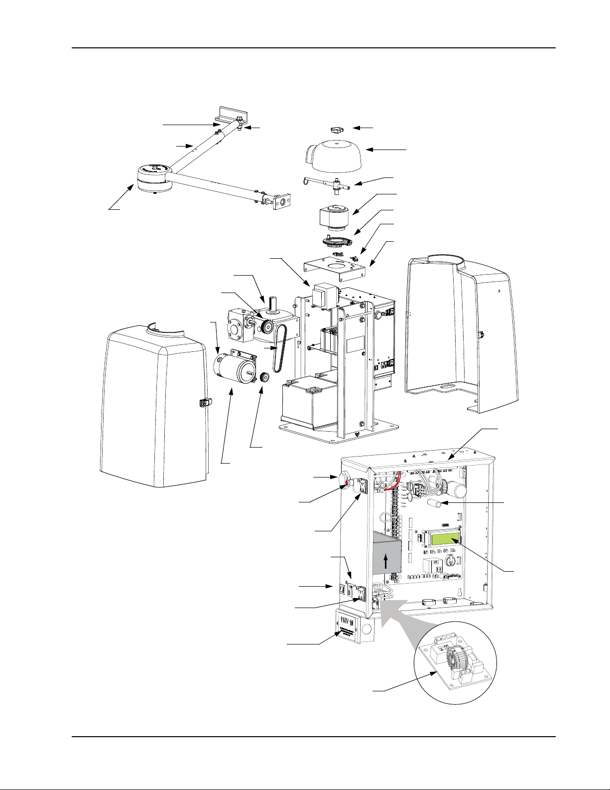
S
Board,
Smart DC
Board,
Power supply
Buzzer
Switch, Reset
DC Switch, On/Off
115VAC Service Outlet
Emergency Stop Button
Circuit breaker
AC Switch, On/Off
Junction box
Control Box
Display
Controller
Front Cover
Knob, Top Cap
Cover, Top Cap
Handle, Clamp
Taper Clamp Assembly
Limit Plate with Limit Cams
Limit Switch
Bracket, Limit Switch
Swivel Eye
Stub Arm
Arm Assembly
Cover, Pinch
Bolt
Transformer
Gearbox
Pulley, Gearbox
Pulley, Motor
DC Motor
Belt
Brush
Rear Cover
WINGSMART
C
OMPONENTS
SwingSmart Components
O
DC
POW
OF
Note: Refer to Parts & Limited Warranty for the SwingSmart parts list.
Service Outlet
115VAC, 15A
O
AC
POW
OF
Revision E Intro-1
Page 5

SwingSmart Components
Introducing SwingSmart DC
Contents
I
NTELLIGENT FEATURES
T
ECHNICAL SUPPORT
I
NSTALLER'S CHECK LIST
........................................................................................................................... INTRO-3
: S
MART
DC C
ONTROLLER
..................................................................................................................... INTRO-4
TM
....................................................................... INTRO-2
Safety Requirements
I
MPORTANT SAFETY INSTRUCTIONS
............................................................................................................... S-1
Safety Standards - Installer's Responsibility ............................................................................................... S-1
Safety Standards - Owner/User Responsibility ........................................................................................... S-3
Hazardous Materials and Proper Disposal ................................................................................................. S-4
S
ECONDARY ENTRAPMENT PROTECTION SENSORS
........................................................................................ S-5
Identifying Gate Operator Category and Usage Class ................................................................................ S-6
Choosing Secondary Entrapment Protection ............................................................................................. S-7
E
MERGENCY STOP BUTTON
E
MERGENCY RELEASE
W
IND LOAD FACTORS
S
AFETY NOTICES
C
OMMON INDUSTRIAL SYMBOLS
........................................................................................................................................... S-10
............................................................................................................................ S-8
...................................................................................................................................... S-8
& S
ITE PREP
............................................................................................................... S-9
.................................................................................................................. S-10
Chapter 1: Installation
S
ITE OVERVIEW
P
AD CONDITION
& P
LANNING
......................................................................................................................... 1-1
............................................................................................................................................. 1-2
Pouring the Concrete ................................................................................................................................ 1-2
Using an Existing Pad ............................................................................................................................... 1-4
U
NPACKING THE OPERATOR
M
OUNTING THE OPERATOR
G
ATE BRACKET AND LINKAGE ARMS
........................................................................................................................... 1-5
........................................................................................................................... 1-6
.............................................................................................................. 1-7
Installing the Gate Bracket ........................................................................................................................ 1-7
Attaching the Stub Arms ........................................................................................................................... 1-8
Installing the Linkage Arms ....................................................................................................................... 1-9
Adjusting the Limit Switches ................................................................................................................... 1-11
Completing Gate Arm Installation .......................................................................................................... 1-12
Articulating Arm Option ......................................................................................................................... 1-14
Setting the Taper Clamp ......................................................................................................................... 1-15
Locking the Gate Arm at Secure Facilities ............................................................................................... 1-16
Chapter 2: Power
I
NSTALLING THE EARTH GROUND
W
IRING
AC P
OWER
........................................................................................................................................ 2-3
.................................................................................................................. 2-1
Revision E Contents 1
Page 6

Contents
Wiring 115VAC Power .............................................................................................................................. 2-4
Wiring 208/230VAC Power ...................................................................................................................... 2-4
C
ONNECTING
U
SING
A S
DC P
OWER
............................................................................................................................... 2-6
OLAR POWERED OPERATOR
............................................................................................................ 2-6
Design Requirements & Considerations .................................................................................................... 2-7
Connecting the SwingSmart DCS 20 to Solar Power Panels ...................................................................... 2-8
Connecting Peripherals to Solar Operators .............................................................................................. 2-10
Understanding Gate Activity based on Solar Zones .................................................................................. 2-11
I
MPORTANT CONSIDERATIONS FOR
DC-
POWERED OPERATORS
.................................................................. 2-12
Installing the Extended Battery Backup Kit .............................................................................................. 2-13
Chapter 3: Display and Menu Options
I
NITIAL SETUP
Turning Both Power Switches On ............................................................................................................. 3-2
Using the Smart DC Controller Buttons In Menu Mode ........................................................................... 3-3
Configuring the Setup Menu ..................................................................................................................... 3-4
R
UN MODE
Understanding Gate Status Displays .......................................................................................................... 3-5
Using the Smart DC Controller Buttons In RUN Mode ........................................................................... 3-6
Viewing Operator Status Displays .............................................................................................................. 3-7
U
SER MENU
Adjusting the Close Timer ......................................................................................................................... 3-9
Setting the Time and Date ....................................................................................................................... 3-10
Setting AC Power Loss Gate Function ..................................................................................................... 3-11
Adjusting the Display Contrast ................................................................................................................ 3-12
I
NSTALLER MENU
Adjusting the Gate Speed ......................................................................................................................... 3-17
Adjusting the IES Sensitivity .................................................................................................................... 3-18
Reinstating Factory Defaults .................................................................................................................... 3-20
Enabling the Fire Department Override ................................................................................................... 3-21
.................................................................................................................................................. 3-1
...................................................................................................................................................... 3-5
..................................................................................................................................................... 3-8
.......................................................................................................................................... 3-16
Chapter 4: Smart DC Controller
O
VERVIEW OF THE SMART
Preliminary Testing .................................................................................................................................... 4-3
Vehicle Detector Installation Options ........................................................................................................ 4-4
Connecting HY-5A Vehicle Detectors ................................................................................................. 4-5
Installing Standard 11-Pin Box Type Vehicle Detectors ...................................................................... 4-7
Vehicle Detector Configuration and Quick Close Mode Selection ...................................................... 4-8
C
ONNECTING ACCESSORY DEVICES
Manual Push-button Station .................................................................................................................... 4-10
User Relays - Programming Procedure ..................................................................................................... 4-11
2 SwingSmart - Installation, Operation and Maintenence Manual Revision E
DC C
ONTROLLER
................................................................................................. 4-2
................................................................................................................ 4-9
Page 7

Contents
Chapter 5: Bi-parting Gate Systems
P
OWER REQUIREMENTS
M
ASTER AND SLAVE WIRING CONNECTIONS
M
ASTER AND SLAVE MENU SETUP
Chapter 6: Reference
C
ONNECTING A RADIO RECEIVER FOR REMOTE OPEN
I
NSTALLING A MAGLOCK OR SOLENOID LOCK
Installing a Lock for 12VDC or 24VDC Systems ...................................................................................... 6-3
Installing a Lock on 24VAC Systems ......................................................................................................... 6-4
Installing a Lock for High Voltage Systems ............................................................................................... 6-4
Setting the User Relay Function in the Installer Menu .............................................................................. 6-5
I
NSTALLING VEHICLE DETECTORS AND LOOPS
I
NSTALLING PHOTOELECTRIC SENSORS FOR SECONDARY ENTRAPMENT PROTECTION ONLY
Operation Notes: .............................................................................................................................. 6-11
Supervised Connection: .................................................................................................................... 6-12
Photo Eye Function: ......................................................................................................................... 6-12
I
NSTALLING GATE EDGE SENSORS
S
MART
DC C
ONTROLLER TROUBLESHOOTING
Vehicle Detector and Loop Fault Diagnostics .......................................................................................... 6-23
SwingSmart Schematics ........................................................................................................................... 6-25
G
ENERAL MAINTENANCE
Smart Touch Analyze and Retrieve Tool (S.T.A.R.T.) ............................................................................ 6-27
What You Need ................................................................................................................................ 6-27
Installing START Software ............................................................................................................... 6-27
Setting User Account Controls ......................................................................................................... 6-28
Electrical Controls ................................................................................................................................... 6-28
Mechanical Maintenance ......................................................................................................................... 6-29
Software Maintenance ............................................................................................................................. 6-29
Drive Belt Tension and Alignment ................................................................................................... 6-30
DC Battery Replacement .................................................................................................................. 6-31
Clock Battery Replacement ............................................................................................................... 6-33
.................................................................................................................................. 5-1
................................................................................................. 5-2
.................................................................................................................. 5-4
.................................................................................. 6-1
............................................................................................... 6-3
.............................................................................................. 6-6
.................... 6-10
................................................................................................................ 6-14
............................................................................................ 6-16
.............................................................................................................................. 6-27
Chapter 7: Parts & Limited Warranty
S
WINGSMART PARTS
S
WINGSMART PARTS LIST
L
IMITED WARRANTY
S
WINGSMART
DC S
Revision E Contents 3
...................................................................................................................................... G-1
.............................................................................................................................. G-2
...................................................................................................................................... G-3
PECIFICATIONS
................................................................................................................ G-4
Page 8

Contents
4 SwingSmart - Installation, Operation and Maintenence Manual Revision E
Page 9

Intelligent Features: Smart DC ControllerTM
Introducing SwingSmart DC
Thank you for purchasing our premium SwingSmart DC™ 20 swing gate operator. At HySecurity® Gate, Inc.,
we pride ourselves on quality and a number of unparalleled user benefits:
Robust - An especially strong twin channel steel chassis and adjustable taper clutch greatly improves the ability
for SwingSmart to resist damage from vehicle hits on the gate. The components on the Smart DC Controller
are protected by opto-isolators which shield them from power surges and lightning strikes.
Power - A variable speed control board supplies a powerful, continuous 24V DC motor which drives a 600:1
gearbox providing variable speeds. The electronics, motor and gear box are rated to operate in very broad
temperatures that range from -13°F to 158°F (-25°C to 70°C). SwingSmart DC is rated for gates up to 20 feet
long and 1,300 pounds.
Finesse - A variable rate of gate acceleration and deceleration, dependent upon gate weight and length, assures
very smooth handling.
Adaptable - The design incorporates left and right gate arms to assure aesthetic functionality. An articulating
arm is an available option which also provides adaptability to a variety of site situations.
UPS backup and Solar ready - Two 12V, 8 amp hour (Ah) batteries will provide a fully functional gate operator
(up to 300 gate cycles) when AC power is unavailable. Four user-selectable UPS modes are available. 12VDC
and 24VDC are available to power access controls. The unit’s design also incorporates space for optional 50Ah
batteries to support solar applications or usage during extended power outages.
I
NTELLIGENT
Automatic adjustment and synchronization of bi-parting gates - The Smart DC Controller automatically
adjusts the gate speed to synchronize the left and right gates so that they reach the open and close positions at
the same time. Independent leaf delay adjustment for bi-parting gates is selectable in ½ second increments.
Menus and User relays - The Smart DC Controller has 48 menu items to allow installer configuration of gate
function and two user relays, which can be configured for 22 different functions.
Independent adjustment for open and close gate speeds - An easy-to-use menu on the Smart DC Controller
allows the installer to vary the open and close speed settings in a range between 10 and 15 seconds.
Intelligent Inherent Entrapment Sensor (IES) - Any impediment to gate travel is sensed by the system, stopping
gate movement per UL 325 Safety Standards. The intelligent system monitors gate power then adapts the IES
to trip at an adjustable threshold above normal power.
Improved Liquid Crystal Display (LCD) - A 32-character LCD provides increased readability for programming
and troubleshooting.
F
EATURES
: S
MART
DC C
ONTROLLER
TM
USB communications port - A direct connect provides accessibility to download system diagnostics and upload
system configurations using the Smart Touch Analyze and Retrieve Tool (S.T.A.R.T.) software.
S.T.A.R.T. software and diagnostics - With S.T.A.R.T. software loaded on a laptop computer, you have an
invaluable management tool for all HySecurity operators. To download this free software, visit the HySecurity
website at www.hysecurity.com.
Intro-2 SwingSmart DC Installation and Refer ence Manual Revision E
Page 10

Technical Support
T
ECHNICAL
For technical support, call your installer or authorized HySecurity distributor. Obtain the serial number of your
operator before calling. Refer to SwingSmart Components on the front page. For the name of a distributor near
to your locale, call HySecurity at 800-321-9947.
For information about HySecurity training for installers, maintenance personnel and end-users, refer to the
company website at www.hysecurity.com or call 800-321-9947.
S
UPPORT
Revision E Introducing SwingSmart DC Intro-3
Page 11

Installer's Check List
I
NSTALLER'S
C
HECK
L
IST
The following list provides a high level overview of the tasks involved in installing the SwingSmart DC gate
operator. Take a moment to review the list and check off the items as you complete the install.
?
Site Prep - concrete pad location/dimensions/distance from gate, conduits and vehicle detector loops
properly installed, gate bracket and linkage arm mounting considerations.
?
Make sure gate installation complies with ASTM F2200 Specification for Automated Vehicular Gate
Construction and UL325 Safety Standards. Install supplied WARNING signs on both sides of the gate.
?
Check for compliance with local codes, site conditions, and NEC standards.
?
Install operator on concrete pad using four ½ - 13 x 3.5 inch long concrete wedge anchors.
?
Temporarily attach gate bracket and linkage arm(s).
?
Adjust open and close limit switches through manual operation of the gate.
?
Complete gate arm installation (weld or drill and bolt).
?
Cut the excess off the over extension stop (angle iron) on the SwingSmart arm.
?
Hand-tighten the taper clamp to obtain a tight clutch setting.
?
Install the earth ground and AC wiring connections for AC power.
?
Connect battery wire to switch.
?
Complete Initial Setup Menu programming.
?
Review the connections on the Smart DC Controller.
?
Install Master/Slave operator connections, if the site is a bi-parting gate system.
?
Attach accessory devices.
?
Configure the User and Installer Menu options. Program applicable settings dependent on accessory
devices installed.
?
Set the Close Timer (in the User Menu), if necessary.
?
Check the Smart DC Controller software version. If needed, upload the latest version from
www.hysecurity.com. See Smart Touch Analyze and Retrieve Tool (S.T.A.R.T.).
?
Give a copy of the operator instructions to the end user. Show the end user how to:
• Remove the operator covers. Turn the power off and on.
• Turn the DC power switch off, which disengages the motor.
• Loosen the taper clamp and manually push the gate(s) open & close.
Note: Remember to re-tighten the taper clamp before turning the DC power switch back on and
replacing the covers.
• Test the red Emergency Stop Button located on the side of the control box. It can be accessed through a
hole in the cover. See illustration on page S-8.
?
Take photographs of the completed installation site and save them in your business files.
Intro-4 SwingSmart DC Installation and Refer ence Manual Revision E
Page 12

Page 13

Important Safety Instructions
WARNING
!
Safety Requirements
Automatic gate operators provide user convenience and security. However, because these machines can produce
high levels of force, it is imperative that gate operator system designers, installers and end users be aware of
potential hazards associated with improperly designed, installed, or maintained systems. The gate operator is
only one component of the total gate operating system. It is the joint responsibility of the architect, site
designer, purchaser, installer and end user to verify that the total system is appropriately configured for its
intended use. Additionally, certain municipalities have established licensing, codes or regulations that regulate
automated gate system design and installation. Consult local government agencies for up-to-date rules and
regulations prior to gate system design or installation.
I
MPORTANT
A moving gate can cause serious injury or death. S.T.A.R.T. the gate operator only when the
gate’s travel path is clear.
S
AFETY INSTRUCTIONS
Hazards, associated with automatic gates, can be reduced with proper site design, installation, and use.
Installers, maintenance crews, and owners/users must read and follow the
manual and review all the literature that accompanies the product. It is important that only qualified installer’s
handle the installation of the SwingSmart gate operator. A “qualified” installer has one of the following:
• A minimum of three years experience installing similar equipment.
• Proof of attending a HySecurity Technical Training seminar within the past three years.
• Significant manufacturer endorsements of technical aptitude in gate operator installation and operation.
Underwriter Laboratories (UL) and the American Society for Testing and Materials (ASTM) are responsible for
current safety standards and regulations regarding gate operators and automated gates. To pass UL certification,
all aspects of gate installation must comply with the appropriate safety standards. For the most up-to-date,
ASTM F2200 Gate and Fence Standards, refer to www.astm.org. For UL 325 Safety Standard, refer to
www.ul.com.
Important Safety Instructions
Safety Standards - Installer's Responsibility
• Study the entire contents of this manual prior to installing, operating, or maintaining the SwingSmart gate
operator. Taking extra time to align the gate operator and verify a fully functional installation will reduce
maintenance, guarantee longest system life, and ensure customer satisfaction.
• Verify the gate operator usage class for the site. Refer to
for gate classifications. Install SwingSmart only when the gate operator class is correct for the site, size, and
type of gate.
• Install an automatic operator only on gates that comply with ASTM F2200 Gate and Fence Standards.
Screen or enclose openings in the gate per UL 325 Safety Standards.
Identifying Gate Operator Category and Usage Class
in this
Revision E Safety Requirements S-1
Page 14

Important Safety Instructions
NOTE
• Before attaching the operator to the gate, move the gate in both directions. Make sure it is level and moves
freely. A gate that swings easily reduces strain on operator components. Gravity should play no part in the
opening or closing of the gate.
• Make sure there is a separate walk-through entrance nearby. Make certain a clear pedestrian path is
designated and signs direct pedestrians to the walk-through gate. The automated gate entry is for vehicle
use only. No one should cross the path of a moving gate.
• Install the gate operator on the secure (non-public) side of the gate. Note that swing gates cannot open into
public areas. Locate controls (OPEN, STOP, CLOSE) where a user will have a clear view of the gate.
• Mount access control devices beyond reach of the gate. The control devices that operate the gate must be:
• Located in a clear line of sight to the gate.
• Mounted beyond 6 feet of the gate to prevent users from touching or accessing the gate while operating
the controls. People attempting to access the controls by reaching through or around the gate can be
seriously injured or killed by the moving gate.
• Incorporate a security feature to prevent unauthorized use.
• The gate operator must be properly grounded and the incoming power voltage must match the voltage
label on the junction box.
• Install enough external entrapment protection sensors so that pedestrians are protected from entrapment in
both directions of the gate travel and all hazard areas and possible pinch points are fully protected. Review
the information found in
• Install the supplied WARNING signs on the inside and outside of the gate so they are clearly visible from
both sides of the gate. Installing the signs is a requirement for UL 325 compliance.
• Locate controls (Open, Close, Stop/Reset) where a user will have a clear view of the gate. Refer to the
Emergency Stop Button
OPEN terminal.
• Connect radio and other remote access (non-resetting controls) to the RADIO OPTIONS terminals.
• Open and close the gate to confirm that it was properly installed and to ensure reduced risk of entrapment.
Verify the clearance between the gate and adjacent structures per UL 325 Safety Standards. Have a
qualified technician test the gate monthly.
• When you complete the installation, show the end user how to:
• Remove the operator covers and turn the power off and on.
• Turn the DC power switch off, which disengages the motor.
• Loosen the taper clamp and manually push the gate(s) open & close.
Secondary Entrapment Protection Sensors
. Connect radio and other remote access (non-resetting controls) to the REMOTE
.
Note: Remember to re-tighten the taper clamp before turning the DC power switch back on and
replacing the covers.
• Test the red Emergency Stop Button located on the side of the control box. It can be accessed through a
hole in the cover.
Gate operator instructions must be given to the owner per UL 325 Safety Standards.
S-2 SwingSmart DC Installation and Refer ence Manual Revision E
Page 15

Important Safety Instructions
WARNING
!
CAUTION
Safety Standards - Owner/User Responsibility
A moving gate can cause serious injury or death. Automatic gate operators move gates with high
force. Make sure gates and gate operators are installed to reduce the risks of entrapment. Verify
your gate and gate operator comply with UL 325 Safety Standards and ASTM F2200 Gate and
Fence Standards. Ask for a copy of the gate operator’s product literature and review it. You are
responsible for educating all gate system users about proper use of the automated gate system.
Failure to adjust and test the gate operator on a regularly maintained schedule can increase the risk
of injury or death.
• Automatic gates are for vehicular use only; provide and maintain walkways and signs to direct pedestrians
to a separate walk-through entrance.
• An automatic gate can S.T.A.R.T. at any time without warning; always keep people away from the gate
area.
• Never let children operate or play with gate controls. Keep all remote controls, especially radio
transmitters, away from children. Do not allow children to play on or around the gate, gate area, or gate
operators.
• Learn how to turn the power on and off. Learn how to manually release the gate.
Before attempting a manual release, make sure the gate is not moving.
• WARNING signs supplied with the gate operator must remain installed and clearly visible on both sides of
the gate. The signs are required to maintain UL 325 compliance.
• Never disable the Warn Before Operate buzzer and NEVER disconnect or cut its wires. The buzzer
provides an alert that the gate is about to move and it must be functional in the event of entrapment
regardless of UL 325 gate usage class. Disabling the warning buzzer may increase the risk or extent of
injury if entrapment occurs.
• Test the gate operator monthly. Specifically, test the primary Inherent Entrapment Sensor (IES) and
secondary entrapment protection sensors. The gate must reverse its direction of travel upon contact with a
rigid object and/or stop, when an object activates the non-contact sensors. After adjusting the force or the
limit of travel, retest the gate operator. Failure to adjust and test the gate operator on a regularly maintained
schedule can increase the risk of injury or death.
• Have a professional gate installer routinely test the entire gate operator and entrapment protection sensors.
Have a qualified service person make repairs to gate hardware to keep the gate running smoothly.
Revision E Safety Requirements S-3
Page 16

Important Safety Instructions
CAUTION
!
Hazardous Materials and Proper Disposal
SwingSmart uses sealed, state-of-the-art Absorbed Glass Mat (AGM) batteries and highly recommends
replacing used batteries with new AGM-type batteries.
The batteries used with the SwingSmart gate operator contain materials that are considered hazardous to the environment. Proper disposal of the battery is required by federal law. Refer to
federal guidelines found in
To reduce the risk of fire or injury to persons:
• Observe the polarity between the batteries and charging circuit.
• Never mix battery sizes, types, or brands. HySecurity strongly recommends that only sealed AGM style
batteries be used.
• Exercise care in handling batteries. Be aware that the metal found in rings, bracelets, and keys can conduct
electricity, short the batteries, and cause potential injury.
• Do not open or mutilate the batteries. Battery cells contain corrosive materials which may cause burns and
other injuries. The material within batteries is toxic.
• Always dispose of batteries properly. Do NOT place batteries in fire. The battery cells may explode. Follow
federal guidelines for proper disposal of hazardous waste.
• Replace batteries according to the instructions found in
Hazardous Waste Regulations
.
DC Battery Replacement
.
S-4 SwingSmart DC Installation and Refer ence Manual Revision E
Page 17

Secondary Entrapment Protection Sensors
CAUTION
!
S
ECONDARY
SwingSmart is equipped with a primary, Type A, inherent entrapment sensor (IES). UL 325 Safety Standard
compliance requires installation of secondary entrapment protection sensors, the number of which, depends on
the entrapment hazards that exist at each particular installation.
To comply with UL 325, the following external sensors may be used:
• Contact sensors, such as edge sensors
• Non-contact sensors, such as photoelectric eyes
The site designer or installer can choose either photoelectric eyes or edge sensors or use these devices in
combination. Whatever devices are used, protection in both the opening and closing directions of gate travel
must be provided.
The UL 325 Safety Standard for automatic swinging gates specifically requires that edge sensors or
photoelectric eyes or a combination of both devices be installed to protect against pedestrian entrapment in
BOTH directions of the gate travel and where an entrapment hazard exists.
E
NTRAPMENT
P
ROTECTION
S
ENSORS
PHOTOELECTRIC EYES:
obstruction exists, such as the perimeter reachable by a moving gate.
A photoelectric eye or contact sensor is also required to protect against possible entrapment if
the gate opens to a position less than 16 inches (40.6cm) from any object, such as a post or wall.
EDGE SENSORS:
gate where the risk of entrapment or obstruction exists. If the bottom edge of the swing gate is situated more
than 6-inches (152 mm) above ground level at any point in its arc of travel, one or more contact sensors must
be located on the bottom edge, as well.
SENSOR SECURITY:
between the sensor and gate is not subjected to mechanical damage.
SENSOR FUNCTION and COMMUNICATION:
must be located so its signal is not impeded by building structures or other obstructions. All sensors must be
installed so that they function as intended for the end-use conditions.
UL 325 LISTING:
Components” under UL 325 in order to be deemed acceptable for use in a gate operator. Study the
Safety Instructions
Locate edge sensors and/or photoelectric sensors accordingly.
Be certain that a sufficient number of sensors are used so that pedestrians are protected from entrapment in
both directions of the gate travel and all hazard areas are fully protected. Refer to the UL website at
www.ul.com for the most up-to-date list of gate operator safety standards (UL 325). Refer to www.astm.org for
a complete list of ASTM F2200 Gate and Fence Standards.
One or more edge sensors shall be located on the inner and outer leading edge of a swing
The edge sensors and photo electric eyes must be tested and labeled as “Recognized
and consider your specific installation to determine where the greatest entrapment risks exist.
One or more photoelectric eyes shall be located where the risk of entrapment or
A hard-wired sensor shall be located and its wiring arranged so that communication
A sensor that transmits its signal to the gate operator
Important
Revision E Safety Requirements S-5
Page 18
Secondary Entrapment Protection Sensors
Identifying Gate Operator Category and Usage Class
The SwingSmart operator, according to UL 325 Safety Standards, falls in the Swing Gate and Vertical Barrier
Arm category for gate operators. It’s usage class is determined by the area that the vehicular gate services.
Four different vehicular usage classes are defined by UL 325:
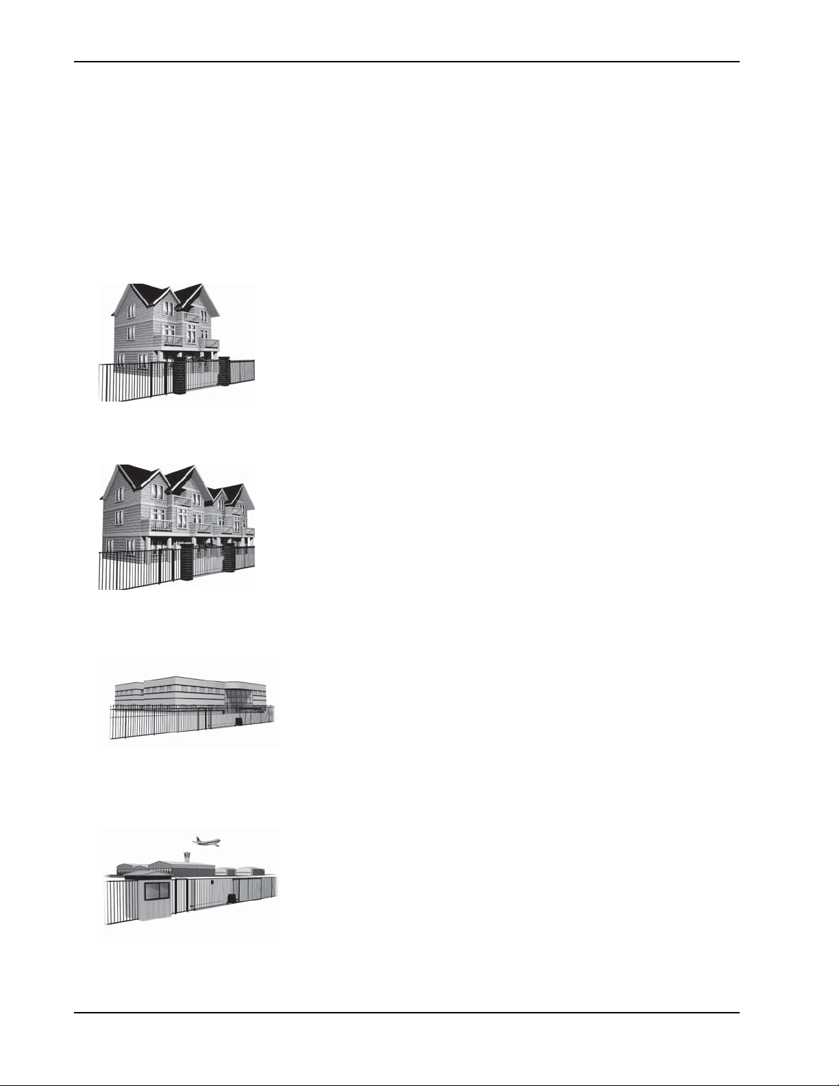
Class I
Class I: Intended for use in a location of one to four single family dwellings or a
parking area associated with one to four single family dwellings.
Class II
Class III
Class IV
Class II: Intended for use in a commercial location or building such as a multifamily housing units (five or more single family units) hotels, garages, retail stores
or other buildings servicing the general public.
Class III: Intended for use in an industrial location or building such as
factories or loading docks or other locations not intended to service the
general public.
Class IV: Intended for use in guarded industrial locations or buildings such
as an airport security area or other restricted access location, not servicing
the general public, in which access is monitored by security personnel or via
closed circuitry.
S-6 SwingSmart DC Installation and Refer ence Manual Revision E
Page 19
Secondary Entrapment Protection Sensors
NOTE
CAUTION
Choosing Secondary Entrapment Protection
The site designer or installer must determine which secondary entrapment sensor devices will be installed with
the SwingSmart operator to meet UL compliance. The type of entrapment sensor device systems are described
below. For a complete listing of the requirements, see UL 325 Safety Standards.
SwingSmart is equipped with a primary, Type A, inherent entrapment sensor (IES) that complies with UL 325. Any impediment to gate travel causes the gate to stop and reverse.
Usage Class Primary Type Device Secondary Type Device
Class I, II, III A B1, B2, C, or D
Class IV A B1, B2, C, D, or E
To comply with UL 325, refer to the chart and take the following steps:
1. Select the Usage Class according to the gate’s locale and purpose.
2. The required UL 325 primary Type A sensor is an integral part of the SwingSmart system.
3. Based on the gate’s usage class, choose Secondary Type Devices: B1, B2, C, D, or E.
• To comply using B1 - install non-contact sensors (photoelectric sensor or the equivalent).
• To comply using B2 - install contact sensors (edge sensor device or the equivalent).
• To comply using a Type D device requires a CONSTANT HOLD push-button station. This CONSTANT
HOLD push-button station must be the only device that opens and closes the gate. It can only be used where
the gate and push button station will be monitored by personnel 24 hours a day in full view of the gate area.
An automatic closing device (such as a timer, loop sensor, or similar device) must not be employed. A Warning
placard stating, “WARNING - Moving Gate has the Potential of Inflicting Injury or Death - Do Not
S.T.A.R.T. the Gate Unless the Path is Clear” must be placed adjacent to the gate operator controls.
While compliance is possible with Type C, which is a low force limiting clutch, the SwingSmart
operator develops more gate actuation force than is permitted under the UL 325 Safety Standards and, therefore, its clutch cannot be considered an entrapment protection device.
Similar compliance issues exist with a Type E device (audio warn before operate alarm). A Type
E device is permitted as a means of secondary entrapment protection by UL 325 in Class IV
applications, but it is not recommended by HySecurity because a buzzer warns, but cannot
protect against possible entrapment. HySecurity highly recommends, even for Class IV use, that
secondary entrapment protection (edge or photo-eye sensor) devices be installed to detect
possible entrapment.
Revision E Safety Requirements S-7
Page 20
Emergency St op Button
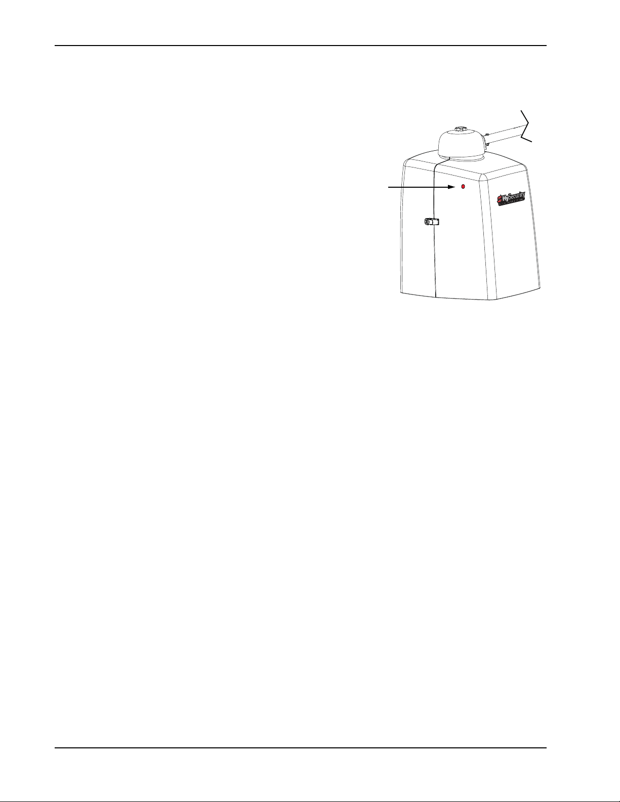
Red
Emergency
Stop button
E
MERGENCY
An emergency stop button that is accessible from the
outside of the operator is a requirement for compliance
with UL325 Safety Standards. The red emergency stop
button on the SwingSmart operator is located inside a hole
cutout on the cover.
Pressing the emergency stop button while the gate is
opening or closing disables the automatic close timer and
stops gate travel. The gate travel remains stopped until the
operator receives any open or close signal.
Make sure all users of the gate know where the emergency
stop button is located.
A screwdriver or hex key can be used to press lightly on the
switch to activate it.
S
TOP
B
UTTON
E
MERGENCY
Make sure to teach all users how to turn off electric power and how to move the gate manually. SwingSmart
allows a gate to be pushed manually when the taper clamp is loosened. It is recommended that you turn off DC
power which disengages the motor allowing you to easily move the gate.
When you turn DC power off, the following occurs:
• The motor disengages which keeps it from running should any relay or open/close leaf functions be set.
• The GATE NO LOAD (FAULT 4) may appear on the display.
To manually open the gate(s), take the following steps:
1. Remove the covers and turn off.
2. Extend the taper handle and loosen the clamp by turning the handle counter-clockwise. Refer to
Figure 1-16 on page 1-15.
3. Swing the gate(s) open or close.
To return SwingSmart to automatic operation, take the following steps:
1. Make sure the gate(s) is not moving.
2. Tighten the taper clamp until no slippage occurs when you simulate a gate strike. Refer to
Clamp
on page 1-15.
R
ELEASE
Setting the Taper
3. Flip the DC power switch ON.
4. Clear any faults by pressing STOP or RESET.
S-8 SwingSmart DC Installation and Refer ence Manual Revision E
Page 21

Wind Load Factors & Site Prep
CAUTION
!
W
IND
Wind load is always a factor when considering the appropriate gate for a particular site. Solid gate panels
produce a larger wind load than gates with slats or open decorative features. If you are installing a gate operator
in high wind areas, the gate design will affect the load on the gate operator. Because wind force acts the same as
an obstruction, it is important that gates be designed to present a relatively low surface area for the wind to
push on the gate panel.
If the gate is heavy and near the weight capacity of what the gate operator can handle (see specifications for
SwingSmartDC on the back cover), make sure it has an open design that allows wind to flow through it. A
solid or semi-solid gate design under certain wind load conditions may cause damage to the gate operator and
is not covered by the HySecurity Limited Warranty.
Several factors play into the calculations of the wind load on a gate panel. To find out the maximum wind
speed in areas around the United States, search for US government wind speed maps on the internet. If you
don’t know how to calculate for wind load, ask a mechanical engineer or site architect for assistance prior to
installing the gate operator and gate panels.
SwingSmartDC incorporates a primary Type-A inherent entrapment sensor (IES) into its design per UL 325
Safety Standards. (More information about adjusting the adapative IES software can be found in this manual
under,
reverse direction. This feature may be falsely triggered in excessively windy conditions because the wind itself,
acting over the surface area of the gate panel, can provide the necessary force to trigger the IES.
L
OAD
Adjusting the IES Sensitivity
F
ACTORS
& S
.) When the IES trips, it sends a signal to the gate operator to stop and
ITE
P
REP
Do not adjust IES sensitivity to accommodate for inappropriately designed gate panels. Loss of
IES sensitivity increases mechanical wear on the gate hardware and the gate operator. It may
also pose a safety hazard. Compensating for wind loads by adjusting the IES may set the IES
sensitivity to a level which, when encountering an obstruction, ignores the obstruction and fails
to reverse direction. For more information, refer to
Adjusting the IES Sensitivity
.
Revision E Safety Requirements S-9
Page 22
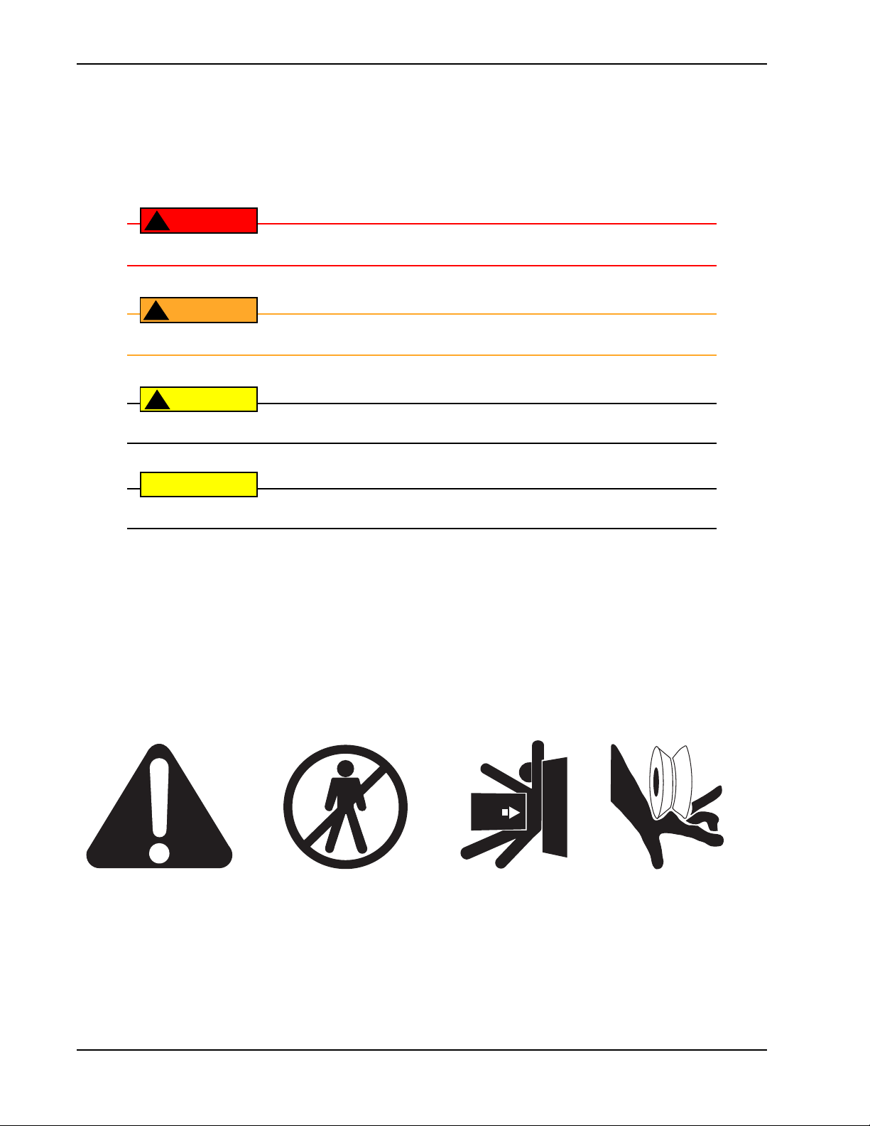
Safety Noti ce s
DANGER
!
WARNING
!
CAUTION
!
CAUTION
Attention
- Take Note -
- Danger -
Keep Away
Entrapment
Zone
Possible
Pinch Point
S
AFETY
The following four levels of safety notices are used where applicable within this manual; each notice contains
information specific to the situation.
N
OTICES
Indicates death or serious injury
Indicates death or serious injury
Indicates mild or moderate injury
Indicates damage to equipment
C
OMMON INDUSTRIAL
The following international safety symbols may appear on the product or in its literature. The symbols are used
to alert you to potential personal injury hazards. Obey all safety messages that follow these symbols to avoid
possible injury or death.
will
occur if the hazardous situation is not avoided.
could
occur if the hazardous situation is not avoided.
could
occur if the hazardous situation is not avoided.
is probable
if the hazardous situation in not avoided.
S
YMBOLS
S-10 SwingSmart DC Installation and Reference Manual Revision E
Page 23
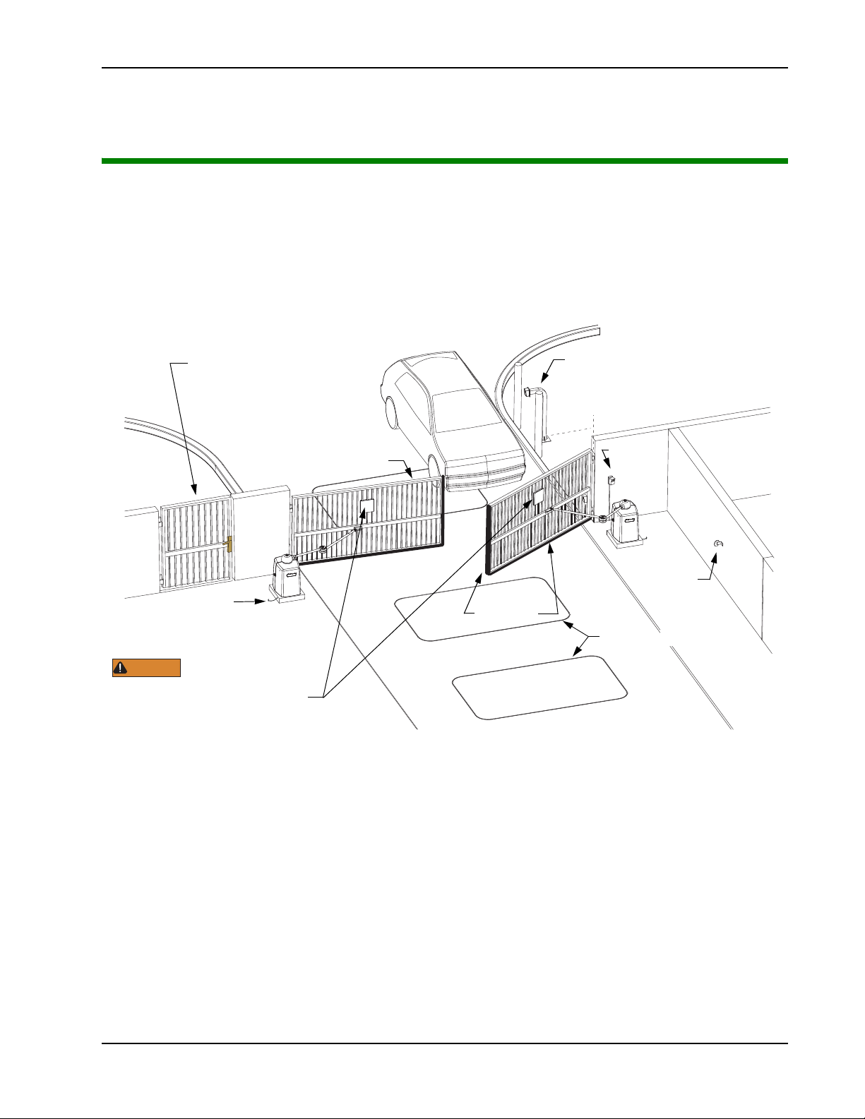
S
Secure Side
Public Side
C
L
Pedestrian gate
Make sure a separate walkthrough entrance is available and
its pedestrian path is clearly
designated.
Edge sensors
detectors
In-ground vehicle loop
Reflector for
photo eye
Photo eye
Keypad or Card Reader
Mount access control devices
at least 6ft (1.8m) beyond gate.
Earth ground
Attach WARNING Signs
Be sure to place the
WARNING signs on both
sides of the gate. For your records, take a
photograph of the completed installaon site.
WARNING
Wind Load Factors
Design gate panels to
accommodate for wind loads.
ITE
O
VERVIEW
& P
Site Overview & Planning
Installation
Chapter 1
LANNING
SwingSmart DC 20 SwingSmart DCS 20 Solar
Duty cycle: continuous Duty cycle: continuous
Power, single phase: Switch selectable Solar-powered
115 volts, 3 amps, 50/60 Hertz 24VDC, 100 cycles/day requires two 10 WATT
230 volts, 1.5 amps, 50/60 Hertz panels and a minimum of 5 solar hours/day.
Motor: ½ hp Motor: ½ hp
DC Batteries: Two 8Ah (50Ah optional) DC Batteries: Two 8Ah (50Ah optional)
Gate time to open/close: Gate time to open/close:
Approximately 10 to 15 seconds Approximately 10 to 15 seconds
Variable speed, open/close separately Variable speed, open/close separately
Gate weight: 1,300lbs @ 12ft leaf (590kg @ 4m leaf) Gate weight: 1,300lbs @ 12ft leaf (590kg @ 4m leaf)
Note: For more specifications, refer to the last page in this manual.
Revision E Installation 1-1
Figure 1-1.
Page 24
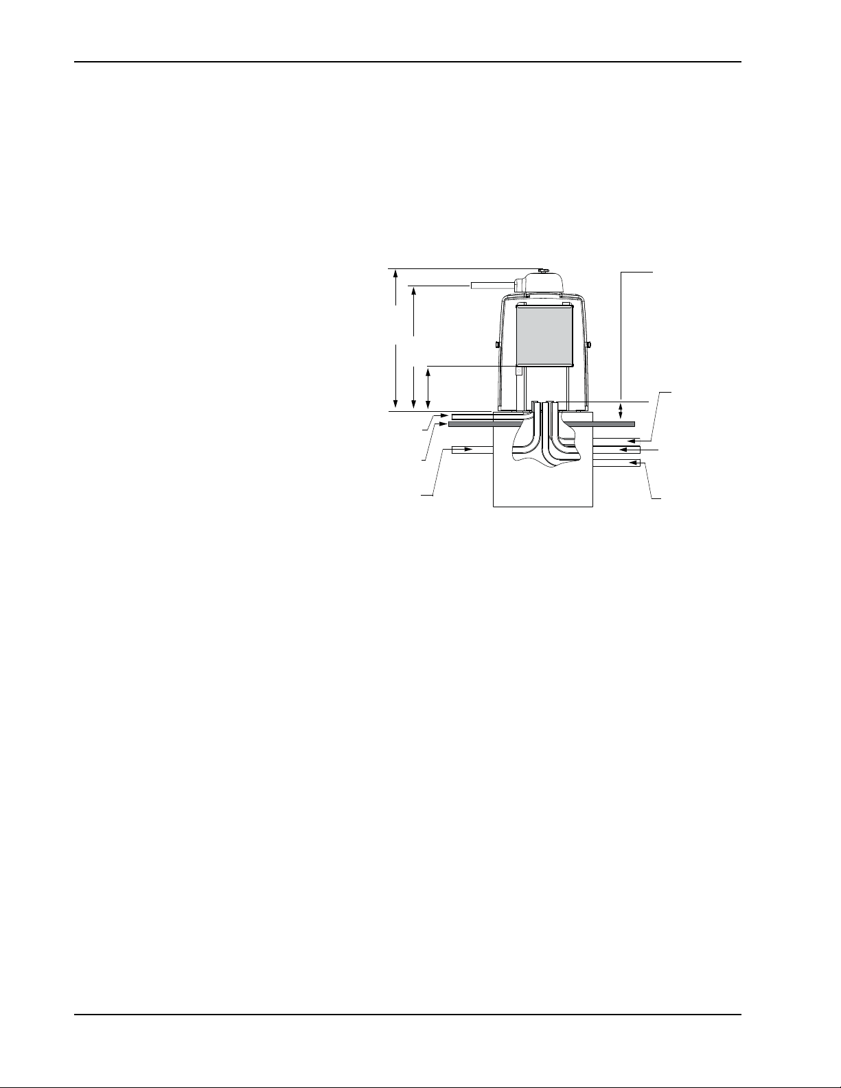
Pad Condition
Figure 1-2.
Low voltage/
Communication
wires
Master/slave
wires - optional
High voltage
30.2"
76.7cm
26.8"
(68cm)
Vehicle Loop
control wires
Earth ground
Ground level
9.6" (24cm)
control box
height
Stub out conduit
4-inches (102mm)
above ground
level
2-inch (51cm)
height above pad.
P
AD
C
ONDITION
Pouring the Concrete
1. Follow the local building codes to
identify the frost line and determine
the required depth of the concrete pad.
HySecurity recommends a minimum
16-inch (40.6cm) depth with a
minimum 2-inch (51cm) extension
above ground level. Refer to Figure 1-2
and Figure 1-3.
2. Before pouring the pad, consider
conduit placement so it fits within the
confines of the cutout in the
SwingSmart base plate as shown in
Figure 1-3. Run separate conduits for:
• high voltage wiring (115-230V
supply power) including
equipment ground
• low voltage wiring (12V and 24V
accessory power) including:
•vehicle loop control wiring
•master/slave connections
•earth ground (NEC/NFPA)
1-2 SwingSmart DC Installation and Refer ence Manual Revision E
Page 25
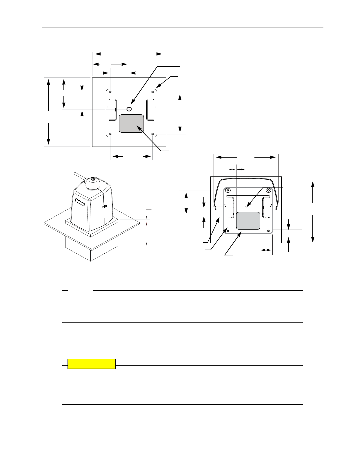
Pad Condition
NOTE
CAUTION
2.5"
7.6"
2.8"
1.8"
1.5"
3.5"
6" x 7"
(15.2cm x 17.7cm)
(8.9cm)
(3.8cm)
(4.6cm)
(19.3cm)
22" Cover
(56cm)
6.3cm
7.1cm
20" Cover
(50.8cm)
10.5" (26.7cm)
23" (58.4cm)
21" (53.3cm)
12" (30.5cm)
14" (35.6cm)
5.3"
5.7" (14.5cm)
minimum
10.5"
(13.4cm)
minimum
minimum
26.7cm
Pad Depth: 16" minimum
2" minimum
(51mm)
(41cm)
Output Shaft Center
Drill 4 holes for ½" x 3 ½" concrete anchors
6" x 7" conduit
area
Output
Shaft
Center
Cover area
Chassis base
14.5 x 16"
36.8 x 40.6cm
Conduit
area
Figure 1-3.
SwingSmart provides a 6 x 7-inch (15.2 x 17.7cm) cutout in its chassis base for conduit.
Refer to Figure 1-3. The design also provides a 9.6-inch (24.4cm) height between the control
box and chassis base for pulling and placement of wires.
3. Extend conduit height 2-inches (51mm) above the pad (4-inches/102mm above ground level). Make
sure the concrete forms are square with the gate and the pad is level. Refer to Figure 1-3 for minimum
pad dimensions.
Be sure to restrict conduit to the 6 x 7-inch (15.2 x 17.7cm) cutout in the chassis base if you
plan to use the extended battery backup kit. The area designed for the optional dual 50Ah batteries may be obstructed if conduit is routed elsewhere. Refer to
Backup Kit
.
Installing the Extended Battery
Revision E Installation 1-3
Page 26

Pad Condition
CAUTION
Using an Existing Pad
In many applications, SwingSmart may be a replacement operator for an existing gate system. Make sure the
pad is level and inspect the pad for:
• Compliance with local building codes.
• Appropriate distance from the gate. Refer to Figure 1-3.
• Appropriate dimensions for SwingSmart installation.
• Durability.
To use an existing pad, take the following steps:
1. Remove any existing equipment from the pad.
2. Measure the pad to ensure it is sized properly for SwingSmart.
3. Mark the center shaft location.
4. Follow the steps in
Consider positioning the operator so existing conduit exits through the cutout in the SwingSmart base plate. Cutting small holes in the base plate for pre-existing conduit is permissible,
but not recommended because it can impair the strength of the chassis and void the Limited
Warra nty.
Mounting the Operator
.
1-4 SwingSmart DC Installation and Refer ence Manual Revision E
Page 27
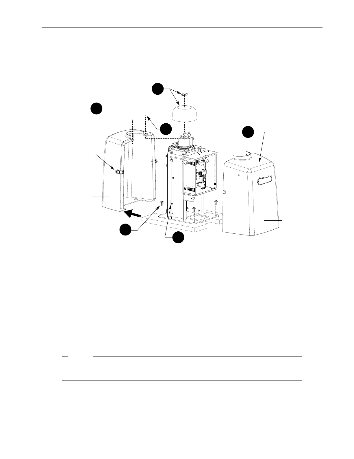
U
NOTE
1
2
3
5
6
4
Front cover
Rear cover
NPACKING THE
O
PERATOR
Unpacking the Operator
Figure 1-4.
Prepare the gate operator for installation. See Figure 1-4.
1. Remove the top cap by unscrewing the knob.
2. Unfasten the side cover latches.
3. Remove the front cover.
4. Use a Phillips-head screwdriver to remove the two screws that secure the top of the rear cover. Set the
screws aside.
5. Remove the two wing nuts that secure the rear cover to the base plate and set the rear cover aside. Set the
wing nuts aside.
Do not lose the Phillips-head screws or wing nuts as they are used to secure the rear cover when
the installation is complete.
6. Remove the four lag bolts and separate the operator from the shipping boards.
Revision E Installation 1-5
Page 28
Mounting the Operator
Photo Eye
Photo Eye
For short gates up to 10 feet (3m):
If X = 10.5",
Set Y dimension at 14, 18, or 20".
(35.6, 45.7, or 50.8cm)
For medium gates up to 13 feet (3.9m):
If X = 12",
Set Y dimension at 22, 24, or 28".
(55.9, 61, or 71cm)
For long gates up to 20 feet (6.1m):
If X = 15",
Set Y dimension at 30, 35, or 40".
(76, 89, or 102cm)
Hinge Center
Output Shaft Center
X
Y
Potential entrapment area.
Minimum 16
"
(40.6cm) clearance
required. If less than 16
"
, install a
photo-eye or edge sensor.
Figure 1-6.
Concrete
anchor
Fasteners
Concrete
anchors
Base plate
Concrete
pad
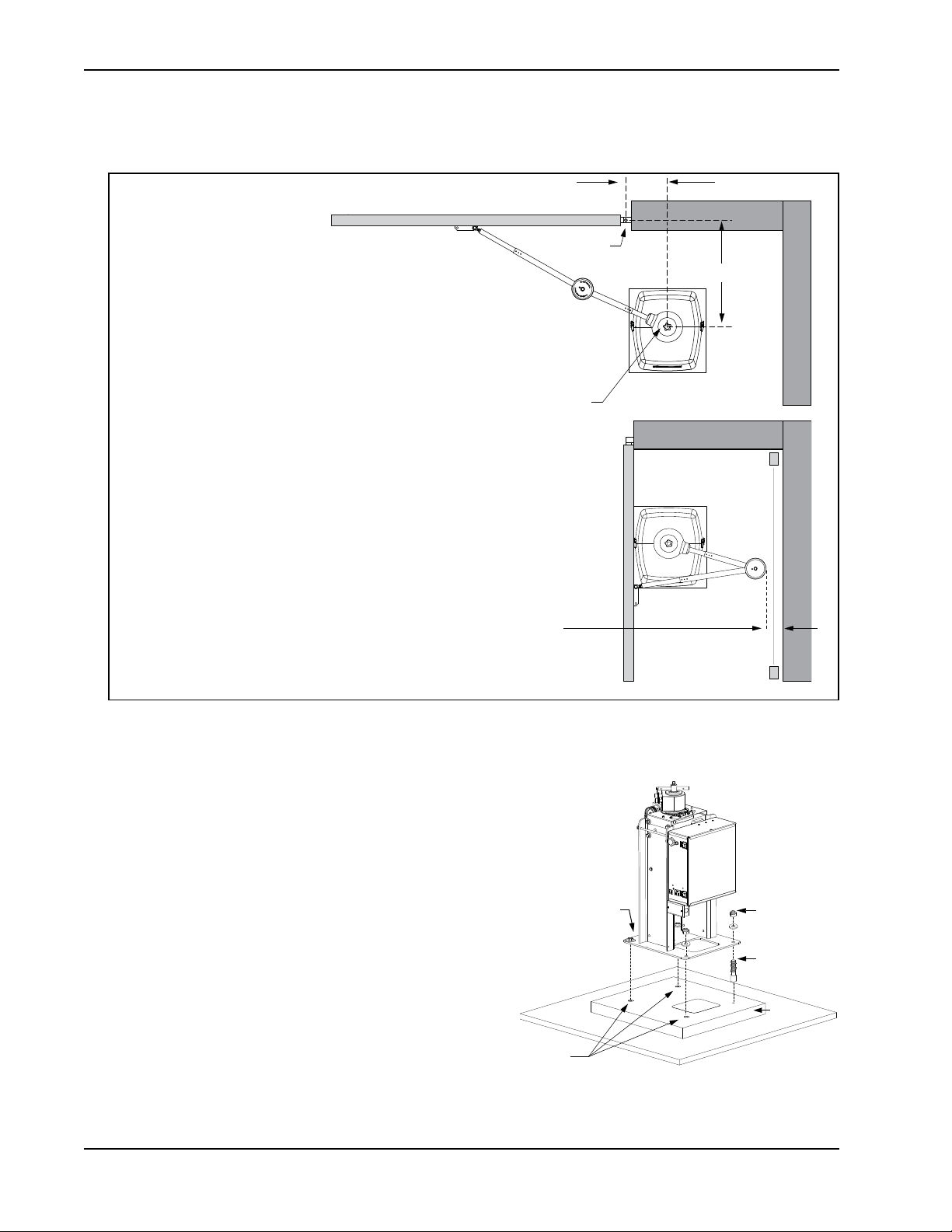
M
OUNTING THE
O
PERATOR
Install the operator, by taking the following steps:
1. Assess any limitations in the surrounding area such as
curbs, walls, or bushes.
2. Before placing the operator on the pad, measure and
mark the output shaft center on the concrete pad by
selecting the X and Y dimensions. Refer to Figure 1-3
and Figure 1-5.
3. Set the operator base on the concrete pad and use it as a
template. Position the operator base so the center mark
on the pad aligns with the small hole in the base plate.
Mark the fastener and conduit cutouts. Remove the
operator from the concrete pad and drill the holes for
the concrete anchors.
4. Mount the operator with four ½ x 3½-inch concrete
anchors as shown in Figure 1-6.
1-6 SwingSmart DC Installation and Refer ence Manual Revision E
Figure 1-5.
Page 29
G
CAUTION
!
Short Gate Installation:
For gates up to 10 feet (3 meters)
X
Y
Xg
14" 23.5"
10.5"
18" 27.5"
Medium Gate Installation:
For gates up to 13 feet (4 meters)
Long Gate Installation:
For gates up to 20 feet (6 meters)
Custom Gate Installation:
X
Y
Xg
X + Y - 1
36cm
27cm
60cm
46cm
70cm
20" 29.5"
51cm
75cm
X
Y
Xg
22" 33"
12"
24" 35"
56cm
31cm
84cm
61cm
89cm
28" 39"
71cm
99cm
X
Y
Xg
30" 44"
15"
35" 49"
76cm
38cm
112 cm
89cm
124cm
40" 54"
101cm
137cm
Operator Center
Photo eye
Horizontal
cross member
Hinge Center
X
Y
Xg
ATE
B
RACKET AND
L
INKAGE
Installing the Gate Bracket
Gate Bracket and Linkage Arms
A
RMS
1. Secure the gate to prevent movement.
2. Determine the proper position of the gate bracket. Use the chart for reference.
3. Measure and position the gate bracket so it is level with the arm on the operator. Clamp the gate bracket to
Revision E Installation 1-7
Figure 1-7.
If vertical bars make up the gate design, be sure to install a horizontal cross member to provide
the necessary support to the gate arm. Do not mount the bracket to a small number of vertical
pickets. Pickets will bend in the event of a gate strike.
Hint
: Determine if you have a short, medium, or long gate. If the X and Y dimensions in the chart are the
same as your install, set the gate bracket at the Xg dimension. If your install does not fit to the chart specs,
use the Custom Gate Installation formula to determine the proper gate bracket placement.
the horizontal cross member.
Page 30
Gate Bracket and Linkage Arms
NOTE
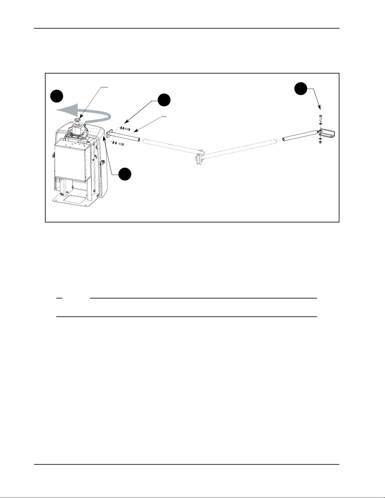
2
1
4
3
Taper handle
Stub arm
Attaching the Stub Arms
Figure 1-8.
1. Attach the swivel eye bolt to the gate bracket using the fasteners provided.
2. Remove the fasteners from the taper clamp assembly.
3. Align the stub arm and secure it to the taper clamp assembly using the fasteners removed in step 2.
4. Pull the taper handle to lengthen it. Adjust the handle so the ball detent fits into its cutout and secures the
handle length. Turn the handle counterclockwise to loosen the taper clamp. Figure 1-8.
Do not retighten the taper clamp. It needs to remain loose for manual gate adjustments.
1-8 SwingSmart DC Installation and Refer ence Manual Revision E
Page 31

Installing the Linkage Arms
NOTE
X
Xg
Hinge Center
Y
Short Gate Installation:
For gates up to 10 feet (3 meters)
X
Y
Xg
14" 23.5"
10.5"
18" 27.5"
Medium Gate Installation:
For gates up to 13 feet (4 meters)
36cm
27cm
60cm
46cm
70cm
20" 29.5"
51cm
75cm
X
Y
Xg
22" 33"
12"
24" 35"
56cm
31cm
84cm
61cm
89cm
28" 39"
71cm
99cm
A
B
15.5" 21.5"
17.5" 24.5"
39cm
55cm
44cm
62cm
19" 26"
48cm
66cm
A
B
21" 29"
22" 30.5"
53cm
74cm
56cm
78cm
24" 33.5"
61cm
85cm
Long Gate Installation:
For gates up to 20 feet (6 meters)
Custom Gate Installation:
X
Y
Xg
X + Y - 1
X
Y
Xg
30" 44"
15"
35" 49"
76cm
38cm
112 cm
89cm
124cm
40" 54"
102cm
137cm
A
B
0.87 * Xg
0.63 * Xg
A
B
28"
38.5"
30.5"
42.5"
71cm
98cm
78cm
108cm
33.5"
46.5"
85cm
118 cm
Space for custom
calculations:
Operator Center
A
B
Linkage arms
NOTE: Maximum measurement for A = 38 inches (97cm)
Maximum measurement for B = 47.5 inches (121cm)
Keep the elbow joint at a slight
angle to avoid hyperextension and
allow compensation for light gate
strikes without severe damage to the
gate operator.
NOTE: At secure sites, straightening the
arm lowers the chance of someone
manually pushing the gate open.
SwingSmart operators ship with separately packaged linkage arms. The linkage arms have a
universal elbow joint and can be used on either an operator with right handing or left-handing
by simply flipping the linkage arms. The excess on the over travel stop is then sawn off to
accommodate for the top and bottom elbow joint covers.
Gate Bracket and Linkage Arms
1. Slide the linkage tubes on the appropriate stub arms
and use the tapped holes for adjustment purposes.
Tighten the hex-head bolts to hold the arms in place.
Refer to Figure 1-10.
2. Verify the A and B dimensions on the arm linkage
tubes. For short gate applications, the linkage arms
must be cut to achieve the required lengths. See
Figure 1-9. If your operator position does not fit the
chart specs, use the Custom Gate Installation formula
to determine the proper length.
Revision E Installation 1-9
Figure 1-9.
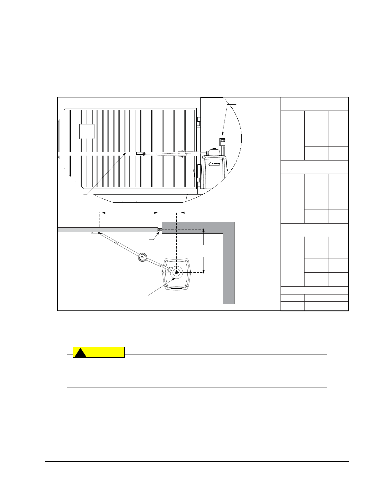
Operator Placement & Gate Arm Geometry
for 100° through 130° opening
Y
° of Swing
100°
110°
120°
130°
X
24" 36"
20"
51cm
61cm
26"
24"
66cm
61cm
32"
20"
81cm
51cm
38"
18"
97cm
46cm
NOTE: Maximum A = 38" (97cm) Maximum B = 47.5" (121cm)
Xg
91cm
39"
99cm
41"
104cm
44"
112cm
A
24"
61cm
28"
71cm
31.5"
80cm
36"
91cm
B
36"
91cm
40.5"
103cm
44"
112cm
47.5"
121cm
Page 32

Gate Bracket and Linkage Arms
NOTE
Note: The elbow pivot bolt must be parallel with the vertical axis of the operator. If the pivot
bolt is not vertical, binding of the arm assembly may occur during operation.
Elbow
Pivot bolt must run
parallel with the vertical
axis of the operator.
Tapped hole used for
linkage arm adjustments.
Set screw
Use the set screw to finetune the vertical orientation
of the pivot bolt and prevent
the arm from locking.
Over-extension stop
Figure 1-11.
CORRECT
alignment with
gate in the open
position.
INCORRECT
alignment.
Linkage arm (B)
needs to be
shortened.
B
A
B + 3"
B + 7.6cm
Figure 1-10.
The linkage tubes used for the arm can be drilled and bolted or welded together. Do the finishing
work AFTER the arm and gate adjustments are complete. See
Completing Gate Arm Installation
3. To verify appropriate arm length, manually push the gate to the
full open and close positions. Maximum security is obtained
when the elbow on the linkage arms is slightly bent with the gate
closed and at an approximate 90° angle with the gate in the open
position. See Figure 1-11. Refer to NOTE on page 1-11.
4. During the open and close process:
• Verify all pivot joints rotate smoothly without binding. At
the full open position, linkage arms must not scissor or
bind.
• Make sure the longer arm (B) does not collide with the top
cap cover.
• See Figure 1-10 and make adjustments to arm lengths by:
• loosening the set screws
• telescoping the arms
• retightening the set screws
.
1-10 SwingSmart DC Ins tallation and Reference Manual Revision E
Page 33

Adjusting the Limit Switches
NOTE
Left hand OPEN
Right hand OPEN
PUBLIC SIDE
SECURE SIDE
Limit switches
Figure 1-13.
Loosen
screws
Limit plate
Limit cam
Limit cam
Figure 1-12.
Gate Bracket and Linkage Arms
1. Determine whether the gate operator is a right-hand operator or left-hand operator. See Figure 1-12. Stand
on the secure side of the gate. If the gate opens to the right, it is a right-hand operator.
For a right-hand operator, the OPEN switch is the left limit switch as shown in Figure 1-13
The opposite occurs in a left-hand operator; the OPEN switch becomes the right limit switch.
2. To adjust the limit cams, use a Phillips-head screwdriver
and loosen the fastener that secures each limit cam to the
limit plate.
3. Manually, open and close the gate. Move the limit cams
so they trip the appropriate limit switch at the full OPEN
and full CLOSE positions.
4. Secure the limit cams by retightening the two Phillips-
head screws.
A fin on the limit plate fits into the taper clamp. This feature
ensures the limits always track the gate arm position even if
the gate is struck and the taper clamp slips.
Note:When reassembling the taper clamp, make sure the limit
plate fin is seated into the slot on the taper clamp.
Revision E Installation 1-11
Page 34

Gate Bracket and Linkage Arms
CAUTION
To weld the linkage arms:
Weld a 1/8-inch fillet
around the tubing joint.
To use fasteners: Drill holes with a 17/64-inch drill bit and connect
arms with 1/4 - 20 UNC fasteners.
1/8"
1/8"
DRILL & BOLT (2x)
WELD
1A
1B
1A
1B
Completing Gate Arm Installation
1. To determine whether you should drill & bolt or weld the linkage arms, you should take into consideration
2. Paint exposed areas to prevent rusting.
1-12 SwingSmart DC Ins tallation and Reference Manual Revision E
Figure 1-14.
site planning and future impact to gate arm installation. Check whether fire bans exist at your site. Fire bans
do not permit outdoor welding.
For sites where incident of gate strikes are high, HySecurity recommends setting the elbow with
a slight offset at the full close position. Use the supplied set screw to prevent the arm from locking. The intent of the offset is that, upon gate strike, the elbow will bend and the taper clamp
will slip, minimizing damage to the gearbox and operator. Be aware if the elbow is set straight
and a gate strike does occur, the full force of the impact will be transferred through the linkage
arms and into the gearbox causing possible damage to the gearbox and operator.
DRILL & BOLT: If you plan to use fasteners, drill holes through the linkage arms. Refer to Figure 1-14.
WELD: If you plan to weld the linkage arms, weld a 1/8-inch fillet around the tubing joint. Only weld at
sites where outdoor welding is permitted.
Page 35

Gate Bracket and Linkage Arms
NOTE
CAUTION
!
Top and bottom covers need to be
evenly aligned. Gap should be less
than ¼-inch.
Cover
fastener
Cover
fastener
Bottom cover
Top cover
Elbow joint
2
Over-extension stop
Cut excess
Figure 1-15.
The two elbow joint cover fasteners are shipped with the covers.
3. Saw the excess from the over-extension stop. Be careful not to cut the linkage arms or pivot bolt fasteners.
4. Place the covers over the elbow joint.
5. Align the mounting holes and cutouts in the covers with the gate arms.
6. Make sure the gap between the top and bottom covers is evenly aligned. See Figure 1-15.
7. Insert the two fasteners and secure the covers.
It is critical that you install the elbow joint covers to comply with UL325 Safety Standards. The
elbow joint is considered a pinch point and serious injury may occur if the covers are not
secured properly to the gate arms.
Revision E Installation 1-13
Page 36

Gate Bracket and Linkage Arms
NOTE
CAUTION
Spherical rod end
Gate attachment
bracket
Cover and fastener
Elbow joint
Spherical rod end
Pivot bolt
Articulating Arm Option
The articulating arm assembly uses a spherical rod end at the elbow and at the bracket mount. Situations where
you might use this option include:
• The operator pad or gate is not level. The spherical rod ends on the articulating arm forgive minor
discrepancies where the hardware may not be perfectly plumb.
• The gate arm is not horizontal.
By ordering the articulating arm assembly for use in these situations, the binding stress between the operator
and gate hardware is reduced.
Although some sites necessitate fastening a gate arm to the gate at an angle, HySecurity does
not recommend it. The preferred method is an installation where the gate arm remains horizontal throughout gate travel.
When installing an articulating arm assembly, be sure to take into account the following guidelines:
• A gate must be neutrally balanced. To comply with ASTM F2200 General Requirements, a gate must be
designed, constructed and installed in such a way that its movement is not initiated by gravity when the
gate operator is disconnected or loses power.
• The over-extension stop on the standard HySecurity gate arm does not exist on the articulating arm. To
avoid hyperextension, mount the arm so a slight bend at the elbow joint is maintained in the gate closed
position. This slight bend may prevent damage to the operator during a gate strike because it allows the
elbow to bend properly and permits the taper clutch to slip thereby reducing the impact to the operator.
• Due to the flexibility in the elbow joint, only one pinch protection cover is used.
If the gate arm is mounted at a slight angle, test the operation of the gate several times. Be sure
to check for clearance issues. If possible pinch points exist, make sure to adjust the gate arm and
eliminate any clearance issues or pinch points.
1-14 SwingSmart DC Ins tallation and Reference Manual Revision E
Page 37

Setting the Taper Clamp
NOTE
Tig hte n
Retract
45° angle
Simulate a gate strike
with ~ 100 lbs. of
force.
Loosen
Tap er
handle
Gate Bracket and Linkage Arms
Figure 1-16.
Setting the taper clamp with the gate closed impedes traffic flow. If vehicles need to pass
through the gate area, delay setting the taper clamp until after the operator has been configured
to run. Refer to Chapter 3,
Configuring the Setup Menu
.
The taper clamp is made of two pieces: a cone-shaped hub fits into a taper clamp assembly. The more you turn
the taper handle clockwise the harder it becomes to slip the clutch. In certain situations, such as secure military
facilities, consider straightening the gate arm instead of over-tightening the taper clamp. Refer to
Gate Arm at Secure Facilities
.
Locking the
1. To loosen and release the taper clamp, extend the taper handle and turn the handle counterclockwise. See
Figure 1-16.
2. Manually, swing the gate half way between the open and closed position (approximate 45° angle).
3. To tighten the assembly, turn the taper clamp handle clockwise in 1/8-inch (3.2mm) increments. A large
amount of torque is not required in order to obtain a tight clutch setting.
4. Push the gate end with approximately 100 pounds of force to simulate a gate strike. If the taper clamp
slips, use the taper handle to further tighten the assembly.
5. Continue to adjust the taper clamp until no slippage occurs.
6. Retract and center the taper clamp handle.
Revision E Installation 1-15
Page 38

Gate Bracket and Linkage Arms
NOTE
Locking the Gate Arm at Secure Facilities
The purpose in leaving the gate arm with a slight bend in it (i.e. turning the set screw to offset the over travel
stop) is to lessen the transference of energy along the gate arm during gate strikes. With the gate arm bent at a
slight angle, it can absorb more of the impact and possibly cause less damage to the gear box in the
SwingSmartDC operator.
At facilities that require higher security, you may want to consider straightening the gate arm to “lock” it in
place so pushing the gate open becomes much more difficult.
Some aspects to consider, if you want to limit opportunities to force the gate open:
• Turn ON the Force Open Alert in the User Menu by setting the menu item FA to 1. When set to 1 and the
gate is forced open, a 3-second buzzer alerts the surrounding area that the gate is being forced off its closed
limits. The gate operator attempts to close the gate, but if the gate does not begin to fully close within
4 seconds, the motor turns off and the buzzer continues for another 30 seconds. ALERT 1 - FORCED
OPEN appears on the display. (An OPEN or CLOSE command clears the alert and resets the display.)
• Fully straighten the gate arm, so it is in a straight “locked” position. Throughout the instructions found in
this manual, it states that a bend in the gate arm is critical to offset the damage that may be inflicted to the
gate operator during a gate strike. If the purpose is to use excessive measures to keep the gate closed,
consider fully straightening the gate arm during installation. Straightening the gate arm after installation
will require loosening the set screw and moving the gate bracket or other gate hardware.
• Lock the movement of the gate using an external method, such as a locking chain.
Keep the taper clamp tight as explained in the procedures on the previous page. Do not overtighten the taper clamp. Overtightening the taper clamp may cause excessive wear to the clutch
mechanism or damage to the taper clamp causing it to stick during normal gate operation.
1-16 SwingSmart DC Ins tallation and Reference Manual Revision E
Page 39

Installing the Earth Ground
DANGER
!
NOTE
Power
Chapter 2
I
NSTALLING THE
An earth ground refers to the grounding rod and accompanying equipment ground which need to be installed
to safeguard against potential electrical shock and damage to personnel and equipment.
The potential for lightning discharge exists with all gates, fences and gate operators. National Electric Code (NEC) requires a separate earth ground in addition to the required equipment ground.
HySecurity recommends grounding the operator with a separate earth ground connected to a ground rod to
assure proper operation and shield it against electromagnetism and other electrical signals that may cause
erratic operation with or damage to the Smart DC Controller.
E
ARTH
G
ROUND
If you do not ground the operator with a separate earth ground rod, you risk voiding the
Limited Warranty.
For earth grounding requirements, refer to the National Fire Protection Association (NFPA) 780 -
the Installation of Lightning Protection Systems
• The ground rod is a solid copper rod: minimum requirements: ⅝
length.
• The ground rod is driven into the earth (refer to local codes for proper depth requirements).
• The ground rod is electrically bonded to the chassis with a single length of un-spliced 6AWG copper wire
less than 3 feet (91cm) long.
• Local jurisdictions may impose additional requirements above the NEC and NFPA 780. Consult the local
codes and regulations regarding requirements in your area.
. Highlights of the standard include.
"
(16mm) diameter and 10 feet (3m) in
Standard for
Revision E Power 2-1
Page 40

Installing the Earth Ground
Lug nut
Consult local
codes for
proper depth.
3 ft
Run ground wire
through concrete
base.
Figure 2-1.
Take the following steps to comply with NEC and NFPA 780 standards:
1. Install a grounding rod per local building codes. See Figure 2-1.
2. Attach a large earth ground wire (6AWG) from the grounding rod to
the lug nut on the base of the chassis.
•
New site
: Run the 6AWG wire through the concrete base and into
the cutout on the chassis base.
•
Existing site
: Run the 6AWG wire beneath the rear cover. Make
sure the covers align and side latches lock properly.
Properly grounding the gate operator is critical to gate operator
performance and the life of its electrical components. Use sufficient wire
size during installation. Refer to
230VAC Power
.
Wiring 115VAC Power
or
Wiring 208/
2-2 SwingSmart DC Installation and Refer ence Manual Revision E
Page 41

W
DANGER
!
CAUTION
!
WARNING
Place the power switches in the
OFF position.
Service outlet
115 VAC wires for the service outlet.
Junction box cover and label
Voltage selector switch is
factory set to 115V.
If power input is 208/230V,
move the switch so 230V
appears and change the
label on the junction
box cover.
The service outlet is wired for 115VAC. To
use the 115VAC service outlet on a 208/
230VAC installation, the electrician needs
to run an extra neutral wire to the operator
from the power source and wire the service
outlet per code.
High voltage
protection cover.
NOTE: For 208VAC a separate transformer option
kit may need to be ordered.
Wiring AC P ower
IRING
AC P
OWER
Turn off AC power at the source (circuit breaker panel) before accessing the wires in the SwingSmart junction box. Follow facility Lock Out/Tag Out procedures. Make sure both the DC and AC
power switches, on the side of the SwingSmart control box are in the off position. See Figure 2-2.
Wiring of gate operators must conform to the NEC standards and comply with all local codes.
If you plan to connect to 208/230VAC power, read the WARNING in Figure 2-2. The voltage
selector switch on the AC Power board must be moved to the 230V position or damage to the
operator will occur and void the Limited Warranty.
Revision E Power 2-3
Figure 2-2.
Page 42

Wiring AC Power
NOTE
CAUTION
!
Wiring 115VAC Power
For standard 115VAC power connection:
• Verify AC power supply wires and low voltage (12V & 24V accessory power wires) run through two
separate conduits. The higher voltage from the AC power supply may cause interference and anomalies in
SwingSmart operation if the high and low voltage wires are routed through the same conduit.
• Maximum gate operator current draw is 3 Amps on a dedicated 115VAC circuit (20A dedicated circuit is
recommended).
• Make sure proper wiring is being used. The following table shows the maximum allowable wire run from
the power source to the operator for various wire sizes.
Table 2-1. Wire Gauge versus Run
AC Power 14 gauge wire 12 gauge wire 10 gauge wire
One operator 115V 730 ft (223 m) 1200 ft (366 m) 1900 ft (579 m)
Two operators 115V 460 ft (140 m) 750 ft (228 m) 1160 ft (354 m)
Note:Table 2-1 assumes a dedicated circuit with an accessory power load up to 2A.
Additional loads require that the wire size be increased or the distance of the run be decreased.
To connect to 115VAC power, take the following steps:
1. Make sure the AC power is turned off at its source and the DC and AC power switches on the operator are
in the off position.
2. Access the input power wires and service outlet wires by removing the two Phillips-head screws that secure
the high voltage junction box cover. See Figure 2-2.
The service outlet wires are solid copper and are labeled and bound together to keep them separate from the AC power switch wires.
3. Wire nut or crimp bond the power supply wires to the black and white lead wires coming from the AC
power switch (no label).
4. Wire nut or crimp bond the equipment ground wire to the green ground wire in the junction box.
5. To activate the 115VAC service outlet, include the black and white outlet lead wires and the green ground
wire in the connections made above.
6. Neatly organize all wire connections and replace the high voltage junction box cover. Secure it with the two
Phillips-head screws.
Wiring 208/230VAC Power
All SwingSmart operators are shipped from the factory as 115VAC units. When connecting to
208/230VAC power, the voltage selector switch on the AC power board must be moved to the
230V position or damage to the operator will occur and void the Limited Warranty.
2-4 SwingSmart DC Installation and Refer ence Manual Revision E
Page 43

Wiring AC P ower
DANGER
!
Figure 2-3.
Voltage selector switch
set to 230V.
For the 208/230VAC power connection:
• Verify AC power supply wires and low voltage (12V & 24V accessory power wires) run through two
separate conduits as discussed in
Wiring 115VAC Power
.
• Maximum gate operator current draw is 1.5 Amps on a dedicated 208/230VAC circuit (20A dedicated circuit
is recommended).
• Make sure proper wiring is being used. Refer to the following table:
Table 2-2. Wire Gauge versus Run for 208/230VAC
AC Power 14 gauge wire 12 gauge wire 10 gauge wire
One operator 208/230V 2095 ft (639 m) 3350 ft (1021 m) 5300 ft (1615 m)
Two operators 208/230V 1465 ft (446 m) 2350 ft (716 m) 3750 ft (1143 m)
Note:Table 2-2 assumes a dedicated circuit. Additional loads require that the wire size be
increased or the distance of the run be decreased.
To connect to 208/230VAC power, take the
following steps:
1. Make sure the AC power is turned off at its
source and the DC and AC power switches
on the operator are in the off position.
2. Remove the High Voltage Protection cover
by unscrewing the two Phillips-head screws
that secure it.
3. Toggle the voltage selector switch from 115V
to 230V. Replace the High Voltage cover and
30V
secure it. See Figure 2-3.
4. Access the input power wires by removing the
two Phillips-head screws that secure the High
Voltage Junction Box Cover. See Figure 2-2.
5. Wire nut or crimp bond the power supply
wires to the black, red, and white lead wires
coming from the AC power switch (no label).
6. Wire nut or crimp bond the equipment
ground wire to the green ground wire in the
junction box.
To use the service outlet with 208/230VAC, a separate neutral wire (white) must be run from the
power source. Make sure the incoming power wires are sized appropriately to support the load
expected on the service outlet. Follow guidelines per the National Electrical Code Article 250.
7. Neatly organize all wire connections and secure the Junction Box Cover with the two Phillips-head screws.
8. Place the 208V or 230V 1Ø label on the Junction Box Cover over the 115V 1Ø label.
Revision E Power 2-5
Page 44

Connecting DC Power
NOTE
Figure 2-4.
Red spade
connector
C
ONNECTING
To connect the DC power:
1. Turn off the DC and AC
power switches.
2. Slide the plastic cover off
the control box.
3. Attach the red spade
connector to the battery
terminal on the DC power
switch. See Figure 2-4.
Note: For extended battery
backup installation, refer to the
Installing the Extended Battery
Backup Kit instructions.
DC P
OWER
U
SING
S
OLAR
HySecurity offers a solar version of the SwingSmart operator: SwingSmart DCS20. The solar model has
different internal wiring and includes software programmed for solar use. The Smart DC Controller has a
built-in charger which allows a 24V solar panel (or two 12V panels) a direct connection to the SwingSmart
operator with no additional electronic devices required.
To plan a solar-powered site, read through this entire section. Keep in mind that the SwingSmart DCS 20
operator does not have the following components:
• Transformer
•AC power supply board
• AC service outlet
• Various wiring adaptations that are standard in a SwingSmart DC 20 operator
A
P
OWERED
Solar panels are NOT included in the purchase of the SwingSmart DCS 20 Solar operator.
Also, adapting a standard SwingSmart DC operator to a solar application is not recommended.
For ease of installation and proper functionality, be sure to order a SwingSmart DCS 20 for a
solar-powered site.
O
PERATOR
2-6 SwingSmart DC Installation and Refer ence Manual Revision E
Page 45

Using A Solar Powered Operator
NOTE
NOTE
NOTE
Design Requirements & Considerations
Two standard 8Ah batteries are supplied with SwingSmart DCS 20 and nominally support up to 100 cycles per
day based on the following:
• Battery storage capacity based on 5 solar hours per day. See Figure 2-7.
• 20WATT solar panel system (minimum requirement). See Figure 2-5.
• A gate weight of 750lbs (340kg) and gate length of 12ft (3.7m)
• Connection to two HY-5A and one multi-code radio receiver. Note that if connected properly, photo eyes
are not considered in the power load because the Smart DC Controller only powers the photo eyes when
the motor engages. Refer to
The available 50Ah battery option supports more peripheral connections because of its
higher storage capacity. A higher energy storage capacity provides a higher sustained current
draw. If the solar operator will be opening and closing more often at night or in low solar hour
conditions, consider using the 50Ah option and two 20WATT panels (for a total capacity of 40
WATTS ).
Installing Photoelectric Sensors For Secondary Entrapment Protection Only
.
The design of the solar-powered site is important in maintaining the highest gate cycle capacity and extending
the life of the batteries. The construction of a solar-powered gate and its cycle capacity is significantly affected
by the following:
• Energy demand of the peripheral devices. The more energy efficient the device the less power draw occurs
to the batteries.
• Solar hours at the site. “Solar hours” relate to the amount of energy delivered by the sun and absorbed by
the solar panels. It is NOT the same as the number of daylight hours available at the site. See Figure 2-8.
• Design considerations must use calculations that are figured for the darkest months of the year (typically
December/January). Higher wattage panels may be required.
• Impediments to the sun’s rays reaching the solar panels. Elements such as, shade, improper alignment, or
dirty panels will reduce the amount of power available.
Solar panels must not be shaded (not even partially) or the output power will be significantly
reduced. Panels must be kept clean as small areas of sunlight blockage cause a large reduction in
output power. Alignment is also critical because the rated wattage output is based on the solar
panels being mounted perpendicular to the angle of the sun’s rays midday on winter solstice
(December 21st).
• Extreme temperatures affect battery life. Keep the batteries away from temperatures above 90°F (32°C).
See
Important Considerations for DC-powered Operators
• Good gate hardware and smooth, unobstructed gate travel lowers the operator’s power draw and serves to
extend battery life.
.
Any solar systems that are designed close to the minimum margins will stress and shorten the
battery life and risk unreliable operation, especially in periods of inclement weather.
Revision E Power 2-7
Page 46

Using A Solar Powered Operator
NOTE
Figure 2-5. Solar Panels and Wiring Connections
Green wires
Red wires
Black wires
Connecting the SwingSmart DCS 20 t o Solar Power
Panels
1. Use 14 gauge wire or larger to connect the solar panel(s) within 100ft (30.5m) of the operator. Check
NEC and local regulations if other distances apply.
2. Use one 24VDC solar panel or two 12VDC solar panels in series with a total capacity of at least 20W.
Mount them according to the manufacturer's installation instructions.
3. Make sure both DC power switches on the SwingSmart control box are in the OFF position, and then
remove the two Phillips head screws that secure the 24VDC cover to the junction box.
4. Wire nut or crimp bond the solar panel wires to the black and red input wires. See Figure 2-5.
5. Wire nut or crimp bond the equipment ground wire to the green ground wire in the junction box.
Minimum
10W Panel
12V
Two 12V panels in
series connect to gate operator
or
One 24V panel connects
to gate operator
For extended battery backup installation instructions, refer to
Backup Kit
.
Minimum
10W Panel
12V
Minimum
20W Panel
24V
Installing the Extended Battery
6. Slide the plastic cover off the control box and attach the red spade connector to the battery terminal on the
upper DC power switch. See Figure 2-6.
7. Turn both DC power switches ON and program the Smart DC Controller. See
Menu
.
2-8 SwingSmart DC Installation and Refer ence Manual Revision E
Configuring the Setup
Page 47

Figure 2-6. SwingSmart DCS 20 Control Box
Control Box
DC Battery & Motor
switch (OFF)
DC Solar Panel
switch (OFF)
Input & ground wires
Red spade
connector
Using A Solar Powered Operator
.
Revision E Power 2-9
Page 48

Using A Solar Powered Operator
CAUTION
COM
COM
COM
COM
COM
COM
COM
COM
STOP
OPEN
RADIO
CLOSE
OPEN
OPEN
PARTIAL
EYE
OPEN
EYE
CLOSE
EXIT
LOOP
BLOCK
EXIT
IN OBS
LOOP
OUT OBS
LOOP
CENTER
LOOP
EDGE
EYE
COM
+ 24 V
EMERG
OPEN
SHOW
LEDs
R
AD
IO O
PTI
ON
S
E
D
GE
+
2
4V
OPE
N
C
O
M
D
U
AL GA
T
E
C
O
M
B
A
U
SER2
C
O
M
N
O
DC
COM MON
TERMINALS
HY-5A
FREE EXIT
HY-5A
INSIDE LOOP
HY-5A
OUTSIDE LOOP
HY-5A
CENTER LOOP
RS-485
COMMUNICATION
USB PORT
USER RELAY 1
Electromechanical
USER RELAY 2
Solid state
USER 1
24VDC
1 AMP
MAX
24VAC
1 AMP
MAX
12VDC
1 AMP
MAX
LOOP
24VDC
1 AMP
MAX
24VAC
1 AMP
MAX
12VDC
1 AMP
MAX
24VDC
MAX
1 AMP
MAX
Figure 2-7.
Two power supplies are available for peripheral
connections:
24VDC and 12VDC
NOTE: The 24VDC power supply has four terminals
that can be used in any combination to draw the
available 1A maximum. The 12VDC has two terminals.
Example of Peripheral Amp Draw
0.015A = 3 HY-5A vehicle detectors
0.029A = 1 multi-code radio receiver
0.000A = 4 photo eyes (see NOTE).
0.044A = Total amps needed for site design purposes
Photo EYE COM
terminal
Photo eye 24VDC
NOTE: Photo eyes
connected to these terminals
receive power when the motor engages
which means the draw on the battery is
minimal.
Connecting Peripherals to Solar Operators
The 24VAC power supply shown in Figure 2-7 is not to be used for peripheral connections
because the 24VAC terminals are directly connected to the solar panel inputs. Any peripherals
attached to the 24VAC terminals could be severely damaged due to varying voltage levels.
To connect any peripheral devices to a solar operator, use the 24VDC or 12VDC terminals. Because a solar
operator gets its energy from the sun and stores the energy produced by the solar panels in batteries that are
constantly discharging, it is important to use peripheral devices that draw and consume as little power as
possible.
2-10 SwingSmart DC Ins tallation and Reference Manual Revision E
24
Page 49

Using A Solar Powered Operator
NOTE
Four Week Average, December 7 - January 4
2.5
2.5
3.0
4.0
3.0
2.0
4.0
5.0
5.0
0.0
For up-to-date
solar isolaon maps, refer to
hp://www.nrel.gov/gis/solar.html
1.7
Arc Circle
3.5
3.5
4.0
This solar isolaon map recreated courtesy DOE.
5.0 100 (20W panel)
4.5 60 (20W panel)
4.0 48 (20W panel)
3.5 34 (20W panel)
3.0 20 (20W panel)
Solar Gate cycles/day
hrs/day using 8Ah baeries
2.5 6 (20W panel)
Map Legend
The chart is based on a 20 Watt (24VDC) solar panel system with
SwingSmart powering a 12 foot (3.6m), 750lbs (340kg) gate with the
following peripherals attached:
• One low current multi-code radio receiver
•Two HY-5A vehicle detectors
The number of amps that the peripherals draw coupled with the cycles of operation
occurring throughout the night determines the battery capacity required.
The number of amps that the peripherals draw coupled with the cycles of operation
during the day, determines the solar panel size needed.
NOTE: HySecurity provides a 50Ah battery option for sites where more peripherals may
be attached or inclement weather is an issue. For sites of this nature, consider a 40W
system. A 40W system increases the capacity shown in the chart above.
Figure 2-8.
For example, the Smart DC Controller has specific connections for photo eyes. When you attach photo eyes
for entrapment protection, you have the option to wire the photo eyes to the EYE COM and +24VDC. When
wired to these connections, the photo eyes only draw power when the motor engages, thereby extending
battery life. The same can be said for HY-5A vehicle detectors which draw a minimal 0.005A per detector;
compared to box detectors which usually draw, at minimum, 0.009A. For more information on photo eyes,
refer to the section titled
information about vehicle detectors, refer to
Installing Photoelectric Sensors For Secondary Entrapment Protection Only
Installing Vehicle Detectors and Loops
.
. To review
Understanding Gate Activity based on Solar Zones
Use the solar maps to determine the number of solar hours per day that can be reasonably expected in a
particular zone. The number of solar hours per day affects the amount of gate travel powered by the
SwingSmart solar operator.
Remember, the sun is the only source of energy. If you need to increase the number of gate
cycles per day, additional solar panels may be required. Also, the greater the battery capacity, the
longer the operator can cycle the gate on cloudy days without the recharge provided by the solar
panels. Sites requiring more cycles per day or those sites located in less sunny climes, need larger
capacity batteries. HySecurity offers a 50Ah battery option which provides six times the storage
capacity of the standard 8Ah batteries.
Revision E Power 2-11
Page 50

Important Considerations for DC-powered Operators
WARNING
!
NOTE
I
MPORTANT
C
ONSIDERATIONS FOR
DC-
POWERED
• Since the operator is intended to run on batteries, control of the load is important. Gates that move easily
and do not bind will drain less energy from the battery, preserving capacity for more cycles during a power
failure.
• Be certain to observe polarity when connecting the batteries or adding accessories. Reversed polarity may
result in a non-functional operator or damage to a component. Red (+) is positive and black (-) is negative.
If shorted, the batteries will generate a very high current. The batteries are connected in a series circuit:
Join the positive (+) terminal from one battery to the negative (-) terminal of the next battery.
• Batteries have a finite life and age more quickly when exposed to temperatures above 80°F (27°C). Battery
temperatures above 104°F (40°C) are damaging and significantly shorten battery life.
• As the batteries age, they will progressively lose their capacity to store energy. If the total amount of back
up capacity is critical, plan to replace the batteries after two years of use especially in hot climates. Properly
discard used batteries. Refer to
Batteries contain sulfuric acid. Acid in your eyes, on your skin, or on your clothing can cause
injury and severe burns. If batteries are dropped or damaged dispose of them properly.
• Batteries are rated to perform to capacity at certain temperatures. Variations in temperature affect
performance of the batteries. An example of amp hour performance is shown in Table 2-3. HySecurity
mounts the battery pack near the transformer to provide residual heat around the batteries which guards
against amp hour loss in colder climates.
O
PERATORS
Hazardous Materials and Proper Disposal
.
Table 2-3.
Amp Hour - Example of Battery Performance
Temperature Capacity
77°F (25°C) 100
32°F (0°C) 80
-22°F (-27°C) 50
• HySecurity uses a permanently sealed AGM-type battery which last much longer than wet cell batteries
and needs no maintenance over its life span. Batteries are protected from over discharge by a low voltage
sensing circuit. The charger circuit regulates to allow high charger output when the battery is partially
discharged. The charger circuit automatically reduces the output to near zero as the batteries become fully
charged.
The SwingSmart operator stores all User and Installer Menu settings in non-volatile memory
(EEPROM). Configurations are saved if a power loss occurs and reinstated once power is
restored.
2-12 SwingSmart DC Ins tallation and Reference Manual Revision E
Page 51

Important Considerations for DC-powered Operators
DANGER
!
50 Ah
50 Ah
Battery
Battery
DC power switch in
the off position
AC power switch in
the off position
Accessory tray
Figure 2-10.
Loosen tray
screws (2x)
Remove tray
screws (2x) and
rotate the tray
down to
remove the
batteries.
Installing the Extended Battery Backup Kit
Figure 2-9.
HySecurity offers extended DC power back up option with two 50Ah batteries. Contact HySecurity parts
department to order extended battery backup kit (P/N MX001810).
To install the extended battery backup kit:
1. Turn off the DC and AC power switches.
2. Unlock side latches to remove the SwingSmart front cover.
Remove the two Phillips-head screws and the two wing nuts
that secure the rear cover. Set the covers aside.
3. Cut the two black zip ties which secure the 8Ah batteries to
the tray.
4. To access the 8Ah batteries and disconnect its wires, remove
the two screws closest to the motor and loosen the other two
screws that secure the support tray as shown in Figure 2-10.
5. Carefully rotate the support tray to access the battery wires.
Lift the 8Ah batteries from the support tray. Disconnect the black and blue wires and set the 8Ah batteries
aside.
6. Return the support tray to it’s original position and secure it properly.
Make sure both the left and right 8Ah DC battery wires are disconnected. Remove the batteries
from the unit and properly store or discard them. Refer to
posal
. Never mix battery sizes, types, or brands. HySecurity strongly recommends that only sealed
AGM style batteries be used.
Revision E Power 2-13
Hazardous Materials and Proper Dis-
Page 52

Important Considerations for DC-powered Operators
Black
Blue
Red
Figure 2-11.
50Ah
Battery
Accessory tray
BT 1 (EXTENDED)
BATTERY TYPE
OPEN
CLOSE
STOP
MENU
RESET
PREV
NEXT
SELECT
1. S.T.A.R.T. at a gate
status display.
2. Access the User
Menu, by pressing
MENU twice.
3. Access the Installer
Menu, by
simultaneously
pressing OPEN and
RESET. Release the
buttons.
4. Use NEXT to
navigate to the menu
display. Change the
setting using the
SELECT and NEXT
buttons.
7. Place the 50Ah battery tray
between the chassis posts and
secure it using the four fasteners
provided in the kit. See
Figure 2-11.
8. Situate the two 50Ah batteries
on the tray.
9. Attach the blue wire from the
red terminal on one 50Ah
battery to the black terminal on
other 50Ah battery.
10. Run the 8Ah wire harness
through hole in the 8Ah battery
support tray.
11. Using the wires attached in the
50Ah battery kit, attach the red
wire to the red positive terminal
on the 50Ah battery. Connect
HYSECURITY
GATE CLOSED
its opposite end to the red lead
exiting the support tray.
OPEN
CLOSE
Connect the black wire to the
black negative terminal on the
50Ah battery. Connect its
PREV
NEXT
opposite end to the black lead
exiting the support tray.
12. Access the Installer Menu on the
CT 0 (OFF)
CLOSE TIMER
Smart DC Controller.
13. Change the Battery Setting (BT)
OPEN
CLOSE
in the Installer Menu to a
number 1 (Extended). Follow
the steps in the menu tree
shown here.
PREV
NEXT
STOP
SELECT
STOP
SELECT
MENU
MENU
RESET
RESET
UC 2
USAGE CLASS
OPEN
PREV
CLOSE
NEXT
STOP
SELECT
MENU
RESET
2-14 SwingSmart DC Ins tallation and Reference Manual Revision E
Page 53

Initial Setup
NOTE
Display and Menu Options
Chapter 3
This section of the manual provides information about the display and menu options. It includes how to:
• Turn both AC and DC power switches on.
•Configure the Setup Menu
• Review how to use the Smart DC Controller Buttons in Menu Mode
• Review Run Mode and Gate Status Displays
• Access and Configure User Menu Options
• Adjust the Close Timer
• Set the Time and Date
• Set the AC Power Loss Gate Function
• Adjust the Display Contrast
• Access and Configure Installer Menu Options
• Set the Open and Close Gate Speed
• Adjust IES Sensitivity
• Enable Fire Department Access
• Reinstate Factory Defaults
It describes what you will see on the display and explains the functionality of the buttons. User and Installer
Menu charts provide information about peripheral connections and the corresponding menu items that need
to be configured.
I
NITIAL
Once you’ve completed the installation of the SwingSmart operator and attached the wired accessories, you’re
ready to program the operator. Two different approaches exist:
• Connect a laptop computer to the USB or serial (RS-232) port and upload the gate settings and set the
operator menu configurations via the S.T.A.R.T. software.
Use a laptop computer at your place of business to conveniently download the free S.T.A.R.T.
software from www.hysecurity.com before heading out into the field. A S.T.A.R.T. User Guide
is also available online.
• Manually navigate through the User and Installer Menus using the buttons located on the Smart DC
Controller. The instructions for performing this second option are provided in this section.
S
ETUP
Revision E Display and Menu Options 3-1
Page 54

Initial Setup
NOTE
Figure 3-1.
DC Power
Switch
AC Power
Switch
Red LED flashes indicating processor
is working.
Multi-colored
LED indicates
power and gate
status.
Turning Both Power Switches On
One AC and one DC rocker power switch are located on the outside edge of the control box.
Refer to Figure 3-1.
1. Turn both power switches ON. An audible beep occurs and a red light
pulsates next to the OPEN button on the Smart DC Controller which
indicates the system is functioning.
Note:If AC power is lost, the rate of flashing slows down. Other indicator
lights are described below.
2. The software version briefly appears on the LCD display and the
display settles on one of the following modes:
• Gate status - indicates the operator is in Run Mode. Refer to
Mode
.
Run
• Usage class - indicates that the Setup Menu, which consists of four
sequential displays, needs to be programmed. Refer to
Configuring
the Setup Menu.
• Error message - indicates a problem exists with the operator which
needs to be resolved before the operator can function properly.
Refer to
Smart DC Controller Troubleshooting
.
The Smart DC Controller can be powered when either switch is turned on. However, the operator is a DC-powered unit and runs on its batteries. If the DC power switch is off, the operator
will not function (even though the AC power switch is on). When the operator is connected to
AC power and the unit is turned on, the charge level of the battery is being monitored and
maintained. On a solar-powered operator, the AC power switch connects and disconnects the
DC power from the solar panels.
The flashing red indicator light next to the
OPEN button on the Smart DC Controller is
considered the heart beat of the system. It
indicates that the electronics board is receiving
power. When AC power is lost, the rate of
flashing slows down. Another indicator light,
above the display, is multi-colored and
corresponds to the action that the operator is
performing:
• Green - the operator is stopped.
• Flashing yellow - the operator is running.
OPEN
PREV
CLOSE
NEXT
STOP
SELECT
MENU
RESET
• Red - the operator has experienced an error.
• Not lit - AC power is lost. Pressing the SHOW LEDs button indicates which inputs, if any, are active.
Refer to Figure 4-2 for the SHOW LEDs location on the board.
3-2 SwingSmart DC Installation and Refer ence Manual Revision E
Page 55

Initial Setup
Pressing SELECT
causes the upper two characters to blink,
which indicates the display is ready to
accept changes to a menu setting.
Press SELECT a second time to accept
what appears on the display. The entry
mode is complete when the two characters
stop blinking.
CT 0 (OFF)
CLOSE TIMER
OPEN
CLOSE
STOP
MENU
RESET
PREV
NEXT
SELECT
Pressing PREV
moves to the previous
menu selection.
Pressing NEXT
advances through the next available
menu selection.
Pressing RESET
resets faults and
returns to Run
Mode. A gate
status display
appears.
Note: The
RESET button
cannot be used to
exit Menu Mode.
Pressing M ENU
returns to Run Mode and a gate
status display appears.
Note: The MENU button does
not function while the selection
is still blinking.
Tw o b li n kin g ch ar a ct er s
indicate that the display
will accept changes.
Using the Smart DC Controller Buttons In Menu Mode
The buttons on the Smart DC Controller let you navigate, change, or clear the information in the display
menus. Refer to Figure 3-2.
The buttons with text above and below are variable function keys (VFK). Use these buttons to enter or change
operational data and navigate through the User and Installer Menus. The singular use of a variable function key
is dependent on operator mode. Three different modes exist:
• Run Mode - gate is operational awaiting commands. Refer to
• Menu Mode - motor disengages and operator commands are ignored. Data entry, menu navigation, and
• Fault Mode - errors, faults or alerts appear on the display. Some errors or faults can be reset with the STOP
Using the Smart DC Controller Buttons In
RUN Mode
.
menu selection can be accomplished via the Controller buttons or through a S.T.A.R.T. software
connection using the USB port.
button while more serious faults require the RESET button or cycling power, and then pressing RESET.
Faults indicate a need for diagnosis and resolution. Refer to
Smart DC Controller Troubleshooting
.
Revision E Display and Menu Options 3-3
Figure 3-2. Function of the Smart DC Controller Buttons in Menu Mode
Page 56

Initial Setup
HYSECURITY
GATE CLOSED
OPEN
CLOSE
STOP
MENU
RESET
PREV
NEXT
SELECT
SH 0
GATE HANDING
OPEN
CLOSE
STOP
MENU
RESET
PREV
NEXT
SELECT
UC 0
USAGE CLASS
OPEN
CLOSE
STOP
MENU
RESET
PREV
NEXT
SELECT
Selections:
1 - Single-family residential up to
four units.
2 - Multi-family, hotel, etc.
3 - Industrial use, not for general
public access.
4 - Guarded and monitored facility
or location, not for general public.
Selections:
0 - No Handing set. Gate will not
move until handing is set.
R - Right-hand gate opening.
Looking at the gate from the
operator side, it opens to the right.
L - Left-hand gate opening.
Looking at the gate from the
operator side, it opens to the left.
Selections:
0 - not set
1 - Gate weight: 0 to 300lbs.
2 - Gate weight: 301 to 600lbs.
3 - Gate weight: 601 to 800lbs.
4 - Gate weight: 801 to 1300lbs.
Selections:
0 - not set
1 - Gate length: 0 to 8ft.
2 - Gate length: 8 to 12ft.
3 - Gate length: 12 to 16ft.
4 - Gate length: 16 to 20ft.
Note: The GATE CLOSED
display is an example.
Any one of three gate status
displays could appear depending
on the gate operating mode. See
Run Mode.
Figure 3-3. Setup Menu
Configuring the Setup Menu
The USAGE CLASS display appears the
first time power is supplied. See Figure 3-3.
Note:I
f a gate status display appears, the Setup
Menu has already been configured. Refer to
Understanding Gate Status Displays.
Four sequential displays present
information which must be configured
before SwingSmart will function. Once the
configuration is complete, the information
is retained even when a power loss occurs.
Note:
Programming the Setup Menu is usually
a one-time occurrence unless factory defaults
are reinstated through the Installer Menu.
Refer to Reinstating Factory Defaults.
To navigate within the Setup Menu, use the
SELECT, NEXT, and PREV buttons. All
menu options cycle, so you eventually return
to the first menu option by continually
pressing the NEXT or PREV key.
From the USAGE CLASS display, take the
following steps:
1. Press SELECT.
The two top characters blink.
2. Press NEXT.
Continue to press NEXT to view all
the selections.
3. When the desired selection appears,
press SELECT.
The blinking characters become static.
4. Press NEXT.
Advance to the next menu display.
5. Continue to configure each menu
display that appears.
An audible beep occurs as the gate status
display appears when the initial setup is
complete. The operator enters Run Mode.
WT 0
GATE WEIGHT (LB)
CLOSE
OPEN
NEXT
PREV
LN 0
GATE LENGTH (FT)
CLOSE
OPEN
NEXT
PREV
STOP
SELECT
STOP
SELECT
MENU
MENU
RESET
RESET
Note:
Complete the gate installation. If you
haven’t already done so, refer to Setting the
Ta p er C la mp in Chapter 1.
3-4 SwingSmart DC Installation and Refer ence Manual Revision E
Page 57

Run Mode
NOTE
HYSECURITY
GATE OPEN
OPEN
CLOSE
STOP
MENU
RESET
PREV
NEXT
SELECT
HYSECURITY
GATE CLOSED
OPEN
CLOSE
STOP
MENU
RESET
PREV
NEXT
SELECT
HYSECURITY
GATE STOPPED
OPEN
CLOSE
STOP
MENU
RESET
PREV
NEXT
SELECT
Figure 3-4. Gate Status Displays
R
UN
M
ODE
Gate status displays appear when the operator is ready and waiting for a gate operation command. When the
menu display is flashing “GATE OPENING” or “GATE CLOSING” a command has been received and the
operator is responding appropriately. The command may come from a variety of sources: a card reader, pushbutton remote, or recognition of a vehicle passing over a loop detector. In all cases, the operator “runs” the
motor when it receives a gate operation command.
Understanding Gate Status Displays
Three gate status displays are shown in Figure 3-4. Each indicates the position or status of the gate. When
accessing the User or Installer menus, you must begin at one of these gate status displays.
To access the User or Installer menus, the motor cannot be engaged and the gate cannot be
moving.
Revision E Display and Menu Options 3-5
Page 58

Run Mode
HYSECURITY
GATE CLOSED
OPEN
CLOSE
STOP
MENU
RESET
PREV
NEXT
SELECT
Pressing STOP
stops gate travel.
Pressing OPEN
opens the gate.
Pressing CLOSE
closes the gate.
Pressing R ESET
clears error codes and
returns to Run Mode.
Pressing MENU
scrolls through operator status displays
and accesses the User Menu. The
CLOSE TIMER display appears which
presents the first of twelve
programmable displays.
Note: Pressing the MENU button
twice, bypasses the operator status
displays.
Using the Smart DC Controller Buttons In RUN Mode
The Run Mode buttons are distinguished by the fact that their name appears above each button. The buttons
with text above and below are variable function keys (VFK) and function differently depending on the mode of
the operator. Three different modes exist:
• Run Mode - gate is operational awaiting commands.
• Menu Mode - motor disengages and operator commands are ignored. Menu navigation and menu
selection can be accomplished using the Smart DC Controller buttons or through a S.T.A.R.T. software
connection via the USB port. Refer to
• Fault Mode - errors, faults or alerts appear on the display. Some errors or faults can be reset with the STOP
button while more serious faults require the RESET button or cycling power, and then pressing RESET.
Faults indicate a need for diagnosis and resolution. Refer to
Using the Smart DC Controller Buttons In Menu Mode
Smart DC Controller Troubleshooting
.
.
3-6 SwingSmart DC Installation and Refer ence Manual Revision E
Figure 3-5. Function of Smart DC Controller Buttons in Run Mode
Page 59

Run Mode
NOTE
SOFTWARE VERSION
H5.##
DUAL GATE
<MASTER>
OT <12>D
SWINGSMART DC20
<LEFT> HAND
UC <2>
USAGE CLASS
BT <0>
STANDARD BATTERY
D <32>.0 VDC
BATTERY VOLTAGE
CC<002600>
CYCLE COUNT
The software version and revision
number are hard-coded in the Smart
DC Controller.
Displays the software version when
you press RESET or cycle power. You
will need the software version when
calling Technical Support.
Variables Description
MASTER or SLAVE
(This display only appears when the
operator is used in bi-parting gate
systems.)
Indicates, in a dual gate setting,
whether the operator is set to Master
or Slave. The setting is assigned in the
Installer Menu.
1, 2, 3, 4, 5, 6, 7 and
11, 12, 13, 14
Indicates the software configuration
number which is preset at the factory
and cannot be changed.
LEFT or RIGHT Designates which way a gate opens
viewed from the operator. If it swings
to the left, it is a left-hand gate. Gate
handing is established in the initial
Setup Menu.
1, 2, 3, or 4 Displays the operator’s Usage Class
designation per UL 325 standards.
Refer to Identifying Gate Operator
Category and Usage Class.
0, 1, or 2
0 = 8Ah
1 = 50Ah (Extended)
2 = 110Ah (Maximum)
Confirms the operator’s battery type
which is assigned through the Installer
Menu.
Number varies depending on the
voltage that the charger is providing.
Displays the actual voltage that the
batteries are delivering to the Smart
DC Controller.
Number varies depending on open
and close cycles. One cycle equals a
full open and close sequence.
Displays the number of cycles the gate
operator has incurred. Similar to an
odometer, it resets to zero after
999,999 cycles.
Viewing Oper ator Status Displays
Eight operator status displays appear in two second intervals and show pertinent information which provides a
quick overview of the operator’s status or configurations. Refer to Figure 3-6.
Items shown inside the brackets < > are variables that may change depending on operator configurations. The examples shown in Figure 3-6 may appear differently on your operator.
Revision E Display and Menu Options 3-7
Figure 3-6. Operator Status Displays
Page 60

User Menu
U
SER
The User Menu consists of twelve functions which can be modified using the Smart DC Controller buttons.
Refer to
To access the User Menu, take the following steps:
M
ENU
Using the Smart DC Controller Buttons In Menu Mode
.
1. At a gate status display, press the MENU button.
Eight operator status displays scroll past and the
CLOSE TIMER display appears.
Note:
To access the User Menu, the operator must be in
Run Mode. The motor cannot be engaged and the gate
cannot be moving.
2. To bypass the operator status displays and access the
User Menu, press the MENU button twice.
The CLOSE TIMER display appears.
In the pages that follow, a detailed view of the more commonly used menus is provided:
• Adjusting the Close Timer
• Setting the Time & Date
• Setting the AC Power Loss Gate Function
• Adjusting the Display Contrast
Table 3-1 on page 3-13 describes the User Menus, supplies the factory defaults, and references the hard-wire
connections.
OPEN
PREV
CT 0 (OFF)
CLOSE TIMER
CLOSE
NEXT
STOP
SELECT
MENU
RESET
For information on how the menu buttons function, review
Mode.
3-8 SwingSmart DC Installation and Refer ence Manual Revision E
Using the Smart DC Controller Buttons In Menu
Page 61

User Menu
Adjusting the Close Timer
The close timer assigns how many seconds will pass before the operator initiates closure of a fully opened gate
after all open commands and reversing sensor inputs have ceased. Every gate operator needs to have the close
timer set to a specific number of seconds unless a hard-wired closing device is connected to the unit such as a
push-button station.
To adjust the time (1 to 99 seconds) it takes before the operator initiates gate closure, take the following steps:
1. At a gate status display, press the MENU button
twice.
This accesses the User Menu and the CLOSE TIMER
display appears.
2. Use the SELECT and NEXT or PREV buttons to
navigate and change the number on the display.
CT 0 (OFF)
CLOSE TIMER
Note:
Keep the close time at zero if gate personnel operate
the gate or the owner plans to use a remote control.
3. To exit the User Menu, press the MENU button.
The gate status appears in the display indicating you
have returned to Run Mode.
OPEN
PREV
CLOSE
NEXT
STOP
SELECT
MENU
RESET
Revision E Display and Menu Options 3-9
Page 62

User Menu
HYSECURITY
GATE CLOSED
OPEN
CLOSE
STOP
MENU
RESET
PREV
NEXT
SELECT
1. S.T.A.R.T. at a gate
status display.
2. To access the User
Menu, press the
MENU button twice.
3. Press NEXT until
the SET CLOCK
display appears. Use
the navigational
buttons to select 1.
4. Change the time
and date using the
NEXT and SELECT
buttons.
Setting the Time and Date
A feature of the Smart DC Controller is its 24-hour, 365 day clock. Make sure it is set to the appropriate time
zone. An accurate time and date allows the diagnostic log to date stamp operational data which indicates when
Alerts, Faults and Errors occur. The log helps in troubleshooting and can be viewed via a laptop connected to
the USB or RS232 port. For more information, refer to
To set or adjust the time or date, take the following steps:
1. At a gate status display, press the MENU button
twice. This accesses the User Menu and the
CLOSE TIMER display appears.
2. Press NEXT or PREV until the SET CLOCK
display appears.
3. Press SELECT.
CL blinks.
4. Press NEXT or PREV to change the number to 1.
5. Press SELECT to accept the display.
6. The date and time display appears. Use the
SELECT and NEXT buttons in the same
manner as before to adjust the date and time.
Smart DC Controller Troubleshooting
CT 0 (OFF)
CLOSE TIMER
.
Note:
A date or time field must be blinking before
it can be changed.
7. To accept what appears on the date and time
display, press SELECT.
8. To exit the User Menu, press the MENU
button. A gate status appears in the display
indicating you have returned to Run Mode.
Note:
A lithium coin battery supports the clock so the
date and time is retained even when the main power is
turned off. Replace the battery about every five years
with a DL 2025, DL 2032 or CR 2025 or CR 2032
battery. Refer to Clock Battery Replacement.
CLOSE
OPEN
PREV
OPEN
PREV
OPEN
PREV
STOP
SELECT
NEXT
CL 1
SET CLOCK
CLOSE
STOP
SELECT
NEXT
01/05/01 00:00
^^
CLOSE
STOP
SELECT
NEXT
MENU
MENU
MENU
RESET
RESET
RESET
3-10 SwingSmart DC Ins tallation and Reference Manual Revision E
Page 63

User Menu
NOTE
AP 0 AC LOSS
UPS FAIL OPEN
AP 1 AC LOSS
UPS FAIL CLOSE
AP 2 AC LOSS
AUTO OPEN
AP 3 AC LOSS
NO CLOSE TIMER
Setting AC Power Loss Gate Function
The setting in the AC LOSS display determines what action the operator performs during an AC power loss.
The settings help reduce drain on the battery. You can choose between four settings depending on customer
preferences.
DC Solar Powered units can only be set for AP0 or AP1.
Normal gate functions continue until the system detects a battery voltage drop below 21V.
DEAD BATTERY appears on the display and the gate automatically opens. Any pushbutton CLOSE command will close the gate and any open command will re-open the gate.
If the battery continues to diminish and the system detects 18V or less, the system initiates
an automatic open cycle. Any new open or close command is ignored and the LCD appears
blank. The system remains in this disabled state until reset or the battery recovers to 24V.
Normal gate functions continue until the system detects a battery voltage drop below 21V.
DEAD BATTERY appears on the display and the gate automatically closes. The gate can be
opened by a special sequence of a STOP input followed by an OPEN push-button or directly
opened with the Fire Department Open command. Any push-button CLOSE command will
close the gate. If the battery continues to diminish and the system detects 18V or less, the
system initiates an automatic open cycle if not already on a limit. Any new open or close
command is ignored and the LCD appears blank. The system remains in this disabled state
until reset or the battery recovers to 24V.
The operator automatically opens the gate five seconds after it detects an AC power loss. The
gate remains open until AC power is restored. Any push-button CLOSE command will close
the gate and any open command will open the gate. When the battery voltage drops below
21V or less, the system initiates an automatic open cycle. The gate will remain open until
the battery recovers to 24V.
The operator initially does nothing after it detects AC power loss until it receives an open
command. Once an open command is received, the operator opens and remains in that state.
Any push-button CLOSE command will close the gate and any open command will open
the gate. When the battery voltage drops below 21V or less, the system initiates an automatic
open cycle. The gate will remain open until the battery recovers to 24V.
To designate what you want the operator to do during an AC power loss, take the following steps:
1. At a gate status display, press the MENU button
twice. This accesses the User Menu and the CLOSE
TIMER display appears.
AP 0 (AC LOSS)
UPS FAIL OPEN
2. Press NEXT until the AC LOSS display appears.
3. Use the SELECT and NEXT buttons to navigate and
change the number on the display. Review
Smart DC Controller Buttons In Menu Mode.
Using the
OPEN
CLOSE
STOP
MENU
4. To exit the User Menu, press the MENU button. A
gate status appears in the display indicating you have
PREV
NEXT
SELECT
returned to Run Mode.
RESET
Revision E Display and Menu Options 3-11
Page 64

User Menu
Adjusting the Display Contrast
The display contrast can be adjusted from 1 to 9 to increase visibility and ease of use. It is set at the factory to
level 5. The text becomes darker as you go up the scale.
To a dju s t t h e c o ntr a st ( 1 t o 9), take the following steps:
1. At a gate status display, press the MENU button
twice. This accesses the User Menu and the CLOSE
TIMER display appears.
2. Press NEXT until the LCD CONTRAST display
appears.
3. Use the SELECT and NEXT buttons to navigate and
change the number on the display.
4. To exit the User Menu, press the MENU button. A
gate status appears in the display indicating you have
returned to Run Mode.
OPEN
PREV
LD 5
LCD CONTRAST
CLOSE
NEXT
STOP
SELECT
MENU
RESET
3-12 SwingSmart DC Ins tallation and Reference Manual Revision E
Page 65

Associated
CT 0 (OFF)
CLOSE TIMER
DC Controller
Connections
User Menu
COM
COM
COM
STOP
OPEN
Not applicable (N/A)
CLOSE
OPEN
Dependent on setting.
RADIO OPEN
Table 3-1. Smart DC Controller - User Menu Functions
User Menu
Menu Tasks and Explanations
Configures radio input for open only (0) or at setting 1
adds the capability for radio input to close the gate when it
The setting designates what action the gate performs during
Similar to HOLD TO CLOSE, but configures the Open
push button for a constant-hold function.
0 = Momentary open signal
1 = Constant hold open push button required. You must set
HO to 1 to comply with UL 325 Type D protection. Refer
Set to 0 produces a gate closure when a momentary signal is
transmitted.
Set to 1 if a constant hold to close signal, such as a push
button control, is being used. A setting of 1 also deactivates
the automatic close timer and causes its menu to disappear.
You must set HC to 1 to comply with UL 325 Type D
Assign how many seconds before the open gate initiates
closure.
Keep the setting at 0 if a hard-wired, push-button control
device is being used.
Note: The CLOSE TIMER display does not appear when
the HOLD TO CLOSE is set to 1.
protection. Refer to Table Notes.
to Table Notes
an AC power loss. Refer to Setting AC Power Loss Procedures
is fully open.
)
Setting Options
Bold = Factory Settings
(
0 = Timer disabled
1 second to 99 seconds
0 = off
1 = on
0 = off
1 = on
0 = UPS FAIL OPEN
1 = UPS FAIL CLOSE
2 = AUTO OPEN
3 = NO CLOSE TIMER
0 = off
1 = on
Display
Revision E Display and Menu Options 3-13
Ref.
No.
HC 0 (OFF)
HOLD TO CLOSE
*
1
2
3
HO 0 (OFF)
HOLD TO OPEN
4
AP 0 AC LOSS
UPS FAIL OPEN
CT 0 (OFF)
CLOSE TIMER
RO 0 (OFF)
RADIO OPEN/CLOSE
5
Page 66

User Menu
BF 2 (ON 2 SEC)
WARN BEFORE OPER
FA 0 (OFF)
FORCE OPEN ALERT
DA 0 (OFF)
DRIFT CLOSE ALERT
PE 0 (OFF)
PHOTO EYE ALIGN
Associated
DC Controller
Connections
EYE OPEN
EYE CLOSE
(N/A)
(N/A)
(N/A)
EYE COM
Table 3-1. Smart DC Controller - User Menu Functions
User Menu
Menu Tasks and Explanations
When set to 1, the operator serves as an aide in photo-eye
transmitter/receiver alignment. The buzzer chirps once
when the emitter and receiver are not aligned. When the
emitter and receiver are aligned, the buzzer chirps twice. If
they go out of alignment again, the buzzer will chirp once.
The Alignment Mode is reset with a close-limit input or
Set to 1, the operator sounds the 3-second “warn before
operate” buzzer alarm and initiates an open command if the
gate is forced, or drifts, off the open limit switch. The
motor starts to reopen the gate. The motor runs for a
maximum of 4 seconds and, if the gate is not fully open at
the end of this period, the buzzer sounds for 10 seconds.
Intended for highly secure facilities.
Set to 1, the operator sounds the 3-second “warn before
operate” buzzer alarm, and then initiates a closure if the
gate is forced open and the closed limit switch disengages.
The motor restarts to secure the gate. If the gate does not
fully close within 4 seconds, the motor turns off and the
alert buzzer sounds for 30 seconds. The display shows
Controls the warn-before-operate buzzer and can be
configured three ways:
Set to 1: Buzzer beeps for 3 seconds before gate motion
begins and continues through entire gate travel.
Set to 2: Buzzer beeps for 3 seconds before gate motion
begins and continues for 2 seconds of gate travel.
Set to 0: Buzzer is disabled. Set at 0 the buzzer will still beep
when alerts, faults, errors, or entrapment are detected.
WARNING: Do NOT cut the wires to the buzzer or
unplug it as the operator will not be in compliance with
UL 325. Failure to comply may result in serious injury or
death.
ALERT 1 - FORCED OPEN.
The display shows ALERT 2 - DRIFT CLOSED
reset input.
)
Setting Options
Bold = Factory Settings
(
0 = off
1 = on
2 = on
0 = off
1 = on
0 = off
1 = on
0 = off
1 = on
Display
Ref.
No.
6
*
7
8
3-14 SwingSmart DC Ins tallation and Reference Manual Revision E
9
Page 67

Associated
CL 0
SET CLOCK
LD 5
LCD CONTRAST
DS 0 (OFF)
DIAGNOSTIC LOGS
DC Controller
Connections
User Menu
USB or RS232 cable and
laptop computer with
HySecurity’s free S.T.A.R.T.
software is required to read
(N/A)
(N/A)
the log file.
Table 3-1. Smart DC Controller - User Menu Functions
User Menu
Menu Tasks and Explanations
Set this item to 1 to record all gate operator open and close
events, in addition to the normal alert, fault and error logs.
This parameter automatically resets to the default 0 (off)
after 24 hours, which is useful when experiencing
intermittent problems.
Set to 0, the DC Controller logs pertinent gate operator
Under some extreme high or low temperature conditions, it
may be necessary to adjust the contrast of the LCD display.
The display is adjustable from 0-9 with a factory default
The Smart DC Controller is equipped with a 24 hour 365
day clock; thus events of significance are logged and
stamped with the time and date. This feature is useful to
read historical operation data, which can be accessed with a
computer via the USB or RS232 port. To set or adjust the
hour, minute, day or month, see Setting the Time and Date.
setting of 5.
events such as faults, errors, or menu manipulation.
)
Setting Options
Bold = Factory Settings
(
0 = Display
1 = Set Clock
5
0 through 9
0 = off (standard)
1 = on (detailed)
Display
Ref.
Revision E Display and Menu Options 3-15
No.
Table No te s :
The following conditions apply to the indicated reference-numbered menu selections:
2 & 3 For gate operators using Type D entrapment protection, an automatic closing device (such as a timer, loop sensor, or similar device) shall not be employed. For additional
10
*
11
12
information, refer to Choosing Secondary Entrapment Protection.
Page 68

Installer Menu
NOTE
HYSECURITY
GATE CLOSED
OPEN
CLOSE
STOP
MENU
RESET
PREV
NEXT
SELECT
UC 2
USAGE CLASS
OPEN
CLOSE
STOP
MENU
RESET
PREV
NEXT
SELECT
1. S.T.A.R.T. at a gate status display.
To bypass the Operator Status
Displays, press the MENU button
twice.
The CLOSE TIMER display appears
indicating you have accessed the User
Menu.
2. To access the Installer Menu,
simultaneously, press OPEN and
RESET.
Release the buttons and the Usage
Class display appears indicating
entrance to the Installer Menu. The
USAGE CLASS display is the first
item in the Installer Menu.
I
NSTALLER
M
ENU
The Installer Menu consists of several functions which can be modified using the Smart DC Controller
buttons or configured through the use of a laptop computer and the S.T.A.R.T. software available from the
HySecurity website.
The Installer Menu options provide more advanced configurations for the SwingSmart operator. Access to the
Installer Menu is through the User Menu. The navigational buttons are the same in both menu modes. To
review how to use the navigational buttons on the Smart DC Controller, refer to
Using the Smart DC Controller
Buttons In Menu Mode.
To access the User or Installer menus, the operator must be in Run Mode with a gate status
showing on the display. The motor cannot be engaged and the gate cannot be moving.
To access the Installer Menu, take the
following steps:
Note:
Four menu items, Usage Class,
Gate Handing, Gate Weight, and Gate
Length must be configured before the
operator will function. Refer to
Configuring the Setup Menu
.
In the pages that follow, a detailed view
of the more commonly used menus is
provided.
CT 0 (OFF)
CLOSE TIMER
• Adjusting the Open Speed
CLOSE
NEXT
STOP
SELECT
• Adjusting the Close Speed
• Adjusting the IES Sensitivity
OPEN
PREV
• Enabling the Fire Department
Override
• Reinstating Factory Defaults
Table 3-2 on page 3-22 describes the
Installer Menus, supplies the factory
defaults, and references the hard-wire
connections.
For information on how the menu buttons function, review
Mode.
MENU
RESET
Using the Smart DC Controller Buttons In Menu
3-16 SwingSmart DC Ins tallation and Reference Manual Revision E
Page 69

Installer Menu
NOTE
HYSECURITY
GATE CLOSED
OPEN
CLOSE
STOP
MENU
RESET
PREV
NEXT
SELECT
UC 2
USAGE CLASS
OPEN
CLOSE
STOP
MENU
RESET
PREV
NEXT
SELECT
1. S.T.A.R.T. at a gate
status display.
2. Access the User
Menu by pressing the
MENU button twice.
3. Access the Installer
Menu, by
simultaneously,
pressing the OPEN
and RESET buttons.
4. Use NEXT to
navigate to the menu
display. Change the
setting using the
SELECT and NEXT
buttons.
Adjusting the Gate Speed
The gate speed designates how quickly the gate opens and closes. The available range from 1 to 10 varies the
speed of the motor and the gate speed increases as you go up the number scale. The adjustable speed range is
approximately 15 seconds to 10 seconds.
Two displays, one for OPEN SPEED the other for CLOSE SPEED, exist in the Smart DC
Controller. The steps involved in changing the open speed are shown below. The steps to set the
close speed are the same, you just need to access at the CLOSE SPEED display. The factory
defaults for both are set to a level 5, a mid-range setting.
To adjust the gate speed (1 to 10), take the following steps:
1. At a gate status display, press the MENU button
twice. This accesses the User Menu and the
CLOSE TIMER display appears.
2. Simultaneously, press the OPEN and RESET
buttons to enter the Installer Menu.
Release the buttons and the USAGE CLASS
display appears. It is the first item in the Installer
Menu.
3. Press NEXT until the OPEN SPEED (or
CLOSE SPEED) display appears. The factory
default setting is 5.
A speed setting of 1 slows the gate travel speed to
open or close in approximately 15 seconds.
A speed setting of 10 increases gate travel and
opens or closes in approximately 10 seconds.
4. Use the SELECT and NEXT buttons to
navigate and change the speed setting on the
display.
5. To exit the Installer Menu, press the MENU
button. The gate status appears in the display
indicating you have returned to Run Mode.
OPEN
PREV
CT 0 (OFF)
CLOSE TIMER
CLOSE
STOP
SELECT
NEXT
MENU
RESET
OS 5
OPEN SPEED
OPEN
PREV
CLOSE
NEXT
STOP
SELECT
MENU
RESET
Revision E Display and Menu Options 3-17
Page 70

Installer Menu
CAUTION
1
2
3
4
5
6
7
8
9
10
11
12
0
Inial IES threshold
(First gate cycle only)
Motor current threshold
(at IES Seng 2)
Motor current
(under typical operang
condions)
Time (Seconds)
Motor Current (Amps)
Typical Operaon
Installer Menu: IES Seng = 2
1
2
3
4
5
6
7
8
9
10
11
12
0
Motor current threshold
Motor current spike (soware
compensates for wind load)
Time (Seconds)
Windy Day Operaon
Installer Menu: IES Seng = 2
NOTE: When wind load increases, IES soware adapts and
changes the threshold allowance. The IES threshold automacally increases by 50% when the temperature drops below 32°F.
Motor Current (Amps)
Adjusting the IES Sensitivity
SwingSmart uses a primary Type-A inherent entrapment sensor (IES) per UL325 Safety Standards. A solid
immovable object blocking the gate will trip the IES and cause the operator to stop and reverse (for two
seconds) and enter safe mode.
The adaptive IES software monitors the average
running motor current while the gate is in motion
and reverses the gate when the current exceeds an
automatically self-adapting average.
The IES display, accessed through the Installer Menu,
allows you to input a number between 0 and 9. The
settings (0 through 6) allow an increasingly higher
threshold (amount of headroom) above the average
current draw before tripping. For IES settings 7
through 9, the current limit is a fixed relatively high
value before the IES will be tripped. The factory
setting is 2, which is adequate for most sites.
OPEN
PREV
SE 2
IES SENSITIVITY
CLOSE
NEXT
STOP
SELECT
MENU
RESET
Avoid setting the IES sensitivity to a fixed level (7 - 9 setting). The high motor current required
for the IES to trip could cause severe injury or death to people caught in the moving gate.
For IES settings (0 through 6), the motor
current is continually being measured and
the IES threshold automatically set to trip at
the average current plus the additional
“headroom” provided by the IES setting
selected.
To prevent false IES trips, the software
boosts the IES current threshold for one gate
cycle after an IES event, then returns to the
normal sensitivity threshold.
Over time, a gate may sag or a hinge begin to
fail or other site issues, such as wind loading
can occur. As the gate hardware ages and
becomes stiffer, the SwingSmart motor
current increases. A failing hinge or other
gate condition which causes excessive drag
may create the need to use a higher IES
setting level.The higher settings should only
be used on a TEMPORARY basis until the
gate sag or bad hinge is repaired so the gate
swings smoothly with minimum resistance.
3-18 SwingSmart DC Ins tallation and Reference Manual Revision E
Page 71

NOTE
When changing the IES setting, consider the site design and vehicular gate traffic. It is recom-
CAUTION
HYSECURITY
GATE CLOSED
OPEN
CLOSE
STOP
MENU
RESET
PREV
NEXT
SELECT
UC 2
USAGE CLASS
OPEN
CLOSE
STOP
MENU
RESET
PREV
NEXT
SELECT
1. S.T.A.R.T. at a gate
status display.
2. To access the User
Menu, press MENU
twice.
3. To access the
Installer Menu,
simultaneously, press
OPEN and RESET
4. Use NEXT to
navigate to the menu
display. Change the
setting using the
SELECT and NEXT
buttons.
mended that you use the most sensitive setting while still allowing for reliable gate operation.
Examples of conditions which affect IES sensitivity
include:.
Installer Menu
Gate design
- Do not use a solid panel gate design in
areas of high wind. Though a higher IES setting may
compensate for a minimal amount of wind load, do
not use it to compensate for poor site planning and
gate design. Refer to
Wind Load Factors & Site Prep
If you have gate panels that are open and present
little wind resistance, the deviation from the average
current will be relatively small and you can use a
more sensitive (lower) IES setting.
Gate condition
- Over time, a gate may sag or a hinge
begin to fail. Gate hinges will deteriorate more
rapidly near salty sea air. For these issues, you may
want to use a higher (less sensitive) IES setting until
repairs are made.
Note:
If gate hardware is an issue, upgrade the gate
hardware to reduce resistance and increase the longevity
of the gate and gate operator.
To adjust the IES sensitivity, take the following steps:
1. At a gate status display, press the MENU button
twice. This accesses the User Menu and the
CLOSE TIMER display appears.
2. Simultaneously, press the OPEN and RESET
buttons to enter the Installer Menu. Release the
buttons and the USAGE CLASS display
appears. It is the first item in the Installer Menu.
3. Press NEXT until the IES SENSITIVITY
display appears. The factory default setting is 2.
.
CT 0 (OFF)
CLOSE TIMER
CLOSE
OPEN
NEXT
PREV
SE 2
IES SENSITIVITY
CLOSE
OPEN
NEXT
PREV
STOP
SELECT
STOP
SELECT
MENU
MENU
RESET
RESET
Avoid setting the IES sensitivity to a fixed level (7 - 9 setting). The high motor current required
for the IES to trip could cause severe injury or death to people caught in the moving gate
4. Use the SELECT and NEXT buttons to navigate and change the number on the display.
5. To exit the Installer Menu, press the MENU button. The gate status appears in the display indicating you
have returned to Run Mode.
If errors occur due to IES issues, SAFE MODE or ENTRAPMENT MODE will appear on the display. For
more information about troubleshooting, refer to Table 6-1 in the “Reference” section.
Revision E Display and Menu Options 3-19
Page 72

Installer Menu
CAUTION
HYSECURITY
GATE CLOSED
OPEN
CLOSE
STOP
MENU
RESET
PREV
NEXT
SELECT
UC 2
USAGE CLASS
OPEN
CLOSE
STOP
MENU
RESET
PREV
NEXT
SELECT
FD 1 (ON)
FACTORY DEFAULTS
OPEN
CLOSE
STOP
MENU
RESET
PREV
NEXT
SELECT
1. S.T.A.R.T. at a gate
status display.
2. To access the User
Menu, press MENU
twice.
3. To access the
Installer Menu,
simultaneously, press
OPEN and RESET
4. Use NEXT to
navigate to the menu
display. Change the
setting using the
SELECT and NEXT
buttons.
Reinstating Factory Defaults
Twelve menu configurations are available in the User Menu. Another 32 items in the Installer Menu let you
customize the operator depending on the number of attached accessories and your customer’s needs.
Reinstating factory default clears ALL menu display settings stored in the operator and returns
them to factory defaults. It is recommended that you save the menu settings before reinstating
factory defaults. You can write the settings in a notebook or, if you have a laptop computer, you can
use HySecurity’s S.T.A.R.T. software and download the menu settings as part of the diagnostic log.
To reinstate factory defaults, take the following steps:
1. At a gate status display, press the MENU button
twice. This accesses the User Menu and the
CLOSE TIMER display appears.
2. Simultaneously, press the OPEN and RESET
buttons to enter the Installer Menu.
Release the buttons and the USAGE CLASS
display appears. It is the first item in the Installer
Menu.
3. Press NEXT until the FACTORY DEFAULTS
display appears. The factory default setting is 0.
4. Use the SELECT and NEXT buttons to
navigate and change the number on the display
to 1.
Note:
When you press SELECT to accept FD 1, the
factory settings are reinstated immediately and the menu
display returns to the initial Setup Menu. The gate
operator will not run until all four sequential menu
parameters are entered: Usage Class, Gate Handing,
Gate Weight, and Gate Length. Refer to Configuring
the Setup Menu.
OPEN
PREV
CT 0 (OFF)
CLOSE TIMER
CLOSE
STOP
SELECT
NEXT
MENU
RESET
3-20 SwingSmart DC Ins tallation and Reference Manual Revision E
Page 73

Installer Menu
HYSECURITY
GATE CLOSED
OPEN
CLOSE
STOP
MENU
RESET
PREV
NEXT
SELECT
UC 2
USAGE CLASS
OPEN
CLOSE
STOP
MENU
RESET
PREV
NEXT
SELECT
FO 1
FIRE DEPARTMENT OPEN
OPEN
CLOSE
STOP
MENU
RESET
PREV
NEXT
SELECT
1. S.T.A.R.T. at a gate
status display.
2. To access the User
Menu, press MENU
twice.
3. To access the
Installer Menu,
simultaneously, press
OPEN and RESET
4. Use NEXT to
navigate to the menu
display. Change the
setting using the
SELECT and NEXT
buttons.
COM
STOP
OPEN
RADIO
CLOSE
OPEN
OPEN
PARTIAL
EYE
OPEN
EYE
CLOSE
EXIT
LOOP
BLOCK
EXIT
IN OBS
LOOP
OUT OBS
LOOP
CENTER
LOOP
EDGE
EYE
COM
+ 24 V
EMERG
OPEN
SHOW
LEDs
FIRE
Enabling the Fire Department Override
Many counties and cities require a Fire Department override system for gate operators. The fire department’s
alert system is a separate unit that must be connected to the SwingSmart DC Controller. The FIRE
DEPARTMENT OPEN option must be properly configured through the Installer Menu before the operator
will recognize the alert system.
To enable the Fire Department Override, take the following steps:
1. Connect the contact NO from the alert system or key switch to the following Smart DC Controller
terminals:
EMERG OPEN
+24V
2. Configure the Installer Menu.
At a gate status display, press the MENU button
twice. This accesses the User Menu and the
CLOSE TIMER display appears.
3. Simultaneously, press the OPEN and RESET
buttons to enter the Installer Menu.
Release the buttons and the USAGE CLASS
display appears. It is the first item in the Installer
Menu.
4. Press NEXT until the FIRE DEPARTMENT
OPEN display appears. The factory default
setting is 0.
5. Use the NEXT button to change the number on
the display to 1 and then press SELECT.
6. To exit the Installer Menu, press the MENU
button. The gate status appears in the display
indicating you have returned to Run Mode.
OPEN
PREV
CT 0 (OFF)
CLOSE TIMER
CLOSE
STOP
SELECT
NEXT
MENU
RESET
Revision E Display and Menu Options 3-21
Page 74

Installer Menu
UC 0
USAGE CLASS
SH 0
GATE HANDING
SH 0
GATE HANDING
WT 0
GATE WEIGHT (LB)
SH 0
GATE HANDING
LN 0
GATE LENGTH (FT)
Associated
DC Controller
Connections
Not applicable (N/A)
(N/A)
(N/A)
(N/A)
Tasks and Explanations
Assign the operator’s Usage Class designation per UL 325
standards. See Identifying Gate Operator Category and Usage
Class. The installer must designate a usage class before the
operator will function. See Configuring the Setup Menu.
The handing determines which way the gate opens as you
view it from the operator side. See Adjusting the Limit
Switches. The installer must designate a left or right
handing before the operator will function. See Configuring
the Setup Menu.
Select the gate’s weight range in pounds. The installer must
designate the gate’s weight before the operator will
function. See Configuring the Setup Menu. Designating the
correct gate weight allows the operator to determine the
appropriate acceleration and deceleration rates.
Select the gate’s length in feet. The installer must designate
the gate’s length before the operator will function. See
Configuring the Setup Menu. Designating the correct gate
length allows the operator to determine the appropriate
acceleration and deceleration rates.
)
Setting Options
Bold = Factory Settings
(
Residential 1 to 4 units
0 = Gate disabled
1 =
2 = Comm./public access
3 = Light industrial
4 = Industrial secure
0 = Gate disabled
R = Right hand
L = Left hand
0 = Gate disabled
1 = 0 to 300lbs.
2 = 301 to 600lbs.
3 = 601 to 800lbs.
4 = 800 to 1300lbs.
0 = Gate disabled
1 = 0 to 8 feet
2 = 8 to 12 feet
3 = 12 to 16 feet
4 = 16 to 20 feet
Table 3-2. Smart DC Controller - Installer Menu Functions
Display
Installer Menu
Ref.
No.
*
1
2
3
4
3-22 SwingSmart DC Ins tallation and Reference Manual Revision E
Page 75

Installer Menu
SH 0
GATE HANDING
OS 5
OPEN SPEED
SH 0
GATE HANDING
CS 5
CLOSE SPEED
FD 0 (OFF)
FACTORY DEFAULTS
DUAL GATE
<MASTER>
Associated
Connections
DC Controller
(N/A)
(N/A)
(N/A)
3-wire shielded cable to
DUAL GATE input
terminals. Connect Dual
Gate COM (Gate 1) to
Dual Gate COM (Gate 2).
Pair wires:
A - A, COM - COM,
and B - B
Tasks and Explanations
handing, gate weight and length and any other
modified menu settings will need to be configured
again.
Designate how quickly the gate opens. The range 1 through
10 varies the speed of the motor and the gate opening speed
increases as you go up the number scale. A setting of 1
slows the gate travel to approximately 15 seconds. A setting
of 10 speeds up gate travel to approximately 10 seconds.
See Adjusting the Gate Speed.
Designate how quickly the gate closes. The range 1 through
10 varies the speed of the motor and the gate closing speed
increases as you go up the number scale. A setting of 1
slows the gate travel to approximately 15 seconds. A setting
of 10 speeds up gate travel to approximately 10 seconds.
See Adjusting the Gate Speed.
Globally restores all menu settings back to new operator
status. Select setting 1 to return the operator to factory
defaults.
Note: If factory defaults are restored, the UL usage class,
Programs and establishes communication protocols when
wiring two operators as dual gates in a Master/Slave or Sally
Port configuration. This menu item appears if the
sequenced gate (SG) is set at 0 (solo operator). When you
assign one unit as the Master (or Sally Port A), you must
configure the other as Slave (or Sally Port B) through the
make sure both operator’s have the same software
version loaded on the SDC. Press the RESET
button to display the version of software on your
operator.
Installer Menu. See Master and Slave Menu Setup.
Note: Use the most up-to-date version of S.T.A.R.T. and
)
Setting Options
Bold = Factory Settings
(
5
1 through 10
1 = slowest speed
10 = fastest speed
5
1 through 10
1 = slowest speed
10 = fastest speed
0 = user settings
1 = reload factory settings
0 = solo operator
1 = Slave unit
2 = Master unit
3 = Sally Port A
4 = Sally Port B
Table 3-2. Smart DC Controller - Installer Menu Functions (Continued)
Display
Installer Menu
DG 0 (OFF)
DUAL GATE
Ref.
5
No.
*
6
7
8
Revision E Display and Menu Options 3-23
Page 76

Installer Menu
Associated
Connections
DC Controller
3-wire shielded cable to
DUAL GATE input
terminals on both
operators. Pair wires:
A - A, COM - COM,
and B - B
(N/A)
Extended (50Ah) batteries
require wire extensions and
an accessory tray.
Maximum (110Ah)
batteries require separate
housing and wiring.
+24V DC
EMERG OPEN
See Note.
Table 3-2. Smart DC Controller - Installer Menu Functions (Continued)
Installer Menu
Tasks and Explanations
make sure both operator’s have the same software
version loaded on the SDC. Press the RESET
button to display the version of software on your
operator.
Programs and establishes communication protocols when
wiring two operators as sequential gates. This menu item
only appears if the Dual Gate (DG) is set to 0.
Note: Use the most up-to-date version of S.T.A.R.T. and
factory-ready, this menu will not appear. The
battery type for a solar-charger is set to 50Ah even
though your operator may have 8Ah batteries
installed.
Assigns charger type.
Note: If a solar-powered unit is ordered and delivered
avoid overheating and larger batteries are charged
with more current to supply a more rapid charge.
Assign the battery type used by the operator.
Note: Smaller batteries are charged with less current to
Provides the Fire Department Open input.
When set to 1, the open signal received by the operator
overrides all photoelectric eyes and edge sensors and opens
the gate. Pressing the RESET button (or the OPEN push
button) is required before the gate can be closed.
Adjusts the sensitivity of the internal inherent entrapment
sensor (IES). Available settings are 1 to 9 with 9 being the
least sensitive. HySecurity strongly recommends that you
avoid setting the IES sensitivity higher than 6.
purposes prior to changing IES sensitivity.
Note: Adjust taper clamp for security and gate impact
)
Setting Options
Bold = Factory Settings
(
0 = solo operator
1 = Loop Layout/Site #1
2 = Loop Layout/Site #2
0 = AC powered charger
1 = solar powered charger
0 = standard (8Ah)
1 = extended (50Ah)
2 = maximum (110Ah)
0 = disabled
1 = enabled
1 = maximum sensitivity
2 = moderate sensitivity
9 = least sensitivity
Display
SG 0 (OFF)
Ref.
No.
SEQUENCED GATE
8
*
9
CH 0 (AC)
CHARGER TYPE
10
BT 0 (STANDARD)
BATTERY TYPE
11
FO 0 (OFF)
FIRE DEPT OPEN
12
SE 2
3-24 SwingSmart DC Ins tallation and Reference Manual Revision E
IES SENSITIVITY
Page 77

Installer Menu
SS 0 (OFF)
IES STOP ONLY
LC 0 (0.0 SECS)
LEAF DELAY CLOSE
LO 0 (0.0 SECS)
LEAF DELAY OPEN
RT 0 (30 SECS)
MAXIMUM RUN TIMER
Associated
Connections
DC Controller
(N/A)
DUAL GATE inputs on
both operators
DUAL GATE inputs on
both operators
(N/A)
Tasks and Explanations
Class is set to 4.
In a Usage Class 4 environment, the operator can be set to
stop the gate and not reverse gate travel after and IES trip.
Note: This menu option only appears when the Usage
Delays gate closure. This menu option appears if the gate
operator is designated as a Master or a Slave. Available
settings are 1 to 20. Each increment adds ½ second, to a
maximum of 10 seconds time delay, before the operator
activates when commanded to close.
Delays gate opening. This menu appears if the gate
operator is set up as a Master or a Slave. Available settings
are 1 to 20. Each increment adds ½ second (with a
maximum of 10 seconds) time delay following a command
to open before the operator activates.
Assigns a motor run time of 30 or 300 seconds. If the gate
opening or closure takes longer than 30 seconds, you’ll need
to set the run timer to 1.
)
Setting Options
Bold = Factory Settings
(
0 = stop, reverse for 2s
1 = stop only
0 = none
1 through 20
For example:
1 = ½ second
4 = 2 seconds
20 = 10 seconds
0 = none
1 through 20
For example:
1 = ½ second
4 = 2 seconds
20 = 10 seconds
0 = 30 Seconds max run,
1 = 300 Seconds max run
Table 3-2. Smart DC Controller - Installer Menu Functions (Continued)
Display
Installer Menu
Ref.
13
No.
*
14
15
16
Revision E Display and Menu Options 3-25
Page 78

Installer Menu
EC 0 (STOP ONLY)
EYE CLOSE LOGIC
EO 0 (STOP ONLY)
EYE OPEN LOGIC
GR 0 (FULL OPEN)
GATE EDGE LOGIC
SR 0 (FULL OPEN)
IES SENSOR LOGIC
PC 0 NO CONTACT
PHOTO EYE OUTPUT
Associated
Connections
DC Controller
EYE OPEN
EYE COM
EYE CLOSE
EYE COM
EDGE
COM
N/A
Photo eye connections:
EYE OPEN
EYE CLOSE
EYE COM
+24V
Table 3-2. Smart DC Controller - Installer Menu Functions (Continued)
Installer Menu
Tasks and Explanations
The default setting is non-reversal if the close photo eye is
triggered. A setting of 1 causes the gate to reverse and travel
open for two seconds if triggered while closing.
The default setting is non-reversal if the open photo eye is
triggered. A setting of 1 causes the gate to reverse travel and
close for two seconds if triggered while opening.
The default setting is a full-open reversal if the gate edge is
triggered while closing. The optional setting of 1 causes the
gate to reverse for 2 seconds if triggered while closing.
The default setting is a 2-second duration reversal if the
inherent sensor is triggered. The optional setting of 0 will
cause the gate to reopen fully if triggered while closing.
The default setting is photo eyes with Normally Open
outputs. The optional setting 1 requires a Normally Closed
(NC) output which requires that both a photo EYE OPEN
and a photo EYE CLOSE are connected. If set for NC, the
connection is also supervised and any open or short circuit
fault will generate a FAULT 2 alert which requires a STOP
button reset to re-enable any function if triggered.
)
Setting Options
Bold = Factory Settings
(
0 = Close eye stops only
1 = 2s reverse to open
0 = Open eye stops only
1 = 2s reverse to close
0 = Edge reverses full open
1 = 2s reversal only
0 = IES reverses full open
1 = 2 second reversal only
0 = Normal Open PE output
1 = Normal Closed
(supervised)
Display
Ref.
17
No.
*
18
19
20
21
3-26 SwingSmart DC Ins tallation and Reference Manual Revision E
Page 79

Installer Menu
GC 0 NO CONTACT
GATE EDGE OUTPUT
DT 0 FREE EXIT
DISABLE FUNCTION
Associated
Connections
DC Controller
EDGE
COM
BLOCK EXIT
COM
OUTSIDE OBS LOOP
COM
INSIDE OBS LOOP
COM
Table 3-2. Smart DC Controller - Installer Menu Functions (Continued)
Installer Menu
Tasks and Explanations
limit. If the closed limit is not tripped, the free exit
continues to work normally.
The default setting is edge sensor with Normally Open
(NO) output. The optional setting of 1 requires an (NC)
output.
Configures the BLOCK EXIT input to disable either the
Free Exit Detector function or, alternately, the Timer To
Close function. The default setting disables the free exit
detector.
Note: The free exit is disabled when the gate is at its closed
The default is for full reversal when the Outside
Obstruction Loop is triggered. A setting of 0 causes the gate
to only pause when triggered. Gate closure begins as soon as
the loop is clear again.
The default is for full reversal when the Inside Obstruction
Loop is triggered. A setting of 0 causes the gate to only
pause when triggered. Closure begins as soon as the loop is
clear again.
)
Setting Options
Bold = Factory Settings
(
0 = Normally Open Edge
1 = Normally Closed
0 = Disable Free Exit
1 = Disable Close Timer
0 = Pause closing only
1 = Enable reversing to
open
0 = Pause closing only
1 = Enable reversing to
open
Display
Ref.
No.
Revision E Display and Menu Options 3-27
OR 1 REVERSE
OUTSIDE OBS LOOP
22
*
23
24
25
IR 1 REVERSE
INSIDE OBS LOOP
Page 80

Installer Menu
HD 1 HOLD OPEN
CENTER LOOP HOLD
DL 1 STANDARD
DETECTOR LOGIC
RL 1 0 DISABLED
RELAY 1 LOGIC
Associated
Connections
DC Controller
CENTER LOOP
COM
HY-5A
User 1 Relay
Setting the User Relay Function
Tasks and Explanations
Configures the function of the Center Loop (Shadow
Loop) when triggered:
Setting 1 - holds the gate from S.T.A.R.T.ing open and
from S.T.A.R.T.ing closed. This setting prevents opening
and closing of the gate when the Center Loop is tripped if
the gate is on either (opened or closed) limit switches.
Setting 0 - holds the gate from S.T.A.R.T.ing closed. This
setting prevent closing when on the open limit switch.
Configures for faster closure. This selection determines
whether the close timer begins to count after vehicles have
departed the detector loops or whether the close timer will
count down while the loops are occupied. The gate can
only close when all loop detectors are not triggered.
The default setting causes the Close Timer to S.T.A.R.T.
when the Center Loop is clear. A setting of 2 causes the
Close Timer to S.T.A.R.T. when the open limit switch
trips.
Configures the function of the user 1 output relay, which is
a large relay. It has the capacity to switch both AC and DC
and can be used for high voltage and/or high current loads.
Connect devices directly to the top of the relay: COM plus
NO and NC contacts.
in the Installer Menu
Additionally, there are 25 optional logic function choices,
which are described in detail in
)
Setting Options
Bold = Factory Settings
(
0 = Hold open only
1 = Hold close and hold
open
1 = Standard
2 = Quick close
0 = Disabled
1 to 25 available
Table 3-2. Smart DC Controller - Installer Menu Functions (Continued)
Display
Installer Menu
Ref.
26
No.
*
27
27
3-28 SwingSmart DC Ins tallation and Reference Manual Revision E
Page 81

Installer Menu
RL 2 1 CLOSE LIMIT
RELAY 2 LOGIC
TL 2 (45 SECS)
OPEN TIME ALERT
LT 3 (75 SECS)
LOITERING ALERT
Associated
Connections
DC Controller
User 2 Relay
Setting the User Relay Function in the
User relays
Setting
User relays
Setting
RS-485
Tasks and Explanations
Function No. 8.
Configures the function of the user 2 output relay, which is
an electronic relay with the capacity for switching a DC
load only. The User 2 Relay is limited to 48 Volts DC and
4 Amps maximum load. Connect a device directly to the
two spade terminals at the bottom of the control board,
next to the label USER 2.
Installer Menu
There are 25 optional logic function choices, which are
described in detail in
the User Relay Function in the Installer Menu
Adjusts the time delay before activating a user relay
Note: This menu appears only when a user relay is set to
function. Maximum time setting is 135 seconds. See
This function monitors activation of the Outside
Obstruction Loop when there is no activation of the gate.
When the adjustable period of time is exceeded, User Relay
No. 13 triggers and reports loitering in the diagnostics log.
Adjust the time delay before activating the user relay
function. Maximum time setting is 135 seconds. See
Function No. 13.
the User Relay Function in the Installer Menu
Note: This menu appears only when a user relay is set to
Sets the system address for network communication:
0 = no network communication
1-99 sets individual poling addresses.
)
Setting Options
Bold = Factory Settings
(
0 = Disabled
1 = default
1 to 25 available
0 = 0 seconds
1 = 15 seconds
2 = 45 seconds
3 = 75 seconds
4 = 105 seconds
5 = 135 seconds
0 = 0 sec.
1 = 15 seconds
2 = 45 seconds
3 = 75 seconds
4 = 105 seconds
5 = 135 seconds
0 = No network
1 to 99 = Network “drop”
address
Table 3-2. Smart DC Controller - Installer Menu Functions (Continued)
Display
Installer Menu
SA 0 (OFF)
STC ADDRESS
Ref.
28
No.
*
29
30
31
Revision E Display and Menu Options 3-29
Page 82

Installer Menu
ELD 0 (RUN MODE)
EXIT LOOP SET
ILD 0 (RUN MODE)
IN OBS LOOP SET
OLD 0 (RUN MODE)
OUT OBS LOOP SET
CLD 0 (RUN MODE)
CENTER LOOP SET
Associated
Connections
DC Controller
Table 3-2. Smart DC Controller - Installer Menu Functions (Continued)
Installer Menu
Tasks and Explanations
Controls the HY-5A Free Exit detector. HY-5A
Controls the HY-5A Inside Obstruction Loop detector. HY-5A
Controls the HY-5A Outside Obstruction Loop detector. HY-5A
Controls the HY-5A Center Loop (Shadow) detector. HY-5A
)
Setting Options
Bold = Factory Settings
(
0 = Run mode
1 = Show frequency
2 = Show call level 0-7
3 = Set Frequency
0 = Run mode
1 = Show frequency
2 = Show call level 0-7
3 = Set Frequency
0 = Run mode
1 = Show frequency
2 = Show call level 0-7
3 = Set Frequency
0 = Run mode
1 = Show frequency
2 = Show call level 0-7
3 = Set frequency
Display
Ref.
No.
32
*
33
34
35
3-30 SwingSmart DC Ins tallation and Reference Manual Revision E
Page 83

Smart DC Controller
Figure 4-1. Smart DC Controller and Control Box
Chapter 4
This section provides information about the Smart DC Controller board; its inputs for peripheral connections
and its monitoring capabilities. This section explains how to:
1. Review the connections on the
Smart DC Controller
2. Perform a Preliminary Test of the
components
3. Connect Vehicle Detectors
4. Connect Accessory Devices
• Entrapment Sensor
Connections
•Access Controls
• Manual Push-button Station
•User Relays
Revision E Smart DC Controller 4-1
Page 84

Overview of the Smart DC Controller
COM
COM
COM
COM
COM
COM
COM
COM
STOP
OPEN
RADIO
CLOSE
OPEN
OPEN
PARTIAL
EYE
OPEN
EYE
CLOSE
EXIT
LOOP
BLOCK
EXIT
IN OBS
LOOP
OUT OBS
LOOP
CENTER
LOOP
EDGE
EYE
COM
+ 24 V
EMERG
OPEN
SHOW
LEDs
RADIO O
PTI
ON
S
E
D
GE
+24
V
O
P
EN
C
O
M
D
UAL
GA
T
E
C
O
M
B
A
U
SER2
C
OM
N
O
D
C
COM MON
TERMINALS
HY-5A
FREE EXIT
HY-5A
INSIDE LOOP
HY-5A
OUTSIDE LOOP
HY-5A
CENTER LOOP
RS-485
COMMUNICATION
USB PORT
USER RELAY 1
Electro-mechanical
USER RELAY 2
Solid state
USER 1
24VDC
1 AMP
MAX
24VAC
1 AMP
MAX
12VDC
1 AMP
MAX
LOOP
24VDC
1 AMP
MAX
24VAC
1 AMP
MAX
12VDC
1 AMP
MAX
24VDC
24VAC
1 AMP
MAX
Amp Draw on Power Supplies
Three power supplies are available:
24VDC, 24VAC, 12VDC
A maximum draw of 1A is allowed from each supply.
For example :
Amp Draw & Accessories connected to 24VDC
0.50A = Four photo eyes (for entrapment protection)
0.25A = Keypad with light
0.76A
NOTE: The 24VDC power supply has four terminals
that can be used in any combination to draw the
available 1A maximum.
0.015A = Three HY-5A detectors
Push button to show
active inputs when using
DC power.
+24VDC
O
VERVIEW OF THE
S
MART
DC C
ONTROLLER
The Smart DC Controller uses LED’s to indicate active inputs when AC power is present. For operators that
use only DC power, you can push a button to show the active inputs. This button is at the bottom left corner
near the EMERG OPEN input.
On a new operator no active inputs should appear until external accessories and wiring are attached. If any
inputs are active before connecting external wiring, refer to
Smart DC Controller Troubleshooting
.
4-2 SwingSmart DC Installation and Refer ence Manual Revision E
24
Figure 4-2. Smart DC Controller Board
Page 85

Overview of the Smart DC Controller
Preliminary Testing
All the control device inputs listed in Table 4-1 are shown as a single input. The second wire is connected to a
Common Terminal Bus (1 - 8) on the Smart DC Controller board. The Fire Department Open input is an
exception and requires a +24 Volt input as well as activation in the Installer Menu. For convenience a +24V
terminal is located next to the EMERG OPEN terminal. Refer to Figure 4-2.
Table 4-1. Smart DC Controller Board Inputs
Terminal
No.
1- 8 Common Terminal All user inputs are energized when connected to common except
9 Stop * push button Normally Closed (N.C.). input. Jumper to Common if not being used.
10 Open * push Button Normally Open (N.O.) input. Not for radio or remote access controls.
11 Close push button N.O. input. Connection for a close push-button.
12 Remote Open and Radio Control N.O. input. For radio / remote open device - Program to also Close
13 Partial Open Not used in swing gate operators.
14 Photo Eye Open direction N.O. input. Connection for Photo Eye Open direction. Can be changed
15 Photo Eye Close direction N.O. input. Connection for Photo Eye Close direction.
16 Free Exit Vehicle Detector N.O. input. Connection for free exit vehicle detector.
17 Block Free Exit vehicle detector or Close
18 Inside Obstruction Vehicle Detector N.O. input. Inside reversing loop.
19 Outside Obstruction Vehicle Detector N.O. input. Outside reversing loop.
20 Center Loop (Shadow) Vehicle Detector N.O. input. Shadow function used for Swing gates only.
21 Edge Sensor N.O. input. One input works for both directions of travel. It can be
22 Photo Eye Common When the Photo Eye Open and Photo Eye Closed common wires are
23 +24V DC Convenient 24VDC power for photo eyes or the Emergency Open
24 Emergency Open (Fire Dept.Open) ** N.O. input. The Emergency Open must be enabled via the Installer
*Do not connect an external control to the STOP or OPEN inputs unless the controls are located in clear view of the entire gate area.
Use the RADIO OPEN input or RADIO OPTIONS spade connections for all out-of-sight controls, such as a telephone entry or radio
operated controls.
**The Fire Department Open control must be keyed or guarded so that it can only be used by authorized personnel.
Input Name Use
Emergency Open.
using Smart Touch Installer Menu.
to a supervised Normally Closed (N.C.) contact through the Installer
Menu.
to a supervised Normally Closed (N.C.) contact through the Installer
Menu.
N.O. input. Free Exit is only disabled if Close Limit Switch is tripped. If
Timer
the gate is partially opened, the Free Exit detector will trigger the gate to
open fully. The input can be converted in the Installer Menu to
alternately disable the Close Timer.
changed to N.C. contact through the Installer Menu.
connected to this terminal, the photo eyes energize only when the motor
runs. Use these terminals to preserve battery power.
input.
Menu. It is energized by connecting to the +24V terminal above it. The
EMERG OPEN overrides photo eye & edge sensor commands.
Can be changed
Revision E Smart DC Controller 4-3
Page 86

Overview of the Smart DC Controller
NOTE
Rear ViewFront View
Loop wire
connections
Sensitivity dial
adjustment
Status LED
Standoff Supports
(Inset into the
holes in the
Control Box.)
Vehicle Detector Installation Options
The Smart DC Controller provides a feature-rich interface to four different vehicle detector inputs.
Standard box type 11 pin (24 Volt DC or 24 Volt AC) vehicle detectors may be connected in
the traditional manner as described in
HySecurity’s custom HY-5A mini-detector module (Figure 4-3) plugs directly into the Smart DC Controller Board
making field installation much faster plus providing a large performance benefit. The detector communicates with
the Smart DC Controller microprocessor to achieve the following benefits over common box type detectors:
• Loop frequency is automatically set and monitored by the Smart DC Controller
• Very low power draw, which is important for maximum UPS capability during a power failure and for solar
applications.
• Cross-talk between multiple loops is impossible.
• Best operating frequency for each loop is automatically selected.
• Loop frequency and call strength can be reported on the Smart DC Controller display.
• Loop malfunctions are reported and stored by the Smart DC Controller.
• Most detector or loop faults that can occur are reported and presented on the Smart DC Controller
display.
Installing Standard 11-Pin Box Type Vehicle Detectors
.
It is not mandatory to use two separate detectors for inner and outer obstruction detection, however the
benefits of using this additional detector are great. Several new features are possible, such as second vehicle
tailgating detection, loitering alert, and selectable non-reversing options.
Figure 4-3. HY-5A Vehicle Detector Module
4-4 SwingSmart DC Installation and Refer ence Manual Revision E
Page 87

Overview of the Smart DC Controller
NOTE
NOTE
There are four vehicle detector inputs available on the Smart DC Controller as well as via the direct plug in
modules. The vehicle detector input functions are as follows:
• Free Exit Loop Detector - This opens a fully closed gate.
• Outside Obstruction Loop Detector (Out Obs Loop) - This is for the outside reversing loop
• Inside Obstruction Loop Detector (In Obs Loop) - This is for the inside reversing loop
• Center Loop Detector - This is also known as a Shadow Loop and is used for swing gates only to prevent a
gate from S.T.A.R.T.ing open or closed when a vehicle is in the path of the gate.
Use of any combination of HY-5A detectors and box detectors is acceptable. On occasion, multiple obstruction detectors may be mandatory. For example, an area greater than 200 square feet
(61 square meters) of loop cannot be connected to any one detector because the sensitivity
becomes inadequate.
C
ONNECTING
Install the HY-5A Vehicle Detector modules, one at a time, according to the following procedure:
1. Turn off both AC and DC power switches.
2. Insert the locking end of the two white plastic standoffs into the mounting holes on the detector.
3. Plug the detector into the appropriate socket along the right edge of the Smart DC Controller board.
careful to align the six detector pins into the socket correctly
face toward the board), and then snap the standoffs into the holes in the control box.
4. Route the loop wires through the holes provided in the control box and connect the loop leads to the two
terminals on the HY-5A detector. Tighten the terminal screws securely.
5. To enable the detector, turn on power. The detector will immediately tune if it is connected to loops. Make
sure no cars or other metal objects are over the loops.
6. Repeat Steps 1 through 5 for each HY-5A detector.
7. If the detector module is unplugged after it is enabled, a communications alert (ALERT 10) will be
triggered; if the fault continues an error message, ERROR 3 “Detector Failed” is displayed.
HY-5A V
EHICLE DETECTORS
(the screws for tightening the terminals should
Be
If there is any detector fault, the gate operator functions as if the detector is triggered.
Pressing the RESET button:
• Clears any errors
• Tunes the detectors on connected loops
• Un-installs any detectors that have been removed
8. The Smart DC Controller automatically governs frequency selection for all HY-5A detector modules. This
simplifies installation and guarantees that there is no cross-talk between multiple loops. The frequency can
also be manually selected; if this is required, refer to the Table 3-2 "Smart DC Controller - Installer Menu
Functions" on page 3-22.
Revision E Smart DC Controller 4-5
Page 88

Overview of the Smart DC Controller
NOTE
NOTE
9. Sensitivity is the only adjustment available on the detector itself. Generally, sensitivity does not need to be
increased unless the loop is large or there are multiple loops connected to one detector.
Do not exceed more than 200 square feet (61 square meters) of loop area to one detector.
If required, adjust the sensitivity using the rotary switch which has the following eight settings:
• 0 = Low with boost (See NOTE.)
• 1 = Normal with boost (See NOTE.)
• 2 = Medium with boost (See NOTE.)
• 3 = High with boost (See NOTE.)
• 4 = Low without boost
• 5 = Normal without boost
• 6 = Medium without boost
• 7 = High without boost
A boost feature is applied for settings 0 through 3. Boost increases the sensitivity during a call
and is useful for maintaining continuous detection if the signal becomes weak (such as with
tractor-trailer trucks). Sensitivity settings 4 through 7 are the same as 0 through 3, but without
the boost feature.
10. Vehicle detector functions are configurable through the Installer Menu as described in Table 4-2.
Table 4-2. Vehicle Detect or - Configurable Functions
Installer Menu Setting Options
Display Meaning
OR 1 Outside Obstruction loop detector function 0 = Pause closing only
1 = Enable reversing to open
IR 1 Inside Obstruction loop detector function 0 = Pause closing only
1 = Enable reversing to open
HD 1 Center Loop detector function 0 = Hold open only
1 = Hold open and Hold closed
DL 1 Vehicle detector logic
1 = Standard (
loops have cleared
2 = Quick close (Close Timer can count to zero, even while
loops are active, so the gate will close as soon as the loops are
clear)
(Bold - Default)
Close Timer does not begin counting until all
)
11. The outside and inside Obstruction Loop Detectors are factory configured to fully re-open the gate as a
default setting. In the Installer Menu, each detector can individually be set so that when the gate is closing
there is only a pause if triggered. To change the setting, go to the menu OR or IR item and set to 0.
4-6 SwingSmart DC Installation and Refer ence Manual Revision E
Page 89

Overview of the Smart DC Controller
NOTE
NOTE
I
NSTALLING STANDARD
If standard 11-pin box type vehicle detectors are to be used, perform the following procedure.
1. If there is sufficient space, install the sockets in the control box; if not, then install them in a separate
external housing. Figure 4-4 is for general reference only.
Carefully consider your peripheral connections. Any peripheral device required for safe gate
operation should be attached 24VDC in case of an AC power outage. Additionally, box detectors with relays require five times more power than HY-5A detectors, therefore UPS battery life
will be extended if using HY-5A detectors.
2. Connect 24 Volt power to the detector. Connect Pin No. 1 to a 24VAC or 24VDC terminal and Pin No. 2
to common.
3. Connect output Pin No. 6 to the Common Bus and output Pin No. 5 to one of the four detector terminal
inputs (depending upon the detector function required) on the Smart DC Controller.
4. If multiple detectors are used, route the power wires and common wire from socket to socket (daisy-
chaining) rather than individually running each wire to the same location. See Figure 4-4. The only wires
that are separate are the output wire to the Smart DC Controller and the detector loop input wires.
11-PIN BOX T
YPE VEHICLE DETECTORS
Always keep the detector loop wires well twisted at all places beyond the area of the loop. The
lead in portion sealed in a saw cut does not need to be twisted so long as the wires are encapsulated in loop sealant and cannot move. Refer to
Installing Vehicle Detectors and Loops
.
Revision E Smart DC Controller 4-7
Page 90

Overview of the Smart DC Controller
Inside
Obstrucon
Loop Detector
Outside
Obstrucon
Loop Detector
Free Exit
Loop Detector
Center
Loop Detector
PIN 1
PIN 2
Common
FREE EXIT LOOP terminal
IN OBS LOOP terminal
OUT OBS LOOP terminal
CENTER LOOP terminal
LOOP
LOOP LOOP
LOOP
24VAC or 24VDC
Connect detector to match
its voltage rating
Figure 4-4. Standard 11-Pin Box Type Vehicle Detector
V
EHICLE DETECTOR CONFIGURATION AND QUICK CLOSE MODE
ELECTION
S
The Standard Quick Close modes are selectable in the Installer Menu. Refer to Table 3-2 on page 3-22.
The two selectable modes are described as follows:
Mode 1 (Default)
An input from either the Free Exit, Outside Obstruction Loop, Inside Obstruction Loop or the Center
Loop will hold the gate open, reset the close timer, and block all close inputs.
Mode 2
Same function as Mode 1, except the close timer can count to zero even with the Free Exit, Outside
Obstruction Loop, Inside Obstruction Loop or the Center Loop detector inputs active. If the close timer
has counted to zero, the gate will close when all detector inputs are clear.
4-8 SwingSmart DC Installation and Refer ence Manual Revision E
Page 91

Connecting Accessory Devices
COM
COM
COM
COM
COM
COM
COM
COM
STOP
OPEN
RADIO
CLOSE
OPEN
OPEN
PARTIAL
EYE
OPEN
EYE
CLOSE
EXIT
LOOP
BLOCK
EXIT
IN OBS
LOOP
OUT OBS
LOOP
CENTER
LOOP
EDGE
EYE
COM
+ 24 V
EMERG
OPEN
SHOW
LEDs
R
ADI
O
OPTIO
N
S
ED
G
E
+
2
4
V
O
P
EN
C
O
M
D
U
AL GA
T
E
C
O
M
B
A
U
S
ER2
C
O
M
N
O
DC
COMMON
TERMINALS
HY-5A
FREE EXIT
HY-5A
INSIDE LOOP
HY-5A
OUTSIDE LOOP
HY-5A
CENTER LOOP
RS-485
COMMUNICATION
USB PORT
USER RELAY 1
Electro-mechanical
USER RELAY 2
Solid state
24VDC
24VDC
24VAC
24VAC
12VDC
12VDC
VEHICLE LOOP
HY-5A
Access controls
Photo eye
2 channel
radio receiver
Edge
sensor
Connecon for a Master/Slave gate system.
Photo eye N.O.
connects to either
EYE OPEN
or EYE CLOSE.
(Ex. Card reader, keypad)
Red LED
heart
beat
indicates
processor is
working.
Mul-colored LED
indicates power and gate
status.
RS232
Press buon to light
acve inputs.
RS485
ethernet
4-wire connecon:
+24V
EYE COM
Relay COM,
EYE OPEN or CLOSE -
(depending on funcon)
C
ONNECTING
A
CCESSORY
D
EVICES
All accessories require a minimum of two connections on the Smart DC Controller.:
•a device input
• a Common Bus Terminal (COM)
Devices, such as gate edge sensors and photoelectric beams, must be installed to protect against entrapment.
These secondary entrapment protection devices are required so the gate installation is in compliance with UL
325 Safety Standards. Figure 4-5 illustrates how to connect different sensor devices to the Smart DC
Controller.
Figure 4-5. Entrapment Sensors & Accessory Connections
Revision E Smart DC Controller 4-9
Page 92

Connecting Accessory Devices
CAUTION
!
COM
COM
COM
COM
COM
COM
COM
COM
STOP
OPEN
RADIO
CLOSE
OPEN
OPEN
PARTIAL
EYE
OPEN
EYE
CLOSE
EXIT
LOOP
BLOCK
EXIT
IN OBS
LOOP
OUT OBS
LOOP
CENTER
LOOP
EDGE
EYE
COM
+ 24 V
EMERG
OPEN
SHOW
LEDs
24VDC
24VDC
24VAC
24VAC
12VAC
12VAC
OPEN
STOP
CLOSE
Push-buon Staon
NC
NO
NO
Manual Push-button Station
A manual push-button station controls the gate operator and opens, stops, and closes the gate. It is most often
used by a guard in a 24-hour guard station. An example of the push-button station connections on SwingSmart
is shown in Figure 4-6.
Make sure the manual push-button station in within site of the gate, a distance (six foot, 1.8m
minimum) away from the gate’s moving parts, and out of reach of children.
Figure 4-6. Manual Push-button Station Connection
4-10 SwingSmart DC Ins tallation and Reference Manual Revision E
Page 93

Connecting Accessory Devices
NOTE
User Relays - Programming Procedure
The Smart DC Controller is able to interface with many types of external devices through the use of two userprogrammable output relays. All of the user relay functions identified and described in Table 4-3 are accessible
in the Installer Menu.
The User Relays will operate normally to less than 18VDC. The USER 2 RELAY is rated for
DC only up to 48V and does not have an N.C. (normally closed) connection.
Use the Smart DC Controller buttons to program the user relays according to the following steps:
1. Select the relay you wish to use.
2. Enter the appropriate function using the associated number listed in the table.
Table 4-3. User-Programmable User Relays - Function Options
No. Name Description
1 Close limit output Creates an interlock signal to another operator’s interlock input, or simply to indicate that the
gate is secure. The relay is released when the fully-closed limit switch is tripped. The relay is
energized when the fully-closed limit is released. (Any open command energizes the relay.)
2 Close limit pulse output Used in a sequenced system to command a second machine to close. Generates a brief pulsed
output that occurs when the close limit is triggered.
3 Open limit output Indicates a full-open position. This output becomes active when an open-limit is triggered
and releases when the open-limit is released.
4 Open limit pulse output Trips a sequenced barrier arm gate operator to open. Generates a brief pulsed-output when
the open-limit is triggered. An additional pulse is also generated with any new open
command even when the gate is already fully-opened.
5 Warn before/during operate
output
6 Gate Lock output Controls external solenoid locks or magnetic locks. In both directions of travel, this output is
7 Gate forced open output Activated if the gate is forced off the closed limit switch and operator is not able to restore the
8 Gate open too long output Activates when the gate is open longer than a user-selected period of time. Adjustable from 0
9 Safety Mode Alert output Activated when system is in the Safety Mode or the Entrapment Mode. Safety Mode occurs
10 Entrapment Mode Alert output Activated only when system is in the Entrapment Mode.
11 Unauthorized Vehicle Entry
output
12 Outside Obstruction Vehicle
Detector output
Controls an external warning device. This output operates at the same time as the internal
warn before operate buzzer.
ths
activated about 7/10
remains active while moving as well as for a few seconds after stopping.
gate to full closed within four seconds. This alarm resets itself in 30 seconds.
Note:
FA - FORCE OPEN ALERT must be set to 1 in the User Menu.
delay to 135 seconds delay in 15-second time increments.
Note:
TL - OPEN TIME ALERT adjustments can be made in the Installer Menu.
upon an impact with an obstruction. Entrapment Mode means the gate is stopped and
occurs if the internal inherent sensor triggers while the system is in the Safety Mode.
Activated when a second vehicle enters from the outside without a valid input from an access
control device. This output releases when an access control input signals open or the gate
reaches the close limit position.
Interlocks an entry device to prevent pedestrian use. This output is active whenever the
Outside Obstruction Loop Detector is tripped.
of a second before the operator S.T.A.R.T.s moving the gate and
Revision E Smart DC Controller 4-11
Page 94

Connecting Accessory Devices
Table 4-3. User-Programmable User Relays - Function Options (Continued)
No. Name Description
13 Loitering Alert Indicates a vehicle or loitering on the Outside Obstruction Loop. Adjustable from 0 delay to
135 seconds delay in 15-second time intervals.
Note:
LT - LOITERING ALERT adjustments can be made in the Installer Menu.
14 Gate nearing full travel output Activated when the gate is three feet from full travel in both the open and close directions.
This output is used to reduce the sensitivity of a proximity sensor near the ends of gate travel.
15 Gate Failure output Activated to report occurrence of a problem. Indicates the system is in an Error Mode, Fault
Mode or Entrapment Mode. If active, the gate is disabled.
16 Motor Running output Active when the motor is running and the gate is in motion.
17 AC Power Failure output This relay is normally energized and drops with loss of AC power.
18 DC Power Failure output Activated when the battery power is very low, but the output ceases when the battery is dead.
The relay is triggered when the battery is less than 20 Volts.
19 Flasher Relay Controls flashing lights that pulse once per second. The relay is constantly activating except
when the open limit switch is triggered.
20 Free Exit Loop Vehicle Detector
output
21 Inside Obstruction Vehicle
Detector output
22 Reset/Shadow Loop Detector
output
23 External Latching Gate Lock
Output
24 Gate at Partial Open Position Not functional in the SwingSmart operator.
25 DC Power Alert Deactivates when the software detects a low battery voltage (below 21VDC, but greater than
Active whenever the Exit Loop is tripped.
Activated when the Inside Obstruction Vehicle Detector is tripped.
Activated when the Center (Shadow) loop detector is tripped.
Not functional in the SwingSmart operator.
18VDC) for a duration of 2 seconds or more. To slow battery drain, accessory power loads are
shed. Connect wiring to Relay 2, and then program the Installer Menu item Relay 2 Logic by
entering the number 25 in its data field.
4-12 SwingSmart DC Ins tallation and Reference Manual Revision E
Page 95

Power Requirements
Earth
ground
Main
power in
115/230VAC power conduit (if required)
Conduit for Master/Slave cables (Conduit may be
Conduit for
Vehicle Detector
wires
shared with low voltage control wires)
Bi-parting Gate Systems
Chapter 5
Configuring two operators to be a Master and Slave pair is easy with the Smart DC Controller. There is no
need to order a special model or any adapters. The area of the board marked Dual Gate employs a 3-wire
RS-485 serial port for communication between master and slave operators.
.
Figure 5-1.
P
OWER
When installing a dual-operator system, the following must be adhered to:
• An electrical conduit for interconnecting wires must span between the two operators. The master-slave
communication wires and any low voltage control wires must be installed in a conduit that is separate from
the high voltage power wires. Refer to Figure 5-2.
Revision E Bi-parting Gate Systems 5-1
R
EQUIREMENTS
Page 96

Master and Slave Wiring Connections
Master Slave
Conduit (in the ground)
Shielded cable
(3-wire)
Shield wire
Ground
Note: Do NOT connect the ground shield wire
at both ends.
• Complete the installation of both operators as separate machines and verify that their basic functions are
correct as solo operators before interconnecting them.
• External control inputs, vehicle detectors and entrapment protection sensors may be connected to either
gate operator without regard to preference.
• Be sure both operators are running the same software version. The software version is available on the
display by pressing the RESET button on the operator. The software version appears beneath the word
HYSECURITY. Keep the most current software loaded. It is available at www.hysecurity.com. Make it
part of your maintenance routine to check for software upgrades on a regular basis.
• Both operators can be connected to the same 20A circuit breaker in the main panel. The wire size affects
operator performance. Use the following chart as a guideline to size wire for the given distance from the
power source to BOTH operators.
Table 5-1. Wire Length Chart
AC Power - Dual Operators 14 gauge wire 12 gauge wire 10 gauge wire
115V 305 ft (95 meters) 500 ft (150 meters) 775 ft (240 meters)
230V 1220 ft (370 meters) 1950 ft (590 meters) 3100 ft (940 meters)
M
ASTER AND
EXIT
LOOP
BLOCK
EXIT
IN OBS
LOOP
OUT OBS
LOOP
CENTER
LOOP
EDGE
EYE
COM
+ 24 V
EMERG
OPEN
SHOW
LEDs
E
P
O
V
24
+
E
G
D
E
OPTI
O
I
D
RA
S
LAVE
USER 1
2
C
D
R
E
S
U
A
OM
C
B
M
O
C
N
A
U
D
NS
O
O
N
OM
C
E
T
GA
L
W
IRING
Figure 5-2.
C
ONNECTIONS
EXIT
LOOP
BLOCK
EXIT
IN OBS
LOOP
OUT OBS
LOOP
CENTER
LOOP
EDGE
EYE
COM
+ 24 V
EMERG
OPEN
SHOW
LEDs
E
M
O
C
N
E
P
O
V
24
+
E
G
D
NS
O
OPTI
O
I
D
RA
USER 1
2
C
D
R
SE
U
A
OM
C
B
U
D
O
N
OM
C
E
T
GA
L
A
5-2 SwingSmart DC Installation and Refer ence Manual Revision E
Page 97

Master and Slave Wiring Connections
NOTE
1. As shown in Figure 5-2, connect a shielded communications cable to the DUAL GATE inputs in each
unit. The inputs are located near the base of the Smart DC Controller. Be sure to connect the wires in pairs
to the same terminal ports (A-A, B-B, and COM to COM) on both units. See
SDC Boards
Table 5-2.
Master Slave Connections on
Table 5-2. Master Slave Connections on SDC Boards
Slave Master
AA
COM COM
BB
Shield wire to Ground* * Only ground to one
unit. Do NOT attach the
shield wire to both units.
2. Attach a ring terminal to the shield wire and connect it to the Smart DC Controller’s convenient ground
screw. Refer to Figure 5-2.
Connect the ground shield wire to only one operator, not both.
Revision E Bi-parting Gate Systems 5-3
Page 98

Master and Slave Menu Setup
NOTE
HYSECURITY
GATE CLOSED
OPEN
CLOSE
STOP
MENU
RESET
PREV
NEXT
SELECT
UC 2
USAGE CLASS
OPEN
CLOSE
STOP
MENU
RESET
PREV
NEXT
SELECT
DG 2 (MASTER)
DUAL GATE
OPEN
CLOSE
STOP
MENU
RESET
PREV
NEXT
SELECT
1. S.T.A.R.T. at a gate
status display.
2. Access the User
Menu by pressing
MENU twice.
3. Access the Installer
Menu, by
simultaneously
pressing OPEN and
RESET. Release the
buttons.
4. Use NEXT to
navigate to the menu
display. Change the
setting using the
SELECT and NEXT
buttons.
M
ASTER AND
S
LAVE
M
ENU
S
ETUP
Determine which unit will be set up as the Master. The other unit will be set up as the Slave. It doesn’t matter
which unit is which, but you must identify the Master and Slave operators by taking the following steps:
S.T.A.R.T. by configuring the MASTER unit.
1. At a gate status display, press the MENU button
twice. This accesses the User Menu and the
CLOSE TIMER display appears.
2. Simultaneously, press the OPEN and RESET
buttons to enter the Installer Menu. Release the
buttons and the USAGE CLASS display appears
which is the first item in the Installer Menu.
3. Press NEXT until the DUAL GATE display
appears. The factory default setting is 0.
4. Use the SELECT and NEXT buttons to
navigate and change the setting to 2 MASTER.
5. To exit the Installer Menu, press the MENU
CT 0 (OFF)
CLOSE TIMER
button. A gate status appears in the display
indicating you have returned to Run Mode.
Note:
For proper operation, you must set the other
gate operator as SLAVE.
OPEN
PREV
CLOSE
NEXT
STOP
SELECT
MENU
RESET
6. Move to the other SwingSmart operator.
7. Using the buttons on the Smart DC Controller,
access the DUAL GATE display through the
Installer Menu.
8. Perform the same steps, 1 through 5, but address
the operator as SLAVE, setting 1.
When the SwingSmart operator has been designated
as the master and the other as slave, the dual-gate
operators will be in constant communication, most
often, in a peer-to-peer relationship. For example,
• Any control input that is attached to the slave unit
will be recognized by the master once the Installer
Menu is properly configured in both units.
• A diagnostics log is maintained in each unit, but
both units run and store the errors codes and
diagnostics pertinent to each other.
• The master unit controls the close timer even if the
timer is set in the slave unit. If a close timer is set in
both units, the master unit overrides the slave setting.
If the dual-gate communication stops for whatever reason, (communication wire severed or the
power switch is turned off in one unit), both operators cease to function and an ERR4 (Master/
Slave Communication Error) appears in the display.
5-4 SwingSmart DC Installation and Refer ence Manual Revision E
Page 99

Connecting a Radio Receiver for Remote Open
Figure 6-1.
Reference
Chapter 6
This section of the manual provides information which may be useful when installing SwingSmart operators.
It includes how to:
• Connect a Radio Receiver for Remote Open
• Install a Gate Locking Mechanism
• Setting User Relay Functions
• Install Vehicle Detectors and Loops
• Install Photoelectric Sensors
• Install Gate Edge Sensors
• Troubleshoot error codes, faults, and hardware issues
• Diagnose vehicle detector and loop faults
• Review General Maintenance procedures
C
ONNECTING A
R
ADIO
Take the following steps to mount a commercial
style 24VDC radio receiver (external antenna
type):
1. Install the receiver in the channel of the
chassis on either side of the electrical box.
2. Knock out the closest hole in the bottom of
the electrical box and route the wires to the
area marked RADIO OPTIONS. Only
three wire connections are needed because
the common wire and one radio output wire
are connected together. Figure 6-1 shows
additional wires from a two channel receiver.
3. Make sure to observe polarity and crimp
together the black radio common wire and
one of the radio output wires using a ¼-inch
spade connector.
4. Fasten the two crimped wires to the COM
terminal.
R
ECEIVER FOR
EDGE
EYE
COM
+ 24 V
EMERG
OPEN
SHOW
LEDs
Two Channel Radio Receiver
E
R2
G
D
RA
V
24
+
E
O
I
D
Power
O
OPTI
P
N
E
R1
R
EMOTE
OM
C
B
M
O
C
L GA
A
U
D
NS
O
O
PEN
2
C
D
R
E
S
U
A
O
N
M
O
C
E
T
Shows connecons
for Remote Open
and Gate Edge (dashed line).
5. Connect the red wire to the +24V spade and connect the other radio output contact wire to the spade
marked OPEN.
Revision E Reference 6-1
Page 100

Connecting a Radio Receiver for Remote Open
NOTE
Note:
This terminal is the same as the input terminal labeled RADIO OPEN along the left edge of the Smart
DC Controller.
6. Mount an external antenna onto the top of a fixed fence post near the operator.
7. Connect the antenna into the socket on the radio receiver.
8. Set the “DIP” switches in the receiver to match the same code used in the transmitter.
If an edge sensor transmitter is also used to reverse the gate, be certain to use a two channel
commercial receiver. The edge and hand held transmitters must have their codes set to match
the receiver or they will not function.
6-2 SwingSmart DC Installation and Refer ence Manual Revision E
 Loading...