

Page 1

Index
GENERAL SAFETY INSTRUCTIONS FOR INSTALLATION AND MAINTENANCE ....................................... p. 2
TOOLS AND MATERIALS ........................................................................................................................ p. 2
DECLARATION OF CONFORMITY ........................................................................................................ p. 3
WARNINGS FOR THE INSTALLER ............................................................................................................ p. 3
1. DIMENSIONS ..................................................................................................................................... p. 4
2. TECHNICAL SPECIFICATIONS .......................................................................................................... p. 4
3. ANCILLARY ELECTRICAL EQUIPMENT ............................................................................................. p. 4
4. DESCRIPTION ................................................................................................................................... p. 5
5. PRELIMINARY CHECKS ..................................................................................................................... p. 5
6. ASSEMBLY ........................................................................................................................................ p. 6
6.1. Sliding guide ................................................................................................................................... p. 6
ENGLISH
6.2. Rear fitting ...................................................................................................................................... p. 6
6.3. External release (optional) ............................................................................................................ p. 7
7. INSTALLATION ................................................................................................................................... p. 7
7.1. Sliding guide ................................................................................................................................... p. 7
7.2. On-door fitting ................................................................................................................................ p. 8
7.3. Operator ......................................................................................................................................... p. 9
7.4. Releasing the automated system ................................................................................................. p. 9
7.5. External release ............................................................................................................................... p. 9
8. E1000 CONTROL BOARD .................................................................................................................. p. 10
8.1. Technical specifications .......................................................................................................................... p. 10
8.2. E1000 board components ........................................................................................................................ p. 10
8.3. Terminal-boards and connectors ............................................................................................................. p. 10
8.4. DS1 Programming dip-switches ............................................................................................................. p. 10
8.5. Operating logics ...................................................................................................................................... p. 10
9. COURTESY LIGHT .............................................................................................................................. p. 11
10. CONNECTIONS .............................................................................................................................. p. 11
11. PROGRAMMING ............................................................................................................................ p. 12
11.1. Setting the board .................................................................................................................................... p. 12
11.2. Learning (SET UP) ...................................................................................................................................... p. 12
11.3. Pre-flashing ............................................................................................................................................. p. 14
12. MEMORY STORAGE OF RADIO CONTROLS CODING .................................................................. p. 14
12.1. Memory storage of radio controls DS .................................................................................................. p. 14
12.2. Memory storage of radio controls SLH ................................................................................................. p. 14
12.3. Memory storage of radio controls LC (for some markets only) ......................................................... p. 15
12.3.1. Remote memory storage of LC radio controls ................................................................ p. 15
12.4. Radio controls deletion procedure ...................................................................................................... p. 15
13. START-UP ......................................................................................................................................... p. 15
14. PARACHUTE CABLES ...................................................................................................................... p. 16
15. MAINTENANCE .............................................................................................................................. p. 16
16. REPAIRS .......................................................................................................................................... p. 16
17. ACCESSORIES ................................................................................................................................ p. 16
17.1. Central support ....................................................................................................................................... p. 16
17.2. Key-operated release ............................................................................................................................ p. 16
17.3. Safety edge CN60E ................................................................................................................................ p. 16
17.4. Battery KIT ................................................................................................................................................ p. 16
18. TROUBLESHOOTING ....................................................................................................................... p. 17
1
Page 2

GENERAL SAFETY INSTRUCTIONS
FOR INSTALLATION AND MAINTENANCE
For an efficient and safe automated door, correctly observe the installation procedures and instructions for use.
Incorrect installation and use can cause serious damage to persons and property.
Carefully read the whole installation manual before you begin installing.
Do not make any modifications which are not mentioned in this manual.
Do not install the operator for uses other than those indicated.
To fasten, use the supplied accessories or, in any case, fastening systems (screws, expansion plugs, etc.) suitable for the type
of support and for the mechanical stresses exerted by the automated system.
Check if the sectional door conforms to standards EN12604 and EN 12605 (the information can be found in the documentation
accompanying the door itself). For non-EU countries, the above mentioned standards must be observed in addition to the
national standard references to obtain a suitable safety level.
Make sure that the door is correctly balanced, correctly operational, and supplied with mechanical opening stops.
When installing we advise you to:
•obtain the material and tools indicated in the following paragraph “Tools and materials” and keep them near at hand.
•use a stable support for performing operations without a floor support.
•protect your face and hands adequately before making the holes with the drill.
•do not allow children to play near during installation, use and during the automated system release manoeuvre.
•remove any debris and objects which could hamper movement, before powering up the system.
•remove the door’s closing mechanism to ensure the door is closed by the automatism.
•stick on the warning stickers as shown in the instruction.
•install the manual release devices at a height of not over 180cm.
•install the external control devices at a height of not below 150cm, clear of the door movement area, but in a position
enabling visual control of the area.
When you have finished installing we advise you to:
•check if the anti-crushing device is able to detect a 50mm high object on the ground and if a weight of 20 kg applied to the
door, causes the opening movement to stop.
•make sure that no part of the door interferes with public spaces such as pavements and/or roads.
•Use the automated system observing the instructions in the “User’s guide”.
•Fill in, keep and update the maintenance register.
ENGLISH
•The D1000 automated system does not require periodic replacement of parts.
•Every month, run a functional check of the safety devices and of the anti-crushing system: a non-deformable object with
a height of 50 mm laid on the ground, must be correctly detected.
IMPORTANT! DANGER OF CRUSHING.
•If the power cable of operator D1000 is damaged, it must be replaced by qualified personnel, using a new cable of the same
type. Do not use different power cables.
TOOLS AND MATERIALS
Tools you will require to install the D1000 operator:
•a hammer drill with relevant wall and iron bits
•screwdrivers for cross-head and cut-head screws
•two flat wrenches for 13 mm hexagon head screws
Material required for installing the D1000 operator and the relevant accessories (if present):
•cable 2x0,5 mm2 (emitting photocells, pulse generators for opening movement and stop)
•cable 4x0.5 mm2 (receiver photocells)
•cable 2x0.75 mm2 (flashing lamp)
•cable 2 x 1.5 mm2 (power)
Use cables with an adequate degree of insulation.
The electric system must conform to the prescriptions in the chapter entitled “Warnings for the installer”.
The 230 Vac power cable must be laid and connected by a qualified installation technician. Arrange for a 2P 10A 250 V
socket to be installed near the operator.
Lay the cables in the appropriate pipes and do not allow loose cables to come into contact with moving parts of the
automated system and the door.
2
Page 3
CE DECLARATION OF CONFORMITY FOR MACHINES
(DIRECTIVE 98/37/EC)
Manufacturer: FAAC S.p.A.
Address: Via Benini, 1 - 40069 Zola Predosa BOLOGNA - ITALY
Declares that: Operator model. D1000 with E1000 unit,
• is built to be integrated into a machine or to be assembled with other machinery to create a machine under
the provisions of Directive 98/37/EC;
• conforms to the essential safety requirements of the other following EEC directives:
73/23/EEC and subsequent amendment 93/68/EEC.
89/336/EEC and subsequent amendment 92/31/EEC and 93/68/EEC
Furthermore, the manufacturer declares that the machinery must not be put into service until the machine into
which it will be integrated or of which it will become a component has been identified and its conformity to the
conditions of Directive 89/392/EEC and subsequent modifications assimilated in Italian National legislation under
ENGLISH
Presidential Decree No. 459 of 24 July 1996 has been declared.
Bologna, 01 January 2006
The Managing Director
A. Bassi
WARNINGS FOR THE INSTALLER
GENERAL SAFETY OBLIGATIONS
1) ATTENTION! To ensure the safety of people, it is important that you read
all the following instructions. Incorrect installation or incorrect use of the
product could cause serious harm to people.
2) Carefully read the instructions before beginning to install the product.
3) Do not leave packing materials (plastic, polystyrene, etc.) within reach
of children as such materials are potential sources of danger.
4) Store these instructions for future reference.
5) This product was designed and built strictly for the use indicated in this
documentation. Any other use, not expressly indicated here, could
compromise the good condition/operation of the product and/or be
a source of danger.
6) FAAC declines all liability caused by improper use or use other than
that for which the automated system was intended.
7) Do not install the equipment in an explosive atmosphere: the presence
of inflammable gas or fumes is a serious danger to safety.
8) The mechanical parts must conform to the provisions of Standards EN
12604 and EN 12605.
For non-EU countries, to obtain an adequate level of safety, the
Standards mentioned above must be observed, in addition to national
legal regulations.
9) FAAC is not responsible for failure to observe Good Technique in
the construction of the closing elements to be motorised, or for any
deformation that may occur during use.
10) The installation must conform to Standards EN 12453 and EN 12445.
For non-EU countries, to obtain an adequate level of safety, the
Standards mentioned above must be observed, in addition to national
legal regulations.
11) Before attempting any job on the system, cut out electrical power .
12) The mains power supply of the automated system must be fitted with
an all-pole switch with contact opening distance of 3mm or greater. Use
of a 6A thermal breaker with all-pole circuit break is recommended.
13) Make sure that a differential switch with threshold of 0.03 A is fitted
upstream of the system.
14) Make sure that the earthing system is perfectly constructed, and connect
metal parts of the means of the closure to it.
15) The safety devices (EN 12978 standard) protect any danger areas
against mechanical movement Risks, such as crushing, dragging, and
shearing.
16) Use of at least one indicator-light (e.g. FAACLIGHT ) is recommended
for every system, as well as a warning sign adequately secured to the
frame structure, in addition to the devices mentioned at point “15”.
17) FAAC declines all liability as concerns safety and efficient operation of
the automated system, if system components not produced by FAAC
are used.
18) For maintenance, strictly use original parts by FAAC.
19) Do not in any way modify the components of the automated
system.
20) The installer shall supply all information concerning manual operation
of the system in case of an emergency, and shall hand over to the user
the warnings handbook supplied with the product.
21) Do not allow children or adults to stay near the product while it is
operating.
22) Keep remote controls or other pulse generators away from children, to
prevent the automated system from being activated involuntarily.
23) Transit under the door must occur only when the automated system
has stopped.
24) The user must not attempt any kind of repair or direct action whatever
and contact qualified personnel only.
25) Maintenance: check at least every 6 months the efficiency of the
system, particularly the efficiency of the safety devices (including, where
foreseen, the operator thrust force) and of the release devices.
26) Anything not expressly specified in these instructions is not permitted.
3
Page 4
AUTOMATED SYSTEM D1000
These instructions apply to model FAAC D1000.
The D1000 automated systems make it possible to automate
balanced sectional doors of single garages for residential
use.
They consist of an electro-mechanical operator, electronic
control unit and courtesy light built into a single unit. This unit is
fitted to the ceiling and opens the door by means of a transmission
chain or belt.
The system is non-reversing and, therefore, the door locks
mechanically when the motor is not operating and, consequently,
no lock is necessary; two manual releases, one on the inside
and one on the outside (optional) make it possible to move the
door in case of a power cut or fault.
The operator is supplied with an electronic device that detects
the presence of an obstacle that would hinder door movement
- the device prevents crushing or lifting.
This instruction refers to the operator with chain drive, but the
same procedures, regulations and application limits apply also
to the belt driven operator.
The D1000 automated systems were designed and built for
indoor use and to control vehicle access. Do not use them for
any other purpose.
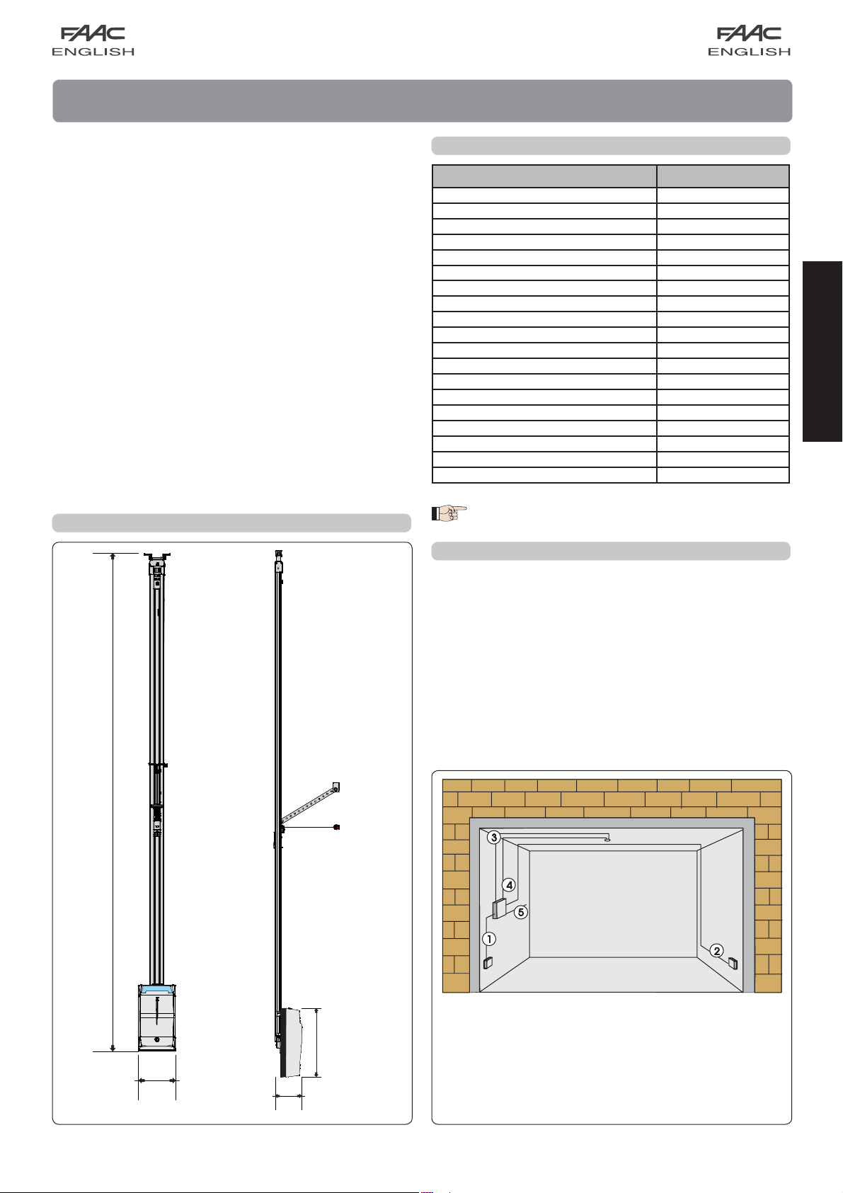
1. DIMENSIONS
Dimensions in mm.
2. TECHNICAL SPECIFICATIONS
Model D1000
Power supply (V ~ / 50 Hz.) 230
Electric motor (Vdc) 24
Maximum absorbed power (W) 350
Thrust force (N) 600/1000
Type of use continuous
Maximum dimensions from ceiling (mm) 35 (Fig. 4)
Courtesy light (V ~/W) 230 / 40 max.
Courtesy light timer (sec) 120
Standard speed with no-load carriage (m/min)
Slow speed with no-load carriage (m/min) 4,5
Carriage deceleration speed (m/min) 1,1
Noise at standard speed (dB(A)) 52
Travel length at deceleration
Intrinsic safety device Category 2
Maximum sectional door width (mm) 5000
Maximum sectional door height (mm) See useful travel
Sliding guide useful travel (mm) 2500 - 3100 - 3800
Protection class For indoor use only (IP20)
Operating ambient temperature (°C) -20 / +55
Varies according to set-up
8,9
The level of noise emission of operator D1000, referred
to the work station, is 52 dB(A).
3. ANCILLARY ELECTRICAL EQUIPMENT
Prepare the electric system in keeping with the instructions in
the chapter entitled “Warnings for the installer”.
When you have finished installing, check if any external pipes
or cables can come into contact with moving parts.
Install the fixed control points at a minimum height of 150 cm,
clear of the door movement area, but in a position enabling
visual control of that area.
ENGLISH
Fig. 1
2168 / 2768 / 3368
200
145
360
Cable 2 x 0.5 mm2 (TX photocell)
Cable 4 x 0.5 mm
2
(RX photocell)
Power pipe (230V)
Low voltage pipe
Cable 2 x 1.5 mm
4
2
(power)
Fig. 2
Page 5
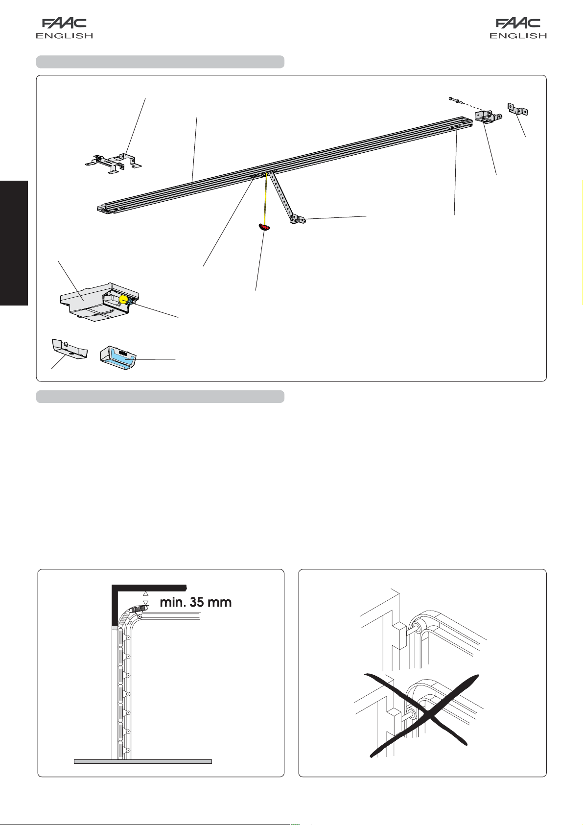
4. DESCRIPTION
ENGLISH
5. PRELIMINARY CHECKS
- The structure of the door must be suitable for fitting automation.
In particular, check that the door dimensions conform to
those indicated in the technical specifications, and that it is
sufficiently sturdy.
- Check if the door conforms to standards EN12604 and
EN12605.
- As it moves, the door must not encroach public areas
dedicated to pedestrian or vehicular transport.
- Check the efficiency of the door bearings and joints.
- Make sure that the door is friction-free. If necessary clean
and lubricate the guides with silicone based products, but do
not use grease, and, in any event, follow the manufacturer’s
instructions.
- Check correct balance and if the opening mechanical stops
Ceiling lamp
Rear door
Courtesy light
Plastic housing for D1000 operator
Rear fitting
Sliding guide
Drive carriage
Release knob
Door fitting bracket
Transmission unit
Front fitting and chain tensioner
Front fitting bracket
have been installed.
- Remove the door’s existing closing mechanism to ensure the
door is closed by the automated system.
- Make sure there is a clearance of at least 35 mm between the
ceiling and the highest sliding point of the door (Fig.4).
- Check if the upper guide roller of the sectional door is in the
horizontal part of the guide while the door is closed (fig. 5).
Fig. 3
Fig. 5Fig. 4
5
Page 6

6. ASSEMBLY
6.1. Sliding guide
If you use a sliding guide in two pieces, you must assemble it,
as explained below. If you have a pre-assembled guide, go
on to paragraph 6.2.
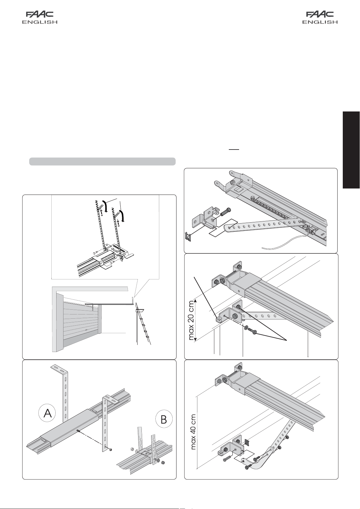
1) Assemble the two pieces of the sliding guide, fitting them
in the central joint (Fig. 6 ref. A) until they come to a stop
against the metal reference reliefs (Fig. 6 ref. B). To facilitate
engaging the sliding guide, we advise you to insert it in the
central joint, compressing it as shown in Fig. 6 ref. C. Do not
use tools which could deform the guide or joint.
2) Slide the transmission unit (Fig.7 ref. A) along the whole sliding
guide, until it is near the front terminal, the one opposite the
drive coupling.
3) Assemble the front fitting (Fig. 7 ref. B) to the transmission unit
(Fig. 7 ref. A).
4) Apply slight tension to the chain, tightening the nut (Fig. 7
ref. C.).
5) Place the sliding guide on the side (Fig. 8).
6) Push the carriage toward the drive clutch unit (Fig.8
ref. C).
7) Adjust the tensioner (fig. 8 ref. A) so that the central zone of
the loop, formed by the top branch of the chain, coincides
with about the mid-point of the sliding guide (Fig. 8 ref. B).
Attention: too much tension can cause damage to the
transmission and drive clutch units.
6.2. Rear fitting
Before securing the sliding guide to the ceiling, assemble the
rear fitting in the seat of the drive clutch unit and fasten the
screws as shown in Fig. 9 ref. .
ENGLISH
Fig. 6
Fig. 7 Fig. 9
Fig. 8
6
Page 7
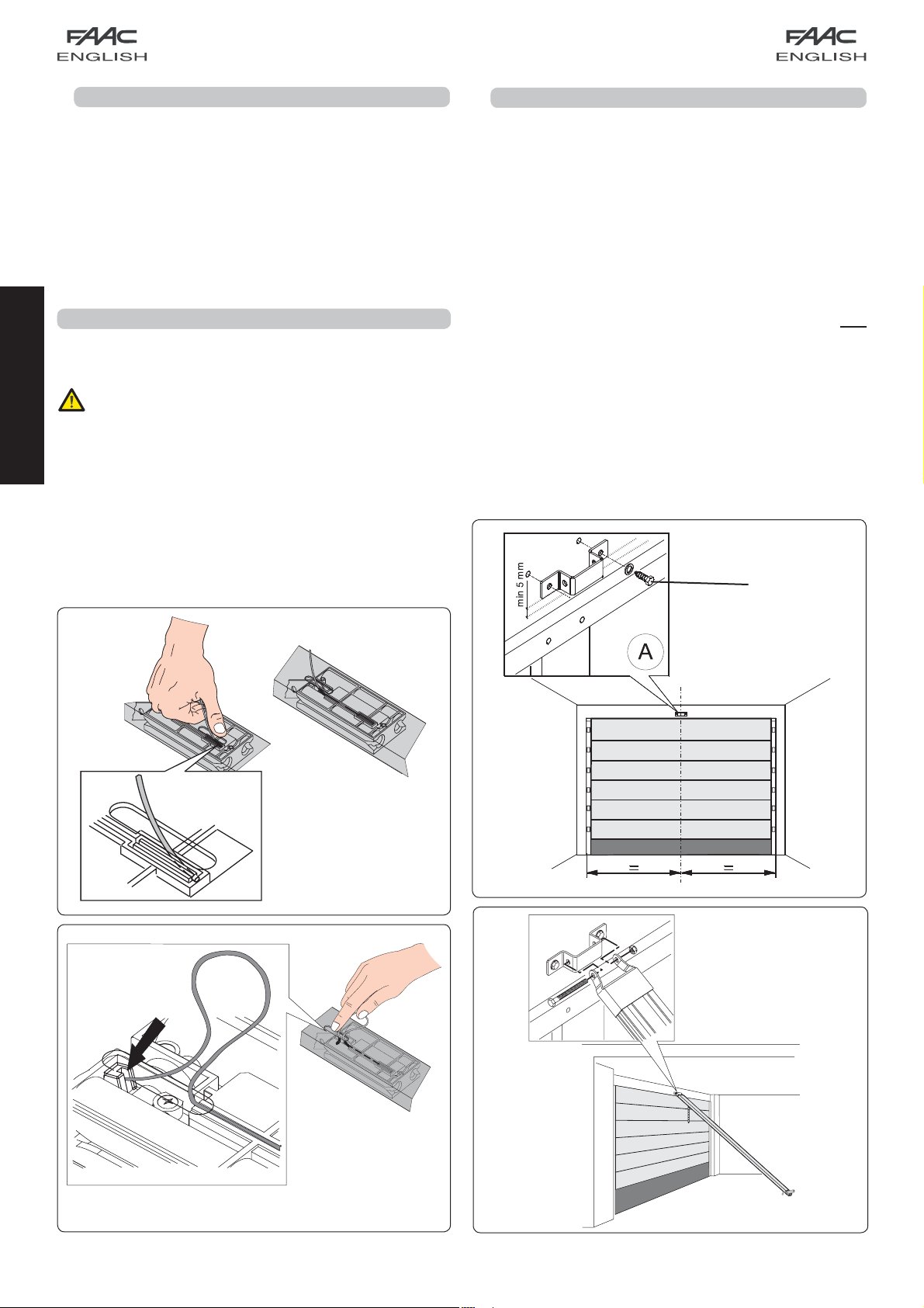
6.3. External release (optional)
If the external release system has to be installed, the cable
must be placed in its seat before beginning to install.
1) Release the carriage (see par. 7.4 point 3), and take it to
the slot on the top of the sliding guide.
2) Fit the cable terminal on the red seat (Fig. 10).
3) Take the carriage back toward the drive clutch unit until
the through-hole on the carriage coincides with the slot,
and fit the unsheathed cable (Fig. 11).
4) Fully withdraw the cable from the bottom of the
carriage.
5) Wind the cable around itself to prevent it getting in the way
while the sliding guide is being installed.
7. INSTALLATION
- To ensure you work in safe conditions, we advise you
to install the operator while keeping the door fully
closed.
- Use all the specified anchorage points.
- The fastening systems must be suitable for the type of
support and sufficiently tough.
ENGLISH
- Protect your hands and face adequately while drilling
the holes.
- Read this chapter to the full before you begin
installing.
7.1. Sliding guide
When you have finished the preliminary assembly operations,
you can begin installing the sliding guide, as follows:
1) On the architrave, mark a line corresponding to the vertical
mid-point of the door (Fig. 12).
2) On the architrave, mark a horizontal line corresponding to
the maximum height reached by the door during movement
(see Fig. 4).
3) Position the securing bracket of the front fitting, so that the
lower edge is at least 5 mm above the intersection point of
the lines and centred with respect to the vertical line (Fig.
12). Also refer to paragraph 7.2 for correct positioning of the
bracket with respect to the fitting point on the door.
4) Mark the two securing points.
5) Next, drill and install, using the screws (ref. Fig. 12) NOT
supplied.
6) Position the sliding guide on the floor, perpendicular with
respect to the door.
7) Lift guide off the front fitting and assemble the latter with
the securing bracket, using the through screw and nut (Fig.
13).
Fig. 10
Fig. 12
Fig. 11
Fig. 13
7
Page 8
8) Lift the sliding guide until the rear fitting is at the same level
as the front fitting, or until you reach the same inclination as
the door’s horizontal rail. If you are securing directly to the
ceiling, go to point 12.
9) Measure the distance between the ceiling and the
between-axis position of the nuts securing the rear fitting.
10) Bend the supplied brackets according to the measurement
you have taken (measure starting from the centre of the
bracket’s first slot).
11) Fit the brackets on the rear fitting and re-position the sliding
guide (Fig. 14).
12) Mark the on-ceiling securing points of the rear fitting and drill
(taking care to protect the sliding guide). Finish installing the
guide.
13) If using a two-piece guide with central joint (Fig. 15 ref. A) or
the central support for a single rail (Fig. 15 ref. B - optional),
secure to the ceiling, using the brackets and proceed
according to steps 9, 10 and 12 (Fig. 15).
7.2. On-door fitting
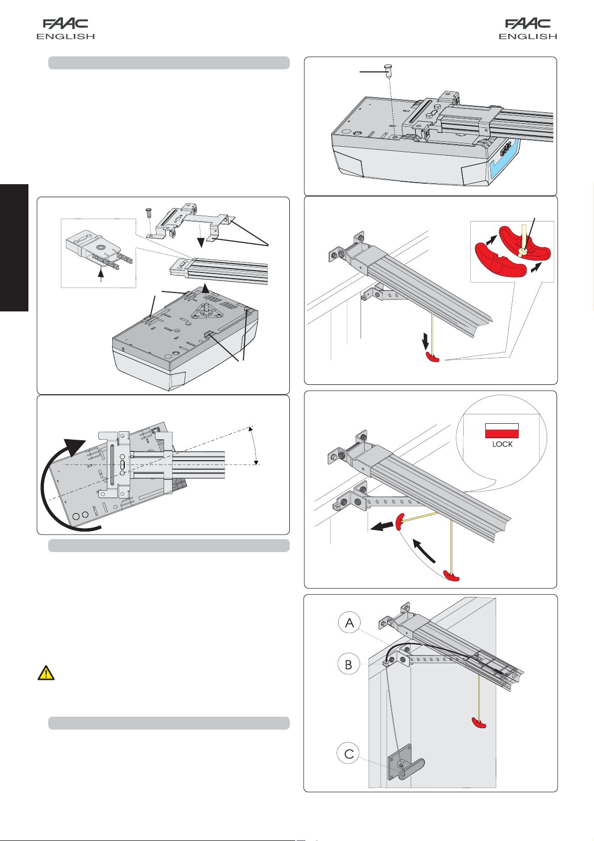
1) Assemble the fitting with the carriage rod (Fig. 16).
Position the fitting on the door so that the through-element
of the release cable is facing toward the left side of the door
(ref. Fig. 17).
2) Close the door and take the carriage near to it.
3) Position the fitting on the door, centred with respect to its
mid-point.
4) Make sure that the distance between the between-centres
of the securing holes of the front fitting and the on-door fitting
does not exceed 20 cm (Fig. 17). To ensure correct operation
of the automated system, we advise you to avoid arm
inclinations of over 30° compared to the sliding guide.
If using the curved arm for sectional doors (optional), carry
out the assembly with the straight arm of the carriage as
shown in Fig. 18. To improve efficiency of the anti-crushing
system, we advise you to secure the fitting on the sectional
door as low as possible, without, however, exceeding the
distance of 40 cm from the operator’s front fitting.
5) Mark, drill and secure the fitting to the door, using the screws
(ref. Fig. 17) NOT supplied.
Fig. 16
ENGLISH
Fig. 14
Fig. 17
Fig. 15 Fig. 18
8
Page 9
7.3. Operator
When you have assembled the rear fitting to the sliding guide
and finished installing the sliding guide, you can install the
operator:
1) While keeping the operator inclined at 15/20° (Fig. 20), insert
the gearmotor shaft in the coupling on the rear fitting of the
sliding guide and make the fins (Fig. 19 ref. ) near to the
seats at the bottom of the operator base (Fig. 19 ref. ).
2) Turn the operator in the direction of Fig. 20 until you reach
position of Fig. 21, and fit the pin in the hole of the rear fitting
(Fig.21 ref. ).
Fig. 21
ENGLISH
Fig. 19
15°/20°
Fig. 20
7.4. Releasing the automated system
1) Define the height of the release knob, taking into account
that it must not be over 180 cm off the ground, and cut off
the excess section of rope.
2) Make a knot at the end of the rope and assemble the release
handle (Fig. 22).
3) Pull the release handle down and check if the door can be
moved manually (Fig. 22).
4) Pull the release handle horizontally in the direction of the
door (Fig. 23). Check if, when the handle is released, the
LOCK window under the carriage is red. Move the door
manually until you find the carriage’s hook-on point.
Make sure that there are no persons, animals or objects in
the door movement area during the release manoeuvre.
Fig. 22
Fig. 23
7.5. External release
If the automated system has an external release, finish
installing (see par. 6.3):
1) Cut the cable sheath to size (Fig. 24 ref. A).
2) Fit the cable inside the sheath and route it through the eyelet
of the door fitting (Fig. 24 ref. B).
3) Cut the cable to size and assemble it together to the internal
lever of the release handle (Fig. 24 ref. C).
Fig. 24
9
Page 10

8. E1000 CONTROL BOARD
8.1. Technical specifications
Supply voltage (V ~ / Hz.)
Power supply to accessories (Vdc)
Accessories max. load (mA.)
Operating ambient temperature (°C)
Quick-fit connector
Operating logics
Terminal-board connections
Courtesy light timer (min.)
for receiver boards XF433 /
XF868 and battery module
Automatic / Semiautomatic
Open/Stop/Safety devices/Fail-
safe/Flashing lamp 24 Vdc
8.2. E1000 board components
J1 Low voltage inputs/accessories terminal board
Quick-fit connector for receivers XF433 or XF868
J2
J3 230V power supply input terminal board
J4 Connector for transformer primary winding
J5 Courtesy light terminal-board
J7 Connector for transformer secondary winding
J8 Motor output connector
J12 Battery module connector
OPEN A Radio signal programming push-button
OPEN B Radio signal programming push-button
OPEN OPEN push-button
SETUP SET-UP push-button
DS1 Programming dip-switch
LD1 Signalling LED: OPEN input
LD2 Signalling LED: STOP input
LD3 Signalling LED: FSW input
LD4 Signalling LED: SET UP cycle
LD5 LED signalling memory-storage: radio channel OPEN A
LD6 LED signalling memory-storage: radio channel OPEN B
TR1 Closing force adjustment
TR2 Opening force adjustment
230 / 50
24
200
-20 / +55
2
J1
LD3
LD1
LD2
SET UP
LD4
OPEN
J8
TR1
TR2
DS1
J2
LD5
J7
J12
OPEN BOPEN A
J5
LD6
J3
J4
Fig. 25
Fail Safe
If activated, it enables the photocell operating test before every
movement.
Operating logics
For doors with an irregular movement, it reduces the sensitivity of
the anti-crushing device to prevent unwanted action by it.
ENGLISH
8.3. Terminal-boards and connectors
Description Connected device
OPEN A
STOP
Command device with N.O. contact
(see chap. OPERATING LOGICS)
Device with N.C. contact which stops the
automated system
Negative for OPEN A and STOP devices
FSW
LAMP
-TX FSW
Closing safety device with N.C. contact (see
chap. OPERATING LOGICS)
OPEN COLLECTOR 24 Vdc 100 mA. output for
flashing lamp
Negative for powering safety accessories (FAIL
SAFE function)
Negative for powering accessories
+24 Vdc for powering accessories
8.4. DS1 Programming dip-switches
No. Function OFF ON
1 Fail Safe Enabled
Not enabled
2 Anti-crushing sensitivity Low High
3 Force adjustment Automatic Manual
4 Carriage speed High Low
Manual adjustment of force
If you wish to adjust force manually, before learning, turn ON
switch No. 3 of DS1, and manually adjust the thrust force with TR1
(closure) and TR2 (opening). Maximum available thrust is 1000N.
8.5. Operating logics
Logic A (automatic)
Status Open (pulse) Stop Fsw
CLOSED
OPENING No effect Locks (2) No effect (1)
OPEN IN
PAU S E
CLOSING Reverses motion Locks (2) Reverses motion
LOCKED Closes No effect (2) No effect (1)
Opens and closes
after pause time
Resumes counting of
pause time (1)
No effect (2) No effect
Locks (1)
Resumes counting of
pause time (1)
Logic E (semi-automatic)
Status Open (pulse) Stop Fsw
CLOSED Opens No effect (2) No effect
OPENING Locks Locks (2) No effect (1)
OPEN Closes No effect (2) No effect (1)
CLOSING Reverses motion Locks (2) Reverses motion
LOCKED Closes No effect (2) No effect (1)
10
Page 11
(1) Prevents closing if pulse is maintained.
(2) Prevents closing and/or opening if pulse is
maintained.
During the opening manoeuvre, the
anti-crushing device causes an immediate
stop. During the closing manoeuvre, it opens
the door.
If, during closure, an obstacle is detected more than
three consecutive times, the automated system
considers this distance as the new closing contact point
and goes into closed status. To restore the correct
positions, remove the obstacle and command a new
cycle: at the next closure, the automated system will
advance at low speed until it detects the contact point.
9. COURTESY LIGHT
- The courtesy light stays lighted for 2 minutes after the end of
the manoeuvre (cannot be modified).
ENGLISH
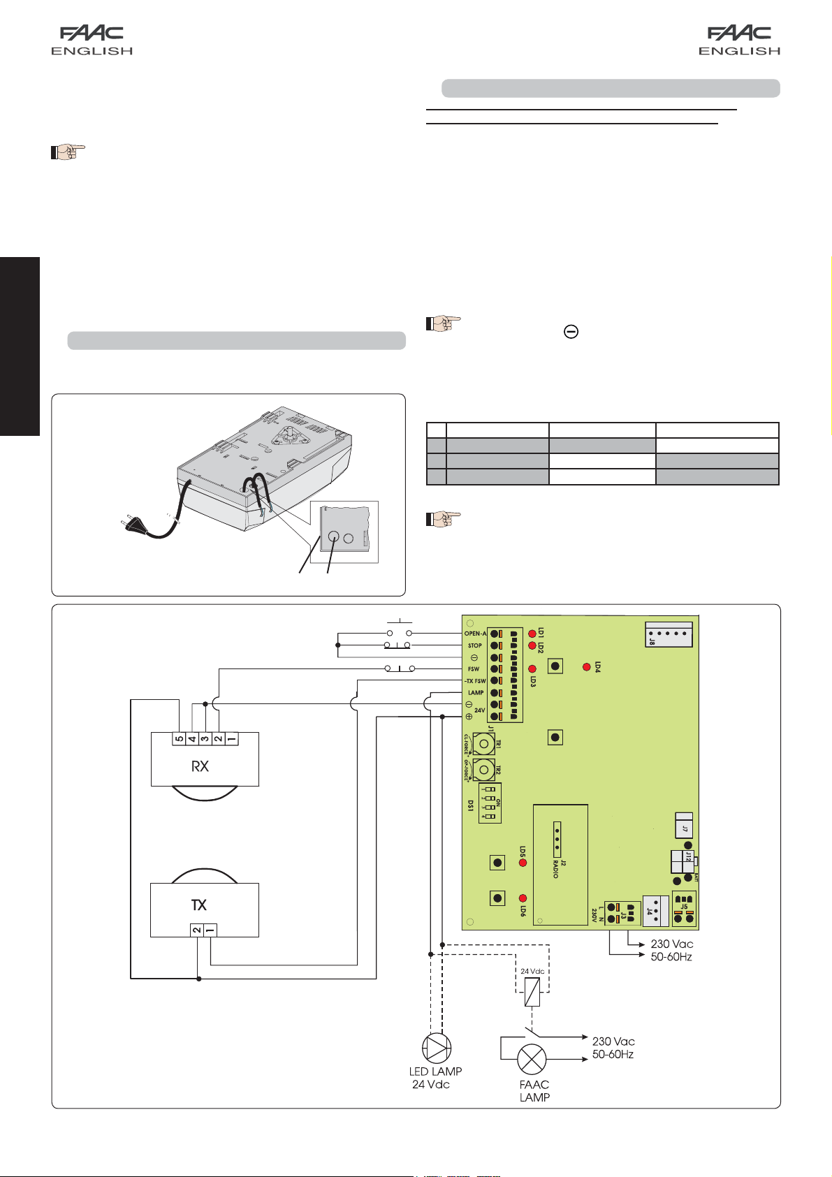
10. CONNECTIONS
IMPORTANT: Before attempting any work on the board
(connections, maintenance), always cut off power.
- To prevent any electric noise whatever, use separate sheaths
for powering the network, signals and accessories.
- The D1000 operator has a cable with a two-pole plug for 230
Vac power supply.
- To connect the external controls, safety devices and signals,
break open the pre-holed element (Fig. 26 ref. ).
- To connect the safety edge (see par. 18.3), break open the
pre-holed element (Fig. 26 ref. ).
- Make the electrical connections, referring to Fig. 27.
If the STOP input is not used, jumper connect the input
to the terminal
If the photocells are not used, connect the FSW
input to terminal -TX FSW.
Inputs status leds:
LD Meaning OFF ON
1 Input status OPEN Not enabled Enabled
2 Input status STOP Enabled Not Enabled
3 Input status FSW
.
Safety devices engaged Safety devices disengaged
Fig. 26
The automated system stopped and at rest is indicated
in bold for each input.
OPEN A
STOP
OTHER SAFETY DEVICES
11
Fig. 27
Page 12

11. PROGRAMMING
11.1. Setting the board
Set the appliance with Dip-Switch DS1 to obtain the operation
you require, referring to chapter 8.4.
If you wish to manually set the thrust force, turn ON
dip-switch 3 of DS1 and adjust potentiometers TR1
(CLOSURE) and TR2 (OPENING) BEFORE EFFECTING THE
LEARNING PROCEDURE. Turn clockwise to increase
thrust, and anti-clockwise to reduce it.
11.2. Learning (SET UP)
During the learning procedure, the obstacle detection device
does not operate. However, the STOP command and the
closing safety devices (FSW) are enabled; if they are triggered,
learning is interrupted and a fault is signalled.
The SETUP cycle is carried out with the plastic housing
installed. Just remove the rear door (Fig. 28).
Grip the rear door with both hands and pull gently
downward. When you have finished the procedure
described in this chapter, put the door back in place.
The learning cycle makes it possible to define the following:
Fig. 28
- the force required to move the door.
- the slow-down points.
- the opening and closing stop points.
- the pause time (in automatic logic).
For heavy doors or for movement problems, learning with a
1000N thrust instead of 600N (Default) is possible.
Learning must be started with the operator locked, irrespective
of the door’s position.
The procedure also determines the operating logic.
The logic tables indicate the behaviour of the automated
system in different conditions, and following commands or
action by the safety devices.
Learning can be automatic or manual. In the latter case, the
opening and closing deceleration points can be determined.
However, in automatic mode, the unit independently determines
the movement parameters.
If the procedure is not correctly concluded (e.g. due to excessive
friction during door movement), the unit signals a fault status
(the SET UP LED flashes slowly). In this case, the procedure must
be repeated after the cause is eliminated.
ENGLISH
AUTOMATIC LEARNING WITH LOGIC “E” (SEMI-AUTOMATIC)
Press the SET UP push-button for one second.
The SET UP LED starts to flash when you release the
push-button.
1) After 8 seconds the operator automatically closes the door
until the stop point is detected.
2) The operator begins the opening movement. Wait until the
stop point is reached, or give an OPEN command in the
position where you wish to stop motion.
3) The operator closes the door.
4) Wait for the door to reach the stop point and for the
operator to stop.
If the learning procedure terminated positively, the SET UP LED
stops flashing and stays lighted for 5 seconds.
RADIO SET UP
OPEN B
OPEN A
Radio signal programming push-button OPEN B.
RADIO SET UP LED signalling that the OPEN B radio signal is stored in the memory.
Radio signal programming push-button OPEN A.
RADIO SET UP LED signalling that the OPEN A radio signal is stored in the memory.
LED signalling the SET UP stage.
LED signalling photocells status.
LED signalling STOP.
LED signalling OPEN A.
OPEN push-button to totally open sectional door.
SET UP push-button for programming operating logics and learning work times.
FSW
SET UP
STOP
OPEN A
Fig. 29
12
Page 13

During these 5 seconds, in order to lighten the load on the
release system, you can send OPEN pulses within a time interval
of 2 seconds from each other, in order to reverse the carriage.
One pulse corresponds to a 5 millimetre travel.
N.B.: The carriage can be seen reversing only during normal
operation of the automated system.
The control unit establishes the deceleration points.
MANUAL LEARNING WITH LOGIC “E” (SEMI-AUTOMATIC)
Press the SET UP push-button for one second. The SET UP LED starts
to flash when you release the push-button. Start the following
procedure within 8 seconds (otherwise the operator will perform
automatic learning):
1) Give the 1st OPEN command: the operator performs a
slowed-down closing manoeuvre until it detects the stop
point and stops.
2) Give the 2nd OPEN command: the operator continues with
an opening movement.
3) Give the 3rd OPEN command in order to define the point
where you wish deceleration to begin.
ENGLISH
4) Give the 4th OPEN command to define the opening stop
point, or wait for the automated system to detect arrival at
the stop point and then stop.
5) Give the 5th OPEN command: the automated system begins
the closing movement.
6) Give the 6th OPEN command in order to define the point
where you wish deceleration to begin.
7) Wait for the door to reach the stop point and for the
operator to stop.
If the learning procedure terminated positively, the SET UP LED
stops flashing and stays lighted for 5 seconds.
During these 5 seconds, in order to lighten the load on the
release system, you can send OPEN pulses within a time interval
of 2 seconds from each other, in order to reverse the carriage.
One pulse corresponds to a 5 millimetre travel.
N.B.: The carriage can be seen reversing only during normal
operation of the automated system.
AUTOMATIC LEARNING WITH LOGIC “A” (AUTOMATIC)
Hold down the SET UP push-button until the SET UP LED goes
on (about 5 seconds). The SET UP LED starts to flash when you
release the push-button.
1) After 4 seconds the operator automatically closes the door
by deceleration until the stop point is detected.
2) The operator moves the door to open. Wait until the stop
point is reached, or give an OPEN command in the position
where you wish to stop motion.
3) The operator closes the door.
4) Wait for the door to reach the stop point and for the
operator to stop.
If the learning procedure terminated positively, the SET UP LED
stops flashing and stays lighted for 5 seconds.
During these 5 seconds, in order to lighten the load on the
release system, you can send OPEN pulses within a time interval
of 2 seconds from each other, in order to reverse the carriage.
One pulse corresponds to a 5 millimetre travel.
N.B.: The carriage can be seen reversing only during normal
operation of the automated system.
The control unit establishes the deceleration points.
Pause time is fixed at 3 minutes.
MANUAL LEARNING WITH LOGIC “A” (AUTOMATIC)
Hold down the SETUP push-button until the SET UP LED goes
on (about 5 seconds). The SET UP LED starts to flash when you
release the push-button. Start the following procedure within
4 seconds (otherwise the operator will perform automatic SET
UP).
1) Give the 1st OPEN command: the operator performs a
deceleration closing manoeuvre until it detects the stop
point.
2) Give the 2nd OPEN command: the operator continues with
an opening movement.
3) Give the 3rd OPEN command in order to define the point
where you wish deceleration to begin.
4) Give the 4th OPEN command to define the opening stop
point, or wait for the automated system to detect arrival at
the stop point. After the stop, the time when the automated
system is left open starts to be counted . This will be the pause
time which will be observed during manual operation (3
minutes maximum).
5) Give the 5th OPEN command: the pause time count is stopped
and the closing movement starts.
6) Give the 6th OPEN command in order to define the point
where you wish deceleration to begin.
7) Wait for the door to reach the stop point and for the
operator to stop.
If the learning procedure terminated positively, the SET UP LED
stops flashing and stays lighted for 5 seconds.
During these 5 seconds, in order to lighten the load on the
release system, you can send OPEN pulses within a time interval
of 2 seconds from each other, in order to reverse the carriage.
One pulse corresponds to a 5 millimetre travel.
N.B.: The carriage can be seen reversing only during normal
operation of the automated system.
LEARNING WITH THRUST FORCE OF 1000N
If learning is not performed correctly due to a heavy door or to
door movement problems, learning with a greater thrust force
(1000N instead of 600N) is possible.
How to start this type of learning:
1) Start the required learning cycle in the normal way.
2) While the automated system is performing the specified
movements, repeat the learning start procedure.
3) The automated system starts the learning cycle again, but
with a greater thrust.
ON GROUND MANUAL SETTING OF STOP CONTACT POINT (at the
learning stage)
During the learning stage, the operator searches for the
on-ground stop point, using the maximum force that can be
supplied (600/1000 N)). To prevent excessive stress, the stop point
can be determined also manually: when the automated system
performs the closing movements, give an OPEN command
when the stop point is reached. If the stop commands at first and
second closing were inconsistent, the automated system signals
the fault status and the learning cycle must be repeated.
During normal operation, the automated system in any case
searches for the stop contact point, but it exercises only the
force necessary to move the door.
The sensitivity of the anti-crushing device depends
on programming (anti-crushing sensitivity, manual
adjustment of force) and on the door’s mechanical
characteristics. When installation and programming
have been completed, always run the checks specified
in the regulations in chapter “WARNINGS FOR THE
INSTALLER” of these instructions.
When the learning cycle has finished, make the automated
system perform a complete cycle, in order to acquire
the correct closing stop point. If, after the end of this
cycle, the automated system opens the door again,
command closure.
13
Page 14

11.3 Pre-flashing
The pre-flashing function can be enabled and disabled
(following an OPEN command, the unit activates the flashing
lamp for 5 seconds before it starts the movement).
Procedure:
1) Press and hold down the SET UP push-button.
2) Press the OPEN push-button too after about 3 seconds. If the
SET UP LED goes ON, pre-flashing was activated, if instead,
it stays OFF, pre-flashing was disabled.
3) Release both push-buttons.12. MEMORY STORAGE OF RADIO
CONTROLS CODING
12. MEMORY STORAGE OF RADIO CONTROLS CODING
The control unit has an integrated 2-channel decoding system
(DS, SLH, LC) named OMNIDEC. This system makes it possible to
memory-store both total opening (OPEN A) and partial opening
(OPEN B) of the automated system - this is made possible by an
additional receiver module (Fig. 30 ref. ) and radio controls
on the same frequency.
RADIO SET UP
OPEN B OPEN A
Fig. 31
4) Within these 5 secs., press the appropriate push-button on
the radio control.
5) The relevant LED lights up on steady beam for 1 second and
then goes OFF, indicating that storage was executed.
6) To add other radio controls, set the same ON - OFF combination
used in point 1).
ENGLISH
Fig. 30
The 3 types of radio codes (DS, LSH, LC) cannot
coexist.
Only one radio code can be used at a time.
To change over from one code to another, you must
delete the existing one (see paragraph on deletion),
and repeat the memory-storage procedure.
12.1. Memory storage of radio controls DS
A maximum of two codes can be stored. One on the
OPEN A channel and one on the OPEN B channel
1) On the DS radio control, select the required ON-OFF combination
for the 12 dip-switches.
2) To respectively memory store total or partial opening, press
the OPEN A or OPEN B push-button for one second (Fig. 31
ref. )
3) The relevant LED (Fig. 31 ref ), begins to flash for 5 sec.
12.2. Memory storage of radio controls SLH
A Maximum of 250 codes can be memory stored, split
between OPEN A and OPEN B.
1) On the SLH radio control, simultaneously press and hold down
push-buttons P1 and P2.
2) The radio control LED begins to flash.
3) Release both push-buttons.
4) To respectively memory store total or partial opening, press
the OPEN A or OPEN B push-button for one second (Fig. 31
ref. ).
5) The relevant LED starts to flash slowly for 5 sec.
6) Within these 5 sec., while the radio control LED is still flashing,
press and hold down the required push-button on the radio
control (the radio control LED lights up on steady beam).
7) The LED on the board lights up on steady beam for 1 second
and then goes OFF, indicating that storage was executed.
8) Release the radio control push-button.
9) Quickly press twice in succession the memory stored radio
control push-button.
The automated system performs one opening operation.
Make sure that the automated system is free of any
obstacle created by persons or things.
10) To add other radio controls, transfer the code of the
memory-stored push-button of the radio control to the
relevant push-button of the radio controls to be added,
observing the following procedure:
- On the memory stored radio control, simultaneously press and
hold down push-buttons P1 and P2.
- The radio control LED begins to flash.
- Release both push-buttons.
- Press and hold down the memory-stored push-button (the radio
control LED lights up on steady beam).
- Approach the radio controls to each other and hold down the
push-button corresponding to the radio control to be added;
then release it after a double flash of the radio control LED
indicating that storage was executed.
14
Page 15

- Quickly press twice in succession the memory stored radio
control push-button.
The automated system performs one opening operation.
Make sure that the automated system is free of any
obstacle created by persons or things.
12.3 Memory storage of radio controls LC (for some markets
only)
A Maximum of 250 codes can be memory stored, split
between OPEN A and OPEN B.
1) Use LC remote controls only with receiver module at 433
MHz.
2) To respectively memory store total or partial opening, press
the OPEN A or OPEN B push-button for one second (Fig. 31
ref. ).
3) The relevant LED starts to flash slowly for 5 sec.
ENGLISH
4) Within these 5 secs., press the appropriate push-button on
the LC remote control.
5) The LED lights up on steady beam for 1 second, indicating
memory storage executed, and then resumes flashing for
another 5 sec., during which another radio control (point 4)
can be memory stored.
6) When the 5 secs. have elapsed, the LED goes OFF indicating
the end of the procedure.
7) To add other radio controls, repeat the operation from point
1).
All codes of radio controls stored as OPEN A and OPEN
B will be deleted.
13. START-UP
After installation, make sure that no part of the door
interferes with public spaces such as pavements and/or
roads.
Fig. 32
12.3.1 Remote memory storage of LC radio controls
Other radio controls can be remotely stored only with the LC
radio controls, i.e. without using the RADIO SETUP
push-buttons, but using a previously stored radio control.
1) Obtain a radio control already stored on one of the 2
channels (OPEN A or OPEN B).
2) Press and simultaneously hold down push-buttons P1 and P2
until the lights of both the LEDs on the board light up.
3) Both LEDs flash slowly for 5 sec.
4) Within 5 sec. press the push-button of the radio control that
had been memory stored to enable learning on the selected
channel (OPEN A or OPEN B).
5) The LED on the board relating to the channel being learned
flashes for 5 sec., within which time the code of another radio
control must be transmitted.
6) The LED lights up on steady beam for 2 seconds, indicating
memory storage executed, and then resumes flashing for 5
sec., during which other radio controls can be memory stored,
as in point 5, and then goes OFF.
12.4. Radio controls deletion procedure
1) To delete ALL the radio control codes, hold down push-button
OPEN A or OPEN B for 10 sec.
2) The LED relating to the pressed push-button flashes for the first
5 sec, and then flashes more quickly for the next 5 sec.
3) Both LEDs light up on steady beam for 2 sec and then go
OFF.
4) Release the pressed push-button when both LEDs light up on
a steady beam.
Fig. 33
Check the status of the unit’s inputs and make sure that all the
safety devices are correctly connected (the relevant LEDs must
be lighted).
Run a few complete cycles to check if the automated system
and the accessories connected to it are operating correctly,
addressing special care to the safety devices and the
anti-crushing device of the operator. Check if the automated
system is able to detect an obstacle with a height of 50mm laid
on the ground.
Apply the stickers indicating the release manoeuvre near the
automated system. Apply the danger signal sticker (Fig. 32), so
that it is clearly visible, near to the door or near to the control
device.
Hand the customer the page entitled “User’s guide”, and
describe how the system works, and the operator release and
locking operations indicated in the guide.
This operation is NOT reversible.
15
Page 16

14. PARACHUTE CABLES
Connect the parachute cables to the rear door and to the
ceiling lamp to prevent accidental falls (Fig. 33).
15. MAINTENANCE
Run a functional check of the system at least every 6 months,
with special attention to the efficiency of the safety and release
devices.
Once a month: check the efficiency of the anti-crushing device
and also check if it is able to detect a 50mm high obstacle laid
on the ground.
16. REPAIRS
For repairs, contact FAAC’s authorised Repair Centres.17.1.
Central support
The central support (Fig. 34) provides a central securing point
also for the single-piece sliding guide.
17. ACCESSORIES
17.1. Central support
The central support (Fig. 34) provides a central securing point
also for the single-piece sliding guide.
17.3. Safety edge CN60E
The use of the safety edge with conductive element, is
facilitated because the control unit (Fig. 36 ref ) can be
housed on board the operator.
Procedure:
- Grip the rear door with one hand.
- Pull gently, separating it from the plastic housing.
- Grip the ceiling light with one hand.
- Pull gently, separating it from the plastic housing.
- Unscrew the 4 screws in the 4 corners of the plastic housing.
- Separate it from the base.
- House the control unit as shown in Fig. 36.
- First hook on the two fastening clips on the coupling on the
base.
- Then press lightly until you can hear the hooking snap sound.
- For the connections, refer to the specific instructions for the
CN60E safety edge, and Fig. 27 of these instructions.
ENGLISH
Fig. 34
17.2. Key-operated release
The external release can be installed with the lever system
(Fig. 35 ref. A) or the key system (Fig. 35 ref. B). See instructions
in par. 6.3 and par. 7.5.
Fig. 36
17.4. Battery kit
The buffer battery kit will activate the automated system in
the event of a power cut. The batteries are housed inside the
operator (Fig. 37 ref. ) fastened by a supplied screw.
To install, consult the specific instructions.
The batteries come into operation when a power cut
occurs.
After installing the batteries, connect the male
connector to the J12 female connector on the E1000
control board.
Fig. 35
Fig. 37
16
Page 17

Trouble Possible causes Solution
When the learning procedure is started,
the SET UP LED flashes but the automated
system does not perform any
manoeuvre
The automated system does not
perform any movement
The automated system opens the door
but does not close it
Learning is not finished correctly and the
SET UP LED flashes to signal a fault
The automated system frequently
ENGLISH
reverses motion during the opening
and/or closing manoeuvre
It is difficult to release the automated
system while the door is closed
18. TROUBLESHOOTING
The STOP and FSW safety devices are
enabled also during the learning stage.
Non-connection or wrong connection
prevents the operator from working
STOP command enabled
The Fail-Safe function is enabled, but the
NC contact of the devices connected
to the FSW input does not open during
test by the unit before the manoeuvre
is started
FSW safety devices engaged
-The automated system detects that
the door movement is too difficult.
- If you are using manual adjustment of
force, the set thrust could be insufficient.
Too much mechanical load on the release
system with the door closed
Check the LEDs’ status following the
instructions of the “Inputs status LEDs”.
Check the connections shown in fig. 27
Check the balance of the door and
make sure that it moves without too much
friction. Move the door manually, using
the rod fitting on the door, and check
if the movement is smooth and does
not require too much traction or thrust.
Execute a new learning cycle. If necessary,
vary the thrust force (if using manual
adjustment) or start learning with a maximum thrust of 1000N.
Run a new learning cycle and,
when over, lighten the closing thrust,
commanding the carriage to withdraw
as described in paragraph 11.2.
The SET UP LED flashes to signal a fault
status
The learning cycle did not finish
positively.
DS1’s switch No. 3 (automatic/manual
adjustment of force) was shifted and a
new learning cycle was not executed.
Run a new learning cycle
17
Page 18

USER’s GUIDE D1000
Read the instructions carefully before using the product and store them for future use.
GENERAL SAFETY REGULATIONS
If correctly installed and used, the D1000 automated system will ensure a high degree of safety.
Some simple rules on behaviour can prevent accidental trouble:
- Do not, under any circumstances, stand under the door.
- Do not allow persons, animals or things to stay near the automated systems, especially while they are
operating.
- Transit must occur while the door is fully open and with the automated system stopped. Keep the door
under control during the entire movement and prevent other people accessing the area involved.
- Keep remote-controls, or other pulse generators that could open the door, well away from children.
- IMPORTANT! DANGER OF CRUSHING.
- Once a month: check if the anti-crushing system is able to detect the presence of a 50 mm high obstacle laid on the
ground.
- Do not allow children to play with the automated system.
- Do not willingly obstruct door movement.
- Prevent any branches or shrubs from interfering with door movement.
- Keep the indicator-lights efficient and easy to see.
- In the event of malfunctions, release the door to allow access and wait for qualified technical personnel to do the necessary
work.
- When you have set manual operation mode, cut power to the system before restoring normal operation.
- Do not in any way modify the components of the automated system.
- Do not attempt any kind of repair or direct action whatever and contact qualified FAAC personnel only.
- At least every six months: arrange a check by qualified personnel of the automated system and the safety devices.
DESCRIPTION
The D1000 automated system is ideal to automate balanced sectional doors of single garages for residential use.
The automated systems consist of an electro-mechanical operator, electronic control unit and courtesy light built into a single unit.
The system is non-reversing and, therefore, the door locks mechanically when the motor is not operating and, consequently, no lock is necessary;
a manual release makes it possible to move the door in case of a power cut or fault.
The automated system has an electronic obstacle detection system. If an obstacle is detected during the closing manoeuvre, the automated
system fully re-opens the door. If the automated system operates in automatic logic, the door re-closes
after the pause time, otherwise, a new pulse has to be given to command closure. If an obstacle is
detected during the opening manoeuvre, this will stop motion (e.g. thus preventing things and people
from being lifted). To restore normal operation, give a new opening pulse.
If, during closure, an obstacle is detected in the same position more than three consecutive times, the
automated system considers this distance as the new closing contact point and goes into closed status.
To restore the correct positions, remove the obstacle and command a new cycle: at the next closure,
the automated system will advance at low speed until it detects the closing contact point.
The door is normally closed; when the control unit receives an opening command by radio control,
or from another type of pulse generator (Fig. 1), it activates the electric motor which, by means of a
transmission chain or belt, pulls the door open to allow access.
- If the automatic mode was set, the door closes automatically after pause time has elapsed. An
opening pulse given during the opening stage has no effect.
- If the semi-automatic mode was set, a second pulse must be sent to close the leaf again.
- An opening pulse supplied during opening, stops movement. An opening pulse given during re-closing,
always causes movement to be reversed.
- A stop pulse (if specified) always stops movement.
For details of door activity during the different logics, consult the installation engineer.
Accessories (photocells) may be present in automated systems, that prevent the door from closing when
there is an obstacle in the area they control.
Emergency manual opening is possible by using the release system.
The indicator-light (if supplied) indicates the current door movement.
The courtesy light is activated when the motor starts and continues for about 2 minutes after it turns off.
If the courtesy light flashes, this means that automated system is in shut-down status due to a fault, and
qualified personnel must be called in to repair.
MANUAL OPERATION
The D1000 operator is equipped with an emergency release system activated from the inside – however,
a lock can be fitted on request, for activating the release from the outside too.
If the door has to be moved manually due to a power cut or fault of the automated system, use the
release device as follows:
- Turn off electric power to the system.
- Release the operator, by pulling the release handle downward (Fig. 2 ref. A).
Attention: make sure that there are no persons, animals or objects in the door movement area during
the release manoeuvre.
RESTORING AUTOMATIC OPERATION MODE
- Relock the automated system by pulling the handle horizontally (Fig. 2 ref. B) and make sure that, when
you release it, the “LOCK” window under the carriage is red, to confirm correct resetting.
- Move the door until you find the hook-on point.
- Power up the system.
MAINTENANCE
The D1000 automated system does not require any periodic replacement of parts.
COURTESY LIGHT REPLACEMENT
To replace the lamp, grip the ceiling light with one hand and pull downward, as shown in Fig. 3.
Unscrew the lamp (type E27 - 230 Vac - max 40 W) and re-position the ceiling light.
- Do not attempt to activate the door by hand unless you have released it.
RELEASE
RE-LOCK
Fig.1
Fig.2
Fig.3
Page 19

Technician
Customer 2Technician
Customer 3Technician
Customer 4Technician
Customer 5Technician
Customer 6Technician
Customer 7Technician
Customer 8Technician
Customer 9Technician
Customer 10Technician
Customer
Date Job description Signatures
No.
1
MAINTENANCE REGISTER
REGISTRO DI MANUTENZIONE
System data
System configuration
Installer
Customer
Start-up
Serial No.
Type of system
Installation date
PART MODEL SERIAL NUMBER
Operator
Safety device 1
Safety device 2
Control device 1
Pair of photocells 1
Control device 2
Pair of photocells 2
Radio control
Flashing lamp
Indication of residual risks and of foreseeable improper use
Page 20

D1000
D1000
Page 21

Page 22

GUIDA UTENTE D1000
Leggere attentamente le istruzioni prima di utilizzare il prodotto e conservarle per eventuali necessità
future.
NORME GENERALI DI SICUREZZA
L’automazione
curezza.
Alcune semplici norme di comportamento possono evitare inoltre inconvenienti accidentali:
- Non sostare assolutamente sotto alla porta.
- Non permettere a persone, animali o cose di sostare nelle vicinanze delle automazioni specialmente
durante il funzionamento.
- Il transito deve avvenire a porta totalmente aperta e con automazione ferma.Tenere sotto controllo la
porta per tutto il movimento ed impedire l’avvicinamento di altre persone all’area interessata.
- Tenere fuori dalla portata dei bambini radiocomandi o qualsiasi altro datore di impulso che possa
azionare la porta.
- In caso di malfunzionamenti, sbloccare la porta per consentire l’accesso ed attendere l’intervento tecnico di personale qualificato.
- Una volta predisposto il funzionamento manuale, prima di ripristinare il funzionamento normale, togliere alimentazione elettrica all’impianto.
- Non eseguire alcuna modifica sui componenti facenti parte il sistema di automazione.
- Astenersi da qualsiasi tentativo di riparazione o d’intervento diretto e rivolgersi solo a personale qualificato FAAC.
- Far verificare almeno semestralmente l’efficienza dell’automazione, dei dispositivi di sicurezza da personale qualificato.
DESCRIZIONE
L’ automazione
Le automazioni sono costituite da un operatore elettromeccanico, un‘apparecchiatura elettronica di controllo, una lampada di cortesia e un
carter di protezione integrati in un unico monoblocco.
Il sistema irreversibile garantisce il blocco meccanico della porta quando il motore non è in funzione e quindi non occorre installare alcuna serratura; uno sblocco manuale rende manovrabile la porta in caso di black-out o disservizio.
L’automazione è dotata di un sistema elettronico per il rilevamento di ostacolo. Se viene rilevato un ostacolo durante la manovra di chiusura, l’automazione riapre completamente la porta. Se l’automazione
funziona in logica automatica, la porta si richiuderà dopo il tempo di pausa, in caso contrario occorrerà
dare un nuovo impulso per comandare la chiusura. Durante la manovra di apertura, la rilevazione di
un ostacolo causa l’arresto del moto (ciò ad evitare sollevamento di cose o persone). Per ripristinare il
normale funzionamento occorre dare un nuovo impulso di apertura.
Se viene rilevato un ostacolo in chiusura nella stessa posizione per tre volte consecutive, l’automazione
assume tale quota come nuova battuta di chiusura e si pone in stato di chiuso. Per ripristinare le corrette
posizioni, rimuovere l’ostacolo e comandare un nuovo ciclo: alla successiva chiusura l’automazione
avanzerà a velocità rallentata fino ad individuare la battuta.
La porta normalmente si trova chiusa; quando la centralina elettronica riceve un comando di apertura
tramite il radiocomando, o qualsiasi altro datore di impulso (Fig. 1), aziona il motore elettrico che tramite
trasmissione a catena od a cinghia trascina il portone in posizione di apertura e consente l’accesso.
- Se è stato impostato il funzionamento automatico, la porta si richiude da sola dopo il tempo pausa.
Un impulso di apertura dato durante la fase di apertura non ha nessun effetto.
- Se è stato impostato il funzionamento semiautomatico, è necessario inviare un secondo impulso per
ottenere la richiusura.
- Un impulso di apertura dato durante la fase di apertura provoca l’ arresto del movimento. Un impulso
di apertura dato durante la fase di richiusura provoca sempre l’inversione del movimento.
- Un impulso di stop (se previsto) arresta sempre il movimento.
Per il dettagliato comportamento della porta nelle diverse logiche fare riferimento al Tecnico installatore.
Nelle automazioni possono essere presenti accessori (fotocellule) che impediscono la richiusura della
porta quando un ostacolo si trova nella zona da essi controllata.
L’apertura manuale d’emergenza è possibile intervenendo sull’apposito sistema di sblocco.
La segnalazione luminosa (se prevista) indica il movimento in atto della porta.
La luce di cortesia si attiva alla partenza del motore e permane per un tempo di circa 2 minuti dal suo
spegnimento. Se la lampada di cortesia lampeggia, l’automazione è in stato di blocco per anomalia
ed occorre richiedere l’intervento di personale qualificato per la riparazione.
FUNZIONAMENTO MANUALE
L’ operatore
a richiesta, applicare una serratura che permetta l’azionamento dello sblocco anche dall’esterno.
Nel caso sia necessario azionare la porta a causa di mancanza di alimentazione elettrica o disservizio
dell’automazione è necessario agire sul dispositivo di sblocco come segue:
- Togliere l’alimentazione elettrica all’impianto.
- Sbloccare l’operatore tirando verso il basso la maniglia di sblocco (Fig. 2 rif. A).
Attenzione: evitare che persone, animali od oggetti si trovino nella zona di movimento della porta durante la manovra di sblocco.
RIPRISTINO DEL FUNZIONAMENTO AUTOMATICO
- Ribloccare l’automazione tirando orizzontalmente la maniglia (Fig. 2 rif. B) ed accertarsi che, al rilascio,
la finestrella “LOCK” posta sotto al carrello sia di colore rosso, a conferma del corretto riarmo.
- Muovere la porta fino a ritrovare il punto di aggancio.
- Alimentare nuovamente l’impianto.
MANUTENZIONE
L’automazione
SOSTITUZIONE LAMPADA DI CORTESIA
Per la sostituzione della lampada, afferrare con una mano la plafoniera e tirare verso il basso, come
indicato in Fig. 3.
Svitare la lampada (tipo E27 - 230 Vac - max 40 W) e riposizionare la plafoniera.
D1000, se correttamente installata ed utilizzata, garantisce un elevato grado di si-
- ATTENZIONE! PERICOLO DI SCHIACCIAMENTO.
- Controllare mensilmente che il sistema antischiacciamento sia in grado di rilevare la presenza di un ostacolo alto
50 mm posto a terra.
- Non permettere a bambini di giocare con l’automazione.
- Non contrastare volontariamente il movimento della porta.
- Evitare che rami o arbusti possano interferire col movimento della porta.
- Mantenere efficienti e ben visibili i sistemi di segnalazione luminosa.
- Non tentare di azionare manualmente la porta se non dopo averla sbloccata.
D1000 è ideale per automatizzare porte sezionali bilanciate di garages singoli residenziali.
D1000 è dotato di un sistema di sblocco di emergenza azionabile dall’interno; è possibile,
D1000 non richiede alcuna sostituzione periodica di parti.
Fig.1
SBLOCCARE
RIBLOCCARE
Fig.2
Fig.3
Page 23

Tecnico
Cliente2Tecnico
Cliente3Tecnico
Cliente4Tecnico
Cliente5Tecnico
Cliente6Tecnico
Cliente7Tecnico
Cliente8Tecnico
Cliente9Tecnico
Cliente10Tecnico
Cliente
Nr Data Descrizione intervento Firme
1
REGISTRO DI MANUTENZIONE
Dati impianto
Configurazione impianto
Cliente
Installatore
Tipo impianto
Matricola
Attivazione
Data installazione
Operatore
COMPONENTE MODELLO MATRICOLA
Coppia fotocellule 1
Dispositivo di sicurezza 1
Dispositivo di sicurezza 2
Lampeggiante
Radiocomando
Coppia fotocellule 2
Dispositivo di comando 1
Dispositivo di comando 2
Indicazione dei rischi residui e dell’uso improprio prevedibile
Page 24

USER’s GUIDE D1000
Read the instructions carefully before using the product and store them for future use.
GENERAL SAFETY REGULATIONS
If correctly installed and used, the D1000 automated system will ensure a high degree of safety.
Some simple rules on behaviour can prevent accidental trouble:
- Do not, under any circumstances, stand under the door.
- Do not allow persons, animals or things to stay near the automated systems, especially while they are
operating.
- Transit must occur while the door is fully open and with the automated system stopped. Keep the door
under control during the entire movement and prevent other people accessing the area involved.
- Keep remote-controls, or other pulse generators that could open the door, well away from children.
- IMPORTANT! DANGER OF CRUSHING.
- Once a month: check if the anti-crushing system is able to detect the presence of a 50 mm high obstacle laid on the
ground.
- Do not allow children to play with the automated system.
- Do not willingly obstruct door movement.
- Prevent any branches or shrubs from interfering with door movement.
- Keep the indicator-lights efficient and easy to see.
- In the event of malfunctions, release the door to allow access and wait for qualified technical personnel to do the necessary
work.
- When you have set manual operation mode, cut power to the system before restoring normal operation.
- Do not in any way modify the components of the automated system.
- Do not attempt any kind of repair or direct action whatever and contact qualified FAAC personnel only.
- At least every six months: arrange a check by qualified personnel of the automated system and the safety devices.
DESCRIPTION
The D1000 automated system is ideal to automate balanced sectional doors of single garages for residential use.
The automated systems consist of an electro-mechanical operator, electronic control unit and courtesy light built into a single unit.
The system is non-reversing and, therefore, the door locks mechanically when the motor is not operating and, consequently, no lock is necessary;
a manual release makes it possible to move the door in case of a power cut or fault.
The automated system has an electronic obstacle detection system. If an obstacle is detected during the closing manoeuvre, the automated
system fully re-opens the door. If the automated system operates in automatic logic, the door re-closes
after the pause time, otherwise, a new pulse has to be given to command closure. If an obstacle is
detected during the opening manoeuvre, this will stop motion (e.g. thus preventing things and people
from being lifted). To restore normal operation, give a new opening pulse.
If, during closure, an obstacle is detected in the same position more than three consecutive times, the
automated system considers this distance as the new closing contact point and goes into closed status.
To restore the correct positions, remove the obstacle and command a new cycle: at the next closure,
the automated system will advance at low speed until it detects the closing contact point.
The door is normally closed; when the control unit receives an opening command by radio control,
or from another type of pulse generator (Fig. 1), it activates the electric motor which, by means of a
transmission chain or belt, pulls the door open to allow access.
- If the automatic mode was set, the door closes automatically after pause time has elapsed. An
opening pulse given during the opening stage has no effect.
- If the semi-automatic mode was set, a second pulse must be sent to close the leaf again.
- An opening pulse supplied during opening, stops movement. An opening pulse given during re-closing,
always causes movement to be reversed.
- A stop pulse (if specified) always stops movement.
For details of door activity during the different logics, consult the installation engineer.
Accessories (photocells) may be present in automated systems, that prevent the door from closing when
there is an obstacle in the area they control.
Emergency manual opening is possible by using the release system.
The indicator-light (if supplied) indicates the current door movement.
The courtesy light is activated when the motor starts and continues for about 2 minutes after it turns off.
If the courtesy light flashes, this means that automated system is in shut-down status due to a fault, and
qualified personnel must be called in to repair.
MANUAL OPERATION
The D1000 operator is equipped with an emergency release system activated from the inside – however,
a lock can be fitted on request, for activating the release from the outside too.
If the door has to be moved manually due to a power cut or fault of the automated system, use the
release device as follows:
- Turn off electric power to the system.
- Release the operator, by pulling the release handle downward (Fig. 2 ref. A).
Attention: make sure that there are no persons, animals or objects in the door movement area during
the release manoeuvre.
RESTORING AUTOMATIC OPERATION MODE
- Relock the automated system by pulling the handle horizontally (Fig. 2 ref. B) and make sure that, when
you release it, the “LOCK” window under the carriage is red, to confirm correct resetting.
- Move the door until you find the hook-on point.
- Power up the system.
MAINTENANCE
The D1000 automated system does not require any periodic replacement of parts.
COURTESY LIGHT REPLACEMENT
To replace the lamp, grip the ceiling light with one hand and pull downward, as shown in Fig. 3.
Unscrew the lamp (type E27 - 230 Vac - max 40 W) and re-position the ceiling light.
- Do not attempt to activate the door by hand unless you have released it.
RELEASE
RE-LOCK
Fig.1
Fig.2
Fig.3
Page 25

Technician
Customer 2Technician
Customer 3Technician
Customer 4Technician
Customer 5Technician
Customer 6Technician
Customer 7Technician
Customer 8Technician
Customer 9Technician
Customer 10Technician
Customer
Date Job description Signatures
No.
1
MAINTENANCE REGISTER
REGISTRO DI MANUTENZIONE
System data
System configuration
Installer
Customer
Start-up
Serial No.
Type of system
Installation date
PART MODEL SERIAL NUMBER
Operator
Safety device 1
Safety device 2
Control device 1
Pair of photocells 1
Control device 2
Pair of photocells 2
Radio control
Flashing lamp
Indication of residual risks and of foreseeable improper use
Page 26

INSTRUCTIONS POUR L’UTILISATEUR D1000
Instructions pour l’utilisateur
Lire attentivement les instructions avant d’utiliser le produit et les conserver pour toute nécessité future éventuelle.
RÈGLES GÉNÉRALES DE SÉCURITÉ
S’il est correctement installé et utilisé, l’automatisme D1000 garantit un haut niveau de sécurité.
Par ailleurs, quelques règles simples de comportement peuvent éviter bien des accidents:
- Ne jamais stationner sous la porte.
- Ne pas permettre aux personnes, aux animaux ou aux choses de stationner à proximité des automatismes
en particulier durant le fonctionnement.
- Ne transiter que lorsque la porte est totalement ouverte et que l’automatisme est arrêté. Contrôler la porte
durant tout le mouvement et empêcher d’autres personnes de s’approcher de la zone concernée.
- Éloigner de la portée des enfants: les radiocommandes ou tout autre dispositif générateur d’impulsion
en mesure d’actionner la porte.
- ATTENTION! DANGER D’ÉCRASEMENT.
- Contrôler tous les mois que le système anti-écrasement est en mesure de détecter la présence d’un obstacle d’une hauteur
de 50 mm placé au sol.
- Interdire aux enfants de jouer avec l’automatisme.
- Ne pas contraster volontairement le mouvement de la porte.
- Éviter que des branches ou des arbustes n’entravent le mouvement de la porte.
- Faire en sorte que les systèmes de signalisation lumineuse soient toujours efficients et bien visibles.
- N’actionner manuellement la porte qu’après l’avoir déverrouillée.
- En cas de dysfonctionnement, déverrouiller la porte pour permettre l’accès et attendre l’intervention technique du personnel qualifié.
- Lorsque le fonctionnement manuel a été disposé, couper le courant sur l’installation avant de rétablir le fonctionnement normal.
- N’effectuer aucune modification sur les composants qui font partie du système d’automation.
- Éviter toute tentative de réparation ou d’intervention directe et s’adresser uniquement à du personnel qualifié FAAC.
- Faire vérifier, au moins tous les six mois, l’efficience de l’automatisme, des dispositifs de sécurité par du personnel qualifié.
DESCRIPTION
L’ automatisme D1000 est l’idéal pour automatiser les portes sectionnales équilibrées de garages individuels domestiques.
Les automatismes sont constitués par un opérateur électromagnétique, une armoire électronique de contrôle, une lampe de courtoisie et un
carter de protection intégrés en un seul monobloc.
Le système irréversible garantit le blocage mécanique de la porte quand le moteur n’est pas en fonction; il n’et donc pas nécessaire d’installer
de serrure; un déverrouillage manuel permet de manœuvrer la porte en cas de coupure de courant ou de dysfonctionnement.
L’automatisme est équipé d’un système électronique de détection d’obstacles. Si un obstacle est détecté
durant la manœuvre de fermeture, l’automatisme rouvre complètement la porte. Si l’automatisme
fonctionne en logique automatique, la porte se referme à la fin du temps de pause; dans le cas contraire,
donner une nouvelle impulsion pour commander la fermeture. Durant la manœuvre d’ouverture, la
détection d’un obstacle provoque l’arrêt du mouvement (pour éviter le soulèvement de choses ou de
personnes). Pour rétablir le fonctionnement normal, donner une nouvelle impulsion d’ouverture.
Si un obstacle est détecté en fermeture dans la même position trois fois de suite, l’automatisme
considère cette cote comme une nouvelle butée de fermeture et se met en état de fermé. Pour rétablir
les positions correctes, enlever l’obstacle et commander un nouveau cycle: à la fermeture successive,
l’automatisme avancera à une vitesse ralentie jusqu’à l’identification de la butée.
La porte est normalement fermée; quand la centrale électronique reçoit une commande d’ouverture
par l’intermédiaire de la radiocommande ou de tout autre générateur d’impulsions (Fig. 1), elle actionne
le moteur électrique qui, par l’intermédiaire de la transmission à chaîne ou à courroie entraîne la porte
en position d’ouverture et permet l’accès.
- Si l’on a sélectionné le fonctionnement automatique, la porte se referme d’elle-même après le temps
de pause. Une impulsion d’ouverture donnée durant la phase d’ouverture n’a aucun effet.
- Si l’on a sélectionné le fonctionnement semi-automatique, envoyer une deuxième impulsion pour
obtenir la refermeture.
- Une impulsion d’ouverture donnée durant la phase d’ouverture provoque l’ arrêt du mouvement. Une
impulsion d’ouverture donnée durant la phase de refermeture provoque l’inversion du mouvement.
- Une impulsion de stop (si elle est prévue) arrête toujours le mouvement.
Pour le comportement détaillé de la porte dans les différentes logiques, s’adresser au Technicien installateur.
Les automatismes peuvent présenter des accessoires (photocellules) empêchant la refermeture de la
porte en présence d’un obstacle dans la zone qu’ils contrôlent.
L’ouverture manuelle d’urgence est possible en intervenant sur le système de déverrouillage spécifique.
La signalisation lumineuse (si elle est prévue) indique que la porte est en mouvement.
La lampe de courtoisie s’allume au démarrage du moteur et reste allumée pendant une durée d’environ
2 minutes après son extinction. Si la lampe de courtoisie clignote, l’automatisme est en état de blocage
dû à une anomalie; il faut donc demander l’intervention du personnel qualifié pour la réparation.
FONCTIONNEMENT MANUEL
L’ opérateur D1000 est équipé d’un système de déverrouillage d’urgence à actionner de l’intérieur; sur
demande, on peut appliquer une serrure permettant également l’actionnement du déverrouillage de
l’extérieur.
S’il est nécessaire d’actionner la porte en raison d’une coupure de courant ou d’un dysfonctionnement
de l’automatisme, agir sur le dispositif de déverrouillage comme suit:
- Couper le courant électrique sur l’installation.
- Déverrouiller l’opérateur en tirant la poignée de déverrouillage vers le bas (Fig. 2 réf. A).
Attention: éviter que des personnes, des animaux ou des objets ne se trouvent dans la zone de
mouvement de la porte durant la manœuvre de déverrouillage.
RÉTABLISSEMENT DU FONCTIONNEMENT AUTOMATIQUE
- Bloquer de nouveau l’automatisme en tirant la poignée horizontalement (Fig. 2 réf. B) et s’assurer qu’ au relâchement,
la fenêtre “LOCK” sous le chariot est de couleur rouge, confirmant le réarmement correct.
- Actionner la porte pour retrouver le point d’accrochage.
- Remettre l’installation sous tension.
ENTRETIEN
L’automatisme D1000 n’exige pas le remplacement périodique de pièces.
REMPLACEMENT DE LA LAMPE DE COURTOISIE
Pour le remplacement de l’ampoule, saisir le plafonnier d’une main et tirer vers le bas, d’après la Fig.3.
Dévisser l’ampoule (type E27 – 230 Vca – 40 W maxi) et remettre le plafonnier en place.
DÉVERROUILLER
BLOQUER DE NOUVEAU
Fig.1
Fig.2
Fig.3
Page 27

Technicien
Client 2Technicien
Client 3Technicien
Client 4Technicien
Client 5Technicien
Client 6Technicien
Client 7Technicien
Client 8Technicien
Client 9Technicien
Client 10Technicien
Client
Date Description de l’intervention Signatures
N°
1
REGISTRE D’ENTRETIEN
REGISTRO DI MANUTENZIONE
Données de l’installation
Configuration de l’installation
Client
Installateur
Type d’installation
Activation
N° de série
Date d’installation
Opérateur
COMPOSANT MODÈLE N° DE SERIE
Dispositif de sécurité 1
Dispositif de sécurité 2
Radiocommande
Paire de photocellules 1
Paire de photocellules 2
Dispositif de commande 1
Lampe clignotante
Dispositif de commande 2
Indication des risques résiduels et de l’usage impropre prévisible
Page 28

ANLEITUNGEN FÜR DEN BENUTZER D1000
Anleitungen für den Benutzer
Vor der Verwendung des Produkts sind die Anweisungen aufmerksam zu lesen und dann für den
eventuellen zukünftigen Bedarf aufzubewahren.
ALLGEMEINE SICHERHEITSVORSCHRIFTEN
Bei korrekter Installation und sachgemäßer Anwendung gewährleistet die Automation D1000 ein hohes
Sicherheitsniveau.
Einige einfache Verhaltensregeln können außerdem ungewollte Störungen vermeiden:
- Auf keinen Fall unter dem Tor aufhalten.
- Personen, Tiere oder Dinge dürfen sich nicht in der Nähe der Automationen, insbesondere während des
Betriebs, befinden.
- Der Durchgang bzw. die Durchfahrt muss bei vollständig geöffnetem Tor und still stehender Automation erfolgen. Das Tor während der gesamten
Bewegung kontrollieren und verhindern, dass andere Personen sich dem betreffenden Bereich nähern.
- Funksteuerungen oder andere Impulsgeber, die das Tor betätigen können, sind außerhalb der Reichweite von Kindern
aufzubewahren.
- ACHTUNG! QUETSCHGEFAHR.
- Monatlich überprüfen, ob das Quetschschutzsystem in der Lage ist, ein 50 mm hohes, auf dem Boden liegendes Hindernis
zu erfassen.
- Kinder dürfen nicht mit der Automation spielen.
- Die Bewegung des Tors darf nicht absichtlich behindert werden.
- Vermeiden, dass Zweige oder Büsche die Bewegung des Tors beeinträchtigen.
- Darauf achten, dass die Leuchtsignalsysteme stets funktionstüchtig und gut sichtbar sind.
- Das Tor darf nur dann mit der Hand betätigt werden, wenn es entriegelt wurde.
- Bei Betriebsstörungen das Tor mit der Hand entriegeln, um den Zutritt/die Zufahrt zu ermöglichen und technische Fachkräfte benachrichtigen.
- Wenn der Handbetrieb eingestellt ist, muss vor der Wiederherstellung des Normalbetriebs die Stromzufuhr zur Anlage unterbrochen werden.
- Keine Änderungen an den Bauteilen des Automationssystems vornehmen.
- Keine Reparaturen oder direkten Arbeiten selbst ausführen und sich nur an Fachtechniker der Firma FAAC wenden.
- Im Abstand von mindestens 6 Monaten die Funktionstüchtigkeit der Automation, der Sicherheitsvorrichtungen von Fachkräften prüfen lassen.
BESCHREIBUNG
Die Automation D1000 ist ideal für die Automatisierung von ausgeglichenen Sektionaltoren von Einzelgaragen in Wohngebäuden.
Die Automationen bestehen aus einem elektromechanischen Antrieb, einem elektronischen Steuergerät, einer Servicelampe und einem Schutzgehäuse,
die in ein einziges Kompaktteil integriert sind.
Das irreversible System gewährleistet die mechanische Verriegelung des Tors, wenn der Motor nicht läuft,
daher muss kein Schloss eingebaut werden. Durch eine manuelle Entriegelung kann das Tor bei Stromausfall
oder Betriebsstörungen bewegt werden.
Die Automation ist mit einem elektronischen System für die Hinderniserfassung ausgerüstet. Wenn ein
Hindernis während des Schließens erfasst wird, öffnet die Automation erneut vollständig das Tor. Wenn der
Automatikbetrieb eingestellt wurde, schließt sich das Tor nach einer Pausenzeit, anderenfalls ist ein neuer
Impuls für die Steuerung des Schließvorgangs erforderlich. Während des Öffnens verursacht die Erfassung eines
Hindernisses den Stillstand der Bewegung (dies geschieht um zu vermeiden, dass Gegenstände oder Personen
angehoben werden). Zur Wiederherstellung des Normalbetriebs ist ein neuer Öffnungsimpuls erforderlich.
Wenn ein Hindernis drei Mal hintereinander beim Schließen an derselben Stelle erfasst wird, erkennt die
Automation diese Position als neuen Schließanschlag und setzt sich in den Zustand „geschlossen“. Für die
Wiederherstellung der korrekten Positionen das Hindernis entfernen und einen neuen Zyklus fahren: Beim
nächsten Schließen fährt die Automation bei verlangsamter Geschwindigkeit bis sie den Anschlag
ermittelt.
In der Regel ist das Tor geschlossen. Wenn die elektronische Steuerung einen Öffnungsimpuls über die
Funksteuerung oder einen beliebigen anderen Impulsgeber empfängt (Abb. 1), wird der Elektromotor in
Betrieb gesetzt, der das Tor über einen Ketten- oder Riemenantrieb öffnet und Zugang/Zufahrt ermöglicht.
- Wenn der Automatikbetrieb eingestellt wurde, schließt sich das Tor selbsttätig nach der Pausenzeit. Ein
während der Öffnung gesendeter Öffnungsimpuls hat keinerlei Wirkung.
- Wenn der halbautomatische Betrieb eingestellt wurde, muss ein zweiter Impuls gesendet werden, damit
sich das Tor wieder schließt.
- Wenn beim Öffnen ein Impuls für die Öffnung gesendet wird, wird die Bewegung angehalten. Wenn beim
Schließen ein Impuls für die Öffnung gesendet wird, erfolgt stets die Umkehrung der Bewegung.
- Ein Halteimpuls (wenn vorgesehen) stoppt stets die Bewegung.
Für die detaillierte Beschreibung des Verhaltens des Tors mit den verschiedenen Steuerungslogiken wenden
Sie sich bitte an den mit der Installation beauftragten Techniker.
Die Automationen können Zubehörteile (Fotozellen) enthalten, die das erneute Schließen des Tors verhindern,
wenn sich ein Hindernis in dem jeweiligen abgesicherten Bereich befindet.
Die Notöffnung per Hand kann mit Hilfe des entsprechenden Entriegelungssystems ermöglicht werden.
Das Leuchtsignal (wenn vorgesehen) signalisiert die laufende Torbewegung.
Die Servicelampe geht beim Anlaufen des Motors an und geht etwa 2 Minuten nach dem Stillstand des
Motors aus. Wenn die Servicelampe blinkt, ist die Automation aufgrund einer Störung blockiert. Qualifizierte
Fachkräfte für die Reparatur benachrichtigen.
HANDBETRIEB
Der Antrieb D1000 ist mit einem System für die Notentrieglung von innen ausgerüstet. Auf Anfrage kann ein
Schloss angebracht werden, durch das die Betätigung der Entriegelung auch von außen möglich ist.
Sollte es aufgrund von Stromausfall oder Betriebsstörungen der Automation erforderlich sein, das Tor mit der
Hand zu betätigen, sind folgende Maßnahmen an der Entriegelungsvorrichtung vorzunehmen:
- Die Stromzufuhr zur Anlage unterbrechen.
- Den Antrieb entriegeln und hierzu den Freigabeknauf nach unten ziehen (Abb. 2 Bez. A).
Achtung: Vermeiden, dass sich Personen, Tiere oder Gegenstände während der Entriegelung im
Bewegungsbereich des Tors aufhalten bzw. befinden.
WIEDERHERSTELLUNG DES AUTOMATIKBETRIEBS
- Die Automation erneut verriegeln und hierzu den Griff waagrecht ziehen (Abb. 2 Bez. B) und sicherstellen,
dass das Fenster „LOCK“ unterhalb des Schlittens beim Loslassen rot ist. Dies bedeutet, dass der Betrieb
ordnungsgemäß wiederhergestellt wurde.
- Das Tor bis zur Kupplungsstelle bewegen.
- Die Anlage wieder mit Strom versorgen.
WARTUNG
Bei der Automation D1000 müssen keine Teile regelmäßig ausgewechselt werden.
AUSWECHSELN DER SERVICELAMPE
Zum Auswechseln der Servicelampe ist die Deckenbefestigung mit einem Hand zu greifen und nach unten
zu ziehen, wie in der Abb. 3 angegeben.
Die Birne herausschrauben (Typ E27 - 230 Vac - max 40 W) und die Deckenbefestigung wieder montieren.
ENTRIEGELN
VERRIEGELN
Fig.1
Abb.2
Abb.3
Page 29

Techniker
Kunde 2Techniker
Kunde 3Techniker
Kunde 4Techniker
Kunde 5Techniker
Kunde 6Techniker
Kunde7Techniker
Kunde 8Techniker
Kunde 9Techniker
Kunde 10Techniker
Kunde
Datum Beschreibung der Arbeiten Unterschrift
Nr.
1
WARTUNGSPROGRAMM
REGISTRO DI MANUTENZIONE
Daten der Anlage
Konfiguration der Anlage
Kunde
Monteur
Art der Anlage
Seriennummer
Inbetriebnahme
Installationsdatum
Antrieb
BAUTEIL MODELL SERIENNUMMER
Sicherheitsvorrichtung 1
Sicherheitsvorrichtung 2
Fotozellenpaar 1
Fotozellenpaar 2
Schaltvorrichtung 1
Schaltvorrichtung 2
Blinkleuchte
Funksteuerung
Angabe der Restrisiken und der voraussehbaren unsachgemäßen Anwendung
Page 30

GUÍA PARA EL USUARIO D1000
Guía para el usuario
Lea detenidamente las instrucciones antes de utilizar el producto y consérvelas para posibles usos
futuros.
NORMAS GENERALES DE SEGURIDAD
La automación D1000, si se instala y utiliza correctamente, garantiza un elevado grado de seguridad.
Algunas simples normas de comportamiento pueden evitar inconvenientes o accidentes:
- No se detenga absolutamente debajo de la puerta.
- No permita que personas, animales u objetos estén detenidos cerca de la automación, especialmente
durante el funcionamiento.
- Sólo puede transitarse con la puerta completamente abierta y con la automación parada. Mantenga
bajo control la puerta durante todo el movimiento e impida que otras personas se acerquen al área
interesada.
- Mantenga fuera del alcance de los niños los radiomandos o cualquier otro generador de impulsos para evitar que la
automación pueda accionarse involuntariamente.
- ¡ATENCIÓN! PELIGRO DE APLASTAMIENTO.
- Compruebe mensualmente que el sistema antiaplastamiento pueda detectar la presencia de un obstáculo
de 50 mm de altura situado en el suelo.
- No permita que los niños jueguen con la automación.
- No obstaculice voluntariamente el movimiento de la puerta.
- Evite que ramas o arbustos interfieran con el movimiento de la puerta.
- Mantenga en buen estado y bien visibles los sistemas de señalización luminosa.
- No intente accionar manualmente la puerta si no está desbloqueada.
- En caso de mal funcionamiento, desbloquee la puerta para permitir el acceso y espere a que personal técnico cualificado intervenga para
solucionar el problema.
- Una vez preparado el funcionamiento manual, quite la alimentación eléctrica al equipo antes de reanudar el funcionamiento normal.
- No efectúe ninguna modificación en los componentes que formen parte del sistema de automación.
- Absténgase de intentar reparar o de intervenir directamente, diríjase exclusivamente a personal cualificado FAAC.
- Haga verificar por lo menos semestralmente el funcionamiento de la automación y de los dispositivos de seguridad por personal cualificado.
DESCRIPCIÓN
La automación D1000 es ideal para automatizar puertas seccionales equilibradas de garajes individuales residenciales.
Las automaciones están formadas por un operador electromecánico, un equipo electrónico de control, una luz de cortesía y un cárter de protección
integrados en un único monobloque.
El sistema irreversible garantiza el bloqueo mecánico de la puerta cuando el motor no está en funcionamiento, por lo que no es necesario instalar
cerradura alguna; un desbloqueo manual permite maniobrar la puerta en caso de falta de alimentación eléctrica o de avería.
La automación está provista de un sistema electrónico para la detección de obstáculos. Si se detecta un obstáculo durante la maniobra de cierre, la
automación abre de nuevo completamente la puerta. Si la automación funciona en lógica automática,
la puerta se volverá a cerrar después del tiempo de pausa, en caso contrario será necesario dar un nuevo
impulso para mandar el cierre. Durante la maniobra de apertura, si se detecta un obstáculo, se detiene el
movimiento (esto para evitar la elevación de personas o cosas). Para restablecer el normal funcionamiento
hay que dar un nuevo impulso de apertura.
Si durante el cierre se detecta un obstáculo en la misma posición durante tres veces consecutivas, la
automación toma dicha cota como nuevo tope de cierre y se pone en estado de cerrado. Para restablecer
las correctas posiciones, elimine el obstáculo y mande un nuevo ciclo: al siguiente cierre la automación
avanzará a velocidad reducida hasta localizar el tope.
La puerta normalmente está cerrada; cuando la centralita electrónica recibe un mando de apertura
mediante un radiomando, o cualquier otro generador de impulsos (Fig. 1), acciona el motor eléctrico
el cual, mediante transmisión de cadena o de correa, arrastra el portón hasta la posición de apertura y
permite el acceso.
- Si se ha programado el funcionamiento automático, la puerta se cierra sola transcurrido el tiempo de
pausa. Un impulso de apertura durante la fase de apertura no tiene ningún efecto.
- Si se ha programado el funcionamiento semiautomático, es necesario enviar un segundo impulso
para obtener el cierre.
- Un impulso de apertura durante la fase de apertura detiene el movimiento. Un impulso de apertura
durante la fase de cierre causa siempre la inversión del movimiento.
- Un impulso de stop (si estuviera previsto) detiene siempre el movimiento.
Para conocer en detalle el comportamiento de la puerta en las diferentes lógicas de funcionamiento,
consulte al Técnico instalador.
En las automaciones pueden estar presentes accesorios (fotocélulas) que impiden que la puerta se cierre
cuando hay un obstáculo en la zona por las mismas controladas.
La apertura manual de emergencia sólo es posible si se interviene en el correspondiente sistema de
desbloqueo.
La señalización luminosa (si estuviera prevista) indica el movimiento en acto de la puerta.
La luz de cortesía se activa cuando arranca el motor y permanece encendida durante unos 2 minutos
después de que se apaga el motor. Si la luz de cortesía destella significa que la automación está
bloqueada debido a una anomalía, por lo que hay que solicitar la intervención de personal cualificado
para la reparación.
FUNCIONAMIENTO MANUAL
El operador D1000 está dotado de un sistema de desbloqueo de emergencia que puede accionarse desde
el interior; bajo pedido se puede aplicar una cerradura que permita el accionamiento del desbloqueo
también desde el exterior.
Si fuera necesario mover la puerta, por ejemplo por un corte de corriente o un fallo de la automación, es
necesario manipular el dispositivo de desbloqueo del siguiente modo:
- Quite la alimentación eléctrica del equipo.
- Desbloquee el operador tirando hacia abajo la manilla de desbloqueo (Fig. 2 ref. A).
Atención: evite que personas, animales u objetos estén en la zona de movimiento de la puerta durante
la maniobra de desbloqueo.
RESTABLECIMIENTO DEL FUNCIONAMIENTO AUTOMÁTICO
- Bloquee de nuevo la automación tirando horizontalmente de la manilla (Fig. 2 ref. B) y asegúrese de
que, al soltarla, la ventanilla “LOCK” situada debajo del carro sea de color rojo, para confirmar que
se ha rearmado correctamente.
- Mueva la puerta hasta encontrar el punto de enganche.
- Alimente de nuevo el equipo.
MANTENIMIENTO
La automación D1000 no requiere la sustitución periódica de piezas.
SUSTITUCIÓN DE LA LUZ DE CORTESÍA
Para sustituir la luz aferre con una mano el plafón y tire del mismo hacia abajo, como se indica en la Fig. 3.
Desenrosque la bombilla (tipo E27 - 230 Vac - máx. 40 W) y coloque de nuevo el plafón.
DESBLOQUEAR
BLOQUEAR
Fig.1
Fig.2
Fig.3
Page 31

Técnico
Cliente 2Técnico
Cliente3Técnico
Cliente4Técnico
Cliente5Técnico
Cliente6Técnico
Cliente 7Técnico
Cliente8Técnico
Cliente9Técnico
Cliente 10Técnico
Cliente
Fecha Descripción de la intervención Firma
N°
REGISTRO DI MANUTENZIONE
REGISTRO DE MANTENIMIENTO
1
Datos equipo
Configuración del equipo
Cliente
Instalador
Tipo de equipo
Activación
N° de serie
Fecha de instalación
Operador
COMPONENTE MODELO N° DE SERIE
Par de fotocélulas 1
Dispositivo de seguridad 1
Dispositivo de seguridad 2
Destellador
Radiomando
Par de fotocélulas 2
Dispositivo de mando 1
Dispositivo de mando 2
Indicación de los riesgos residuos y del uso impropio previsible
Page 32

GEBRUIKERSGIDS D1000
Gebruikersgids
Lees de instructies aandachtig door alvorens het product te gebruiken, en bewaar ze voor eventuele
toekomstige raadpleging.
ALGEMENE VEILIGHEIDSVOORSCHRIFTEN
Het automatische systeem D1000 garandeert, als het op correcte wijze is geïnstalleerd en gebruikt, een hoge mate
van veiligheid.
Daarnaast kunnen een aantal simpele gedragsregels accidentele ongemakken voorkomen:
- Blijf nooit onder de deur staan.
- Zorg dat er geen personen, dieren of voorwerpen in de buurt van het automatische systeem staan, vooral terwijl hij
in werking is.
- Er mag pas onder de deur door worden gegaan als het automatische systeem stil staat. Houd gedurende heel de
beweging de deur in de gaten en zorg dat er geen andere personen in de betreffende zone komen.
- Houd de afstandsbediening en alle andere impulsgevers waarmee de deur kan worden bediend buiten het bereik van kinderen.
- LET OP! BEKNELLINGSGEVAAR.
- Controleer maandelijks of de beknellingsbeveiliging in staat is een obstakel op de grond
met een hoogte van 50 mm te detecteren.
- Laat kinderen nooit met het automatische systeem spelen.
- Houd niet opzettelijk de beweging van de deur tegen.
- Zorg dat takken of struiken de beweging van de deur niet kunnen hinderen.
- Zorg dat de lichtsignalen altijd goed werken en goed zichtbaar zijn.
- Probeer de deur niet met de hand te bewegen als hij niet eerst ontgrendeld is.
- In geval van storing moet de deur worden ontgrendeld om toegang mogelijk te maken, en wacht op de technische assistentie van deskundig personeel.
- Als de handbediende werking is ingesteld, moet de elektrische voeding naar de installatie worden uitgeschakeld alvorens de normale werking te hervatten
- Voer geen wijzigingen uit op onderdelen die deel uitmaken van het automatische systeem.
- Doe geen pogingen tot reparaties of directe ingrepen, en wend u uitsluitend tot deskundig personeel van FAAC.
- Laat de werking van het automatische systeem en de veiligheidsvoorzieningen minstens eenmaal per half jaar controleren door deskundig personeel.
BESCHRIJVING
Het automatische systeem D1000 is ideaal om gebalanceerde sectionale garagedeuren bij woningen te automatiseren.
De automatische systemen bestaan uit een elektromechanische aandrijving, elektronische bedieningsapparatuur, verlichting en een behuizing, ondergebracht in
een monoblok.
Het onomkeerbare systeem garandeert een mechanische vergrendeling van de deur wanneer de motor niet in werking is, zodat er geen slot hoeft te worden
geïnstalleerd; een handmatige ontgrendeling zorgt ervoor dat de deur kan worden bewogen in geval van een black-out of een storing.
Het automatische systeem is voorzien van een elektronisch systeem om obstakels te detecteren. Als tijdens de
sluitingsmanoeuvre een obstakel wordt gedetecteerd, opent het automatische systeem de deur weer helemaal. Als
het automatische systeem met een automatische logica werkt zal de deur na een pauzetijd weer sluiten, als dat niet
het geval is, moet opnieuw een impuls worden gegeven om de deur te sluiten. Al tijdens de openingsmanoeuvre een
obstakel wordt gedetecteerd, wordt de beweging stopgezet (om te voorkomen dat personen of voorwerpen worden
opgetild). Om de normale werking te herstellen moet opnieuw een openingsimpuls worden gegeven.
Als tijdens het sluiten drie keer achter elkaar een obstakel op dezelfde plaats wordt gedetecteerd, beschouwt het
automatische systeem deze waarde als de nieuwe aanslag voor het sluiten, en gaat hij over op de gesloten stand.
Om de correcte posities te herstellen moet het obstakel worden verwijderd en het commando voor een nieuwe
cyclus worden gegeven: als de deur vervolgens wordt gesloten, zal het automatische systeem vertraagd bewegen
tot de aanslag wordt gedetecteerd.
De deur is normaal gesproken gesloten; wanneer de elektronische besturingseenheid een openingscommando
ontvangt van een afstandsbediening of een willekeurige andere impulsgever (Fig. 1), schakelt hij de elektrische motor
in, die door middel van een ketting- of riemtransmissie de deur open trekt en toegang mogelijk maakt.
- Als de automatische werking is ingesteld, sluit de deur vervolgens uit zichzelf na de pauzetijd. Als tijdens de
openingsfase een openingsimpuls wordt gegeven, heeft dit geen enkel effect.
- Als de halfautomatische werking is ingesteld, moet een tweede impuls worden gegeven om de poort weer te
sluiten.
- Als tijdens het openen een impuls voor opening wordt gegeven, wordt de beweging stopgezet. Als tijdens het sluiten
een impuls voor opening wordt gegeven, wordt altijd de beweging omgekeerd.
- Een stop-impuls (indien voorzien) zorgt er altijd voor dat de beweging wordt gestopt.
Raadpleeg een installatietechnicus voor het gedetailleerde gedrag van de deur met de verschillende logica’s.
Automatische systemen kunnen veiligheidsvoorzieningen (fotocellen) hebben die verhinderen dat de deur weer sluit
als er zich een obstakel in het door hen beveiligde gebied bevindt.
De handbediende opening in noodgevallen is alleen mogelijk met behulp van het speciale ontgrendelingsmechanisme.
Het lichtsignaal (indien voorzien) geeft aan dat de deur in beweging is.
De verlichting gaat aan wanneer de motor start, en blijft branden tot ongeveer 2 minuten nadat de motor is uitgegaan.
Als de verlichting knippert, is het automatische systeem geblokkeerd vanwege een storing en moet er deskundig
personeel bij worden gehaald om de storing te verhelpen.
HANDBEDIENDE WERKING
De aandrijving D1000 is uitgerust met een ontgrendelingsmechanisme voor noodgevallen dat van binnenuit kan
worden bediend; er kan, op verzoek, een slot worden aangebracht waarmee de deur tevens van buitenaf kan
worden ontgrendeld.
Als de deur moet worden bediend omdat de elektrische voeding is uitgevallen of omdat het automatische systeem
niet goed werkt, dient het ontgrendelingsmechanisme te worden gebruikt, en wel als volgt.
- Schakel de stroomtoevoer naar de installatie uit.
- Ontgrendel de aandrijving door de ontgrendelingshendel naar beneden te trekken (Fig. 2 ref. A).
Let op: zorg dat er zich tijdens de ontgrendelingsmanoeuvre geen mensen, dieren of voorwerpen in de
bewegingszone van de deur bevinden.
HERVATTING AUTOMATISCHE WERKING
- Vergrendel het automatische systeem weer door het handvat horizontaal te trekken (Fig. 2 ref. B) en controleer,
wanneer hij wordt losgelaten, of het “LOCK”-venstertje onder de geleideslede rood is, ter bevestiging dat het
mechanisme weer is ingesteld.
- Beweeg de deur tot aan het aangrijppunt.
- Schakel de stroomtoevoer naar de installatie weer in.
ONDERHOUD
Het automatische systeem D1000 vereist geen periodieke vervanging van onderdelen.
VERVANGING LAMPJE VERLICHTING
Om de lamp te vervangen moet de plafonnière met één hand worden vastgepakt en naar benedworden
getrokken, zoals aangegeven in Fig. 3.
Draai de lamp (type E27 - 230 Vac – max. 40 W) los en zet de plafonnière weer op zijn plaats.
ONTGRENDELEN
WEER VERGRENDELEN
Fig.1
Fig.2
Fig.3
Page 33

Technicus
Klant 2Technicus
Klant3Technicus
Klant4Technicus
Klant5Technicus
Klant6Technicus
Klant 7Technicus
Klant8Technicus
Klant9Technicus
Klant 10Technicus
Klant
Datum Beschrijving ingreep Handtekeningen
Nr.
1
ONDERHOUDREGISTER
REGISTRO DI MANUTENZIONE
Gegevens installatie
Configuratie installatie
Klant
Installateur
Type installatie
Activering
Serienummer
Datum installatie
Aandrijving
ONDERDEEL MODEL SERIENUMMER
Veiligheidsvoorziening 1
Veiligheidsvoorziening 2
Paar fotocellen 1
Paar fotocellen 2
Bedieningsvoorziening 1
Bedieningsvoorziening 2
Signaallamp
Afstandsbediening
Aanduiding van de restrisico’s en van voorzienbaar oneigenlijk gebruik
Page 34

Page 35

Le descrizioni e le illustrazioni del presente manuale non sono impegnative. La FAAC si riserva il diritto, lasciando inalterate le caratteristiche essenziali dell’apparecchiatura, di apportare in qualunque momento e senza impegnarsi
ad aggiornare la presente pubblicazione, le modifiche che essa ritiene convenienti per miglioramenti tecnici o per
qualsiasi altra esigenza di carattere costruttivo o commerciale.
The descriptions and illustrations contained in the present manual are not binding. FAAC reserves the right, whilst
leaving the main features of the equipments unaltered, to undertake any modifications it holds necessary for either
technical or commercial reasons, at any time and without revising the present publication.
Les descriptions et les illustrations du présent manuel sont fournies à titre indicatif. FAAC se réserve le droit d’apporter à
tout moment les modifications qu’elle jugera utiles sur ce produit tout en conservant les caractéristiques essentielles,
sans devoir pour autant mettre à jour cette publication.
Die Beschreibungen und Abbildungen in vorliegendem Handbuch sind unverbindlich. FAAC behält sich das Recht
vor, ohne die wesentlichen Eigenschaften dieses Gerätes zu verändern und ohne Verbindlichkeiten in Bezug auf die
Neufassung der vorliegenden Anleitungen, technisch bzw. konstruktiv/kommerziell bedingte Verbesserungen vorzunehmen.
Las descripciones y las ilustraciones de este manual no comportan compromiso alguno. FAAC se reserva el derecho,
dejando inmutadas las características esenciales de los aparatos, de aportar, en cualquier momento y sin comprometerse a poner al día la presente publicación, todas las modificaciones que considere oportunas para el perfeccionamiento técnico o para cualquier otro tipo de exigencia de carácter constructivo o comercial.
De beschrijvingen in deze handleiding zijn niet bindend. FAAC behoudt zich het recht voor op elk willekeurig moment de
veranderingen aan te brengen die het bedrijf nuttig acht met het oog op technische verbeteringen of alle mogelijke
andere productie- of commerciële eisen, waarbij de fundamentele eigenschappen van de apparaat gehandhaafd
blijven, zonder zich daardoor te verplichten deze publicatie bij te werken.
FAAC S.p.A.
Via Benini, 1
40069 Zola Predosa (BO) - ITALIA
Tel. 0039.051.61724 - Fax. 0039.051.758518
www.faac.it
www.faacgroup.com
732546 - Rev. A
 Loading...