

Page 1

Wiring Diagram and Quick Reference
DataBender® Universal Data Converter
CVX-1468
Page 1 of 8
WD-CVX-1468 v1.06 291102-1
Page 2
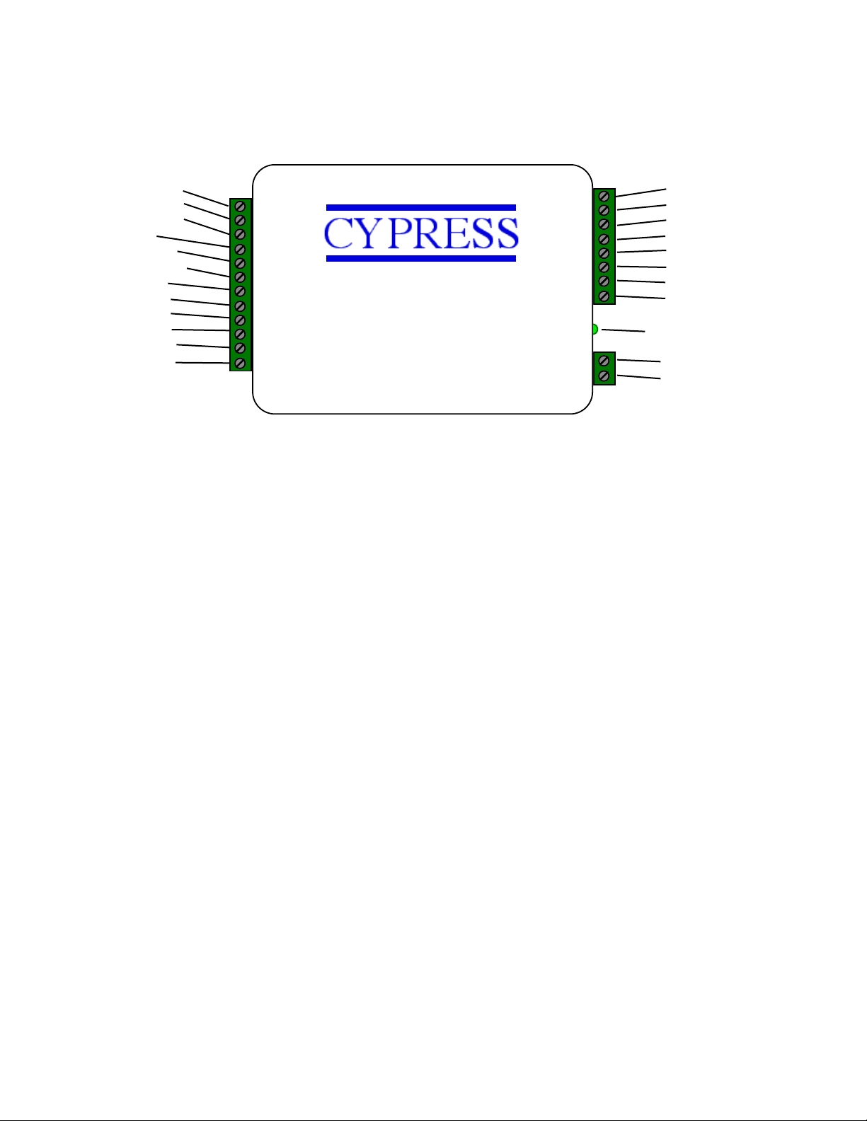
External connections and product description
Converter CVX-1300
1-D0/CLK Input
2-D1/Data Input
3-Aux2 LED Out
4-Ground
5-RS232 Input
6-RS232 Output
7-RLY1 N.C.
8-RLY1 Com
9-RLY1 N.O.
10-RLY2 N.C.
11-RLY2 Com
12-RLY2 N.O.
1-D0/CLK Output
2-D1/Data Output
3-Aux1 LED In
4-Analog In1
5-Analog In2
6-+5 VDC Out
7-RS485 (-)
8-RS485 (+)
Diagnostic LED
1-Ground
2-8 to 16 VDC In
Note: Terminals shown for reference. Connections may or may not be utilized based on
converter function.
The Cypress CVX-1468 is based on the CVX-1200 series converter. For most legacy converter
functions, the DIP switch settings will be set the same as with the Cypress CVX-1200.
This document provides a quick reference to the CVX-1468 converter connections and switch
settings. Refer to the CVX-1468 operating manual for detailed information on specific conversion
functions.
A Diagnostic LED is provided to provide operational status of the converter:
Diagnostic LED OFF - No power
Diagnostic LED Blinking Green - Unit is operating
Diagnostic LED Red - Undefined DIP Switch Setting
Page 2 of 8
Page 3

CVX-1468 Description
The CVX-1468 includes all of the CVX-1300 converter functions. Refer to the CVX-1300
manual for the operational details and settings of those functions. DIP Switch coding of the
CVX-1300 functions
(Reverse the ON and OFF positions from those given in the table).
CVX-1468 Specific Information for each additional setting:
The CVX-1468 is a specialized converter for Transcore data conversion functions.
The CVX-1468 also includes special processing of theCVX-1300 Transcore conversion that
limits repeat reads for all Transcore conversion settings. Read data is held in a compare buffer,
if a subsequent read has the same data, then the read will not be processed. The data is held
in the buffer for 5 seconds after which time the same read will be processed. New (different)
reads are always process immediately.
If the incoming serial data stream from the Transcore reader stops for 2 seconds, the buffer is
purged and any subsequent reads will be treated as a new read.
is logically opposite of those given in the CVX-1300 DIP Switch Table
Page 3 of 8
Page 4

CVX-1468 Function QuickReference
Settings specific to the CVX-1468
DIP Switch settings for the 1368 functions have changed
Old 1368 Setting (if exists) / New 1468 Setting
Setting #120
Wiegand HID40 to WPS serial
Input Wiegand 40b: XXXXFFFFFFFFFFFFBBBBBBBBBBBBBBBBXXXXXXXX
12b FC, 16b Badge
Output Serial: <STX>000000FFFFFBBBBB<ETX>
Setting #1 / Setting #121
Wiegand 33b to WPS serial
Wiegand Input = PFFFFFFFBBBBBBBBBBBBBBBBBBBBBBBBP
Serial Output = <STX>0000000FBBBBBBBB<ETX>
Facility code is decoded as 3 digit number, only last (rightmost) digit is placed into output
stream
Setting #35 / Setting #122
Same function as the CVX-1399 DIP Switch #3 ON (CVX-1399B)
Setting #86 / Setting #124 26 bit Wiegand output
Processes Transcore tags using Generic process
Processes Transcore 26 bit ASCII tags
Setting #87 / Setting #125
Processes Transcore 26 bit ASCII tags, but generates 34 bit Cardkey output.
Setting #88 / Setting #126 37 bit Wiegand output
Processes Transcore tags using Generic process
Processes Transcore 26 bit ASCII tags
Page 4 of 8
Page 5

CYPRESS
Wiring Diagram - Serial to Wiegand
CVX Terminal
DB9 Pin
Ground
5
RS232 Input
3
Ground
Data0/Clock Out
Data1/Data Out
(Typical Connections)
Data0
Data1
Access
Control
Ground
RS232 Input
Data Bender®
Panel
Connections
to Serial
Device
DB-9 Connections
Direct to PC Com Port
Ground
+8 to +16 VDC In
(-)
(+)
DC
Power
Supply
Page 5 of 8
Page 6

CYPRESS
Wiring Diagram - Wiegand to Serial
CVX Terminal
DB9 Pin
Ground
5
RS232 Input
3
RS232 Output
2
(Typcial Connections)
Card
Reader
Data0
Data1
LED
Ground
Connections
to Serial
DB-9 Connections
Direct to PC Com Port
Device
D0/Clock In
D1/Data In
LED Out
Ground
RS232 Input
RS232 Output
Data Bender®
+8 to +16 VDC In
Ground
(-)
(+)
DC
Power
Supply
Page 6 of 8
Reader Power Not Shown
Supply power to reader according to reader supplier
specifications. The CVX-1468 only requires Data and
Ground connections to the reader. (Reader power supply
and CVX board should have common ground connection.)
Page 7

Converter
Input
Output
Settings(#)
Old 1368 / New 1468
HID40
Wiegand 40
Serial WPS 16
120
SW02232
Wiegand 33
Serial WPS
1 / 121
CVX-1399B
Serial / Wiegand
26 Bit Wiegand
35 / 122
SW02231
Serial Transcore
37 Bit Wiegand Special
68 / 123
CVT-9165A
Transcore,Transcore 26
Wiegand 26
86 / 124
CVT-9165B
Transcore 26
Wiegand 34 Cardkey
87 / 125
CVT-9165A_88
Transcore/Transcore 26
37 Bit Wiegand
88 / 126
CVX-1468 Converter Setting Quick Reference
Page 7 of 8
Page 8

#
DIP SWITCH SETTING
INPUT
OUTPUT
#
12345678Interface
Format
Interface
Format
96XX
Reserved
Reserved
97XX
X
98XX
X
99XXXX
100
XXX
101
XXX
X
102
XXX
X
103
XXXXX
104
XXX
105
XXX
X
106
XXX
X
107
XXXXX
108
XXX
X
109
XXXXX
110XXXX
X
111XXXXXX
112XX
X
113XXXX
114XXXX
115XXXX
X
116XXXX
117XXXX
X
118XXXX
X
119XXXXXX
120
XXX
X
Wiegand
HID40
RS-232
WPS 16 digits
121
XXXXX
Wiegand
33b
RS-232
WPS
122
XXXXX
Wiegand/422
26 bit / Amtech
RS-232 (9600)
ASCII
123
XXXXX
X
RS-232 (9600)
Transcore
Wiegand
Special 37b
124
XXXXX
RS-232 (9600)
Transcore / 26b
Wiegand
26 bit
125
XXXXX
X
RS-232 (9600)
Transcore 26 bit
Wiegand
34 bit
126
XXXXX
X
RS-232 (9600)
Transcore
Wiegand
37 bit
127
XXXXXXX
DIP Switch Application Table
Page 8 of 8
Note: X = Switch OFF
 Loading...