

Page 1
para la naturaleza
100% papel reciclado
ist umweltfreundlich
100% Altpapier
620 SR
620 SR
& 625 MPS
& 625 MPS
N
pour la nature
papier recyclé 100%
for nature
recycled paper 100%
per la natura
M
R
E
E
T
C
A
Z
I
E
N
D
UNI EN ISO 9001-085
A
C
I
F
A
I
T
C
R
E
A
T
carta riciclata 100%
Page 2
ENGLISHENGLISH
625 MPS
DECODER
SL - SLP DS
625 MPS
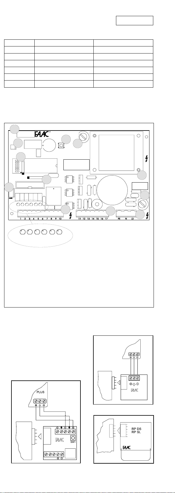
Table 4 Operation of Status LEDS
LED ON (contact closed) OFF (contact open)
FCC closing limit switch not engaged closing limit switch engaged
FCA opening limit switch not engaged opening limit switch engaged
OPEN activated deactivated
CLOSED/FSW activated (*)/saf. disengaged (**) deactivated (*)/saf. engaged (**)
STOP deactivated activated
ALARM panic contact deactivated panic contact activated
(*) P logic operation
(**) A / E logic operation
625 MPS CONTROL UNIT
J4
DECODER
J6
R
625 MPS
RESET
P1
F2
DS1
J5
J3
DL1DL5 DL2
DL6
TF1 TRANSFORMER
J1 REMOVABLE LOW-VOLTAGE TERMINAL
STRIP
J2 REMOVABLE POWER TERMINAL STRIP
J3 LIMIT SWITCH CONNECTOR
J4 DECODER CONNECTOR
J5 CONNECTOR FOR FSW, SLAVE, RELAY
BOARDS
J6 CONNECTOR FOR NTC PROBE
DL6
DL3 DL4
DL1DL5 DL2
DL3 DL4
J1
J9 REMOVABLE MAINS POWER TERMINAL
STRIP
P1 RESET PUSHBUTTON
F1 F5A FUSE (MOTOR)
F2 T1.6A FUSE (ACCESSORIES)
DS1 PROGRAMMING MICROSWITCHES
DL1 OPEN IMPULSE LED (A/E/P LOG.)
DL2 CLOSE IMPULSE LED (P LOG.)
SAFETY CONTACT (A LOG.)
DL3 STOP IMPULSE LED
DL4 ALARM LED (PANIC)
DL5 OPENING LIMIT SWITCH LED
DL6 CLOSING LIMIT SWITCH LED
J2
TF1
F1
J9
Fig. 15
5.2. CONNECTING RADIO RECEIVERS
Use quick connector J4 to insert
one of the decoder or receiver
cards RP shown in boxes A - B - C.
Fit it with the components
oriented towards the centre of
the 625 MPS card.
B
A
625 MPS
PLUS
MINIDEC
SL/DS
C
Page 3

ENGLISH ENGLISH
A / E LOGICS CONNECTIONS
ANTIPANICO
PANIC ALARM
ANTIPANIQUE
PANIKSCHUTZ
ANTIPÁNICO
STOP
12345678910 11121314 15 1617
OPEN
5
+
24 Vdc
–––+
NCFXNO
4
3
2
FX
1
24 VAC
MAX 5 W
LAMPADA SPIA
WARNING LIGHT
LAMPE TÉMOIN
KONTROLLAMPE
TESTIGO
FAAC
LAMP
+
2
1
–
VENTOLA
FAN
VENTILATEUR
LÜFTER
VENTILADOR
M
MOTOR
L
N
230 VAC +6% -10%
50 Hz
Fig. 16
P LOGIC CONNECTIONS
ANTIPANICO
PANIC ALARM
ANTIPANIQUE
PANIKSCHUTZ
ANTIPÁNICO
STOP
CLOSE
12345678910 1112131415 1617
OPEN
24 Vdc
––+
24 VAC
MAX 5 W
NC NO
LAMPADA SPIA
WARNING LIGHT
LAMPE TÉMOIN
KONTROLLAMPE
TESTIGO
FAAC
LAMP
VENTOLA
FAN
VENTILATEUR
LÜFTER
VENTILADOR
M
MOTOR
L
N
230 VAC +6% -10%
50 Hz
Fig. 17
5.3. DESCRIPTION OF TERMINAL STRIP
OPEN
This means any activating device with normally open contact,
whose activation causes the beam to perform an opening
movement. In automatic and semi-automatic logics, it
controls both opening and closing movements.
CLOSE
This
means
any activating device with normally open
contact, whose activation causes the beam to perform a
closing movement. (Present only in P logic).
STOP
This means all devices with
normally closed contact
, which
when activated stop movement of the barrier until a subsequent Open pulse is sent.
SAFETY
This
means
all devices (photocells, sensitive pneumatic
safety edges, magnetic coils) with normally closed
contact, which interrupt the movement of the beam
whenever there is an obstacle within their range.
PANIC
This
means
an activating device with normally closed
contact, which is activated in an emergency and causes
the beam to open, suspending its current status until the
RESET pushbutton is pressed.
5.4. PROGRAMMING THE MICROSWITCHES
123456
Logic SW1 SW2
AONON
E OFF ON
P ON OFF
R(*) OFF OFF
Speed OP/CL SW 6
OP=0.8 CL=2.2 ON
OP=0.8 CL=0.8 OFF
With 5 sec. pre-flashing
of warning lamp
Pause Time SW3 SW4 SW5
(sec)
Ø OFF OFF OFF
5 ON OFF OFF
10 OFFONOFF
20 ON ON OFF
10 OFF OFF ON
20 ON OFF ON
{
30 OFF O N ON
40 ON ON ON
NOTE: To obtain a duty cycle of 100%, dip switch no. 6 must be
positioned as shown in Table 5.
Table 5 BARRIER MODEL SW6
620 SR 0.8 - 2.2 ON
620 SR 0.8 - 0.8 OFF
NOTE: WHENEVER YOU CHANGE THE MICROSWITCH
PROGRAMMING, PRESS THE RESET PUSHBUTTON AFTERWARDS.
(*) IMPORTANT!: The R logic (remote) must be selected
only if there are two opposing barriers working
simultaneously. (See paragraph "624 SLAVE CARD", below.)
OPERATION OF SAFETY DEVICES
In the A or E logics, it is possible to obtain two different
types of safety device operation, depending on the pause
times that are selected:
- PAUSE TIMES WITH LAMP PRE-FLASHING (10-20-30-40 sec):
the closing movement is stopped, then reversed on
disengagement.
- PAUSE TIMES WITHOUT LAMP PRE-FLASHING:(0-5-10-20 sec):
the closing movement is reversed at once.
ALARM CONDITION
It occurs in the following cases:
1) Enabling of panic input.
2) Activation of safety TIME-OUT device, which interrupts
the operation of the system when operating time
exceeds 30 sec.
3) Simultaneous triggering of the two limit switches.
4) Microprocessor reading anomaly (syncro).
The alarm condition is indicated by the quick flashing
(0.25 sec) of the warning light (if connected).
In this condition, all the functions of the system are
disabled. Normal operation is restored only after the
cause of the alarm has been eliminated and the RESET
pushbutton has been pressed.
OPERATION WITH THE DIFFERENT CONTROL LOGICS
Table 6 A Logic (AUTOMATIC)
impulse
beam
status
closed
open in pause
closing
opening
stopped
OPEN
opens, recloses after
pause time
recloses at once (*)
reverses movement
no effect
recloses at once (*)
stops counting
STOP
no effect
stops
stops
no effect
SAFETY
no effect
freezes pause time up
to disengagement
see relevant
paragraph
no effect
no effect
Beam opens and/
or remains open.
Alarm condition is
activated
(see relevant
paragraph)
PANIC
Table 7 E Logic (SEMI-AUTOMATIC)
impulse
beam
status
closed
open
closing
opening
stopped
(*) If pre-flashing has been selected, the barrier closes after 5 sec.
OPEN
opens
recloses (*)
reverses movement
stops
recloses (*)
STOP SAFETY
no effect
stops
stops
stops
no effect
no effect
no effect
see relevant
paragraph
no effect
no effect
PANIC
Beam opens and/
or remains open.
Alarm condition is
activated
(see relevant
paragraph)
16
Page 4

Table 8 P Logic (PARKING)
(this logic does not allow pre-flashing)
impulse
beam
status
closed
open
closing
opening
stopped
OPEN
opens
no effect
reverses movement
no effect
opens
opens, recloses at
CLOSED STOP
no effect
recloses
no effect
once
recloses
no effect
no effect
stops movement
stops movement
no effect
PANIC
Beam opens and/
or remains open.
Alarm condition is
activated
(see relevant
paragraph)
Table 9 Operation of Warning Light
BEAM STATUS N.O. CONTACT (*) N.C. CONTACT (**)
closed
opening or open
pre-flashing (if selected)
and/or closing
off
on
on
off
flashing
(*) Warning light connected between terminals 8 and 10
(**) Warning light connected between terminals 9 and 10
 Loading...