

Page 1

5.1. CONNECTING THE ELECTRONIC UNIT
Important! Disconnect the power supply before you perform
any type of operation (connections, programming or
maintenance) on the electronic unit.
Warning: When terminal strip J2 is disconnected, the power
supply outputs of the motor, fan and flashing lamp are still
connected to electric power.
Follow points 10, 11, 12, 13 and 14 of the GENERAL SAFETY
REGULATIONS.
Position the pipes, as shown in Figure 3, and connect the
624 MPS electronic unit to the accessories.
Keep the power supply cables separate from the control
and safety signal ones (photocells, receiver, pushbutton,
etc.). To prevent electric interference, use separate pipes.
TAB. 4 TECHNICAL CHARACTERISTICS OF 624 MPS
POWER SUPPLY 230 V (+6 -10 %) 50 Hz
MAX. MOTOR LOAD 300 W
MAX. ACCESSORY LOAD 500 mA
MAX. WARNING LIGHT POWER 5 W (24 Vac)
TEMPERATURE RANGE - 20°C to 55°C
TAB. 5 OPERATION OF STATUS LEDS
LED ON (contact closed) OFF (contact open)
FCC closing limit switchnot engaged closing limit switch engaged
FCA opening limit switchnot engaged opening limit switch engaged
OPEN activated deactivated
CLOSED/FSW activated (*)/saf. disengaged(**) deactivated (*)/saf. engaged (**)
STOP deactivated activated
ALARM beam moving beam stationary
WARN. LIGHT see warn. light operation see warn. lightoperation
POWER motor power on motor power off
(*) P logic operation
(**) A / E logic operation
TAB 6 CURRENT DRAWN BY ACCESSORIES
ACCESSORY NOMINAL CONSUMPTION
R 31 50 mA
PLUS 433 E 20 mA
MINIDEC SL / DS 6 mA
DECODER SL / DS 20 mA / 55 mA
RP 433 ESL / EDS 12 mA / 6 mA
DIGICARD 15 mA
METALDIGIKEY 15 mA
FOTOSWITCH 90 mA
DETECTOR F4 / PS6 50 mA
MINIBEAM 70 mA
Page 2
ENGLISH
O
624 MPS CONTROL UNIT
R
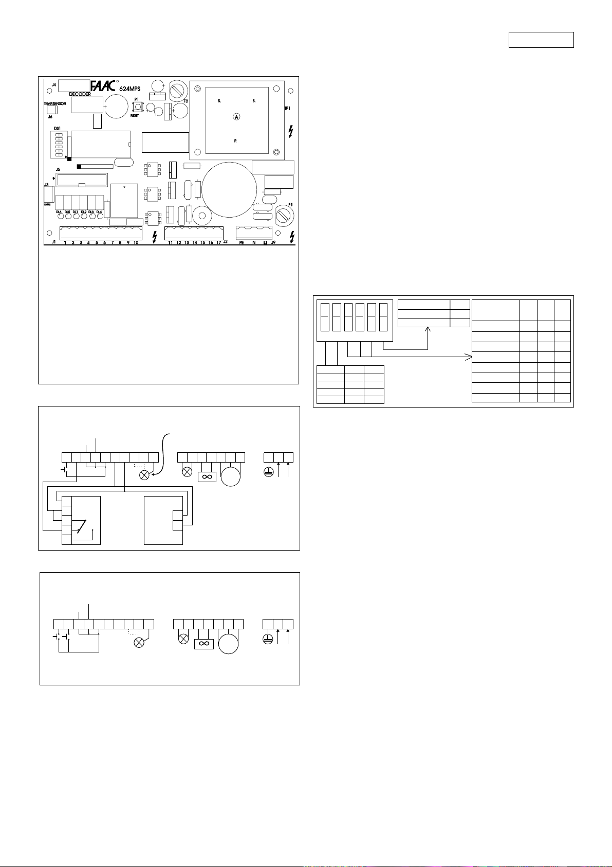
Fig. 13
TF1 TRANSFORMER.
J1 REMOVABLE LOW-VOLTAGE TERMINAL
STRIP
J2 REMOVABLE POWER TERMINAL STRIP
J3 LIMIT SWITCH CONNECTOR
J4 DECODER CONNECTOR
J5 CONNECTOR FOR FSW, SLAVE, RELAY
BOARDS
J6 CONNECTOR FOR NTC PROBE
J9 REMOVABLE TERMINAL STRIP
NETWORK POWER SUPPLY
P1 RESET PUSHBUTTON.
F1 F5A FUSE (MOTOR).
F2 T1.6 FUSE (ACCESSORIES).
DL1 OPEN IMPULSE LED (A/E/P LOG.)
DL2 CLOSE IMPULSE LED (P LOG.)
SAFETY CONTACT (A LOG.)
DL3 STOP IMPULSE LED
DL4 ALARM LED (PANIC)
DL5 OPENING LIMIT SWITCH LED
DL6 CLOSING LIMIT SWITCH LED
A / E LOGICS CONNECTIONS
ANTIPANICO
PANIC ALARM
ANTIPANIQUE
PANIKSCHUTZ
ANTIPÁNICO
STOP
OPEN NCFXNA
24 Vcc
–––+
12345678910 111213 14 15 1617
+
5
4
3
FX
2
1
24 VAC
MAX 5 W
LAMPADA SPIA
WARNING LIGHT
LAMPE TÉMOIN
KONTROLLAMPE
TESTIGO
FAAC
LAMP
2
1
VENTOLA
FAN
VENTILATEUR
LÜFTER
VENTILADOR
M
MOTOR
PE
NL1
230 VAC +6%
-10% 50-60 Hz
Fig. 14
P LOGIC CONNECTIONS
ANTIPANICO
PANIC ALARM
ANTIPANIQUE
PANIKSCHUTZ
ANTIPÁNICO
STOP
12345678910 1112 1314151617
PEN CLOSED
24 Vcc
––+
NC NA
24 VAC
MAX 5 W
LAMPADA SPIA
WARNING LIGHT
LAMPE TÉMOIN
KONTROLLAMPE
TESTIGO
FAAC
LAMP
VENTOLA
FAN
VENTILATEUR
LÜFTER
VENTILADOR
M
MOTOR
PE
NL1
230 VAC +6%
-10% 50-60 Hz
Fig. 15
DESCRIPTION OF TERMINAL STRIP
OPEN
This word indicates any activating device with normally
open contact, whose activation causes the beam to perform
an opening movement. In automatic and semi-automatic
logics, it controls both opening and closing movements.
CLOSE
This word indicates any activating device with normally
open contact, whose activation causes the beam to
perform a closing movement. (Present only in P logic).
STOP
This word indicates a activating device with normally
closed contact, whose activation suspends the current
status of the beam (opening, pause or closing), until
another pulse is sent.
SAFETY
This word indicates all devices (photocells, sensitive
pneumatic safety edges, magnetic coils) with normally
closed contact, which interrupt the movement of the
beam whenever there is an obstacle within their range.
PANIC
This word indicates a activating device with normally
closed contact, which is activated in an emergency and
causes the beam to open, suspending its current status
(open) until the RESET pushbutton is pressed.
PROGRAMMING THE MICROSWITCHES
NOTE: WHENEVER YOU CHANGE THE MICROSWITCH
PROGRAMMING, PRESS THE RESET PUSHBUTTON AFTERWARDS.
123456
Logic SW1 SW2
AONON
E OFF ON
PONOFF
R(*) OFF OFF
Deceleration SW6
short OFF
long O N
With 5 sec pre-flashing
Pausetime SW3 SW4 SW5
(sec)
Ø OFF OFF OFF
5 ON OFF OFF
10 OFF ON OFF
20 ON ON OFF
10 OFF OFF ON
20 O N OFF ON
{
30 OFF ON ON
40 ON ON ON
(*) IMPORTANT!: The R logic (remote) must be selected
only if there are two opposing barriers that work
simultaneously. (See paragraph "624 SLAVE CARD", below.)
OPERATION OF SAFETY DEVICES
In the A or E logics, it is possible to obtain two different
types of safety device operation, depending on the pause
times that are selected:
- PAUSE TIMES WITH LAMP PRE-FLASHING (10-20-30-40 sec):
the closing movement is stopped, then reversed on
disengagement.
- PAUSE TIMES WITHOUT LAMP PRE-FLASHING:(0-5-10-20 sec):
the closing movement is reversed at once.
ALARM CONDITION
It arises in the following cases:
1) Enabling of anti-panic input.
2) Activation of safety TIME-OUT device, which interrupts
the operation of the system when operating time
exceeds 30 sec.
3) Simultaneous triggering of the two limit switches.
4) Microprocessor reading anomaly (syncro).
The alarm condition is indicated by the quick flashing
(0.25 sec) of the Warning Light LED and of the warning
light (if connected).
In this condition, all the functions of the system are
disabled. Normal operation is restored only after the
cause of the alarm has been eliminated and the RESET
pushbutton has been pressed.
17
Page 3

ENGLISH
OPERATION WITH THE DIFFERENT CONTROL LOGICS
TAB. 7 A LOGIC (AUTOMATIC)
impulse
beam
status
closed
open
closing
opening
stopped
(*) If pre-flashing has been selected, the barrier closes after 5 sec.
OPEN STOP PANIC
opens, recloses after
pause time
recloses at once (*)
reverses movement
no effect
recloses at once (*)
no effect
stops counting
stops
stops
no effect
SAFETY
no effect
freezes pause time
up to
disengagement
see relevant
paragraph
no effect
no effect
Beam opens and/
or remains open.
Alarm condition is
activated
(see relevant
paragraph).
TAB.8 E LOGIC (SEMI-AUTOMATIC)
impulse
beam
status
closed
open
closing
opening
stopped
(*) If pre-flashing has been selected, the barrier closes after 5 sec.
OPEN
opens
recloses (*)
reverses movement
stops
recloses (*)
STOP SAFETY
no effect
stops
stops
stops
no effect
no effect
no effect
see relevant
paragraph
no effect
no effect
PANIC
Beam opens and/
or remains open.
Alarm condition is
activated
(see relevant
paragraph).
TAB. 9 P LOGIC (PARKING: this logic does not allow preflashing)
impulse
beam
status
closed
open
closing
opening
stopped
OPEN
opens
no effect
reverses movement
no effect
opens
opens, recloses at
CLOSED STOP
no effect
recloses
no effect
once
recloses
no effect
no effect
stops movement
stops movement
no effect
PANIC
Beam opens and/
or remains open.
Alarm condition is
activated
(see relevant
paragraph).
TAB. 10 OPERATION OF WARNING LIGHT
BEAM STATUS N.A. CONTACT (*) N.C. CONTACT (**)
closed
opening or open
pre-flashing (if selected)
and/or closing
off
on
on
off
flashing
(*) Warning light connected between terminals 8 and 10.
(**) Warning light connected between terminals 9 and 10.
 Loading...