

Page 1
624 BLD
624 BLD
Page 2

Page 3

INDEX
1. ..WARNINGS .................................................................................................................................................. 3
2. ..TECHNICAL SPECIFICATIONS ....................................................................................................................... 3
3. ..LAYOUT AND COMPONENTS OF 624BLD .....................................................................................................3
3.1 Description of components ..................................................................................................................3
4. ..ELECTRICAL CONNECTIONS ........................................................................................................................ 4
4.1 J1 Terminal-board - Accessories (Fig. 2) ........................................................................................... 4
4.2 Connection of relay photocells and safety devices with “N.C.” contact ............................................... 5
4.3 Connection of BUS photocells ............................................................................................................5
4.4 J2 Terminal-board - Motor, flashing lamp and fan (Fig. 2) ...............................................................6
4.5 J8 Connector - Motor capacitor (Fig. 2) ............................................................................................6
4.6 J9 Terminal-board - Power supply (Fig. 2) ..........................................................................................6
4.7 J3, J5 Rapid connectors - for opening and closing limit-switches (Fig. 2) ......................................... 6
4.8 J6 Connector - Beam breaking sensor (Fig. 2) ....................................................................................6
4.9 DS1 Frequency selector (Fig. 1) ...................................................................................................................... 6
4.10
J4 Connector - for Minidec, Decoder and RP ............................................................................................. 6
5. ..PROGRAMMING .......................................................................................................................................... 6
5.1 1st LEVEL PROGRAMMING ................................................................................................................... 6
5.2 Modification of the pre-setting .........................................................................................................8
5.3 Setup and BUS system control ........................................................................................................................ 8
5.4 2nd LEVEL PROGRAMMING ................................................................................................................. 9
5.5 Setup for integrated Loop Detector ................................................................................................. 10
6. ..START-UP ...................................................................................................................................................... 11
6.1 Board LEDS check ............................................................................................................................... 11
6.2 Check on BUS status ...........................................................................................................................11
7. ..AUTOMATED SYSTEM TEST ............................................................................................................................11
8. ..MASTER-SLAVE CONFIGURATIONS ............................................................................................................... 12
9. ..3rd LEVEL PROGRAMMING .......................................................................................................................... 13
9.1 Customisation of function logic..........................................................................................................15
10. PRE-SETTING VALUES ................................................................................................................................... 15
11. NOTES .........................................................................................................................................................16
12. INTERLOCK CONNECTION ...........................................................................................................................16
13. FUNCTION LOGIC TABLES ............................................................................................................................17
ENGLISH
1
Page 4

CE DECLARATION OF CONFORMITY
Manufacturer: FAAC S.p.A.
Address: Via Calari, 10 - 40069 Zola Predosa BOLOGNA - ITALY
Declares that: 624BLD control unit
2006/95/EC Low Voltage Directive
2004/108/EC Electromagnetic Compatibility Directive
Additional note:
This product underwent tests in a typical uniform configuration
(all products manufactured by FAAC S.p.A.).
ENGLISH
The Managing Director
A. Marcellan
• conforms to the essential safety requirements of the following EEC directives
Bologna, 01 January 2010
WARNINGS FOR THE INSTALLER
GENERAL SAFETY OBLIGATIONS
1) ATTENTION! To ensure the safety of people, it is important that you read
all the following instructions. Incorrect installation or incorrect use of
the product could cause serious harm to people.
2) Carefully read the instructions before beginning to install the product.
3) Do not leave packing materials (plastic, polystyrene, etc.) within reach
of children as such materials are potential sources of danger.
4) Store these instructions for future reference.
5) This product was designed and built strictly for the use indicated in this
documentation. Any other use, not expressly indicated here, could
compromise the good condition/operation of the product and/or be
a source of danger.
6) FAAC declines all liability caused by improper use or use other than that
for which the automated system was intended.
7) Do not install the equipment in an explosive atmosphere: the presence
of inflammable gas or fumes is a serious danger to safety.
8) The mechanical parts must conform to the provisions of Standards EN
12604 and EN 12605.
For non-EU countries, to obtain an adequate level of safety, the Stand-
ards mentioned above must be observed, in addition to national legal
regulations.
9) FAAC is not responsible for failure to observe Good Technique in the
construction of the closing elements to be motorised, or for any deformation that may occur during use.
10) The installation must conform to Standards EN 12453 and EN 12445.
For non-EU countries, to obtain an adequate level of safety, the Stand-
ards mentioned above must be observed, in addition to national legal
regulations.
11) Before attempting any job on the system, cut out electrical power.
12) The mains power supply of the automated system must be fitted with an
all-pole switch with contact opening distance of 3 mm or greater. Use
of a 6A thermal breaker with all-pole circuit break is recommended.
13) Make sure that a differential switch with threshold of 0.03 A is fitted
upstream of the system.
14) Make sure that the earthing system is perfectly constructed and connect metal parts of the closure to it.
15) The automated system is supplied with an intrinsic anti-crushing safety
device consisting of a torque control. Nevertheless, its tripping threshold must be checked as specified in the Standards indicated at point
10.
16) The safety devices (EN 12978 standard) protect any danger areas
against mechanical movement Risks, such as crushing, dragging, and
shearing.
17) Use of at least one indicator-light (e.g. FAACLIGHT ) is recommended
for every system, as well as a warning sign adequately secured to the
frame structure, in addition to the devices mentioned at point “16”.
18) FAAC declines all liability as concerns safety and efficient operation of
the automated system, if system components not produced by FAAC
are used.
19) For maintenance, strictly use original parts by FAAC.
20) Do not in any way modify the components of the automated system.
21) The installer shall supply all information concerning manual operation
of the system in case of an emergency and shall hand over to the user
the warnings handbook supplied with the product.
22) Do not allow children or adults to stay near the product while it is
operating.
23) Keep remote controls or other pulse generators away from children,
to prevent the automated system from being activated involuntarily.
24) Transit is permitted only when the automated system is idle.
25) The user must not attempt any kind of repair or direct action whatever
and contact qualified personnel only.
26) Check at least every 6 months the efficiency of the system, particularly
the efficiency of the safety devices (including, where foreseen, the
operator thrust force) and of the release devices.
27) Anything not expressly specified in these instructions is not permitted.
2
Page 5
CONTROL UNIT 624 BLD
1. WARNINGS
Attention: Before attempting any work on the control unit (connections, maintenance), always turn off power.
- Install, upstream of the system, a differential thermal breaker with adequate tripping threshold.
- Connect the earth cable to the terminal on the J9 connector of the unit (see fig.2).
- Always separate power cables from control and safety cables (push-button, receiver, photocells, etc.). To avoid any electrical
noise, use separate sheaths or a screened cable (with the screen earthed)
.
2. TECHNICAL SPECIFICATIONS
Power supply
voltage *
Absorbed power
Motor max. load
Power supply
for accessories
Accessories max.
current
Operating ambient
temperature
Protection
fuses *
Work time
Pause time
Motor power
Programming
Rapid connector
Programmable
outputs
Features
230 V~ (+6% -10%) - 50/60 Hz
115 V
or
~
(+6% -10%) - 50/60 Hz
7 W
1000 W
24 Vdc
500 mA
from -20°C to +55°C
F1 = F 10A - 250V F2 = T 0,8A - 250V
or
F1 = F 20A - 120V F2 = T 0,8A - 120V
Programmable (from 0 to 4 minutes)
Programmable (from 0 to 4 minutes)
Programmable on 50 levels
3 programming levels for greater
flexibility of use
Coupling for 5-pin Minidec board,
Decoder, Receiver RP/RP2
4 programmable outputs
in 18 different functions
Management of slow-downs,
multifunction display, BUS technology
and INTEGRATED METALLIC MASS
DETECTOR
* The power supply voltage and fuses depend on the version
purchased
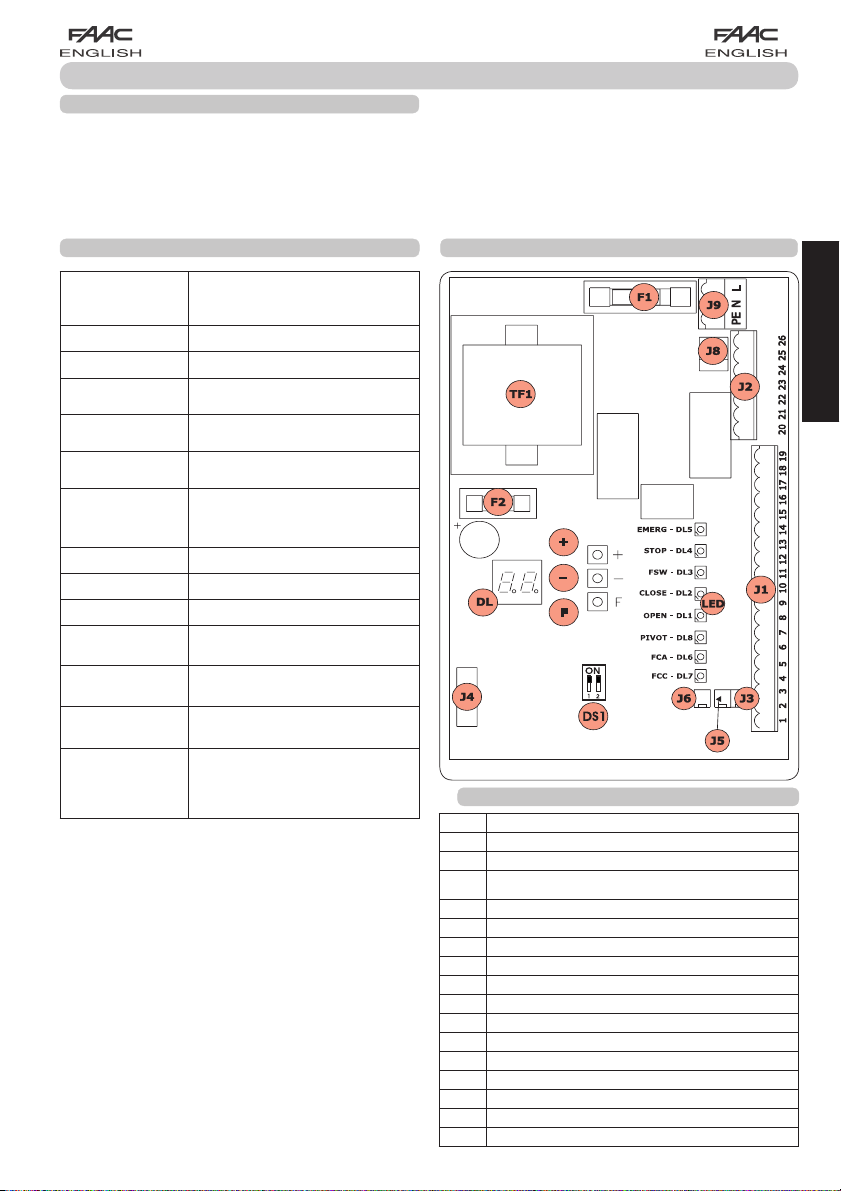
3. LAYOUT AND COMPONENTS OF 624BLD
3.1 DESCRIPTION OF COMPONENTS
DL SIGNALS AND PROGRAMMING DISPLAY
LED INPUT STATUS CONTROL LEDs
J1 LOW-VOLTAGE TERMINAL BOARD
TERMINAL BOARD FOR CONNECTION OF MOTOR, FLASHING
J2
LAMP AND FAN
J3 OPENING LIMIT-SWITCH CONNECTOR
J4 CONNECTOR FOR DECODER MINIDEC / RP RECEIVER
J5 CLOSING LIMIT-SWITCH CONNECTOR
J6 CONNECTOR FOR ROD BREAKING SENSOR
J8 CONNECTOR FOR MOTOR THRUST CAPACITOR
J9 TERMINAL-BOARD FOR 230 VAC POWER SUPPLY
DS1 LOOP 1 and LOOP 2 FREQUENCIES SELECTOR
F1
FUSE FOR MOTORS AND TRANSFORMER PRIMARY WINDING (F 5A)
F2 FUSE FOR LOW VOLTAGE AND ACCESSORIES (T 800mA)
F PROGRAMMING PUSH-BUTTON “F”
+ PROGRAMMING PUSH-BUTTON “+”
- PROGRAMMING PUSH-BUTTON “-”
TF1 TRANSFORMER
3
ENGLISH
Fig. 1
Page 6
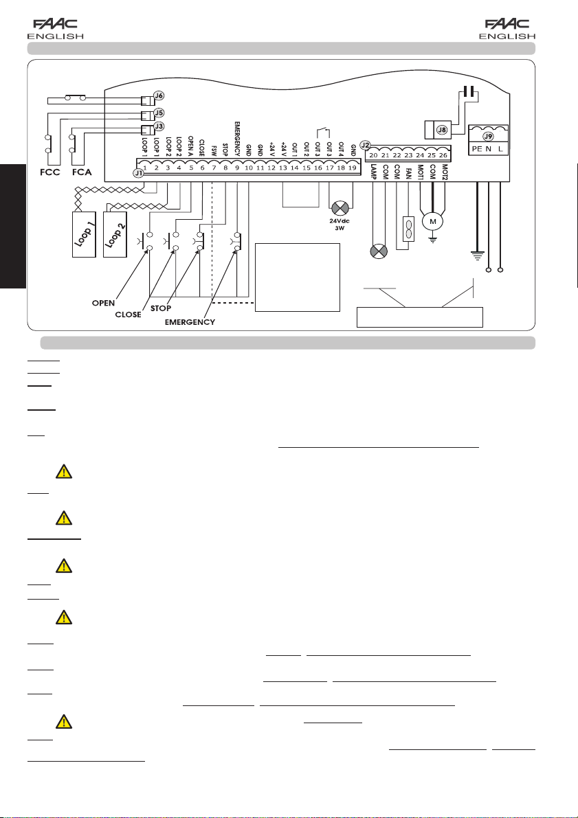
4. ELECTRICAL CONNECTIONS
BEAM
BREAKER
ENGLISH
4.1. J1 TERMINAL-BOARD - ACCESSORIES (FIG. 2)
To connect the
photocells and
safety devices,
consult paragraph
4.2.
MOTOR THRUST
CAPACITOR
BLUE
MOTOR
FAN
230 V~
or 115 V~
*
60W max
* 230 V~ board version
or 115 V~ board version
230 V~
or 115 V~
50/60 Hz
Fig. 2
*
LOOP 1 - Magnetic loop LOOP 1 (OPEN - terminals 1-2): it activates the OPENING function
LOOP 2 - Magnetic loop LOOP 2 (SAFETY/CLOSE - terminals 3-4): it activates the SAFETY/CLOSING function
OPEN - “Opening” Command (N.O. - terminal 5): this refers to any pulse generator ( e.g.: push-button) which, by closing
a contact, commands the barrier to close and/or open.
CLOSE - “Closing” Command (N.O. - terminal 6): this refers to any pulse generator (e.g.: push-button) which, by closing
a contact, commands the barrier to close.
FSW - Closing safety-devices contact (N.C. - terminal 7). The purpose of the closing safety devices is to protect the
barrier movement area during closure, by reversing motion. They are never tripped during the opening cycle. If the closing
Safety devices are engaged when the automated system is in open status, they prevent the closing movement.
If closing safety devices are not connected, jumper connect the FSW and GND terminals (fig. 6).
STOP - STOP contact (N.C. - terminal 8): this refers to any device (e.g.: push-button) which, by opening a contact, can
stop the motion of the automated system.
If stop safety devices are not connected, jumper connect the STOP and GND terminals (fig. 6).
EMERGENCY - EMERGENCY contact (N.C- terminal 9): this refers to any switch which, by being activated in emergency
state, opens the barrier and stops its movement until the contact is restored
If emergency safety devices are not connected, jumper connect the EMERGENCY and GND terminals (fig. 6).
.
GND ( terminals 10-11-19) - Negative contact for feeding accessories
24 Vdc ( terminals 12-13)- Positive contact for feeding accessories
Max. load of accessories: 500 mA. To calculate absorption values, refer to the instructions for individual
accessories
OUT 1 - Output 1 GND open-collector (terminal 14): The output can be set in one of the functions described in the
2nd programming level (see par. 5.2.). Default value is FAILSAFE. Maximum load: 24 Vdc with 100 mA.
OUT 2 - Output 2 GND open-collector (terminal 15): The output can be set in one of the functions described in the
2nd programming level(see par. 5.2.). Default value is CLOSED beam. Maximum load: 24 Vdc with 100 mA.
OUT 3 - RELAY Output 3 (terminal 16-17): The output can be set in one of the functions described in the 2nd programming
level (see par. 5.2.). Default value is INDICATOR LIGHT: Maximum load: 24 Vdc or Vac with 500 mA.
To avoid endangering correct operation of the system, do not exceed the indicated power indicated in fig. 2.
OUT 4 - Output 4 open-collector +24Vdc (terminal 18): The output can be set in one of the functions described in the
2nd programming level (see par. 5.2.). The default value for ALL THE PRE-SETTINGS is BUS COMMUNICATION. Maximum
load: 24 Vdc with 100 mA.
4
Page 7
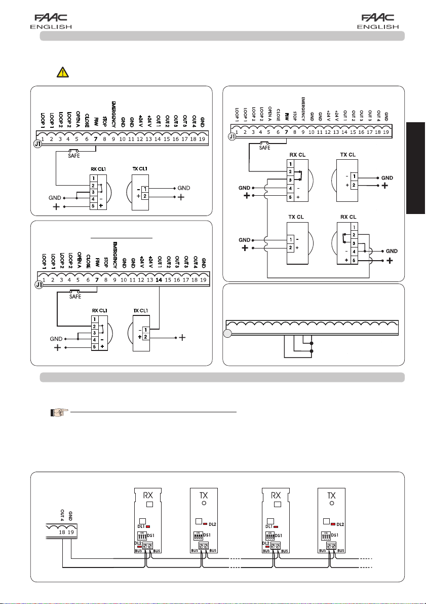
4.2.CONNECTION OF RELAY PHOTOCELLS AND SAFETY DEVICES WITH “N.C.” CONTACT
The 624 BLD board envisages the connection of closing safety devices which are tripped only during the barrier closing
movement, and are therefore suitable for protecting the closing zone against the risk of impact.
If two or more safety devices (NC contacts) have to be connected, put them in series with each other as
shown in figures 3, 4, 5 under the heading “SAFE”.
Connection of 1 pair of closure photocells
Connection of 2 pairs of closure photocells
Fig. 3
ENGLISH
Connection of 1 pair of closure photocells
with FAIL SAFE facility
Fig. 5
CLOSE
FSW
STOP
EMERGENCY
GND
GND
OUT 3
OUT 3
OUT 1
OUT 2
+24 V
+24 V
OUT 4
GND
191816 17151412 1310 11896745231
Fig. 6
Fig. 4
To be set in the 2nd programming level : FS = Y and o1= 00
Connection of no safety device
OPEN A
LOOP 2
LOOP 2
LOOP 1
LOOP 1
J1
4.3.CONNECTION OF BUS PHOTOCELLS
Photocells using BUS technology are connected to the 624 BLD control unit ALL IN PARALLEL as shown in Fig. 7 through
single power/communication line.
The BUS photocells do not have connection polarity.
Up to a maximum of 8 pairs of BUS photocells can be connected to the board.
The photocells are subdivided by quantity into the following groups:
Pairs of closure photocells: max 7
Pairs of photocells for OPEN pulse: max 1
Make sure that at the 2nd
programming level
:
1st Pair of photocells 2nd Pair of photocells
o4 = 00 and P4 = no
Fig. 7
5
Page 8
624BLD
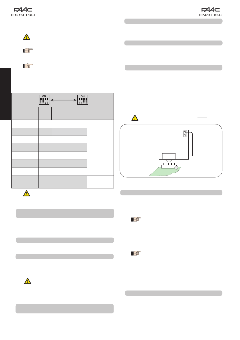
After positioning of the BUS technology photocells, select
the address of each pair through the combination of the
DIP-SWITCHES present on each photocell.
Table 4 shows the programming of the dip-switches present
within the transmitter and receiver of the BUS photocells.
Tab. 4 - Address of PAIRS of BUS photocells
ENGLISH
Set THE SAME DIP-SWITCH ADDRESS
chosen on both the transmitter and the
receiver of the same pair.
Make sure that there are not two or
more pairs of photocells with the same
address
If no BUS accessory is used, leave terminals
18 and 19 free
DIP-SWITCH
TX
Dip1 Dip2 Dip3 Dip4
.
SAME
ADDRESS
Pair
number
DIP-SWITCH
RX
Type
ON OFF OFF OFF 1st pair
ON OFF OFF ON 2nd pair
ON OFF ON OFF 3rd pair
ON OFF ON ON 4th pair
CLOSURE
Photocells
ON ON OFF OFF 5th pair
ON ON OFF ON 6th pair
ON ON ON OFF 7th pair
ON ON ON ON
To make the installed Bus accessories
operational, perform on-board
memorisation as explained in chapter
5.3.
4.4. J2 TERMINAL-BOARD - MOTOR, FLASHING LAMP
AND FAN (FIG. 2)
Single
Pair
OPEN
PULSE
M (COM-MOT1-MOT2): Motor Connection
LAMP (LAMP-COM): Flashing lamp output
FAN (FAN-COM): Fan output
4.5. J8 CONNECTOR - MOTOR CAPACITOR (FIG. 2)
Rapid connector for connecting the motor thrust capacitor.
4.6. J9 TERMINAL-BOARD - POWER SUPPLY (FIG. 2)
PE : Earth connection
N : Power supply 230 V~ or 115 V~( Neutral )
L : Power supply 230 V~ or 115 V~( Line )
For correct operation, the board must
be connected to the earthing conductor
present in the system. Install, upstream
of the system, a differential thermal
breaker.
4.7. J3, J5 RAPID CONNECTORS - FOR OPENING AND
CLOSING LIMIT-SWITCHES (FIG. 2)
Quick-fit connector for connection of the opening (J3) and
closing (J5) limit-switches.
4.8. J6 CONNECTOR - BEAM BREAKING SENSOR (FIG. 2)
Quick-fit connector for connecting the beam breaking sensor
(where present). If this sensor is absent, leave the supplied
jumper in place.
4.9. DS1 FREQUENCY SELECTOR (FIG. 1)
DIP-SWITCH selector used to set a HIGH or LOW working
frequency of the vehicle loop detectors. Consult chapter
.
5.5
4.10. J4 CONNECTOR - FOR MINIDEC, DECODER AND RP
It is used for rapid connection of Minidec, Decoder and RP/
RP2 Receivers.
If you are using an RP2 twin-channel receiver, you will be able
to directly command the automated system’s OPEN and
CLOSE from a twin-channel radio control.
If using a single-channel RP type receiver, only OPEN can be
commanded.
Fit the accessory with the component side directed toward
the board interior
.
Insert and remove the boards ONLY after
cutting power.
An example of a radio accessory connection
RP / RP2
J4
Fig. 8
5. PROGRAMMING
To programme the operation of the automated system, the
“PROGRAMMING” mode must be accessed.
Programming is in three parts: 1st LEVEL, 2nd LEVEL and 3rd
LEVEL.
modification of the programming
parameters is immediately effective,
whereas definitive memory-storage occurs
only on exiting programming and returning
to the view of the automated system status.
If you cut power to the unit before returning
to view the status, all the modifications made
will be lost.
You can return to viewing the status from
any point of programming at any level, by
pressing keys F and - simultaneously.
5.1. 1ST LEVEL PROGRAMMING
To access 1st LEVEL PROGRAMMING, use push-button F:
• if you press it (and hold it down), the display shows the
name of the first function.
• if you release the push-button, the display shows the
value of the function, which can be changed with keys
+ and -.
6
Page 9

• if you press F again (and hold it down), the display shows
the name of the next function, etc.
• when you reach the last function, press the push-button
F to exit programming, and the display resumes showing
the inputs status.
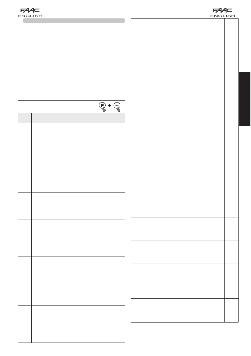
1ST LEVEL PROGRAMMING
Display Function Default
LOADING PARAMETERS:
00
dF
bu
LO
Neutral condition
0 1
Default FAAC 1 loaded
02
Default RESERVED FOR FAAC
03
Default FAAC CITY loaded
04
Default FAAC CITY K loaded
05
Default J275 loaded
06
Default J275K loaded
00
LEAVE AT
CHANGE TO THE PROGRAMMING.
For an explanation of the dF parameter
refer to page 8 chapter 5.2.
BUS ACCESSORY MENU
For an explanation of this parameter refer to
page 8 chapter 5.3.
FUNCTION LOGICS:
A
IF YOU DO NOT WISH TO MAKE ANY
Automatic
A1 Automatic 1
00
E
E Semiautomatic
P Parking
PA Parking automatic
Cn Condo
CA Condo automatic
rb Faac-City ( traffic bollard logic )
C Dead-man
r Remote
Cu Custom
PAUSE TIME:
This operates only if an automatic
PA
logic was selected. Can be adjusted
from
0 to 59 sec. in 1 second steps.
Subsequently, the display changes to
show minutes and tenths of a second
(separated by a dot) and time is adjusted
in 10 second steps, up to the maximum
value of
4.1 minutes.
e.g. if the display shows
time will be 2 min and 50 sec
POWER:
Adjusts motor power.
FO
01
LOOP 1:
If this function is enabled, the loop
L1
connected to the Loop1 input will have
the OPEN function.
Y = loop1 active
no = loop1 not active
Attention: if the function is not enabled,
loop1 status will nevertheless be available
on one of the outputs, if appropriately set
(see second level programming).
= minimum power
50
= maximum power
2.5, the pause
.
20
50
no
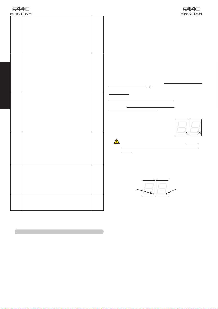
Display Function Default
LOOP 2
L2
H1
H2
S1
S2
St
The display of the automated system status
7
:
If this function is enabled, the loop
connected to Loop2 input will have the
SAFETY/CLOSE function, i.e. it will operate
as SAFETY during the closing stage, and
will command CLOSE to the board at
release.
Y =
no
Attention: if the function is not enabled,
loop2 status will nevertheless be available
on one of the outputs, if appropriately
set.
BOOST LOOP 1 FUNCTION
loop2 active
= loop2 not active
Y = Active no = Not active
Thanks to this function you can increase
the sensitivity level at the moment of
detection. When the vehicle leaves the
loop, the sensitivity returns to the selected
level. This system holds the detection
contact even in the event of very high
vehicles as well as during the passage of
a tractor with trailer.
BOOST LOOP 2 FUNCTION
Y = Active no = Not active
See BOOST LOOP1 function.
SENSITIVITY LOOP 1
Regulates the sensitivity of the loop:
01
SENSITIVITY LOOP 2
Regulates the sensitivity of the loop:
AUTOMATED SYSTEM STATUS
Exit programming,
memory storage of data set and return to
automated system status view
00
01
02
03
04
05
06
07
08
09
10
fundamental importance for the operator assigned
to installation/maintenance, to distinguish the logical
processes the board performs during movements.
If, for example, the automated system is in CLOSED
state
the command OPEN, the display will change to
01
, if pre-flashing is enabled, or directly to 02
(the OPENING movement), to then display
reaching the OPEN position.
= minimum
10
= maximum
01
= minimum
10
= maximum
:
.
Closed
Opening pre-flashing
Opening
Open
In pause
Closing pre-flashing
Closing
Stopped ready to close
Stopped ready to open
Emergency opening
Closing safety device in operation
00
must be shown on the display. On reaching
St
03
no
no
ENGLISH
no
05
05
is of
on
Page 10

Example of sequence of states displayed starting from barrier
closed:
00 Closed
02 Opening
03 Open
04 Pause (if present)
ENGLISH
In the sequence, states 01 and 05 are not shown; these
correspond to pre-flashing at opening and at closing,
respectively.
5.2. MODIFICATION OF THE PRE-SETTING
The modification of the dF parameter enables you to
automatically load 6 different configurations modifying all
programming values at every level with preset values.
This possibility is a convenient starting point for subsequent
rapid ‘fine tuning’ of the 624 BLD for functioning with 6
different types of installation.
6 PRE-SETTINGS may be selected:
01
Default FAAC for barriers
02
Default RESERVED FOR FAAC
03
Default for the FAAC CITY 275 H600 and H800 range
04
Default for FAAC CITY 275 H700 K
05
Default for J275
06
Default for J275K
To implement loading of the values of one of the 6
pre-settings, select the required pre-setting
04
, 05 , 06 ) and exit 1st level programming.
EXAMPLE: selecting 01 and exiting 1st level programming, all
the FAAC default values which can be found in the 1st, 2nd
and 3rd level tables in the “Default” column are loaded. The
624 BLD is therefore configured for movement of a barrier.
THE LOADING OF A PRE-SETTING CANCELS ALL
THE MODIFICATIONS PREVIOUSLY MADE AT ANY
PROGRAMMING STEP. IF YOU DO NOT WISH TO
LOAD ANY PRE-SETTING, LEAVE THE
AT
00
.
The
It is therefore not possible to identify what pre-setting was
previously set.
If you do not wish to load any pre-setting, ALWAYS leave
the
dF
step at value 00 and move on to the following
programming step.
Ensure that you load the desired default and
exit 1st level programming BEFORE modifying
other steps, in order to avoid deleting all the
modifications made.
To learn more about the specifications of each pre-setting,
refer to chapter 10 on page 15.
dF
, step, unlike the others, does not store
the value selected but returns to show
again, as standard condition.
06 Closing
( 01,
02 , 03
dF
STEP
00
5.3. SETUP and BUS SYSTEM CONTROL
Each time you install one or more BUS accessories (as
explained in chapter 4.3) these must be stored on the
board.
Storage is performed as follows:
- enter the first programming level as explained in chapter.
5.1;
- at the
The display shows
the standard condition indicated in fig. 10. The storage
procedure is finished.
The bu programming step also has the function of displaying
the status of the BUS technology accessories. Figure 9
indicates the exact correspondence between the segments
of the display and the inputs.
Segment ON = closed contact
Segment OFF = open contact
The configuration for correct operation of
the automated system should show the three
horizontal segments ON as in figure 10.
In case of engagement of the closure photocells,
the upper and lower segments switch off, leaving
the central segment on, as in figure 11.
In case of engagement of the PULSE GENERATOR
OPEN pair, the corresponding vertical segment
,
switches on for the engagement time of the pair,
as illustrated in figure 12.
The PULSE GENERATOR OPEN pair of photocells, if engaged,
commands opening of the application and prevents its
closure until it is released.
The BUS communication system uses a self-diagnostic function
able to supply reports of incorrect connection or of erroneous
configuration of the BUS accessories.
The display shows the cc signal FLASHING
when a SHORT-CIRCUIT is present along
the BUS line, as in figure 13. Check the
connections made (chapter.4.3).
The display shows the
FLASHING, as in figure 14, if more than
one pair of photocells should have the
same address.
In this latter case, check all the addresses set on all the
photocells installed, referring to chapter 4.3.
bu
push-button F and press push-button + for 1 second.
programming step, release programming
--
for an instant and then returns to
FSW CL = BUS photocells
closing
OPEN = BUS photocell
NOT USED
If no pair of BUS photocells is present on the
system, the
show the display in figure 10.
pulse generators OPEN
Fig. 10
Fig. 11
Fig. 12
bu
programming step will still
Fig. 13
Fig. 9
Er message
Fig. 14
8
Page 11
5.4. 2nd LEVEL PROGRAMMING
To access 2nd LEVEL PROGRAMMING, press push-button F
and, while holding it down, press push-button +:
• if you release the + push-button, the display shows the
name of the first function.
• if you also release the F push-button, the display shows the
value of the function, which can be changed with keys +
and -.
• if you press the F key (and hold it down), the display shows
the name of the next function; if you release it, the value
is shown and can be modified with keys + and -.
• when you reach the last function, press push-button F to
exit programming, and the display resumes showing the
inputs status.
2ND LEVEL PROGRAMMING
Display
Function
MAXIMUM THRUST TORQUE:
bo
the motor runs at maximum torque (ignoring
torque regulation) at the initial moment of
movement.
Y = Active
no = Excluded
PRE-FLASHING:
PF
it permits activation of the flashing lamp for 5
secs before the start of movement.
no excluded
OC before each movement
PA at end of pause only
CL before closing
SLOW CLOSING:
SC
for setting the entire closing stage at slow
speed.
Y = Active
no = Excluded
DECELERATION TIME AFTER LIMIT SWITCHES:
tr
for setting the deceleration time (in seconds)
after the opening and closing limit switches
have operated.
Can be adjusted from 0 to 10 sec. in 1 second
steps.
00 = deceleration excluded
10 = maximum deceleration
WORK TIME (time-out):
t
A value should be set from 5 to 10 seconds
longer than the time required for the automated
system to move from the closed position to the
open position, and vice-versa.
Can be adjusted from
steps.
Subsequently, the display changes to show
minutes and tenths of a second (separated by
a dot) and time is adjusted in 10 second steps,
up to the maximum value of 4.1 minutes.
FAIL SAFE:
FS
If this function is activated, it enables a function
test of the photocells before any automated
system movement, independently of the
output used. If the test fails, the automated
system does not start the movement.
Y = Active
no = Excluded
0
to 59 sec. in 1 second
De-
fault
Y
no
no
03
20
no
OUTPUT 1:
o1
The output can be set to one of the following
functions:
00
00 FAILSAFE
01 INDICATOR LIGHT (lighted at
opening and pause, flashing at
closing and off when automated
system closed).
02 BEAM LIGHTING (output active
with beam closed and on pause,
inactive with beam open, flashing
during movement)
03 beam CLOSED
04 beam OPEN or in PAUSE, it goes off
during closing pre-flashing.
05 beam MOVING AT OPENING,
pre-flashing included.
06 beam MOVING AT CLOSING, pre-
flashing included.
07 beam STILL
ENGLISH
08 beam in EMERGENCY status
09 LOOP1 engaged
10 LOOP2 engaged
1 1 OPEN for 624 SLAVE
12 CLOSE for 624 SLAVE
13 beam DETACHED
14 bollard lights
15 bollard buzzer
16 FCA engaged
17 FCC engaged
18 interlock
OUTPUT 1 POLARITY:
P1
For configuring the output polarity status.
Y = N.C. polarity
no = N.O. polarity
Note: if the output is set to FAIL-SAFE (
leave the default value
OUTPUT 2:
o2
See output 1
OUTPUT 2 POLARITY:
P2
See output 1 polarity
OUTPUT 3:
o3
See output 1
OUTPUT 3 POLARITY:
P3
See output 1 polarity
OUTPUT 4 / BUS:
o4
If set at
00 the output is dedicated to
accessories with BUS technology. Refer to
chapter 4.3 on page 5 for an explanation.
This output retains the possibility of
configuration of output 1 with the exception
of functions
no effect.
OUTPUT 4 POLARITY:
P4
For configuring the output polarity status.
9
11, 12 which in this case have
Y = N.C. polarity
no = = N.O. polarity (for BUS)
no.
no
00 )
03
no
01
no
00
no
Page 12
ASSISTANCE REQUEST (coupled to the next
AS
two functions):
If activated at the end of the count-down
(settable with the next two functions under
“Cycle programming”), it activates LAMP
output for 4 sec every 30 sec. (assistance
request). Can be useful for setting scheduled
maintenance.
Y = Active
no = Excluded
CYCLE PROGRAMMING IN THOUSANDS:
nc
For setting a count-down of the system
operating cycles, settable value from 0 to 99
(thousands of cycles). The displayed value is
reset as the cycles progress, interacting with
the
nC value (99 nc decrementing steps
correspond to one
The function can be used combined with nC,
to check the use of the system and to make
use of the “Assistance request”.
CYCLE PROGRAMMING IN HUNDREDS OF
ENGLISH
nC
THOUSANDS:
For setting a count-down of the system
operating cycles, settable value from 0 to
99 (hundreds of thousands of cycles). The
displayed value is reset as the cycles progress,
interacting with the
corresponds to 99 nC decrementing steps).
The function can be used combined with
to check the use of the system and to make
use of the “Assistance request”.
HOLD TIME LOOP 1
h1
For setting the presence time on loop 1. At
the end of this time the board calibrates itself
and indicates “loop free” (decimal point of
the units OFF). On switching on the board, an
automatic reset is performed.
Y = 5 minutes
HOLD TIME LOOP 2
h2
For setting the presence time on loop 2. At
the end of this time, the board calibrates itself
and indicates “loop free” (decimal point of
the tens OFF). On switching on the board, an
automatic reset is performed.
AUTOMATED SYSTEM STATUS:
St
Exit programming, memory storage of
data and return to gate status display (see
paragraph 5.1.).
nC decrement).
nc. (1 nc decrement
no = infinite
Y = 5 minutes
no = infinite
nc,
Connection:
no
Connect the loop detectors as indicated in figure 2 on page
4:
- Terminals 1 - 2 for LOOP 1 = loop with opening function;
- Terminals 3 - 4 for LOOP 2 = loop with closing and/or closing
safety function.
To learn more about the effect of signals originating from the
loops on the automated system, please refer to the logic
tables in chapter 12.
00
To enable the function of the connected loops, enter the
1st programming level and set steps
enable the function of the connected loops, enter the 1st
programming level and set steps.
The operating status of the loop detector is shown through the
use of decimal points on the display when automated system
status is displayed (step
CALIBRATION
Each time the 624 BLD board is powered,
01
the display shows the automated system
status and the integrated loop detector
calibrates the connected loops. Therefore,
perform a calibration, removing power from
the 624 BLD for at least 5 seconds.
Calibration is shown on the display through
flashing of the two points, as in figure 15.
no
no
If one or both the magnetic loops are not installed,
the loop detector is continually calibrated without
this creating problems to the functioning of the
board. Therefore, during display of the automated
system status, one or both the decimal points will
flash constantly.
Once calibration has taken place, the decimal points indicate
the loop status:
St ).
Fig. 15
LOOP 1
Point ON = Loop ENGAGED
Point OFF = Loop DISENGAGED
Point FLASHING =
Loop NOT CONNECTED or BEING CALIBRATED
L1 and L2 in Y. To
LOOP 2
5.5. SETUP FOR INTEGRATED LOOP DETECTOR
The 624 BLD is equipped with an integrated metallic mass
detector for induction detection of vehicles.
Features:
galvanic separation between the electronics of the detector
•
and of the loop
automatic alignment of the system immediately after
•
activation
continual resetting of frequency drifts
•
sensitivity independent of loop inductivity
•
regulation of the working frequency of the loops
•
message of loop engaged with LED display
•
loop status addressable on the OUT 1, OUT 2, OUT 3 and
•
OUT 4 outputs
REGULATION OF SENSITIVITY
Regulating the sensitivity determines the variation of the
inductivity, for each channel, which a vehicle must cause to
activate the relative output of the detector.
Regulation of sensitivity is performed separately for each
channel with the aid of the two
the 1st programming level. You can also activate the BOOST
function for both detectors. Consult chapter 5.1.
REGULATION OF HOLD TIME
The retaining time count starts on engagement of the loop.
If, on expiry of this time, the loop is still engaged, a new
calibration is performed automatically where the presence
of the metallic mass on the loop no longer causes its
engagement. At the end of the new calibration, the loop is
considered “disengaged”.
The retaining time can be regulated with the aid of the two
h1and h2 parameters at the 2nd programming level.
10
S1 and S2 parameters at
Page 13
Consult chapter 5.4
FREQUENCY REGULATION and NEW BALANCING
The working frequency of each of the detector channels can
be regulated at two levels with the aid of the DS1 DIP- switch
(see fig.1).
DIP 1 ON = Loop 1 frequency LOW
OFF= Loop 1 frequency HIGH
DIP 2 ON = Loop 2 frequency LOW
OFF= Loop 2 frequency HIGH
On changing one of these DIPs, it is recommended that a
new calibration be performed. In case of installation of two
loops, select different frequencies for each loop.
NOTES FOR CONSTRUCTION OF THE LOOPS
The loop must be located at least 15 cm. from fixed metal
objects, at least 50 cm. from moving metal objects and not
more than 5 cm. from the road surface.
Use a normal single-core cable with a section of 1.5 mm²
(if the cable is buried directly, it must be double insulated).
Construct a loop, preferably square or rectangular, preparing a
PVC cable duct or making a track in the flooring as indicated
in figure 16 (the angles must be cut at 45° to avoid cable
breakage). Place the cable, performing the number of
windings indicated in the table. The two ends of the cable must
be intertwined (at least 20 times per metre) from the loop to the
detector. Avoid any cable splicing (if it should be necessar y,
solder the wires and seal the junction with a thermo-shrinking
6. START-UP
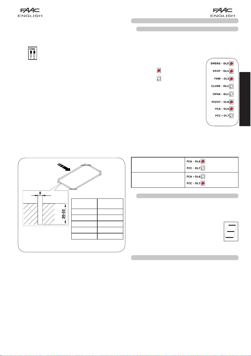
6.1. BOARD LEDS CHECK
sheath) and keep it separate from power supply lines.
Before the definitive start-up of the 624 BLD unit, control the
activation status of the LEDs present.
These LEDs indicate the status of the board inputs and have
particular importance for the handling of the automated
system:
LED ON : CLOSED contact
LED OFF : OPEN contact
Figure 16 shows the configuration of
the standard LEDs with the automated
system CLOSED ready to open.
The Emergency inputs (DL5), STOP (DL4),
Photocells (DL3) and Pivot (DL8) are
safety inputs with N.C. (normally closed)
contacts, therefore the corresponding
LEDs are ON.
The FCA and FCC LEDs are the N.C contacts of the limit
switches which, if engaged, become open, consequently
switching off the corresponding LED:
With Automated system
CLOSED
With Automated system
OPEN
Fig. 16
FCC ENGAGED
FCA ENGAGED
ENGLISH
mm
Loop
Perimeter
mm
less than 3 m 6
from 3 to 4 m 5
from 4 to 6 m 4
from 6 to 12 m
over 12 m 2
No. of
Windings
Fig. 16
6.2. CHECK ON BUS STATUS
Consult this paragraph if BUS photocells have been
installed, as indicated in paragraph 4.3 on page 5.
Enter 1st programming level and show the
programming step on the display.
This step must show three horizontal lines, confirming
3
that all pairs of BUS photocells are not engaged.
Refer to paragraph 5.3 on page 8 for further details
on displaying these devices.
bu
7. AUTOMATED SYSTEM TEST
When you have finished programming, check if the system is
operating correctly.
Check in particular if power of the automated system is
adequately adjusted and if the safety devices connected to
it operate correctly.
11
Page 14

8. MASTER-SLAVE CONFIGURATIONS
If installation contemplates the use of two opposing barriers to be activated at the same time on opening/ closing, one of
the connection diagrams shown below should be used, depending on the control boards used to move the barriers.
By MASTER equipment is meant the control board to which all the pulse generators and safety devices are connected.
By SLAVE equipment is meant the control board which is controlled by the MASTER through pulse inputs, while the safety inputs
are short-circuited.
3rd LEVEL
PROGRAMMING
03
=
Y
ENGLISH
Fig. 17
12
Page 15

9. 3rd LEVEL PROGRAMMING
The 3rd level programming is only used in the case of advanced customisation of the function logics already present in the
memory.
Before making changes at this level, be sure you fully understand the nature of the steps you wish to modify
and their effect on the automated system.
To access 3rd LEVEL PROGRAMMING, press push-button F and, while holding it down, press push-button + for about 10
seconds. Use of the F, + and - keys is the same as for the other two programming levels.
3rd LEVEL PROGRAMMING 10 secs
D.
Function Setting
Y
If you enable this function, automatic closure occurs after pause time.
01
If you enable this function, operation is with two different inputs: OPEN for opening and
02
CLOSE for closing.
Activation of recognition of the levels of the OPEN and CLOSE inputs (command
maintained). That is to say, the board recognises the level (for example, with OPEN
maintained and STOP pressed, on release of the latter the automated system continues
03
to open). If
varied.
Activation of DEAD MAN opening (command kept pressed). If the OPEN command is
04
released, operation is stopped.
If you enable this function, an OPEN command during opening stops the movement.
If parameter
05
If parameter 06 is Y the system is ready for closing.
If you enable this function, an OPEN command during opening reverses movement.
06
If parameters 05 and
If you enable this function, an OPEN command during the pause stops operation.
07
If parameters
If you enable this function, an OPEN command during the pause causes closure.
08
If parameters 07 and 08 are no l’OPEN recharges pause time.
If you enable this function, an OPEN command during closure, stops operation, otherwise it
09
reverses movement.
DEAD MAN closing enabled (command kept pressed). If you release the CLOSE command,
10
operation is stopped.
If you enable this function, a CLOSE command has priority over OPEN, otherwise OPEN
11
has priority over CLOSE.
If you enable this function, a CLOSE command commands closure when it is released.
12
Until CLOSE is enabled, the unit remains in closure pre-flashing.
If you enable this function, a CLOSE command during opening stops operation, otherwise
the CLOSE command commands reversing immediately or at end of opening (also see
13
parameter 14)
If you enable this function, and if parameter 13 is no, the CLOSE command commands
immediate closure at end of opening cycle (memory stores CLOSE). If parameters
14
and
If you enable this function, when the system is stopped by a STOP, a subsequent OPEN
15
command moves in the opposite direction. If parameter
If you enable this function, during closing, the CLOSING SAFETY DEVICES stop movement
and allow resumption of movement when disengaged, otherwise they immediately rever-
16
se at opening.
If you enable this function, the CLOSING SAFETY DEVICES command closure when
disengaged
17
(also see parameter 18).
If you enable this function, and if parameter 17 is Y, the unit waits for the opening cycle
to end before executing the closing command supplied by the CLOSING SAFETY
18
DEVICES.
If you enable this function, during closing, LOOP2 stops movement and allows it to
19
resume at disengagement, otherwise it immediately reverses at opening.
If you enable this function, LOOP2 commands closing when it disengages (also see
20
parameter 21).
If you enable this function, and if parameter
21
to end before executing the closing command supplied by LOOP2.
If you enable this function, LOOP1 commands have priority over LOOP2 commands.
22
03
is disabled, the board commands a manoeuvre only if the input is
06
is no the system is ready for opening.
06
are no OPEN has no effect during opening.
07
and 08 are no OPEN recharges pause time.
14
are no CLOSE commands immediate closure.
20
15
is no t always closes.
is Y , the unit waits for the opening cycle
= automatic closure
no
= disables
Y
= operation on two inputs
no
= disables
Y
= recognition of level
no
= recognition of the
change in status
Y
= enables
no
= disables
Y
=
at opening stops movement
no
= disables
Y
= at opening reverses
no
= disables
Y
= in pause stops movement
no
= disables
Y
= in pause closes
no
= disables
Y
= stops
no
= reverses
Y
= enables
no
= disables
Y
= enables
no
= disables
Y
= closes when released
no
= closes at once
Y
= CLOSE stops movement
no
= CLOSE reverses
Y
= closes at the end of
13
opening
no
= immediate closure
Y
= moves in the opposite
direction
no
= always closes
Y
= closes at disengagement
no
= immediate reversing
Y
=
closure when FSW
disengaged
no
= disables
Y
= closes at the end of
opening
no
= disables
Y
= closure at disengagement
no
= immediate reversing
Y
= closes if LOOP2 is free
no
= disables
Y
= closes at the end of opening
no
= disables
Y
= enables
no
= disables
ENGLISH
13
Page 16

D. Function
LOOP 1 commands opening and, at end of opening, closes if released (useful if a vehicle
reverses with consecutive loops).If disabled at disengagement of LOOP 1, no closure is
23
performed.
NOT USED /
24
A.D.M.A.P function
25
If you enable this function, the safety devices operate according to French standards.
If you enable this function, during closure, the CLOSING SAFETY DEVICES stop movement
26
and, when disengaged, reverse movement, otherwise they reverse immediately.
NO EFFECT /
27
PRELAMPEGGIO:
Used for adjusting - in 1 sec steps - the duration of required pre-flashing, from a minimum
A1
of
0
to a maximum of 10 seconds
TIMEOUT FOR REVERSING AT CLOSURE:
If you enable this function, during closing, you can decide whether to reverse or stop the
A2
movement when time out elapses (closing stroke limit not reached).
OPENING AT POWER UP:
ENGLISH
In case of a power cut, when power is restored, an opening operation can be commanded
A3
by enabling this function (only if the automated system is not closed, FCC free).
TIME FOR ENABLING FAAC CITY PRESSURE SWITCH (J5):
This is the time after which the unit considers the signal originating from the pressure switch
as the CLOSING TRAVEL-LIMIT.
A4
Can be adjusted from
to show minutes and tenths of a second (separated by a dot), up to a maximum value
of
4,1
minutes.
DISABLING OF BOLLARD PRESSURE SWITCH AT START OF MOVEMENT:
For a correct operation of the bollard, you have to disable the pressure switch check at
A5
start of the upstroke movement (time: 0.4 seconds).
Set this function to
BOLLARD SOLENOID VALVE POWER SUPPLY CHECK (terminals 22-23):
FAAC CITY K - J275K: solenoid valve output usually not supplied with power – supplied with
power during downstroke.
A6
FAAC CITY - J275 standard: standard: solenoid valve output usually supplied with power
– not supplied with power during downstroke.
POLARITY OF OPENING TRAVEL-LIMIT STOP:
A7
Configuration of the travel-limit stop contact
POLARITY OF CLOSING TRAVEL-LIMIT STOP:
A8
Configuration of the travel-limit stop contact
FAAC CITY PRESSURE SWITCH ENABLE (J5):
Detection of the PRESSURE SWITCH contact as safety device during the first upstroke phase
A9
and as limit switch after activation time of FAAC CITY pressure switch (parameter
SAFETY ONLY PRESSURE SWITCH FOR BOLLARDS (terminals 7 - GND):
b0
Recognition of PHOTOCELL contact as a safety PRESSURE SWITCH.
(The contact is ignored at start of movement and at the end of the upstroke)
HOLD CLOSE / HOLD OPEN FUNCTION DELAY:
b1
Delay of the activation of the HOLD CLOSE / HOLD OPEN function (see parameters b3 and
b4). The count starts when the involved limit switch has been reached.
If, at the end of the set time, the limit switch is involuntarily disengaged, the HOLD CLOSE /
HOLD OPEN function is activated.
00
DO NOT MODIFY
b2
HOLD OPEN FUNCTION:
b3
If the opening limit switch is involuntarily disengaged, the board commands
automatically a movement for 2 sec. to restore the position; if the opening
limit switch is not engaged during this period of time, the automated system
is activated max. for the operating time “t” see 2nd PROGRAMMING LEVEL:
(parameter A3 recommended on Y if parameter b3 set on Y)
HOLD CLOSE FUNCTION:
b4
If the closing limit switch is involuntarily disengaged, the board commands automatically a
movement for 2 sec. to restore the position; if the closing limit switch is not engaged during
this period of time, the automated system is activated max. for the operating time “t” see
2nd PROGRAMMING LEVEL:
= HOLD CLOSE / HOLD OPEN function activated immediately
01
to 99 = minutes of count before activation of HOLD CLOSE / HOLD OPEN
0
to 59 sec. in 1 second steps. Subsequently, the display changes
Y
with bollards.
A4
):
Setting
Y
= closes if LOOP1 is free
no
= disables
Y
= enables
no
= disables
Y
=
stops movement
and reverses when
disengaged
no
= reverses immediately.
.
05
Y
= reversal
no
= block
Y
= opening
no
= stays idle
4.0
Y
= pressure switch not
active at thrust
no
= pressure switch always
active
Y
= for FAAC CITY K /J275K
no
= for FAAC CITY
standard and J275
Y
= NO polarity
no
= NC polarity
Y
= NO polarity
no
= NC polarity
Y
= Operation for FAAC CITY
no
= Standard limit switch
operation
Y
= Operation of safety only
pressure switch
no
= Operation of standard
photocells
30
30
= enables
Y
no
= disables
Y
= enables
no
= disables
14
Page 17

D. Function
CONTROL OF BOLLARDS SOLENOID VALVE:
b5
Function to be set to Y for J275 /J275K
Function to be set to
EMERGENCY INPUT OPERATING LOGIC:
b6
If you activate this function, the emergency input commands a closure, which is kept until
the contact is restored.
If the function is not active, the emergency input commands an opening, which is kept
until the contact is restored.
AUTOMATED SYSTEM STATUS:
St
Exit programming, memory storage of data and return to gate status display (see
par. 5.1.).
9.1. CUSTOMISATION OF FUNCTION LOGIC
The 3rd programming level values vary depending on the
logic selected at the first programming level.
The 3rd programming level is dedicated to customisation
of one of the logics selectable if non-standard behaviour of
application should be needed.
Procedure for implementing the modification of one or more
3rd programming level parameters which customise the
function of the logic set:
Select one of the basic logics most suitable for your
1.
requirements.
Enter the 3rd programming level and modify the required
2.
parameters.
Exit the 3rd programming level and select logic
3.
The Cu logic activates the modifications made at the 3rd
level.
The following table contains the default parameters affecting
the function logics.
Step A A1 E P PA Cn CA rb C
YYNNYNYYN
01
NNNYYYYYY
02
NNNNNNNYN
03
NNNNNNNN Y
04
NNYNNNNNN
05
NNYNNNNNN
06
NNNNNNNNN
07
NNNNNNNNN
08
NNNNNNNNN
09
NNNNNNNN Y
10
NNNNNNNNN
11
NNN Y YNNNN
12
NNNNNNNNN
13
NNN Y Y Y YNN
14
NNNNNNNNN
15
NNN Y YNNNN
16
NY NNNNNNN
17
NY NNNNNNN
18
NNN Y YNNNN
19
NYNYYYYNN
20
NYNYYYYNN
21
NNNNNY YNN
22
NNN Y YNNNN
23
NNNNNNNNN
24
NNNNNNNNN
25
NNNNNNNNN
26
no
for FAAC CITY / FAAC CITY K.
Cu.
10. PRE-SETTING VALUES
The table below shows the values of the steps at each
programming level in relation to the pre-setting chosen
1st LEVEL
dF pre-setting 0 1 02 03 04 05 06
bu BUS
Lo logic
pause
PA
power
FO
loop 1
L1
L2
loop 2
loop 1
H1
loop 2
H2
sensitivity
S1
sensitivity
S2
2nd LEVEL
bo boost
pre-flashing
PF
slow closing
SC
slow-down
tr
time out
t
fail safe
FS
output 1
o1
polarity 1
P1
output 2
o2
polarity 2
P2
output 3
o3
polarity 3
P3
output 4
o4
P4
polarity 4
assistance
A5
cycles 1.
nc
cycles 2.
nC
h1
hold
hold
h2
15
Setting
Y
= for J275 / J275K
no
= FAAC CITY / FAAC CITY K
Y
= active
no
= not active
RESERVED
Default
Default
FAAC1
FOR
FAAC
Default
Default
FAAC
FAAC
CITY
CITY K
J275
Default
J275K
E A1 rbrbrbrb
20 20 30 30 30 30
50 50 50 50 50 50
no no no no no no
no no no no no no
no no no no no no
no no no no no no
05 05 05 05 05 05
05 05 05 05 05 05
RESERVED
Default
Default
FAAC1
FOR
FAAC
Default
Default
FAAC
FAAC
CITY
CITY K
J275
Default
J275K
YYYYYY
no CL no no no no
no no no no no no
03 03 01 01 01 01
20 20 12 12 12 12
no no no no no no
00 16 15 15 15 15
no no no no no no
03 17 14 14 03 03
no no no no no no
01 01 01 01 02 02
n o no no no no no
0 0 00 00 00 00 00
n o no no no no no
n o no no no no no
0 0 00 00 00 00 00
01 01 01 01 01 01
n o no no no no no
n o no no no no no
ENGLISH
Page 18

3rd LEVEL
01
02
03
04
05
06
07
08
09
10
11
ENGLISH
12
13
14
15
16
17
18
19
20
21
22
23
24
25
26
27
A1
A2
A3
A4
A5
A6
A7
A8
A9
b0
b1
b2
b3
b4
b5
b6
RESERVED
Default
Default
FAAC1
FOR
FAAC
Default
Default
FAAC
FAAC
CITY
CITY K
J275
Default
J275K
noYYYYY
nonoYYYY
nonoYYYY
n o no no no no no
Y no no no no no
Y nonononono
n o no no no no no
no no no no no no
no no no no no no
no no no no no no
no no no no no no
no no no no no no
no no no no no no
no no no no no no
no no no no no no
no no no no no no
no Y no no no no
no Y no no no no
no no no no no no
no Y no no no no
no Y no no no no
no no no no no no
no no no no no no
no no no no no no
no no no no no no
no no no no no no
no no no no no no
05 0 1 05 05 05 05
no no no no no no
no no no no no no
4.0 4.0 04 04 4.0 4.0
no no Y Y Y Y
no no no Y no Y
no no
no no
no no
no no
00 00
30 30 30 30 30 30
no no
no no no no
Y Y no no
no Y no no
YY
no no
no no Y Y
30 30
30 30
YYYY
no no
no no no no Y Y
no no no no no no
11. NOTES
__________________________________________________
___________________________________________________
____________________________________________________________________________________________________
__________
12. INTERLOCK CONNECTION
The interlock function controls two in-line barriers (see fig.)
so that the opening of a barrier is interlocked with the
closure of the other barrier.
The operation can be one-way or bidirectional
GND
191816 17151412 1310 11896745231
OUT 4
OUT 3
OUT 3
OUT 2
OUT 1
+24 V
+24 V
EMERGENCY
STOP
CLOSE
OPEN A
LOOP 2
LOOP 2
LOOP 1
LOOP 1
OUT 4
OUT 4
OUT 3
OUT 3
OUT 3
OUT 3
OUT 2
OUT 2
OUT 1
OUT 1
+24 V
+24 V
+24 V
+24 V
EMERGENCY
EMERGENCY
STOP
STOP
CLOSE
CLOSE
OPEN A
OPEN A
LOOP 2
LOOP 2
LOOP 2
LOOP 2
LOOP 1
LOOP 1
LOOP 1
LOOP 1
GND
GND
FSW
J1
GND
GND
191816 17151412 1310 11896745231
191816 17151412 1310 11896745231
GND
GND
GND
GND
FSW
FSW
J1
J1
For in-line barriers, enable
OUT1 INTERLOCK on
parameter 18 (see 2nd
PROGRAMMING LEVEL) on
both boards and connect
them as shown in fig. 18
Fig. 18
16
Page 19

13. FUNCTION LOGIC TABLES
Tab. 1/a
LOGIC “A” PULSES
AUTOMATED SYSTEM
STATUS
CLOSED
OPENING
OPEN IN PAUSE
CLOSING
STOPPED
OPEN A CLOSE STOP FSW LOOP 1 LOOP 2
opens and
re-closes after
pause time
no effect
recharges pause
time
reverses
immediately at
opening
closes closes
no effect
reverses
immediately at
closing
closes
no effect
no effect
(opening
disabled)
stops
operation
stops
operation
stops
operation
no effect
(opening and
closing disabled)
Tab. 1/b
LOGIC “A1” PULSES
AUTOMATED SYSTEM
STATUS
CLOSED
OPENING
OPEN IN PAUSE
CLOSING
STOPPED
OPEN A CLOSE STOP FSW LOOP 1 LOOP 2
opens and
re-closes after
pause time
no effect
recharges pause
time
reverses
immediately at
opening
closes closes
no effect
reverses
immediately at
closing
closes
no effect
no effect
(opening
disabled)
stops
operation
stops
operation
stops
operation
no effect
(opening and
closing disabled)
no effect
no effect no effect no effect
recharges pause
time
(closing
disabled)
reverses
immediately at
opening
no effect
(closing
disabled)
no effect
closes
immediately at
end of opening
closes
reverses
immediately at
opening
no effect
(closing
disabled)
opens and
re-closes after
pause time
recharges pause
time
reverses
immediately at
opening
opens and
re-closes after
pause time
opens and
re-closes after
pause time
no effect
recharges pause
time
reverses
immediately at
opening, closes at
pause end
opens and
re-closes after
pause time
recharges pause
immediately at
immediately at
end of opening
immediately
at opening,
re-closes when
opening finished
no effect
time
(closing
disabled))
reverses
opening
no effect
(closing
disabled)
no effect
closes
closes
reverses
no effect
(closing
disabled)
ENGLISH
Tab. 1/c
LOGIC “E” PULSES
AUTOMATED SYSTEM
STATUS
CLOSED
OPENING
OPEN
CLOSING
STOPPED
In brackets the effects on the other active pulse inputs
Â
OPEN A CLOSE STOP FSW LOOP 1 LOOP 2
opens no effect
stops
operation
closes closes
reverses
immediately at
opening
closes closes
immediately at
reverses
closing
no effect
no effect
(opening
disabled)
operation
no effect
(closing
disabled)
operation
no effect
(opening and
closing disabled)
stops
stops
17
no effect opens no effect
no effect no effect no effect
no effect
(closing
disabled)
reverses
immediately at
opening
no effect
(closing
disabled)
closes
reverses
immediately at
opening
opens
no effect
disabled)
immediately at
no effect
disabled)
(closing
reverses
opening
(closing
Page 20

Tab. 1/d
LOGIC “P” PULSES
AUTOMATED SYSTEM
STATUS
CLOSED
OPENING
OPEN
CLOSING
ENGLISH
STOPPED
OPEN A CLOSE STOP FSW LOOP 1 LOOP 2
opens no effect
no effect
no effect
(closing
disabled)
reverses
immediately at
opening
opens closes
immediately at
end of opening
closes
closes
no effect
no effect
(opening
disabled)
operation
no effect
(closing
disabled)
operation
no effect
(opening and
closing disabled)
Tab. 1/e
LOGIC “PA” PULSES
AUTOMATED SYSTEM
STATUS
CLOSED
OPENING
OPEN IN PAUSE
CLOSING
STOPPED
OPEN A CLOSE STOP FSW LOOP 1 LOOP 2
opens and
re-closes after
pause time
no effect
recharges pause
time
reverses
immediately at
opening
opens and
re-closes after
pause time
no effect
closes
immediately at
end of opening
closes
no effect
closes
no effect
(opening
disabled)
operation
operation
operation
no effect
(opening and
closing disabled)
Tab. 1/f
LOGIC “Cn” PULSES
AUTOMATED SYSTEM
STATUS
CLOSED
OPENING
OPEN
CLOSING
STOPPED
OPEN A CLOSE STOP FSW LOOP 1 LOOP 2
opens no effect
no effect
no effect
(closing
disabled)
reverses
immediately at
opening
opens closes
immediately at
end of opening
closes
closes
no effect
no effect
(opening
disabled)
operation
no effect
(closing
disabled)
operation
no effect
(opening and
closing disabled)
stops
stops
stops
stops
stops
stops
stops
no effect
no effect no effect
no effect
(closing
disabled)
stops and
continues to
close on release
no effect
(closing
disabled)
no effect
no effect no effect
recharges pause
time
(closing
disabled)
stops and
continues to
close on release
no effect
(closing
disabled)
no effect opens no effect
no effect no effect
no effect
(closing
disabled)
reverses at
opening and
closes after
pause time
no effect
(closing
disabled)
opens and at end
of opening closes
if disengaged
immediately at
end of opening
prevents closure closes
reverses
immediately at
opening and
closes at end
of opening if
disengaged
opens and at end
of opening closes
if disengaged
opens and at end
of opening closes
if disengaged
recharges pause
time
reverses
immediately at
opening and closes
at end of opening if
disengaged
opens and at end
of opening closes
if disengaged
no effect closes
reverses
immediately at
opening
opens
close on release
immediately at
end of opening
close on release
immediately at
end of opening
immediately at
no effect
closes
stops and
continues to
no effect
(closing
disabled)
no effect
closes
closes
stops and
continues to
no effect
(closing
disabled)
closes
reverses
opening
no effect
(closing
disabled)
In brackets the effects on the other active pulse inputs
Â
18
Page 21

Tab. 1/g
LOGIC “CA” PULSES
AUTOMATED SYSTEM
STATUS
CLOSED
OPENING
OPEN IN PAUSE
CLOSING
STOPPED
OPEN A CLOSE STOP FSW LOOP 1 LOOP 2
opens and
re-closes after
pause time
no effect
recharges pause
time
reverses
immediately at
opening
opens and
re-closes after
pause time
no effect
closes
immediately at
end of opening
closes
no effect
closes
no effect
(opening
disabled)
stops
operation
stops
operation
stops
operation
no effect
(opening and
closing disabled)
Tab. 1/h
LOGIC “rb” PULSES
AUTOMATED SYSTEM
STATUS
CLOSED
OPENING
OPEN IN PAUSE
CLOSING
STOPPED
OPEN A CLOSE STOP FSW LOOP 1 LOOP 2
opens and
re-closes after
pause time
no effect
recharges pause
time
reverses
immediately at
opening
opens and
re-closes after
pause time
no effect
reverses
immediately at
closing
closes
no effect
closes
no effect
(opening
disabled)
stops
operation
stops
operation
stops
operation
no effect
(opening and
closing disabled)
no effect
no effect no effect
recharges pause
time
(closing
disabled)
reverses at
opening and
closes after pause
time
no effect
(closing
disabled)
no effect
no effect no effect no effect
recharges pause
time
(closing
disabled)
reverses
immediately at
opening
no effect
(closing
disabled)
opens and
re-closes after
pause time
recharges pause
time
reverses
immediately at
opening
opens and
re-closes after
pause time
opens and
re-closes after
pause time
recharges pause
time
reverses
immediately at
opening
opens and
re-closes after
pause time
immediately at
end of opening
immediately at
recharges pause
immediately at
no effect
closes
closes
reverses
opening
no effect
(closing
disabled)
no effect
time
(closing
disabled)
reverses
opening
no effect
(closing
disabled)
ENGLISH
Tab. 1/i
LOGIC “C”
AUTOMATED SYSTEM
STATUS
CLOSED
OPENING
OPEN
CLOSING
STOPPED
In brackets the effects on the other active pulse inputs
Â
MAINTAINED COMMANDS
OPEN A CLOSE STOP FSW LOOP 1 LOOP 2
opens no effect
/ no effect
no effect
(closing
disabled)
reverses
immediately at
opening
opens closes
closes
/
no effect
(opening
disabled)
stops
operation
stops
operation
stops
operation
no effect
(opening and
closing disabled)
19
PULSES
no effect no effect no effect
no effect no effect no effect
no effect
Stops
operation
no effect
(closing
disabled)
no effect
(closing
disabled)
stops
operation
no effect
(closing
disabled)
no effect
(closing
disabled)
stops
operation
no effect
(closing
disabled)
Page 22

Le descrizioni e le illustrazioni del presente manuale non sono impegnative. La FAAC si riserva il diritto, lasciando inalterate le
caratteristiche essenziali dell’apparecchiatura, di apportare in qualunque momento e senza impegnarsi ad aggiornare la
presente pubblicazione, le modifiche che essa ritiene convenienti per miglioramenti tecnici o per qualsiasi altra esigenza di
carattere costruttivo o commerciale.
The descriptions and illustrations contained in the present manual are not binding. FAAC reserves the right, whilst leaving the
main features of the equipments unaltered, to undertake any modifications it holds necessary for either technical or commercial reasons, at any time and without revising the present publication.
Les descriptions et les illustrations du présent manuel sont fournies à titre indicatif. FAAC se réserve le droit d’apporter à tout
moment les modifications qu’elle jugera utiles sur ce produit tout en conservant les caractéristiques essentielles, sans devoir
pour autant mettre à jour cette publication.
Die Beschreibungen und Abbildungen in vorliegendem Handbuch sind unverbindlich. FAAC behält sich das Recht vor, ohne
die wesentlichen Eigenschaften dieses Gerätes zu verändern und ohne Verbindlichkeiten in Bezug auf die Neufassung der
vorliegenden Anleitungen, technisch bzw. konstruktiv/kommerziell bedingte Verbesserungen vorzunehmen.
Las descripciones y las ilustraciones de este manual no comportan compromiso alguno. FAAC se reser va el derecho, dejando
inmutadas las características esenciales de los aparatos, de aportar, en cualquier momento y sin comprometerse a poner al
día la presente publicación, todas las modificaciones que considere oportunas para el perfeccionamiento técnico o para
cualquier otro tipo de exigencia de carácter constructivo o comercial.
De beschrijvingen in deze handleiding zijn niet bindend. FAAC behoudt zich het recht voor op elk willekeurig moment de
veranderingen aan te brengen die het bedrijf nuttig acht met het oog op technische verbeteringen of alle mogelijke andere
productie- of commerciële eisen, waarbij de fundamentele eigenschappen van de apparaat gehandhaafd blijven, zonder
zich daardoor te verplichten deze publicatie bij te werken.
FAAC S.p.A.
Via Calari, 10
40069 Zola Predosa (BO) - ITALIA
Tel. 0039.051.61724 - Fax. 0039.051.758518
www.faac.it
www.faacgroup.com
73253583 - Rev. A
 Loading...