

Page 1
CE DECLARATION OF CONFORMITY
Manufacturer : FAAC S.p.A.
Address: Via Benini, 1 - 40069 Zola Predosa BOLOGNA - ITALY
Declares that: 578D control board,
• conforms to the essential safety requirements of the following directives:
73/23/EEC and subsequent amendment 93/68/EEC.
89/336/EEC and subsequent amendment 92/31/EEC and 93/68/EEC
Additional note:
This product underwent tests in a typical uniform configuration
(all products manufactured by FAAC S.p.A.).
Bologna, 01 January 2004
The Managing Director
A. Bassi
WARNINGS FOR THE INSTALLER
GENERAL SAFETY OBLIGATIONS
1) ATTENTION! To ensure the safety of people, it is important that you read
all the following instructions. Incorrect installation or incorrect use of the
product could cause serious harm to people.
2)
Carefully read the instructions before beginning to install the product.
3) Do not leave packing materials (plastic, polystyrene, etc.) within reach of
children as such materials are potential sources of danger.
4) Store these instructions for future reference.
5) This product was designed and built strictly for the use indicated in this
documentation. Any other use, not expressly indicated here, could
compromise the good condition/operation of the product and/or be a
source of danger.
6) FAAC declines all liability caused by improper use or use other than that for
which the automated system was intended.
7) Do not install the equipment in an explosive atmosphere: the presence of
inflammable gas or fumes is a serious danger to safety.
8) The mechanical parts must conform to the provisions of Standards EN 12604
and EN 12605.
For non-EU countries, to obtain an adequate level of safety, the Standards
mentioned above must be observed, in addition to national legal regulations.
9) FAAC is not responsible for failure to observe Good Technique in the
construction of the closing elements to be motorised, or for any deformation
that may occur during use.
10) The installation must conform to Standards EN 12453 and EN 12445.
For non-EU countries, to obtain an adequate level of safety, the Standards
mentioned above must be observed, in addition to national legal regulations.
11) Before attempting any job on the system, cut out electrical power .
12) The mains power supply of the automated system must be fitted with an allpole switch with contact opening distance of 3mm or greater. Use of a 6A
thermal breaker with all-pole circuit break is recommended.
13) Make sure that a differential switch with threshold of 0.03 A is fitted upstream
of the system.
14) Make sure that the earthing system is perfectly constructed, and connect
metal parts of the means of the closure to it.
15) The safety devices (EN 12978 standard) protect any danger areas against
mechanical movement Risks, such as crushing, dragging, and shearing.
16) Use of at least one indicator-light (e.g. FAACLIGHT ) is recommended for
every system, as well as a warning sign adequately secured to the frame
structure, in addition to the devices mentioned at point “15”.
17) FAAC declines all liability as concerns safety and efficient operation of
the automated system, if system components not produced by FAAC are
used.
18) For maintenance, strictly use original parts by FAAC.
19) Do not in any way modify the components of the automated system.
20) The installer shall supply all information concerning manual operation of
the system in case of an emergency, and shall hand over to the user the
warnings handbook supplied with the product.
21) Do not allow children or adults to stay near the product while it is operating.
22) Keep remote controls or other pulse generators away from children, to
prevent the automated system from being activated involuntarily.
23)
Transit is permitted only when the automated system is idle.
24) The user must not attempt any kind of repair or direct action whatever
and contact qualified personnel only.
25)
Maintenance: check at least every 6 months the efficiency of the system,
particularly the efficiency of the safety devices (including, where foreseen,
the operator thrust force) and of the release devices.
26) Anything not expressly specified in these instructions is not permitted.
14
Page 2
CONTROL BOARD 578D
1. WARNINGS
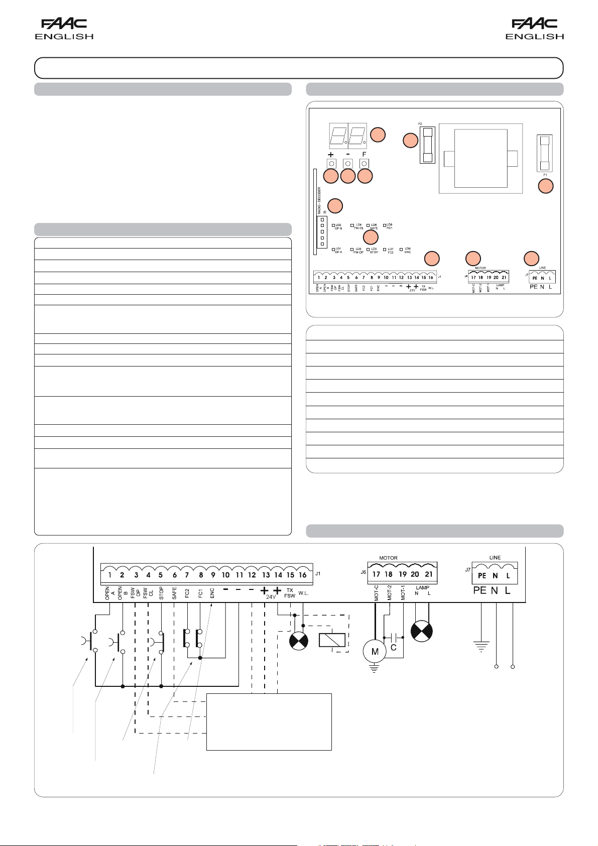
3. LAYOUT AND COMPONENTS
Important: Before attempting any work on the control board
(connections, maintenance), always turn off power.
- Install, upstream of the system, a differential thermal breaker with
adequate tripping threshold.
- Connect the earth cable to the appropriate terminal on the J7
connector of the equipment (see fig.2).
- Always separate power cables from control and safety cables
+
(push-button, receiver, photocells, etc.). To avoid any electric
noise, use separate sheaths or a shielded cable (with earthed
shield).
J2
2. TECHNICAL SPECIFICATIONS
Power supply V~ (+6% -10%) 230
Absorbed power (W) 10
Motor max. load (W) 1000
Accessories max. load (A) 0,5
Operating ambient temperature -20 °C +55 °C
Protection fuses 2 (see fig. 1)
Function logics: Automatic / “Stepped” automatic / Semi-automatic /
Safety devices / Semi-automatic B / Dead-man C / “Stepped” semiautomatic / Mixed B/C logic
Work time Programmable (from 0 to 4 min.)
Pause time Programmable (from 0 to 4 min.)
Thrust force Adjustable over 50 levels
Terminal board inputs: Open - Partial Open - Opening safety devices - Closing
safety devices - Stop - Edge - Power supply+Earth - Opening and closing limitswitches - Encoder
Terminal board outputs: Flashing lamp - Motor - 24 Vdc accessories power
supply- 24 Vdc indicator-light / Timed output / Electric lock command 'traffic lights' - Failsafe
Rapid connector 5-pin card connection for Minidec, Decoder or RP receivers
Programming 3 keys (+, -, F) and display, "basic" or "advanced" mode
Basic mode programmable functions: Function logic - Pause time - Thrust Force
- Opening-closing direction
Advanced mode programmable functions: Torque at initial thrust - Braking - Fail
safe- Pre-flashing - Indicator-light/Timed output/Electric lock or 'traffic lights'
command -Opening and closing safety devices logic - Encoder/ Anti-crushing
sensitivity -Decelerations - Partial opening time - Work time - Assistance request
- Cycle counter
DL SIGNALLING AND PROGRAMMING DISPLAY
Led INPUTS STATUS CONTROL LED
J1 LOW VOLTAGE TERMINAL BOARD
J2 CONNECTOR FOR DECODER/MINIDEC/RP RECEIVER
J6 MOTORS AND FLASHING LAMP CONNECTION TERMINAL BOARD
J7 230 Vac POWER SUPPLY TERMINAL BOARD
F1 MOTORS AND TRANSFORMER PRIMARY WINDING FUSE (F 5A)
F2 LOW VOLTAGE AND ACCESSORIES FUSE (T 800mA)
F "F" PROGRAMMING PUSH-BUTTON
– "–" PROGRAMMING PUSH-BUTTON
+ "+" PROGRAMMING PUSH-BUTTON
DL
F
–
Led
F2
J1
J6
F1
J7
Fig. 1
TOTAL
OPEN
PARTIAL
OPEN
STOP
LIMIT-SWITCH
ENCODER
24 Vdc
max 3 W
For connection of the
photocells and safety
devices, see paragraph
4.1.
4. ELECTRIC CONNECTIONS
230 Vac
(max. 60W)
230Vac
50-60Hz
NB.: The capacitor is supplied with the operator.
Fig. 2
15
Page 3
NOTE: The 578D equipment is able to command electro-
mechanical operators for sliding gates and industrial sectional
doors. Anything referring to gates in these instructions also
applies to doors. Any differences are shown in the specific
paragraphs.
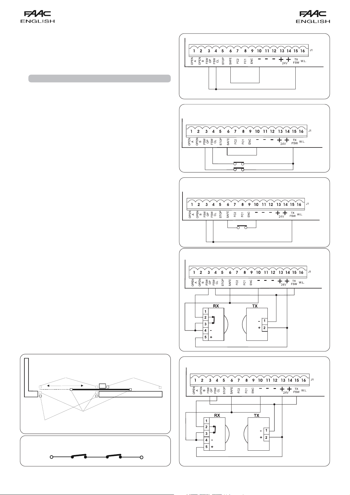
4.1. Connection of photocells and safety devices
Before connecting the safety devices and photocells we advise
you to select the type of operation according to the movement
area they have to protect (see fig.3 for example):
Opening safety devices:
detected only during gate opening movement. They
cause immediate closure and resumption of opening
motion on release (see programming in par.5.2).
Closing safety devices:
detected only during gate closing movement. They
cause re-opening, either immediate or on release (see
programming in par.5.2).
Opening/closing safety devices:
gate opening and closing movements. They cause
stopping and restart motion on release.
"Edge" safety devices:
and closing movements. They cause immediate reversal
of motion and stopping after two seconds.
Encoder:
it is tripped if there is an obstacle during gate opening
and closing movements. It causes immediate reversal of
motion and stopping after two seconds.
Note: in operators for industrial sectional doors, the anticrushing function is not tripped during closing, because
the operator acts on the rope shaft and not directly on
the door.
they are tripped when an obstacle is
they are tripped when an obstacle is
they are tripped during the
they are tripped during the gate opening
N.B. If two or more safety devices have the same function
(opening, closing, opening and closing, edge), the contacts
must be connected to each other in series (fig. 4).
N.C. contacts must be used.
N.B: If safety devices are not used, jumper connect the terminals
as shown in fig. 5.
The most common photocell and safety device lay-outs are
shown below (from fig. 6 to fig. 13).
Connection of no safety device
Fig. 5
Connection of a closing safety device and an opening
safety device
Fig. 6
Connection of an "edge" safety device
Fig. 7
Connection of a pair of opening photocells
Closing
photocells
Closing photocells
Connection of two N.C. contacts in series
(e.g. Photocells, Stop, Edge, etc.)
"Edge" safety
devices
Opening or
opening/closing
photocells
Fig. 3
Fig. 4
Fig. 8
Connection of a pair of closing photocells
Fig. 9
16
Page 4
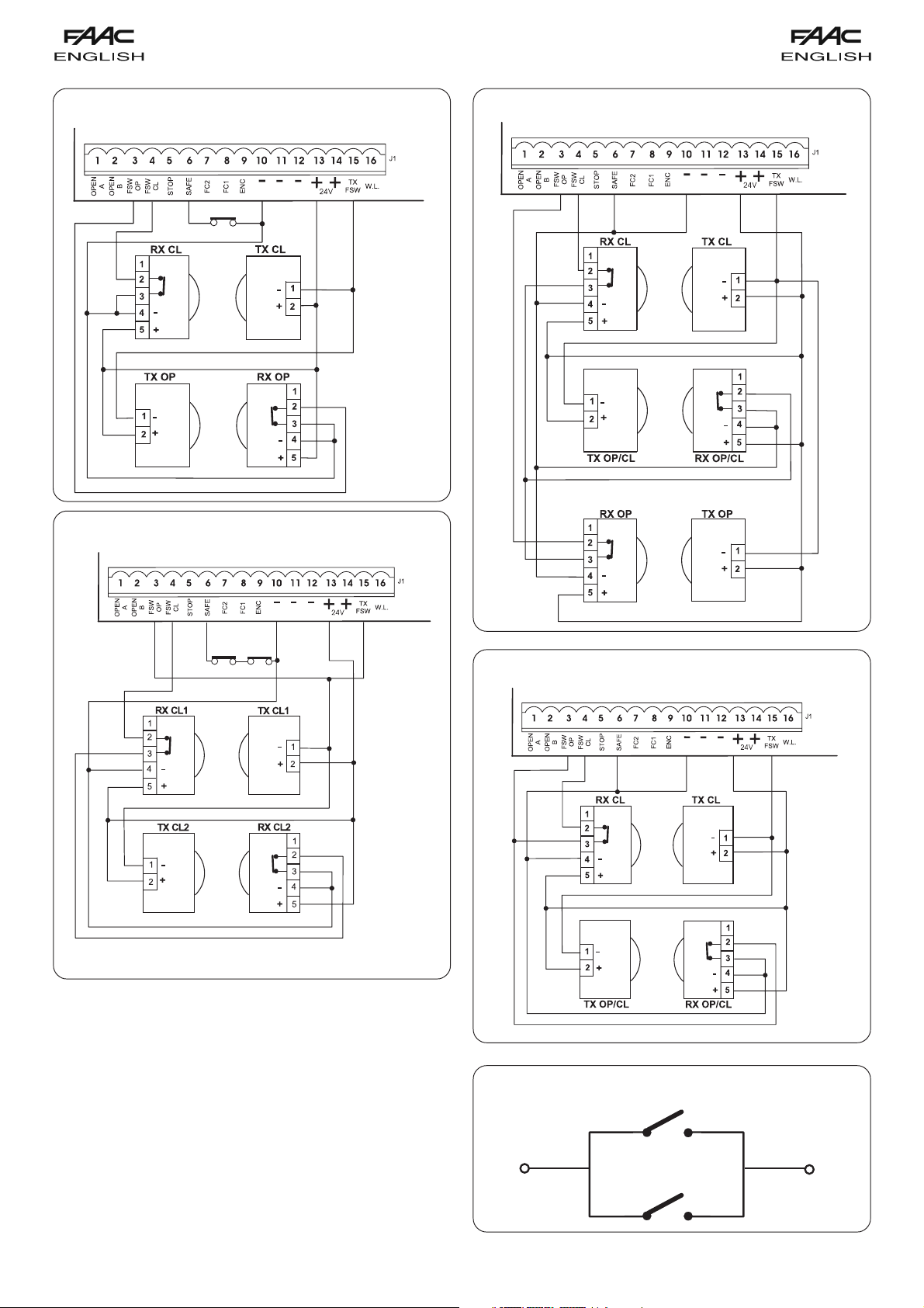
Connection of a pair of opening photocells, a pair of
closing photocell and an edge safety device
Fig. 10
Connection of a pair of closing photocells, a pair of
opening photocells and a pair of opening/closing
photocells
Connection of two pairs of closing photocells and two
edge safety devices
Fig. 11
Fig. 12
Connection of a pair of closing photocells and a pair of
opening/closing photocells
17
Fig. 13
Connection of two N.O. contacts in parallel
(e.g. Open A, Open B)
Fig. 14
Page 5

4.2. Terminal board - Power supply (fig. 2)
POWER SUPPLY (terminals PE-N-L):
PE: Earth connection
N:Power supply ( Neutral )
L:Power supply ( Line )
NB.: For correct operation, the board must be connected to the
earth conductor in the system. Install an adequate differential
thermal breaker upstream of the system.
4.3. J6 Terminal board - Motors and flashing lamp (fig. 2)
MOTOR - (terminals 17-18-19): Motor connection.
Operators for sliding gates: refer to paragraph 4.6 for
instructions on correct connection of the equipment to
the interface board on the operator.
Operator 541: refer to paragraph 4.7 for instructions on correct
connection of the equipment to the interface board on
the operator.
LAMP - (terminals 20-21): Flashing lamp output 230Vac
max 60W.
4.4. J1 Terminal board - Accessories (fig. 2)
Consult the relevant tables for a detailed description of
operation in the different logics
OPEN A - “Total Opening” command (terminal 1): any pulse
generator (push-button, detector, etc.) which, by
closing a contact, commands total opening and/or
closing of the gate leaf.
To install several total opening pulse generators,
connect the N.O. contacts in parallel (fig. 14).
OPEN B - “Partial opening” or “Closing” command (terminal 2):
FSW OP - Opening safety devices contact (terminal 3): The purpose
FSW CL - Closing safety devices contact (terminal 4): The purpose
any pulse generator (push-button, detector, etc.)
which, by closing a contact, commands partial
opening and/or closing of the gate leaf.
B/C logics, it always commands gate closure.
To install several partial opening pulse generators,
connect the N.O. contacts in parallel (fig.14).
of the opening safety devices is to protect the leaf
movement area during opening. During opening, in the
A-AP-S-E-EP logics the safety devices reverse the
movement of the gate, or stop and restart the movement
when it is released (see advanced programming in
Chpt. 5.2). During the opening cycle in logicsthe B, C and
B/C, they interrupt movement.
the closing cycle.
If the Opening safety devices are engaged when the
gate is closed, they prevent the opening movement.
To install several safety devices, connect the N.C. contacts
in series (fig.4).
They never operate during
In the B, C and
NB.: If no opening safety devices are connected, jumper
connect inputs FSW OP and -TX FSW (fig. 5).
of the closing safety devices is to protect the gate
movement area during closing. During closing, in the A-
AP-S-E-EP logics, the safety devices reverse the
movement of the gate, or stop and reverse the movement
when it is released (see advanced programming in
Chpt. 5.2). During the closing cycle in logics B, C and B/
C, they interrupt movement.
the opening cycle. If the Closing safety devices are
They never operate during
engaged when the gate is open, they prevent the
closing movement.
To install several safety devices, connect the N.C.
contacts in series (fig.4).
NB.: If no closing safety devices are connected, jumper
connect terminals FSW CL and -TX FSW
STOP - STOP contact (terminal 5): any device (e.g. a push-
button) which, by opening a contact, stops gate
movement.
To install several STOP devices, connect the N.C.
contacts in series (fig. 4).
(fig. 5).
NB.: If STOP devices are not connected, jumper connect
the STOP and - terminals.
SAFE - EDGE safety device contact (terminal 6): The purpose of
the "edge" safety device is to protect the leaf movement
area during opening/closing. In all logics, during opening
and closing, the safety device reverses gate movement
for 2 seconds. If the safety devices operate again during
the 2-seconds reversing time, it stops movement (STOP)
without any reversing.
If the Edge safety device is engaged while the gate is
closed or open, it prevents movement.
To install several safety devices, connect the N.C. contacts
in series (fig.4).
NB.: If edge safety devices are not connected, jumper
connect the SAFE and - inputs (fig. 5).
FC1 / FC2- Opening and closing limit-switch contacts (terminals
7 and 8): The purpose of the opening and closing limit-
switches is to establish the reference point for the stop,
or for start of deceleration (pre- and post-limitswitch),
or for operator braking (see advanced programming in
Chpt 5.2). The limit-switch device must have an NC
contact for connection between the input (FC1 or
FC2) and the equipment's terminal (see Fig.2).
OPERATORS FOR SLIDING GATES: consult paragraph 4.6
for correct connection of limit-switches and motor.
OPERATOR 541: consult paragraph 4.7 for correct
connection of limit-switches and motor.
ENCODER - Contacts of motor rotation control sensor (terminal 9):
This input is designed for connection of the Encoder
sensor. The presence of the encoder is signalled - when
the gearmotor is running - by the flashing of the "ENC"
LED on the board. If the encoder is used, the
equipment knows the exact gate position during the
entire movement, and also controls other functions
with greater precision, such as partial opening and
decelerations (see advanced programming in Chpt
5.2.). The encoder also operates as an anti-crushing
device: if the gate strikes an obstacle during opening
or closing, the encoder reverses gate leaf movement
for 2 seconds. If the encoder operates again during the
2-second reversing time, it STOPS movement without
performing any reversing.
Note: in operators for industrial
sectional doors, the anti-crushing function is not active
during closing, because the operator acts on the rope
shaft and not directly on the door.
–
+ 24 Vdc - Positive for power supply to accessories
TX -FSW - Negative for power supply to photocell transmitters
Negative for power supply to accessories (terminals 10,
11 and 12)
(terminals 13 and 14)
Important: Accessories max. load is 500 mA. To calculate
absorption values, refer to the instructions for individual
accessories.
(terminal 15)
If you use this terminal for connecting the negative for
supplying power to the photocell transmitters, you
may, if necessary, also use the FAIL SAFE function (see
advanced programming in Chpt. 5.2).
If this function is enabled, the equipment checks
18
Page 6

operation of the photocells before every opening or
closing cycle.
W.L. - Power supply to indicator light / timed exit / electric lock/
'traffic lights' (terminal 16)
Connect any 24 Vdc - 3 W max indicator light, timed
exit, command device for electric lock or 'traffic lights'
between this terminal and the +24V (see advanced
programming in Chap. 5.2). To avoid geopardising
correct operation of the system, do not exceed the
indicated power.
4.5.
Connector J2 - Rapid connection to Minidec, Decoder and RP
This is used for rapid connection of Minidec, Decoder and RP
receivers (see fig. 15, 16 and 17). Connect the accessory, with
the components side facing the inside of the board. Insert and
remove after cutting power.
4.6. Connection of operator 844
Make the connections between the 578D equipment and
the inter-connection board mounted on the operator,
observing the diagram in fig.18. Refer to paragraph 6.2 for
instructions on putting into operation.
4.7. Connection of operator 541
Make the connections between the 578D equipment and
the inter-connection board mounted on the operator,
observing the diagram in fig.19.
A stop push-button, if any, must be located in series with respect
to the connection between the STOP input of 578D and the
SAFETY of the 541 INTERFACE. Refer to paragraph 6.3 for
instructions on putting into operation.
PLUS
PLUS
MINIDEC
Fig. 15
DECODER
Fig. 16
4.8.
Connection of operators without on-board interface
To make connections between the 578D equipment and
operators without a on-board interface board, use the diagram
figure 20. Refer to paragraph 6.2 for putting into operation,
taking care over the limit-switch connections.
RP
Fig. 17
FC1FC2
J2
J3
J5
FC1-FC 2
J1
J6
FC1-FC 2
J4
19
Fig. 18
Page 7

Fig. 19
Fig. 20
FC2
FC1
FC1
FC2
1
2
Fig. 21
20
Page 8

5. PROGRAMMING
To program operation of the automated system, you have to
access the "
Programming is split into two parts:
PROGRAMMING
" mode.
BASIC
and
ADVANCED
.
5.1. BASIC PROGRAMMING
To access BASIC PROGRAMMING, press key F:
•if you press it (and hold it down), the display shows the name of
the first function.
•if you release the key, the display shows the value of the function
that can be modified with keys + and -.
•if you press F again (and hold it down), the display shows the
name of the next function, etc.
•when you reach the last function, press F to exit the program,
and the display resumes showing the gate status.
The following table shows the sequence of functions accessible in
BASIC PROGRAMMING:
5.2. ADVANCED PROGRAMMING
To access ADVANCED PROGRAMMING, press key F and, as you
hold it down, press key
•if you release key + , the display indicates the name of the first
function.
•if you release key F too, the display shows the value of the
function that can be modified with keys + and -.
•if you press key F (and hold it down), the display shows the name
of the next function, and if you release it, the value that can be
modified with keys + and - is shown.
•when you reach the last function, press F to exit the program,
and the display resumes showing the gate status.
The following table shows the sequence of functions accessible in
ADVANCED PROGRAMMING:
+:
BASIC PROGRAMMING
Display Function Default
FUNCTION LOGICS (see table of logics):
= Automatic
= "Stepped" automatic
= "Safety" Automatic
= Semi-automatic
= "Stepped" Semi-automatic
= Dead-man
= "B" Semi-automatic
= Mixed Log. (B opening / C closing)
PAUSE TIME:
This has effect only if the automatic logic was
selected. Adjustable from
one-second steps.
Subsequently, display changes to minutes
and tens of seconds (separated by a point)
and time is adjusted in 10-second steps, up
to the maximum value of
E.g. if the display shows , pause time is
2 min. and 50 sec.
FORCE:
Adjusts Motor thrust.
= minimum force
= maximum force
OPENING DIRECTION:
Indicates the gate opening movement and makes it
possible not to change the motor and limit-switches
connections on the terminal board.
= Standard opening movement
= Reverse opening movement
STATUS OF AUTOMATED SYSTEM:
Exit from programming, save data, and return
to gate status viewing.
= Closed
= Now opening
= At "STOP"
= Open
= Pause
= "FAIL SAFE" tripped
= Now closing
= Now reversing
= Photocells tripped
F
to sec. in
minutes.
ADVANCED PROGRAMMING
Display Function Default
MAXIMUM TORQUE AT INITIAL THRUST:
The motor operate at maximum torque
(ignoring the torque setting) at start of
movement. Useful for heavy leaves.
= Active
= Disabled
FINAL BRAKING:
When the gate engages the opening or
closing limit-switch, a braking stroke can be
selected to ensure the leaf is stopped
immediately. If decelerations are selected,
braking starts when they finish.
At value, braking is disabled.
Time can be adjusted from to in
0.01-second steps.
= Braking disabled
from
FAIL SAFE:
If this function is activated, it enables a
function test of the photocells before any
gate movement. If the test fails (photocells
not serviceable signalled by value on
the display), the gate does not start moving.
PRE-FLASHING (5 s):
Activates the flashing lamp for 5 seconds
before start of movement.
to = Timed braking
= Active
= Disabled
= Disabled
= Only before opening
= Only before closing
= Before every movement
F
+
+
21
Page 9

Display Function Default Display Function Default
INDICATOR-LIGHT:
If is selected, the output functions as
a standard indicator-light (lighted at
opening and pause, flashing at closing,
and off when gate closed).
Courtesy light: Different figures correspond
to timed activation of the output, which
can be used (by a relay) to power a courtesy
lamp. Time can be adjusted from to
sec. in 1-second steps, and from to
min. in 10-second steps.
Electric lock command and 'traffic lights'
functions:
If you press key - from the setting, the
command for the closing electric lock
is activated;
If you press - again, the command for the
closing and opening electric lock is set;
if you press the - key again, you can set the
'traffic lights' functions and .
= Standard indicator-light
from to = Timed output.
= electric lock command before
opening movement
= electric lock command before
opening and closing movements
= 'traffic lights' function: the output is
active in "open" and "open on pause"
status
and is disabled 3 seconds before the closing
manoeuvre starts.
Note: there is 3 seconds of pre-flashing
before the closing manoeuvre.
= 'traffic lights' function: the output is
active only in "closed" status.
Attention: do not exceed the output's maximum
load (24Vdc-3W). If necessary, use a relay and
a power supply source outside the equipment.
ENCODER:
If the encoder is used, you may select its
presence.
If the encoder is present and enabled,
"decelerations" and "partial opening" are
controlled by the encoder (see relevant
paragraphs).
The encoder operates as an anti-crushing
device: If the gate strikes an obstacle during
opening or closing, the encoder
immediately reverses gate leaf movement
for 2 seconds. If the encoder operates
again during the 2-seconds reversing time,
it stops movement (STOP) without
commanding any reversing. If no sensor is
supplied, the parameter must be set on
. If there is the encoder, adjust the
sensitivity of the anti-crushing system, by
varying the parameter between
(maximum sensitivity) and (minimum
sensitivity).
from to = Encoder active and
sensitivity adjustment
= Encoder disabled
Pre-limit switch DECELERATION:
You can select gate deceleration before
the opening and closing limit-switches have
been tripped.
Time can be adjusted from to in
0.04-second steps.
If an encoder is used, the adjustment is not
determined by time but by motor revs, thus
obtaining greater deceleration precision.
= Deceleration disabled
from to = Deceleration enabled
CLOSING PHOTOCELLS LOGIC:
Select the tripping mode of the closing
photocells.
They operate for the closing movement
only: they stop movement and reverse it
when they are released, or they reverse it
immediately.
= Reverse on release
= Reverse immediately to opening
OPENING PHOTOCELLS LOGIC:
Select the tripping mode of the opening
photocells.
They operate for the opening movement
only: they stop the movement and restart
it when they are released, or they reverse it
immediately.
= Reverse immediately to closing
= Restart movement on release
Post-limit switch DECELERATION:
You can select gate deceleration after the
opening and closing limit-switches have
been tripped.
Time can be adjusted from to in
0.02-second steps.
If an encoder is used, the adjustment is not
determined by time but by motor revs, thus
obtaining greater deceleration precision.
= Deceleration disabled
from to = Deceleration enabled
PARTIAL OPENING:
You can adjust the width of partial leaf
opening.
Time can be adjusted from to in
1-second steps.
If an encoder is used, the adjustment is not
determined by time but by motor revs, thus
obtaining greater partial-opening
precision. For example, with pinion Z20,
partial opening can vary from about 60 cm
to 4 m.
22
Page 10

Display Function Default
WORK TIME (time-out):
We advise you to set a value of 5 to 10
seconds over the time taken by the gate to
travel from the closing limit-switch to the
opening limit-switch and vice versa.
Adjustable from to sec. in onesecond steps.
Subsequently, display changes to minutes
and tens of seconds (separated by a point)
and time is adjusted in 10 second steps, up
to a maximum value of minutes.
Attention: the set value does not exactly
matchthe motor's maximum operating time,
because the latter is modified according to
the performed deceleration spaces.
ASSISTANCE REQUEST (combined with next
function):
If activated, at the end of countdown
(settable with the next function i.e. "Cycle
programming") it effects 2 sec. (in addition
to the value already set with the PF function)
of pre-flashing at every Open pulse (job
request). Can be useful for setting
scheduled maintenance jobs.
= Active
= Disabled
6. START-UP
6.1. Inputs check
The table below shows the status of the LEDs in relation to to the
status of the inputs.
Note the following:
LED
LIGHTED
= closed contact
LED
OFF
= open contact
Check the status of the LEDs as per Table.
Operation of the signalling status LEDs
LEDS LIGHTED OFF
OP-A Command activated Command inactive
OP-B Command activated Command inactive
FC1 Limit-switch free Limit-switch engaged
FC2 Limit-switch free Limit-switch engaged
FW OP
FW CL
STOP Command inactive Command activated
SAFE
ENC Flashes while the motor rotates
Safety devices disengaged Safety devices engaged
Safety devices disengaged Safety devices engaged
Safety devices disengaged Safety devices engaged
NB.:
•The status of the LEDs while the gate is closed at rest are shown
in bold.
•If the Encoder sensor is not installed, the ENC LED is always OFF.
•If you select the reverse opening direction (see par.5.1), the
operation of the limit-switches is also reversed. Therefore, in
closed status, the engaged limit-switch will be FC1 (LED OFF).
CYCLE PROGRAMMING:
For setting countdown of system operation
cycles. Settable (in thousands) from
to thousand cycles.
The displayed value is updated as cycles
proceed.
This function can be used to check use of
the board or to exploit the "Assistance
request".
GATE STATUS:
Exit from programming, data saving, and return
to viewing gate status (see par. 5.1.).
NB.: modification of programming parameters comes into effect
immediately, whereas definitive memory storage occurs only
when you exit programming and return to gate status viewing. If
the equipment is powered down before return to status viewing,
all modifications will be lost.
To restore the default settings of the programming disconnect
terminal strip J1, press the three buttons +, -, F simultaneously and
keep them pressed for 5 seconds.
6.2. Installation using sliding gate operators
When you have made the connections between the 578D
equipment and the on-board operator interface board, and
have fitted the travel-limit plates on the rack (see operator
instructions), check opening direction and limit-switch efficiency,
as follows:
•Power up the system.
•Select the opening direction (see par.5.1.). If you look at the
gate from the side where the operator is installed, the opening
movement should be from left to right - if it is, select the
standard direction, otherwise select the reverse direction.
•Set parameter EC on 00 (see parl.5.2).
•When you made the modifications, exit programming, return
to inputs viewing and then power down and power up the
system.
•Release the operator and, sliding the gate manually, check
the efficiency of the limit-switches, controlling the status LEDs
of the inputs (see par.6.1). If you look at the gate from the side
where the operator is installed, the FC1 LED should go off when
the stop position of the left to right movement is reached, and
FC2 should go off when the stop position of the right to left
movement is reached (also see fig.21).
•Lock the operator about midway along its travel.
•Give an OPEN A command and check if the gate moves in
opening direction. If it does not, lock the movement and,
after cutting the power to the system, change over the wires
connected to terminals of MOT-1 and MOT-2.
23
Page 11

NOTE-For motors with an inductive sensor (746 and 844) take
care over setting post-limitswitch deceleration and braking: if
deceleration is too long or braking is insufficient, the plate fitted
on the gate rack can go beyond the sensor until it disengages
the sensor. When the gate is stopped, check if only the limitswitch involved is engaged. The relevant LED must be off. If it
went off and then re-lighted, or if both the LEDs of the limitswitches are off, reduce the post-limitswitch deceleration value
and/or increase braking value.
6.3. Installation using the 541 operator
When you have made the connections between the 578D
equipment and the on-board operator interface board, and
have adjusted the limit-switches (see operator instructions),
check opening direction as follows:
•Cut power to the system.
•Release the operator and partially open the door.
•Lock the operator, power up the system again and command
opening. If the door begins its closing movement, change
opening direction (see Par.5.1). After you have changed it,
return to viewing automated system status, and then power
down and power up the equipment.
NOTE-
For perfect installation of the 578D equipment, using
sectional doors operator 541, take care over the following
aspects:
OPENING DECELERATION:
during deceleration also reduces the force it can deliver. If the
door is not well balanced, 541 may not be able to perform
deceleration at end of opening (door with strong tendency to
close) or closing (door with strong tendency to open), because
the delivered force is not sufficient to overcome the imbalance.
In this case, 0 must be set as the pre- and post-limitswitch
deceleration value (see advanced programming in Par.5.2),
because a different value could prevent the limit-switch being
reached or prevent reversal of motion following tripping of the
anti-crushing system.
ANTI-CRUSHING SAFETY DEVICE DURING CLOSING:
has an Encoder sensor, the 541 operator cannot intrinsically
guarantee this safety device, because it is not fitted directly on
the door, but acts on the rope winding shaft. Therefore, the
ENCODER sensor cannot detect any obstacle during closing.
In this connection, we recommend to observe current legal
regulations for protecting the lower part of the door.
the reduction of the operator's speed
although it
7. FINAL OPERATIONS
At end of programming, run a few complete cycles to check if the
automated system and the accessories connected to it are
operating correctly, giving special attention to safety devices,
operator thrust force adjustment, and to the anti-crushing device
(Encoder sensor). Hand over the "User's guide" page (in the
operator instructions) to the customer, and describe how the
system works, as well as the operator release and locking operations
indicated in the said guide.
24
Page 12

)2("2rofnepootsesreveR
)2("2rofnepootsesreveR
)1(emitesuapsdaoleR
)2("2rofesolcotsesreveR
)delbasidNEPO(
)2("2rofnepootsesreveR
)2("2rofesolcotsesreveR
emitesuapsdaoleR
)delbasidNEPO(
)1(emitesuapsdaoleR
)2("2rofesolcotsesreveR
)delbasidNEPO(
)2("2rofnepootsesreveR
)2("2rofesolcotsesreveR
)delbasidNEPO(
tceffeoN
otsesrever,esaelerno,dnaskcoL
)1(emitesuapsdaoleR
)delbasidNEPO(
nepo
)3()1(emitesuapsdaoleR
.2.5hpargarapees
tceffeoN
)delbasidANEPO.gnpo.trapnofi(
)NEPOsevas(
tceffeoN
tceffeoN
)delbasidNEPO(
tceffeoN
seunitnoc,esaelerno,dnaskcoL
gninepo
tceffeoN
)delbasidNEPO(
tceffeoN
otsesrever,esaelerno,dnaskcoL
emitesuapsdaoleR
)delbasidNEPO(
nepo
)3(emitesuapsdaoleR
.2.5hpargarapees
)delbasidNEPO(
tceffeoN
)delbasidANEPO.gnpo.trapnofi(
)NEPOsevas(
tceffeoN
tceffeoN
)delbasidNEPO(
tceffeoN
seunitnoc,esaelerno,dnaskcoL
gninepo
tceffeoN
)delbasidNEPO(
tceffeoN
otsesrever,esaelerno,dnaskcoL
"5retfasesolc,esaelernO
)delbasidNEPO(
nepo
NEPO("5retfasesolc,esaelernO
.2.5hpargarapees
)3()delbasid
tceffeoN
)delbasidANEPO.gnpo.trapnofi(
)NEPOsevas(
tceffeoN
tceffeoN
)delbasidNEPO
tceffeoN
seunitnoc,esaelerno,dnaskcoL
gninepo
)NEPOsevas(
tceffeoN
tceffeoN
)delbasidNEPO(
)delbasidNEPO(
tceffeoN
tceffeoN
otsesrever,esaelerno,dnaskcoL
nepo
.2.5hpargarapees
)delbasidNEPO(
)3(tceffeoN
tceffeoN
)delbasidANEPO.gnpo.trapnofi(
)NEPOsevas(
tceffeoN
tceffeoN
)delbasidNEPO(
tceffeoN
seunitnoc,esaelerno,dnaskcoL
gninepo
tceffeoN
)delbasidNEPO(
tceffeoN
)delbasidNEPO(
tceffeoN
noitarepo
spotS
retfasesolcdnaemitgninepo
laitrapehtroffaelsnepO
)1(emitesuap
)1(yletaidemmifaelehtsnepo-eR
)3()1(emitesuapsdaoleR
)3(faelehtsesolC
)3()1(tceffeoN .2.5hpargarapeestceffeoN
sesolcdnafaelehtsnepO
)1(emitesuapretfati
)delbasidNEPO(
tceffeoN
)delbasidNEPO(
tceffeoN
noitarepo
spotS
retfasesolcdnaemitgninepo
laitrapehtroffaelsnepO
emitesuap
)3(noitarepospotS
sesolcdnafaelehtsnepO
emitesuapretfati
,degagnesecivedytefaSgnisolChtiw(faelehtsesolC
yletaidemmifaelehtsnepo-eR
)3()eslupdn2ehttasnepo
)3(noitarepospotS .2.5hpargarapeestceffeoN
)delbasidNEPO(
tceffeoN
)delbasidNEPO(
tceffeoN
noitarepo
spotS
retfasesolcdnaemitgninepo
laitrapehtroffaelsnepO
emitesuap
)3(yletaidemmifaelehtsesolc-eR
sesolcdnafaelehtsnepO
emitesuapretfati
)3(yletaidemmifaelehtsesolc-eR .2.5hpargarapees
yletaidemmifaelehtsnepo-eR
)3(faelehtsesolC
)delbasidNEPO(
tceffeoN
)delbasidNEPO(
tceffeoN
noitarepo
spotS
laitrapehtroffaelsnepO
emitgninepo
)3(yletaidemmifaelehtsesolc-eR
faelehtsnepO
,degagnesecivedytefaSgnisolChtiw(faelehtsesolC
yletaidemmifaelehtsnepo-eR
)3()eslupdn2ehttasnepo
)3(noitarepospotS .2.5hpargarapeestceffeoN
SUTATSETAGA-NEPOB-NEPOPOTSSECIVEDYTEFASGNINEPOSECIVEDYTEFASGNISOLCECIVEDYTEFASLC/POECIVEDYTEFASEGDE
"A"cigoL SESLUP
Tab. 3/a
ESUAPnoNEPO
GNINEPO
DESOLC
GNISOLC
DEKCOL
SUTATSETAGA-NEPOB-NEPOPOTSSECIVEDYTEFASGNINEPOSECIVEDYTEFASGNISOLCECIVEDYTEFASLC/POECIVEDYTEFASEGDE
"PA"cigoL SESLUP
Tab. 3/b
ESUAPnoNEPO
GNINEPO
DESOLC
GNISOLC
DEKCOL
SUTATSETAGA-NEPOB-NEPOPOTSSECIVEDYTEFASGNINEPOSECIVEDYTEFASGNISOLCECIVEDYTEFASLC/POECIVEDYTEFASEGDE
"S"cigoL SESLUP
Tab. 3/c
ESUAPnoNEPO
GNINEPO
DESOLC
GNISOLC
DEKCOL
SUTATSETAGA-NEPOB-NEPOPOTSSECIVEDYTEFASGNINEPOSECIVEDYTEFASGNISOLCECIVEDYTEFASLC/POECIVEDYTEFASEGDE
"E"cigoL SESLUP
DESOLC
NEPO
GNINEPO
GNISOLC
DEKCOL
Tab. 3/d
25
Page 13

)2("2rofnepootsesreveR
)2("2rofesolcotsesreveR
)2("2rofnepootsesreveR
)delbasidB/A-NEPO(
)2("2rofnepootsesreveR
)delbasidB/A-NEPO(
)2("2rofnepootsesreveR
)delbasidB/A-NEPO(
tceffeoN
)delbasidNEPO(tceffeoN
)delbasidANEPO(
tceffeoN
seunitnoc,esaelerno,dnaskcoL
otsesrever,esaelerno,dnaskcoL
)delbasidB/A-NEPO(
)delbasidBNEPO(
noitarepospotS
gninepo
nepo
)3()delbasidNEPO(tceffeoN )delbasidNEPO(tceffeoN
tceffeoN )delbasidNEPO(tceffeoN
)NEPOselbasidti,esolctsumtifi(
tceffeoN
tceffeoN
)delbasidBNEPO(
)delbasidB-NEPO(
noitarepospotS
tceffeoN
tceffeoN
tceffeoN )2("2rofesolcotsesreveR
tceffeoN
)delbasidANEPO(
tceffeoN
)delbasidBNEPO(
tceffeoN
)delbasidB-NEPO(
)delbasidBNEPO(
noitarepospotS
tceffeoN
tceffeoN
)delbasidB/ANEPO(
tceffeoN
)delbasidB/A-NEPO(
noitarepospotS
)delbasidBNEPO(
tceffeoN
tceffeoN )2("2rofesolcotsesreveR
tceffeoN
)delbasidANEPO(
tceffeoN
)delbasidBNEPO(
noitarepospotS
tceffeoN
)delbasidB-NEPO(
)delbasidBNEPO(
noitarepospotS
tceffeoN
tceffeoN
)delbasidB/ANEPO(
tceffeoN
)delbasidB/A-NEPO(
)delbasidBNEPO(
tceffeoN
tceffeoN )2("2rofesolcotsesreveR
ANEPO.gnpo.trapnofi(tceffeoN
)delbasid
)delbasidNEPO(
tceffeoN
noitarepo
spotS
laitrapehtroffaelsnepO
emitgninepo
)3(yletaidemmifaelehtsesolc-eR
noitarepospotS )NEPOsevas(tceffeoN.2.5hpargarapees
)NEPOselbasidti,nepotsumtifi(
)delbasidA-NEPO(
)delbasidANEPO(
tceffeoN
)delbasidNEPO(
tceffeoN
)3(noitceridesrevernitnemevomstratseR
)potSaretfasesolcsyawla(
)3(noitarepospotS .2.5hpargarapeestceffeoN
tceffeoN
)delbasidANEPO(
tceffeoN
)delbasidB/A-NEPO(
tceffeoN
)delbasidA-NEPO(
faelehtsesolC
tceffeoN
)delbasidA-NEPO(
noitarepospotS
tceffeoN
noitarepospotS
tceffeoN
)delbasidANEPO(
tceffeoN
NEPO(tceffeoN
)delbasidB
)delbasidA-NEPO(
)ANEPOsevas(
noitarepospotS
tceffeoN
tceffeoN
)delbasidANEPO(
tceffeoN
)delbasidB/ANEPO(
tceffeoN
noitarepo
spotS
)ANEPOsevas(
tceffeoN
tceffeoN
)delbasidBNEPO(
tceffeoN
spotS
)delbasidA-NEPO(
)delbasidA-NEPO(
noitarepospotS
tceffeoN
NEPO(tceffeoN
)delbasidB/A
noitarepo
SUTATSETAGA-NEPOB-NEPOPOTSSECIVEDYTEFASGNINEPOSECIVEDYTEFASGNISOLCECIVEDYTEFASLC/POECIVEDYTEFASEGDE
"PE"cigoL SESLUP
Tab. 3/e
)delbasidB-NEPO(
faelehtsnepO
GNINEPO
DESOLC
GNISOLC
NEPO
DEKCOL
Tab. 3/f
faelehtsnepO
SUTATSETAG)gninepo(A-NEPO)gnisolc(B-NEPOPOTSSECIVEDYTEFASGNINEPOSECIVEDYTEFASGNISOLCECIVEDYTEFASLC/POECIVEDYTEFASEGDE
"C"cigoLNWODDLEHSYAWLASLORTNOC SESLUP
DESOLC
noitarepospotS/
tceffeoN
/noitarepospotS
GNINEPO
GNISOLC
NEPO
Tab. 3/g
faelehtsnepOtceffeoN
SUTATSETAG)gninepo(A-NEPO)gnisolc(B-NEPOPOTSSECIVEDYTEFASGNINEPOSECIVEDYTEFASGNISOLCECIVEDYTEFASLC/POECIVEDYTEFASEGDE
"B"cigoL SESLUP
DESOLC
nepootsesreveRtceffeoN
tceffeoNfaelehtsesolC
GNISOLC
NEPO
faelehtsnepOfaelehtsesolC
tceffeoNtceffeoN
GNINEPO
DEKCOL
faelehtsnepOtceffeoN
"C/B"cigoLSLORTNOCNUROTDLOHGNISOLC/ESLUPGNINEPO SESLUP
SUTATSETAG)gninepo(A-NEPO)gnisolc(B-NEPOPOTSSECIVEDYTEFASGNINEPOSECIVEDYTEFASGNISOLCECIVEDYTEFASLC/POECIVEDYTEFASEGDE
DESOLC
Tab. 3/h
nepootsesreveRtceffeoN
tceffeoNfaelehtsesolC
GNISOLC
NEPO
faelehtsnepOfaelehtsesolC
tceffeoNtceffeoN
GNINEPO
DEKCOL
(1) If maintained, it prolongs the pause until disabled by the command (timer function) (3) During the partial opening cycle, an OPEN A pulse causes total opening.
(2) If a new pulse occurs within 2 seconds after reversing, it immediately stops operation. NB.: Effects on other active pulse inputs in brackets.
26
 Loading...