

Page 1
ENGLISH
CE DECLARATION OF CONFORMITY
Manufacturer: FAAC S.p.A.
Address: Via Benini, 1 - 40069 Zola Predosa BOLOGNA - ITALY
Declares that: 462 DF control board,
• conforms to the essential safety requirements of the following directives:
73/23/EEC and subsequent amendment 93/68/EEC.
89/336/EEC and subsequent amendment 92/31/EEC and 93/68/EEC
Additional note:
This product underwent tests in a typical uniform configuration
(all products manufactured by FAAC S.p.A.).
Bologna, 01 January 2002
The Managing Director
A. Bassi
ENGLISH
WARNINGS FOR THE INSTALLER
GENERAL SAFETY OBLIGATIONS
1 ) CAUTION! It is important for personal safety to follow all the instructions
carefully. Incorrect installation or misuse of the product may cause
people serious harm.
2) Read the instructions carefully before starting to install the product.
3) Packaging material (plastic, polystyrene, etc.) must not be left within reach
of children as it is a potential source of danger.
4) Keep the instructions for future reference.
5) This product was designed and manufactured strictly for the use indicated
in this documentation. Any other not expressly indicated use may damage
the product and/or be a source of danger.
6) FAAC accepts no responsibility due to improper use of the automated
system or use other than that intended.
7) Do not install the equipment in an area subject to explosion hazard:
inflammable gases or fumes are a serious safety hazard.
8) Mechanical construction elements must meet the provisions of UNI8612,
EN 12604 and EN 12605 Standards.
To obtain an adequate level of safety in non EU countries, the above
mentioned Standards must be observed in addition to national Standards.
9) FAAC will not accept responsibility if the principles of Good Workmanship
are disregarded in constructing the closing elements to be motorised, and
if any deformation occurs during use of the said elements.
10) Installation must meet the following Standards: UNI8612, EN 12453 and EN
12445.
11) Before carrying out any work on the system, switch off the power supply.
12) The mains power supply of the automated system must be fitted with a allpole switch with contact opening distance of 3mm or greater. Use of a 6A
thermal breaker with all-pole circuit break is recommended.
13) Make sure there is a differential switch with 0.03A threshold upstream of the
system.
14) Check that the earthing system is correctly made and connect the closure
metal parts to it. Also connect the Yellow/Green wire of the automated
system to the earthing system.
15) The automated system includes an intrinsic anti-crushing device consisting
of a torque control which, however, must be installed together with other
safety devices.
16 ) The safety devices (EN 12978 Standard) protect any dangerous areas
against Mechanical movement risks, such as crushing, dragging, and
shearing.
17 ) Use of at least one indicator-light (e.g. FAAC LAMP MINILAMP, etc.) is
recommended for every system, as well as a warning sign adequately
fixed to the frame structure, in addition to the devices mentioned at point
“16”.
18) FAAC accepts no responsibility regarding safety and correct operation
of the automated system, should components made by manufacturers
other than FAAC be used in the system.
19) Use only FAAC original spare parts for maintenance.
20) Do not make any alterations to the components of the automated system.
21 ) The installer shall supply full information regarding manual operation of
the system in case of an emergency, and shall hand over to the user of the
system the warning handbook supplied with the product.
22) Do not allow children or other persons to stand near the product while in
operation.
23) Keep remote controls or any other pulse generator well away from
children, to prevent the automated system from being activated
accidentally.
24) The user must refrain from attempting to repair or adjust the system
personally and should contact qualified personnel only.
25 ) Anything not expressly provided for in these instructions is not permitted.
6
Page 2
ENGLISH
ENGLISH
CONTROL BOARD 462 DF
1. WARNINGS
Important: Before attempting any work on the control board
(connections, maintenance), always turn off power.
- Install, upstream of the system, a differential thermal breaker
with adequate tripping threshold.
- Connect the earth cable to the appropriate terminal on the J1
connector of the equipment (see fig.2).
- Always separate power cables from control and safety cables
(push-button, receiver, photocells, etc.). To avoid any electric
noise, use separate sheaths or a shielded cable (with earthed
shield).
2. TECHNICAL SPECIFICATIONS
Power supply 230 V~ ( +6% -10%) - 50 Hz
Absorbed power 35 W
Motor max. load 800 W
Power supply for accessories 24Vdc
Accessories max. load 0.5 A
Power supply for indicator-light 24Vdc max 3W
Electric lock max. load 15 VA
Operating ambient temperature -20 °C +55 °C
Protection fuses 2 (see fig. 1)
Rapid connector To connect Minidec, Decoder or RP cards
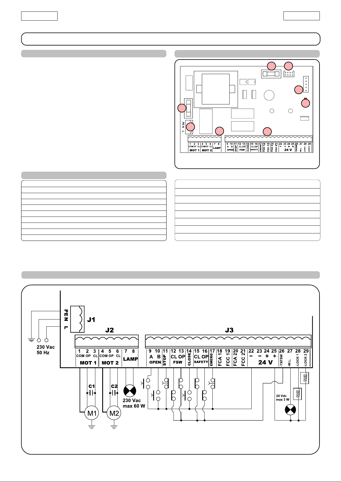
3. LAYOUT AND COMPONENTS OF 462 DF
F2
J5
J4
F1
J1
J2
J3
Led
Fig. 1
Led 'POWER ON' LED
J1 230 VAC POWER SUPPLY TERMINAL BOARD
J2 MOTORS AND FLASHING LAMP CONNECTION TERMINAL BOARD
J3 LOW VOLTAGE TERMINAL BOARD
J4 CONNECTOR FOR MINIDEC/DECODER/RP RECEIVER
J5 CONNECTOR FOR DIGIPROGRAM/FAACTOTUM
F1 MOTORS AND TRANSFORMER PRIMARY WINDING FUSE (F 5A)
F2 LOW VOLTAGE AND ACCESSORIES FUSE (T 800mA)
4. ELECTRIC CONNECTIONS
BLUE
BLUE
NB.: Capacitors are supplied with the operators.
Fig. 2
7
Page 3

ENGLISH
ENGLISH
4.1. Connection of photocells and safety devices
Before connecting the photocells (or other devices) we advise
you to select the type of operation according to the movement
area they have to protect (see fig.3):
Opening safety devices:
they operate only during the gate
opening movement and, therefore, they are suitable for
protecting the area between the opening leaves and
fixed obstacles (walls, etc) against the risk of impact
and crushing.
Closing safety devices:
they operate only during the gate closing
movement and, therefore, they are suitable for
protecting the closing area against the risk of impact.
Opening/closing safety devices:
they operate during the gate
opening and closing movements and, therefore, they
are suitable for the opening and closing areas against
the risk of impact.
FAAC recommends use of the lay-out in fig. 4 (in the event of fixed
obstacles at opening) or in fig. 5 (no fixed obstacles).
N.B. If two or more devices have the same function, they should
be connected to each other in series. N.C. contacts must be used.
Opening/closing safety devices
Connection of a pair of closing photocells (CL), a pair of
opening photocells (OP), and a pair of opening/closing
photocells (OP/CL)
Closing safety devices
Fig. 3
Opening
safety devices
Table: operation of safety inputs in logic A (standard)
LOGIC “A”
GATE STATUS FSW-OP FSW-CL FSW-OP/CL SAFETY-OP SAFETY-CL SAFETY-OP/CL
CLOSED
OPENING
OPEN ON PAUSE
CLOSING
PULSES
no effecf
(OPEN disabeld)
blocks and, on release,
reverses to close
no effect
-opening disabled-
no effect reverses to open
no effect no effecf
no effect blocks and, on release,
recounts pause time recounts pause time
(OPEN disabeld)
continues opening
blocks and, on release,
reverses to open no effect reverses to open
no effecf
(OPEN disabeld)
reverses to close no effect
no effect
-opening disabled-
no effect no effecf
no effect
-closing disabled-
(OPEN disabeld)
blocks movement
no effect
(OPEN/CLOSE
disabledi)
blocks movement
Fig. 4
STOPPED
no effect
-opening disabled-
no effect
-closing disabled-
➲ Effects on other active pulse inputs in brackets.
no effect
(OPEN/CLOSE
disabledi)
8
no effect
-opening disabled-
no effect
-closing disabled-
no effect
(OPEN/CLOSE
disabledi)
Page 4

ENGLISH
ENGLISH
Connection of a pair of closing photocells (CL) and a pair of
opening/closing photocells (OP/CL)
Fig. 5
Connection of two pairs of closing photocells (CL)
Fig. 8
Connection of one pair of closing photocells (CL)
Connection of one pair of opening photocells (OP)
Fig. 6
Fig. 7
Note : The connection examples refer to the "FSW" inputs;
connections to the "SAFETY" inputs can be obtained with
terminals 15 and 16 (instead of terminals 12 and 13).
4.2. Terminal board J1 - Power supply (fig. 2)
PE: Earth connection
N:230 V~ power supply ( Neutral )
L:230 V~ power supply ( Line )
NB.: For correct operation, the board must be connected to the
earth conductor in the system. Install an adequate differential
thermal breaker upstream of the system.
4.3. Terminal board J2 - Motors and flashing lamp (fig. 2)
M1 : COM / OP / CL: Connection to Motor 1
Can be used in the single-leaf application
M2 : COM / OP / CL: Connection to Motor 2
Cannot be used in the single-leaf application
LAMP : Flashing lamp output ( max 60 W 230 V ~)
4.4. Terminal board J3 - Accessories (fig. 2)
For exact operation of inputs according to gate status,
refer to the logic table being used (Digiprogram
instructions).
OPEN A “Total Opening” command (N.O.):
Any pulse generator (push-button, detector, etc.) which,
by closing a contact, commands opening and/or closing
of both gate leaves.
To install several total opening pulse generators, connect
the N.O. contacts in parallel.
OPEN B “Partial Opening” command (N.O.):
Any pulse generator (push-button, detector, etc.) which,
by closing a contact, commands opening and/or closing
of the leaf driven by motor M1.
To install several partial opening pulse generators, connect
the N.O. contacts in parallel.
9
Page 5

ENGLISH
ENGLISH
STOP STOP contact (N.C.):
Any device (e.g.: push-button) which, by opening a
contact, stops gate movement.
To install several STOP devices, connect the N.C. contacts
in series.
NB.: If STOP devices are not connected, jumper connect
the STOP and – terminals.
CL FSW Closing safety devices contact (N.C.):
Input for connection of safety devices (e.g. photocell)
which, when activated during closing, cause a reverse of
the movement to complete opening.
They never operate during the opening cycle.
If the closing safety devices operate when the gate is open,
they prevent the leaf closing movement.
NB.: If no closing safety devices are connected, jumper
connect terminals CL FSW and -TX FSW .
OP FSW Opening safety devices contact (N.C.):
Input for connection of safety devices (e.g. edge) which,
when activated during opening, cause a reverse of the
movement to complete closing.
They never operate during the closing cycle.
If the opening safety devices operate when the gate is closed,
they prevent the leaf opening movement.
NB.: If no opening safety devices are connected, jumper
connect inputs OP FSW and -TX FSW .
CLOSE "Closing" command (N.O.):
Any pulse generator (push-button, detector, etc.) which,
by closing a contact, commands gate closing only.
To install several full opening pulse generators, connect the
N.O. contacts in parallel.
CL SAFETY Closing edge contact (N.C.):
Input for connection of safety devices (e.g. edge) which,
when activated during closing, causes a reverse of the
movement to complete opening. If the OP Safety input is
activated within one second after tripping of the safety
device, the movement stops.
They never operate during the opening cycle.
If these closing safety devices operate when the gate is
open, they prevent the leaf closing movement.
NB.: If no closing safety devices are connected, jumper
connect terminals CL SAFETY and -TX FSW.
OP SAFETY Opening safety devices contact (N.C.):
Input for connection of safety devices (e.g. edge) which,
when activated during opening, cause a reverse of the
movement to complete closing. If the CL Safety input is
activated within one second after tripping of the safety
device, the movement stops.
They never operate during the closing cycle.
If these closing safety devices operate when the gate is
closed, they prevent the leaf opening movement.
NB.: If no opening safety devices are connected, jumper
connect terminals OP SAFETY and -TX FSW .
EMERG “Emergency Opening” command (N.C.):
Any pulse generator (push-button, etc.) which, by opening
a contact, commands an emergency opening irrespective
of the status of any other input.
To install several emergency opening pulse generators,
connect the N.C. contacts in series.
NB.: If emergency devices are not connected, jumper
connect the EMERG and – terminals.
FCA1/FCC1/FCA2/FCC2
Inputs for connection of Gatecoder or limit-switches: refer
to the Digiprogram or Faactotum instructions.
+ 24 Vdc - Positive for power supply to accessories
Important: Accessories max. load is 500 mA. To calculate
absorption values, refer to the instructions for individual
accessories.
-TX FSW Negative for power supply to photocell transmitters
If you use this terminal for connecting the negative for
supplying power to the photocell transmitters, you may, if
necessary, also enable the FAILSAFE function (enable it with
the Digiprogram or Faactotum).
If this function is enabled, the equipment checks operation
of the photocells before every opening or closing cycle.
W.L. Indicator-light
Connect a 24 Vdc - 3 W max. indicator-light, if necessary,
between this terminal and the +24V supply. To avoid
jeopardizing correct operation of the system,
the indicated power.
Operation of the indicator-light:
STATUS CLOSED OPENING OPEN/PAUSE CLOSING STOPPED
LIGHT Off Lighted Lighted Flashing Lighted
LOCK1 Leaf 1 electric lock
Connect a possible 12 Vac electric lock (releases on
opening) between this terminal and the +24V.
LOCK2 Leaf 2 electric lock
Connect a possible 12 Vac electric lock between this
terminal and the +24V.
NB.: Activation of the Lock2 output must be programmed
with the Faactotum.
4.4. Connettor J4 - Rapid connection (fig. 1)
This is used for rapid connection of Minidec, Decoder and RP
receivers. Connect the accessory, with the components side
facing the inside of the board. Insert and remove after cutting
power.
4.5. Connettor J5 - Rapid connection (fig. 1)
This is used for rapid connection of Digiprogram or Faactotum (to
program the board).
5. INSTALLATION
Install the electronic control unit by placing it in enclosures with an
adequate degree of protection (min. IP55) .
The grommets and tube grippers used for wiring must maintain the
enclosure’s degree of protection.
The 462 DF is supplied with preset standard programming;
customising can be obtained with the Digiprogram or Faactotum
programmer .
5.1. Rotation direction check
1) Cut power to the 462 DF board.
2) Manually move the gate or beam to the mid-point of the
opening angle.
3) Re-lock the operators.
4) Restore power .
5) Send an opening pulse and check if the gate or beam is
being commanded to open.
If the first pulse commands closing of one or both the leaves, cut
power and - on the 462 DF terminal board - reverse the phases
of the electric motor being used for closing.
do not exceed
– Negative for powering accessories / inputs common
10
 Loading...