

Page 1
para la naturaleza
100% papel reciclado
ist umweltfreundlich
100% Altpapier
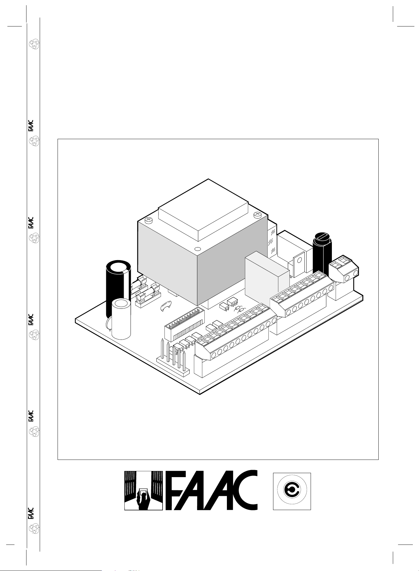
460-P
460-P
pour la nature
papier recyclé 100%
for nature
recycled paper 100%
per la natura
M
R
E
E
T
C
A
Z
I
E
N
D
UNI EN ISO 9001-085
A
C
I
F
A
I
T
C
R
E
A
T
carta riciclata 100%
Page 2

EC MACHINE DIRECTIVE COMPLIANCE DECLARA TION
Manufacturer: FAAC S.p.A.
Address: Via Benini, 1
40069 - Zola Predosa
BOLOGNA - ITALY
Hereby declares that: The electronic control unit model 460P
•complies with the essential safety requirements of the following directives :
73/23/EEC and subsequent amendment 93/68/EEC.
89/336/EEC and subsequent amendment 92/31/EEC and 93/68/EEC
ENGLISHENGLISH
Additional note:
These products have undergone tests in a typical uniform configuration (all
products manufactured by FAAC S.p.A.).
Bologna, 1 January 1997
Managing
Director
A. Bassi
15
Page 3

ENGLISH ENGLISH
IMPORTANT NOTICE FOR THE INSTALLER
GENERAL SAFETY REGULATIONS
1) WARNING! FAAC strongly recommends to follow these instructions literally for the safety of persons. Improper
installation or misuse of the product will cause very serious damages to persons.
2) Packaging material (plastic, polystyrene etc.) is a potential hazard and must be kept out of reach of children.
Read the instructions carefully before installing the product.
3)
4) Keep these instructions for future reference.
5) This product has been designed and manufactured only for the use stated in this manual. Any other use not expressly
set forth will affect the reliability of the product and/or could be source of hazard.
6) FAAC S.p.A. cannot be held responsible for any damage caused by improper use or different from the use for which
the automation system is destined to.
7) Do not use this device in areas subject to explosion: the presence of flammable gas or fumes is a serious hazard.
8) Mechanical constructive elements must comply with UNI8612, CEN pr EN 12604 and CEN pr EN 12605 standards.
Countries outside the EC shall follow the regulations above besides their national normative references in order to offer
the utmost safety.
9) FAAC cannot be held responsible for failure to observe technical standards in the construction of gates and doors, or
for any deformation of the gates which may occur during use.
10) Installation must comply with UNI8612, CEN pr EN 12453 and CEN pr EN 12635.
The degree of safety of the automation must be C+E.
11) Before carrying out any operations, turn off the system’s main switch.
12) An omnipower switch shall be provided for the installation with an opening distance of the contacts of 3 mm or more.
Alternatively, use a 6A thermomagnetic breaker with multi-pole switching.
13 ) Ensure that there is a differential switch up-line of the electrical system, with a trip threshold of 0.03A.
14 ) Check that the earthing plant is in perfect condition and connect it to the metallic parts. Also earth the yellow/green wire
of the operator.
15 ) The automation is fitted with an anti-crush safety system that is a torque control device. In any case, further safety devices
shall be installed.
16) The safety devices (e.g. photocells, safety edges etc.) protect areas wherethere is a mechanical movement hazard,
e.g. crushing, entrapment and shearing.
17) Each installation must be fitted with at least one flashing light (e.g. FAAC LAMP, MINILAMP etc.) as well as a warning plate
suitably fixed to the gate, besides the safety devices as per point 16. above.
18) FAAC cannot be held responsible regarding safety and correct functioning of the automation in the event that parts other
than FAAC original parts are used.
19) Use only FAAC original spare parts for maintenance operations.
20) Do not carry out any modifications to automation components.
21) The installer must supply all information regarding manual operation of the system in the event of an emergency and
provide the end-user with the “End-user Guide” attached to the product.
22) Keep out of persons when the product is in operation.
23) Keep out of reach of children the remote radio controls and any control devices. The automation could be operated
unintentionally.
24) The end-user must avoid any attempt to repair or adjust the automation personally. These operations must be carried
out exclusively by qualified personnel.
25) What is not explicitly stated in these instructions is not permitted.
16
Page 4
ENGLISHENGLISH
1. DESCRIPTION
The 460P is a microprocessor-based programmable electronic control unit for hydraulic operators constructed in SMT technology.
It is supplied in a standard configuration which can be modified using the FAACTOTUM programmer.
1.1 TECHNICAL SPECIFICATIONS
Table 1 460P hardware characteristics
Power supply 230 V ~ (+6% -10%) - 50 Hz
Max. absorbed power 35 W
Max. motor load 800 W
Accessories power supply 24 Vdc
Max. accessories load 0.5 A
Warning light power supply 24 Vdc
Max. warning light load 3 W
Temperature range -20°C +55°C
Fuses Motors power supply
Accessories power supply
Logic power supply
Mains filter Integrated in card
Quick connector For decoding cards/RP Receiver
Connector For FAACTOTUM and optional modules
Terminal block outputs Motor 1
Motor 2
Flashing light
Warning light power supply
Accessories power supply
Terminal block Removable
Table 2 Default programming characteristics
Terminal block inputs Open
Open single leaf
Stop
Closure safeties
Opening safeties
Operating logic Automatic
Opening/closing time 25 seconds
Pause time 25 seconds
Closing leaf delay time 5 seconds
Opening leaf delay time 2 seconds
Table 3 Accessories for 460P
FAACTOTUM for card programming
GATECODER deceleration/anti-crushing safety
Optional modules MEI (input expansion module)
MEL1 (electric lock management 1)
MEL2 (electric lock management 2)
1.2 PROGRAMMABLE PARAMETERS
Table 4 Parameters that can be programmed with FAACTOTUM
Operating logics: A-E-S-EP-P-B-C-B/C or customised
Safety operating logics
Warning light operating logics
Programmable warning light output
Available configurable outputs: Single leaf opening / Complete opening
Stop
Close
Opening/closing safeties
Panic device
Opening/closing safety edge
Leaf 1 and leaf 2 opening/closing limit switch
Gatecoder
Programming for operation with TIMER
Pre-flashing for opening and/or closing
Independent opening/closing times for each motor
Pause times
Opening/closing leaf delay
Failsafe on safeties
Electric lock opening/closing management
Over pushing stroke during opening and/or closing
Inversion stroke during opening and/or closing
Electronic deceleration: timed
with limit switches
with Gatecoder
The 460P electronic control unit can be installed using the
standard configuration and settings the card is supplied with
(characteristics are given in Table 2).
The FAACTOTUM programmer must be used if the default
configuration requires modification. By using FAACTOTUM it is
possible to modify an extremely wide range of parameters to
customise card operation according to the requirements and
characteristics of the automation.
FAACTOTUM also has a diagnostic function (signalling on the
display the state of the gate and inputs in real time and the
voltage levels on the card) and verifies operation of the
automation and the cycle counts performed.
For details on operation and programming of the FAACTOTUM
refer to its instruction manual.
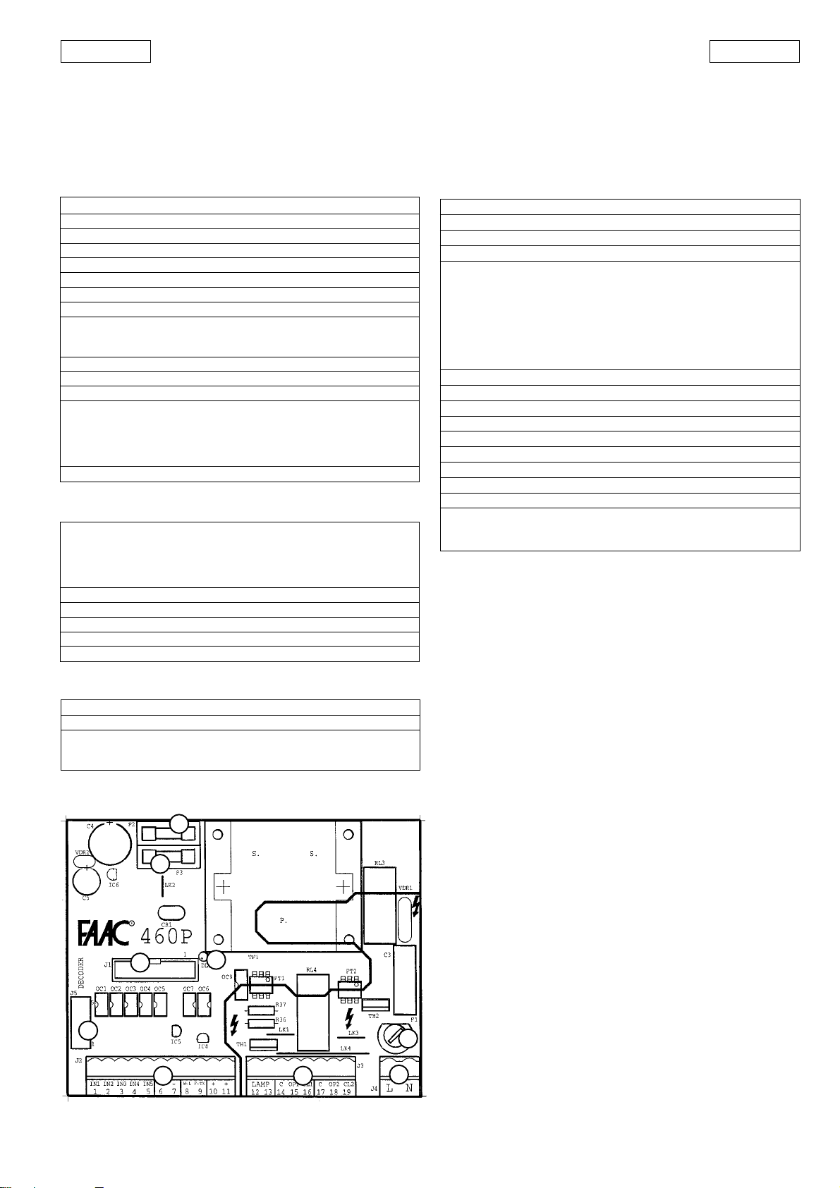
1.3 LAYOUT
8
9
aa
a Low-tension terminal block J2 is used to connect the
aa
activating devices and the accessories.
bb
b High-tension terminal block J3 is used to power the motors
5
6
7
bb
and the flashing light.
cc
c High-tension terminal block J4 is used for line voltage input.
cc
dd
d Fuse F1 5x20 5A/250V rapid powers motors and transformer
dd
primary coil.
ee
e Fuse F2 5x20 1.6A/250V delayed powers accessories.
ee
ff
f Fuse F3 5x20 315mA/250V delayed powers logic
ff
gg
g LED DL1 indicates the card power supply (lights up) and any
gg
variations in the state of each input (goes out momentarily)
hh
h Connector J1 for inserting optional modules and/or cable
hh
for connection to FAACTOTUM.
ii
i Connector J5 for quick connection of DECODER,MINIDEC, RP
ii
receiver.
4
1
2
3
Fig. 1
17
Page 5
ENGLISH ENGLISH
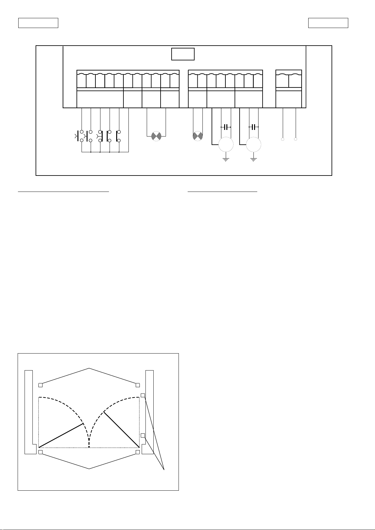
2. ELECTRICAL CONNECTIONS USING STANDARD CONFIGURATION
460P
FSW CL
STOP
OPEN-A
OPEN-B
FSW OP
WARNING
LIGHT
J3
J4
J2
W-L
F-TX
IN1
IN2 2IN4 4IN5
IN3
1
3
5
-
-
7
8
6
9
+
10
+
11
LAMP
12 13
C OP1 CL1
14 15 16
C OP2 CL2
17 18 19
L N
24 Vdc
3 W max
Terminal block J2 (low tension)
1 - IN1 = OPEN-A command - complete opening (N.O.)
This means any device (pushbutton, detector,
etc.) which can give an opening/closing pulse
for both gate leaves through the closure of a
contact.
To install more than one OPEN-A device
connect the N.O. contacts in parallel.
2 - IN2 = OPEN-B command - single leaf opening (N.O.)
This means any device (e.g. pushbutton) which
can give an opening/closing pulse for the gate
leaf driven by motor M1 through the closure of
a contact.
To install mor e than one OPEN-B device connect
the N.O. contacts in parallel.
3 - IN3 = STOP command (N.C.)
This means any device (e.g. pushbutton) which
stops the movement of the gate by opening a
contact.
To install more than one stop device connect
the N.C. contacts in series.
Ü If Stop devices are not connected jumper
the input with the common contact
(terminal 6 or 7).
Opening/closing photocells
FAAC LAMP
MINILAMP
BLU
BLUE
C1
M1
BLU
BLUE
C2
M2
230 Vac
50 Hz
Fig. 2
Note about safety devices
These are all devices (photocells, safety edges, magnetic coils,
etc.) with an N.C. contact which are activated if an obstacle
obstructs the area protected by the safety devices and stop the
movement of the gate leaves (fig. 3).
Ü If the opening safety devices are activated when the gate
is closed, they prevent the leaves from opening.
If the closing safety devices are activated when the gate
is open, they prevent the leaves from closing.
4 - IN4 = FSW-CL Closing safety device contact (N.C.)
During closure, activation of the safety devices
causes the gate leaves to reverse their direction
of movement. They are not activated during
opening.
Ü If closure safety devices are not connected,
jumper this input to the common contact
(terminal 6 or 7).
The function of the closure safety devices is
to safeguard the area affected by the
movement of the leaves during closure (B,
fig. 3).
5 - IN5 = FSW-OP Opening safety device contact (N.C.)
During opening the safety devices stop the
movement of the gate leaves. When released
they reverse the direction of movement.
Ü If opening safety devices are not connected,
jumper this input with the common contact
(terminal 6 or 7).
The function of the opening safety devices
is to safeguard the area behind the gate
leaves (A, fig. 3).
Fig. 3
A
B
Closing photocells
It is possible to connect devices which operate simultaneously
as opening and closing safety devices (see example of safety
device connection).
A
A
The gate leaves stop if these safety devices are activated during
opening, then carry on opening when they are released.
B
The leaves stop moving if these safety devices are activated
during closure, then change direction and open when they are
released.
Fig. 3 shows a recommended example of safety device installation.
Opening
photocells
18
Page 6

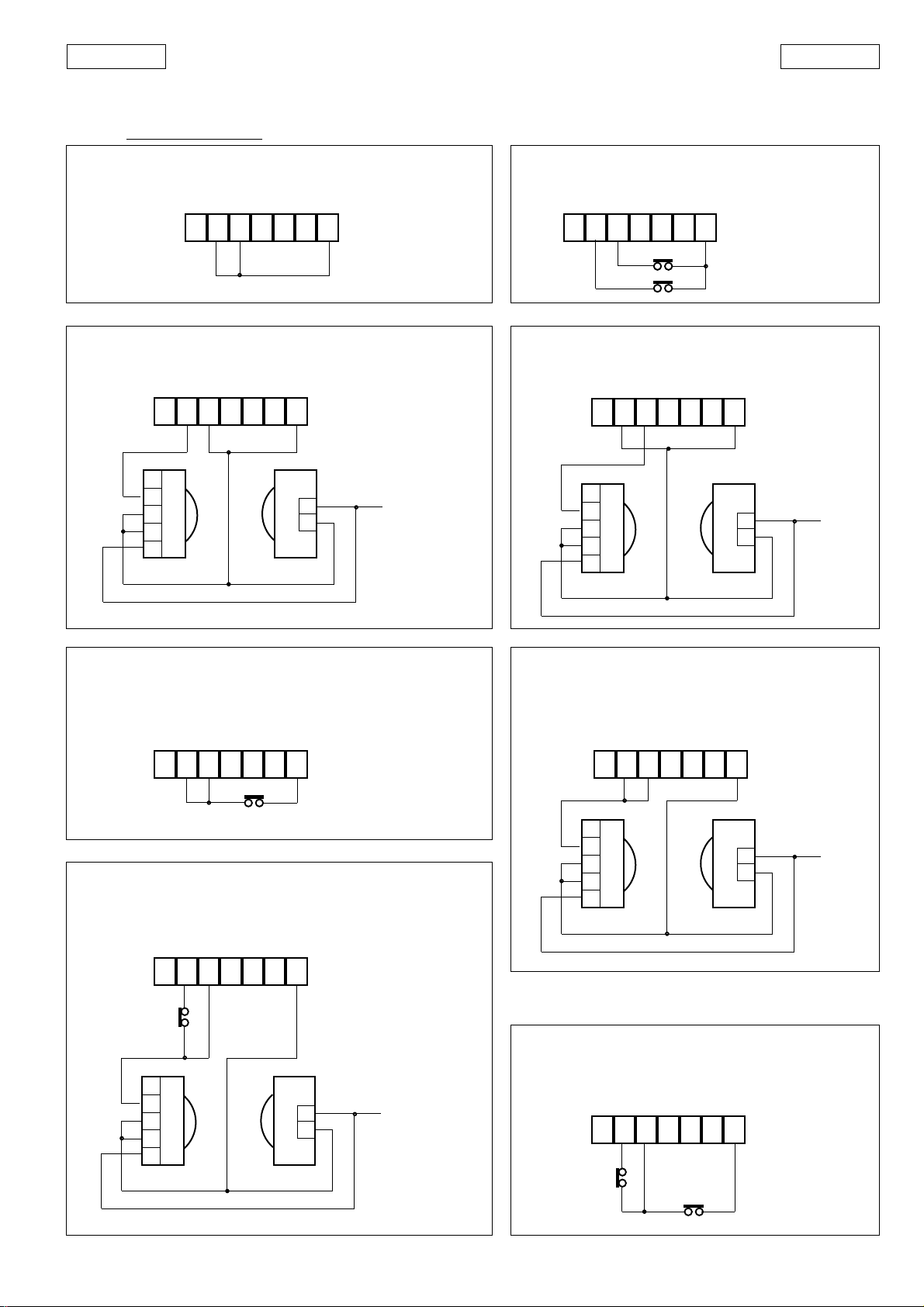
Examples of application of safety devices and connections
(using the 460P standard configuration)
Ü FAILSAFE disabled
ENGLISHENGLISH
No safety device connected
IN4 IN5
6 7 10 11
FSWCLFSW
OP
- - + +
J2
One pair of closure photocells connected
IN4 IN5
FSWCLFSW
1
2
3
4
5
7 6 10 11
OP
- - + +
J2
2
1
TXRX
Fig. 4
One pneumatic safety edge connected as closure safety
device and once connected as opening safety device
IN4 IN5
FSWCLFSW
7
6 10 11
OP
- - + +
J2
Fig. 5
One pair of opening photocells connected
IN4 IN5
FSWCLFSW
1
2
3
4
5
7 6 10 11
OP
- - + +
TXRX
J2
2
1
Fig. 6
One pair of closure photocells and one pair of opening
photocells connected
IN4 IN5
FSWCLFSW
1
2
3
4
5
RX CL
2
1
TX OP
7 6 10 11
OP
- - + +
TX CL
RX OP
J2
2
1
1
2
3
4
5
One pair of closure photocells and one pair of
opening/closure photocells connected
IN4 IN5
FSWCLFSW
1
2
3
4
5
RX CL
2
1
TX OP/CL
7 6 10 11
OP
- - + +
TX CL
RX OP/CL
J2
2
1
1
2
3
4
5
Fig. 7
Fig. 8
Fig. 9
19
Page 7

ENGLISH ENGLISH
6 and 7
- Accessories power supply Common/Negative (-)
8 - Warning Light (-)
Warning light power supply negative.
The warning light (24 Vdc 3 W max.) must be
inserted between this terminal and the positive of
the accessories power supply (terminal 10 or 11).
Do not exceed the stated power.
Table 5: Warning light standard operation
GATE STATE CLOSED OPEN ON P AUSE CLOSING OPENING STOPPED
WARNING LIGHT Off O n Flashing O n On
Ü The FAACTOTUM can be used to program operation of the
warning light output:
Warning light steady during closure
1)
6) Closing state
2) Courtesy timing 7) Closed state
3) Panic device active 8) Stop command active
4) Open state 9) Pause state
5) Opening state
9 - F-TX (-)
If the FAILSAFE is used (programming it with the FAACTOTUM), this
terminal constitutes the power supply negative for the photocell
transmitter.
10 and 11 - Accessories power supply positive (+24 Vdc)
The maximum accessories load is 500 mA. To calculate absorbed
power, refer to table 6.
Table 6 Accessories consumption
TYPE OF ACCESSORY NOMINAL DRAWN CURRENT
R 31 50 mA
PLUS 433 E 20 mA
MINIDEC SL / DS 6 mA
DECODER SL / DS 20 mA / 55 mA
RP 433 SL / DS 12 mA / 6 mA
DIGICARD 15 mA
METAL DIGIKEY 15 mA
FOTOSWITCH 90 mA
DETECTOR F4 / PS6 50 mA
MINIBEAM 70 mA
WARNING LIGHT 150 mA
Terminal block J4 (high-tension input)
L - 230 V ac pow er supply (Live)
N - 230 V ac power supply (Neutral)
Connector J5
Connector J5 (9, fig. 1) is used for quick connection of DECODER,
MINIDEC and RP Receiver (Figs. 10, 11, 12, 13).
Connect by inserting the connector on the accessories cards
perpendicularly to the corresponding connector J5 on the
460P.
Turn off the power supply at the electronic control unit before
connecting and disconnecting.
PLUS
460 P
460 P
MINIDEC
SL/DS
Fig. 10
460 P
DECODER
SL
Fig. 11
Terminal block J3 (high-tension outputs)
12 and 13
14,15,16 - COM/OP1/CL1 = MOTOR 1
17,18,19 - COM/OP2/CL2 = MOTOR 2
- LAMP (230Vac)
Terminals for connecting the flashing light
(FAAC Lamp, Minilamp)
Connection of
Motor 1 (delayed closure)
COM = motor common (blue cable)
OP1/CL1 = motor phases
Motor 1 is activated in single-leaf opening
Use this output for the single-leaf application
Connection of
Motor 2 (delayed opening)
COM = motor common (blue cable)
OP2/CL2 = motor phases
N.B. Use a dedicated decoder for each accessory type.
Fig. 12
460 P
Fig. 13
20
Page 8

ENGLISHENGLISH
Connector J1
Optional modules (MEI - MEL1 - MEL2) and/or the FAACTOTUM
connection cable must be inserted in connector J1 (Fig. 14).
The connector can be fitted one way only so that the module
terminal block is oriented in the same direction as the 460P card
terminal block. Disconnect power from the card before inserting
or removing the modules.
4. OPTIONAL MODULES
The optional modules are additional electronic cards installed
on the 460P.
Each module has two connectors: one on the soldered side, the
other on the component side.
The connector on the soldered side allows the module to be
inserted into card 460P connector J1 or into the connector on
the component side of another module.
The connector on the component side can be used to fit
another module or the FAACTOTUM connection cable into the
module.
The currently available modules are:
MEL-1 : single electric lock management module.
MEL-2 : double electric lock management module.
MEI : input expansion module.
The electric lock management modules must not both be
installed on the same 460P card.
One input expansion module (MEI) and one electric lock
management module (MEL-1 or MEL-2) can be installed, bearing
the following in mind:
The MEI module must be fitted into the 460P card connector J1
and the electric lock management module must be fitted on
top of the MEI module.
The connecting cable to the FAACTOTUM must be inserted into
the 460P card connector J1 if it is free (i.e. when no other
optional module is installed) or into the free connector of the
last installed module.
Fig. 14
3. INSTALLATION
Install the electronic control unit in enclosures with adequate
housing protection (min. IP55).
The cable holes and tube grips used for wiring must not reduce
the housing protection of the enclosure.
The 460P is provided with standard preset programming (the
characteristics are given in Table 2). For details of operation,
refer to Table 9.
Ü The inputs CLOSE, SAFE-OP, SAFE-CL and EMERG are
available only by installing the input expansion module MEI
on the card (it is not necessary to program with the
FAACTOTUM).
3.1 CHECKING DIRECTION OF ROTATION
1) Turn off power supply to 460P card.
2) Move the gate or barrier manually to its halfway open
position.
3) Lock the operators again.
4) Turn the power supply back on.
5) Send an opening pulse and check that this opens the leaf
or the barrier.
If the first opening pulse closes one or both leaves, invert the
electric motor phases (brown and black cables) on the card
terminal block for each leaf that closes.
Module MEL-1
The module MEL-1 (Fig. 15) is able
to control either just one electric
lock or a number of electric locks
activated simultaneously (using
an external power supply). A free
contact is available between
terminals 3 (COM) and 4 (N.O.).
In the connection diagram shown
in Fig. 16, just one 12 Vdc electric
lock with 12 ohm internal
resistance must be installed.
A different type of electric lock or
a number of electric locks in
parallel can be installed using an
adequate external power supply
as shown in the diagram in Fig. 17.
In this case do not exceed the
maximum permitted contact
capacity (5A max.).
Ü The MEL-1 module can be installed on the 460P card
without it being necessary to perform any programming
when using a
closure electric lock.
Fig. 15
MEL-1
+
-
1 2 3 4
1:negative
2:positive
3:free common contact
4:N.O. free contact
EL : 12Vdc 12 ohm electric lock
+-
EL
Fig. 16
21
Page 9

ENGLISH ENGLISH
MEL-1
+
-
1 2 3 4
Closing the contact between terminals 3-4 activates the electric
lock(s) present.
With the FAACTOTUM it is possible to program this contact to
close as follows:
- only when the gate starts to open
- only when the gate starts to close
- when the gate starts to open and when it starts to close.
Module MEL 2
The module MEL-2 (Fig. 18) is able
to control 2 inputs for
independent electric locks. Two
free contacts are available
between terminals 3 (COM), 5
(N.O.) and 6 (N.O.).
Following the connection
diagram shown in Fig. 19, a
maximum of two 12 Vdc electric
locks with 12 ohm internal
resistance can be installed.
It is possible to install different
types of electric locks or a number
of electric locks in parallel using
external power sources following
the connection diagram shown
in Fig. 20.
In this case do not exceed the
maximum allowed capacity of
the contacts (2 A max.).
Single-leaf automation
In single-leaf automation the closure electric lock (Fig. 19) or
electric locks (Fig. 20) must be connected to terminal 6, while
the opening electric lock (Fig. 19) or electric locks (Fig. 20) must
be connected to terminal 5.
Double-leaf automation
In double-leaf automation the electric lock (Fig. 19) or electric
locks (Fig. 20) of leaf 1 (connected to motor M1) must be
connected to terminal 6, while the electric lock (Fig. 19) or
electric locks (Fig. 20) of leaf 2 (connected to motor M2) must
be connected to terminal 5.
Closing the contacts between terminals 3-5 and 3-6 activates
the electric lock(s) connected to them.
By using the FAACTOTUM these contacts can be programmed
to close as follows:
- only when the gate starts to open
- only when the gate starts to close
- when the gate starts to open and when it starts to close.
N.B. the maximum capacity
of the free contact is 5A.
External power
supply
EL 2
EL1 - EL2 :
Electric locks
EL 1
Fig. 17
Fig. 18
MEL-2
+
-
1 2 3
-
5
6
+
EL 2
-
+
EL 1
MEL-2
+
-
1 2 3
MEI module
The MEI module (Fig. 21) is an
electronic input expansion card.
It must be inserted in the 460P
card connector J1. It must not be
installed on top of any electric
lock management modules
already present in the connector
J1.
On the MEI module there are 6
additional inputs with respect to
the standard 5 of the 460P
electronic card described above.
EL 1
EL 2
EL 3
EL 4
5
6
1: negative
2: positive
3: free common contact
5: free contact (N.O.)
6: free contact (N.O.)
EL 1 - EL 2 :
12Vdc 12ohm electric locks
Fig. 19
N.B.: the maximum
capacity of the
contacts is 2A.
V2
V1
V1 - V2 :
External power
supplies
EL1-EL2-EL3-EL4 :
Electric locks
Fig. 20
Fig. 21
22
Page 10

ENGLISHENGLISH
MEI
CLOSE
IN6 IN7 IN 8 IN 9 IN10 IN11
The MEI module can be installed without any need for
programming (except for the inputs reserved for the Gatecoder/
Limit Switch, which must be configured). Be sure to observe the
allocation of the default inputs below:
IN6 - CLOSE = Closure command (N.O.)
This means any device (e.g. pushbutton) which
gives a command to close the leaf/leaves when
a contact is closed in “deadman” logic. In the
other logics, when the gate is open, on pause
or stopped, it gives the command to close the
leaf/leaves while it is inactive with the gate
closed or opening.
IN7 - SAFE CL = Safety edge closing (N.C.)
This input is specifically for connecting
pneumatic safety edges which intervene
during the closure phase.
Opening this contact during the closure phase
causes timed inversion (2 sec. subject to
modification) and then stops the movement.
Ü If no devices are connected, jumper this
input to the negative (terminal “-” of MEI
module if the Failsafe is disabled, terminal 9
of 460P if the Failsafe is enabled).
IN8 - SAFE OP = Safety edge opening (N.C.)
This input is specifically for connecting
pneumatic safety edges which intervene
during the opening phase.
Opening this contact during the opening phase
causes timed inversion (2 sec. subject to
modification) and then stops the movement.
Ü If no devices are connected, jumper this
input to the negative (terminal “-” of MEI
module if the Failsafe is disabled, terminal 9
of 460P if the Failsafe is enabled).
It is possible to connect devices which activate
simultaneously , such as opening and closing safety
edges (see connection examples in section 8).
If these safety devices activate during opening or
closing, they stop the gate.
For details of operation, ref er to T able 9.
IN 9 - EMERG = Panic device (N.C.)
This means any device (e.g. pushbutton) which
immediately opens the gate or barrier when a
contact is opened regardless of the state of
the other inputs.
Once the panic opening command has been
given, normal operation can be resumed only
by resetting the contact and turning the
electronic control unit off and then back on
again.
Ü If no devices are connected, jumper this
input to the negative (terminal “-” of MEI
module).
SAFE-OP
SAFE-CL
EMERG
-
Fig. 22
IN10 -
GC1/FCA1 = Gatecoder 1 / Opening limit switch 1
This input varies according to the programming
performed (use of Gatecoder or Limit switch):
Gatecoder used
This is the input for the signal coming from the
Gatecoder installed on the leaf connected to
the motor M1 (LEAF 1).
Limit switch used
Input for Leaf 1 opening limit switch contact.
The limit switch is a device with an N.C. contact
which slows down the leaf connected to motor
M1 (LEAF 1) if the contact opens during the leaf
opening phase.
= GC1
= FCA1 (N.C.)
Gatecoder and Limit switch not used
In this case the input is not active.
IN 11 -
GC2/FCC1 = Gatecoder 2 / Closure Limit Switch 1
This input varies according to the programming
performed (use of Gatecoder or Limit switch):
Gatecoder used
This is the input for the signal coming from the
Gatecoder installed on the leaf connected to
motor M2 (LEAF 2).
Limit switch used
Input for Leaf 1 closure limit switch contact.
The limit switch is a device with an N.C.
contact which slows down the leaf connected
to motor M1 (LEAF 1) if the contact opens
during the leaf opening phase.
= GC2
= FCC 1 (N.C.)
Gatecoder and Limit switch not used
In this case the input is not active.
5. GATECODER
The Gatecoder is an electronic detector that reads in real time
the exact position of the leaf for the gate on which it is installed.
Two-leaf gates require a Gatecoder for each leaf.
The GATECODER is compatible only with the 460P card.
Table 7 GATECODER technical characteristics
Power supply 24Vdc
Housing protection IP 66
Ambient temperature -20 °C +55 °C
Connection to 460P 3x0.35 mm2 cable length 1 metre
Functions Deceleration/anti-crushing
Installable on operators 402-422-400
By using a learning cycle during the 460P card programming
phase, the Gatecoder slows down the leaf at the desired point
during both closing and opening.
Furthermore the Gatecoder also constitutes an effective
electronic anti-crushing safety device (which can be disabled)
because if an obstacle is detected while the leaf is moving it
reverses the direction of movement.
The obstacle detection time before reversal of movement is
programmable (standard 1 sec.).
5.1 INSTALLATION
Refer to Fig. 23.
1) 1) Insert the Gatecoder support fork (1) into the operator
fitting rear bracket. The tongue (2) must be facing the post.
2) Fit the operator support fork to the bracket, inserting the pin
(4) in such a way that the hexagonal part of the pin engages
in the hexagonal seat on the fork. Lock by tightening the nut.
3) Thread the connecting cable (6) through the hole on the
bracket as shown in the diagram.
4) Insert the GATECODER pin into the long pin housing, making
sure that the flat part is matched up with the securing dowel
(5).
At the same time insert the tongue (2) on the fork (1) into the
Gatecoder housing.
23
Page 11

ENGLISH ENGLISH
5) Tighten the dowel (5).
6) Connect the GATECODER to the 460P card.
Ü Even if the Gatecoder is used, opening and closing mechanical
stops are required for correct operation of the automation.
2
5
1
6
Rosso/Red/Rouge/Rot/Rojo = +24 Vdc
Nero/Black/Noir/Schwarz/Nigro = –
Blanco/White/Blanc/Weiß/Blanco = GC1/GC2
3
4
Fig. 23
6. INPUT MANAGEMENT (requires FAACTOTUM)
The 460P is able to control the following inputs:
Ü Limitations in assigning of inputs:
1) The terminal IN1 (OPEN-A) does not appear in the assigning
cycle because it cannot be changed.
2) Terminals IN2-IN5 can be assigned different functions to the
default functions, chosen from inputs nos. 6-13 given in
table 8.
3) Limit switches cannot be used at the same time as the
Gatecoder and vice versa.
4) With the sole exception given below, it is not possible to
assign the same function to more than one terminal.
5) The 460P card terminal IN2 can also be configured as a
second OPEN-A input so that if an opening control device
shorts on one of the two inputs, the devices connected to
the other input continue to control the automation as
normal.
6) It is not possible to move an input which already has an
assigned default terminal on the 460P card (e.g. the STOP
function cannot be assigned to terminal IN5 on the 460P
card).
7) Each terminal, with the exception of IN1 and IN2, can be
deactivated by selecting the “INACT” function in the input
assigning cycle.
460P with MEI module
The 5 inputs on the 460P card plus the 6 inputs o the MEI module
available by default are shown in Fig. 25.
Table 8
No. Input Description Type
1 OPEN-A total leaf opening N.O.
2 OPEN-B single leaf opening N.O.
3 STOP stops movement N.C.
4 FSW-CL closure safety photocells N.C.
5 FSW-OP opening safety photocells N.C.
6 CLOSE closure command N.O.
7 SAFE-CL closure safety edge N.C.
8 SAFE-OP opening safety edge N.C.
9 EMERG panic device N.C.
10/a GC1 Gatecoder leaf 1 signal
11/a GC2 Gatecoder leaf 2 signal
10/b FCA1 leaf 1 opening limit switch N.C.
11/b FCC1 leaf 1 closing limit switch N.C.
12 FCA2 leaf 2 opening limit switch N.C.
13 FCC2 leaf 2 closing limit switch N.C.
Ü Leaf 1 is the leaf connected to motor M1
Leaf 2 is the leaf connected to motor M2
On the 460P and the MEI module the terminal block inputs are
assigned by default.
The FAACTOTUM can be used during the programming phase
to change the assigned inputs according to the rules given
below.
460P without MEI module
The 5 inputs on the 460P card available by default are given in
Fig. 24.
460P
STOP
OPEN-B
OPEN-A
IN1 IN2 IN3 IN4 IN5
J2
FSW-OP
FSW-CL
Fig. 24
460P
STOP
OPEN-B
OPEN-A
IN1 IN2 IN3 IN4 IN5
J2
FSW-OP
FSW-CL
MEI
CLOSE
SAFE-CL
IN6 IN7 IN8 IN9 I
J1
SAFE-OP
EMERG
N10
GC2/FCC1
GC1/FCA1
IN11
Fig. 25
The inputs IN6-IN9 are active without the need for programming
using the FAACTOTUM. Simply insert the MEI module into the
460P with the standard configuration.
Ü Limitations in assigning of inputs:
1) The terminal IN1 (OPEN-A) does not appear in the assigning
cycle because it cannot be changed.
2) Terminals IN10-IN11 do not appear in the assigning cycle
because they are set directly by the FAACTOTUM according
to the selections made during programming (use of
Gatecoder or limit switches). If neither the Gatecoder or
the limit switches are used they are inactive.
3) If the limit switches are used, terminals IN2-IN9 can be
assigned different functions to those set by default, chosen
among inputs 12-13 given in table 8.
4) Limit switches cannot be used at the same time as the
Gatecoder and vice versa.
5) With the sole exception given below, it is not possible to
assign the same function to more than one terminal.
6) The 460P card terminal IN2 can also be configured as a
second OPEN-A input so that if an opening control device
shorts on one of the two inputs, the devices connected to
the other input continue to control the automation as
normal.
7) It is not possible to move an input which already has an
assigned default terminal on the 460P card or the MEI
module (e.g. the STOP function cannot be assigned to
terminal IN5 on the 460P card).
8) Each terminal, with the exception of IN1, IN2, IN10 and IN11,
can be deactivated by selecting the “INACT” function in the
input assigning cycle.
24
Page 12

Table 9 Standard automatic operating logic
LOGIC “A” PULSES
GATE STATUS
OPEN-A
OPEN-B
CLOSE
STOP
FSW-OP
FSW-CL
FSW-OP/CL
SAFE-OP
SAFE-CL
SAFE-OP/CL
CLOSED
OPENING
OPEN ON
PAUSE
CLOSING
STOPPED
opens leaves and
recloses after pause
time
no effect (1)
recloses leaves
immediately (1)
reopens leaves
immediately
closes the leaves (1)
opens single leaf and
recloses after pause
time
no effect
recloses leaf/leaves
immediately
reopens leaf/leaves
immediately
closes the leaf/leaves
no effect
no effect
recloses leaf/leaves
immediately
no effect
closes leaf/leaves
no effect
(OPEN inhibited)
stops
stops
stops
no effect
(OPEN/CLOSE inhibited)
no effect
(OPEN inhibited)
stops opening and
when disengaged
closes
no effect
-opening inhibited-
no effect
no effect
-opening inhibited-
Ü The effects of an active impulse on the other inputs is given in brackets.
25
(1) An OPEN-A impulse during a pedestrian cycle (OPEN-B), activates both leaves in opening.
(2) If residual pause time is shorter than 5 seconds, it closes after 5 seconds when the safeties are disengaged.
no effect
no effect
freezes pause until
disengagement
-closure inhibited-
changes direction and
starts to open
no effect
-closure inhibited-
no effect
(OPEN inhibited)
stops opening and
when disengaged
continues to open
freezes pause until
disengagement (2)
-OPEN/CLOSE inhibited-
stops and when
disengaged starts to
open
no effect
(OPEN/CLOSE inhibited)
no effect
(OPEN inhibited)
reverses movement for
2 seconds then stops
no effect
-opening inhibited-
no effect
no effect
-opening inhibited-
no effect
no effect
no effect
-closure inhibited-
reverses movement for
2 seconds then stops
no effect
-closure inhibited-
no effect
(OPEN inhibited)
stops movement
➲ when disengaged
OPEN= closes (1)
CLOSE= closes
no effect
(OPEN/CLOSE inhibited)
stops movement
➲ when disengaged
OPEN= opens
CLOSE= closes
no effect
(OPEN/CLOSE inhibited)
ENGLISHENGLISH
Page 13

ENGLISH ENGLISH
7. FAILSAFE
FAILSAFE is a system for checking the functionality of the photocells.
The check is always performed before the motors are started. It turns off the power supply temporarily to the photocell transmitter
and checks that this causes the contact on the receiver to open. If it does not, movement of the leaves is inhibited for safety reasons.
To enable the FAILSAFE it must be set during the programming phase.
Using the FAILSAFE requires a separate power supply for the photocell transmitter (see Figs. 26, 27, 28, 29, 30, 31)
Examples of applications of safety devices and connections
(with FAILSAFE enabled on inputs FSW-CL and FSW-OP)
No safety device connected
IN4 IN5
6 7 10 11
FSWCLFSW
OP
- - + +
-
9
J2
Connection of a pair of closure photocells
7 6 10 11
9
- J2
J2
2
1
1
2
3
4
5
IN4 IN5
FSWCLFSW
OP
- - + +
TXRX
Fig. 26
Fig. 28
One pneumatic safety edge connected as a closure
safety device and one as an opening safety device
IN4 IN5
FSWCLFSW
7
6 10 11
OP
- - + +
9
-
J2
Fig. 27
Connection of a pair of opening photocells
7 6 10 11
9
-
2
1
1
2
3
4
5
IN4 IN5
FSWCLFSW
OP
- - + +
TXRX
Fig. 29
Connection of one pair of closure photocells and
one pair of opening photocells
IN4 IN5
FSWCLFSW
1
2
3
4
5
RX CL
2
1
7 6 10 11
9
OP
- - + +
-
TX CL
J2
2
1
1
2
3
4
5
RX OPTX OP
Connection of one pair of closure photocells and
one pair of opening/closure photocells
IN4 IN5
FSWCLFSW
1
2
3
4
5
7 6 10 11
9
OP
- - + +
-
J2
2
1
RX CL TX CL
1
2
1
2
3
4
5
RX OP/CLTX OP/CL
Fig. 30
Fig. 31
26
Page 14
8. CONNECTION EXAMPLES ON SAFE-OP AND SAFE-CL INPUTS
(using 460P standard configuration and MEI module)
➲ FAILSAFE disabled
No safety device connected
IN8
IN7
SAFECLSAFE
OP
-
MEI
An opening pneumatic safety edge (SAFE OP)
and a closing pneumatic safety edge (SAFE-CL)
connected
IN8
IN7
SAFECLSAFE
OP
OP
ENGLISHENGLISH
MEI
-
CL
A pair of photocells connected to SAFE-CL
input
IN8
IN7
SAFECLSAFE
OP
1
2
3
4
5
CL
RX
-
TX
2
1
MEI
➩➩
➩
➩➩
An opening/closing pneumatic safety edge
connected (SAFE OP/CL)
IN8
IN7
SAFECLSAFE
OP
-
MEI
+24Vdc
(Vacc)
A pair of photocells connected to SAFE-OP
input
IN8
IN7
SAFECLSAFE
OP
1
2
3
4
5
OP
RX
-
TX
MEI
2
1
A pair of opening/closing photocells
connected (SAFE OP/CL)
IN8
IN7
SAFECLSAFE
OP
-
MEI
+24Vdc
➩➩
➩
➩➩
(Vacc)
OP/CL
A closing pneumatic safety edge (SAFE CL) and
a pair of opening/closing photocells (SAFE OP/
CL) connected
IN8
IN7
SAFECLSAFE
OP
CL
1
2
3
4
5
OP/CL
RX
-
TX
MEI
2
1
➩➩
➩
➩➩
+24Vdc
(Vacc)
27
1
2
3
4
5
RX
OP/CL
TX
2
1
+24Vdc
➩➩
➩
➩➩
(Vacc)
A closing pneumatic safety edge (SAFE CL) and
an opening/closing pneumatic safety edge
(SAFE OP/CL) connected
IN8
IN7
CL
SAFECLSAFE
OP
OP/CL
-
MEI
Page 15

ENGLISH ENGLISH
R
SYSTEM CONFIGURATION
INPUT STANDARD Customised
N°
No. assigning assigning
INGRESSO
Assegnazione
STANDARD
Assegnazione
Personalizzata
1 O PEN-A OPEN-A
Tempo pausa
Pause time
OP. delay time
Tempo ritardo AP.
CL. delay time
Tempo ritardo CH.
2OPEN-B
3STOP
460PMEI
4FSW-CL
5FSW-OP
6CLOSE
7SAFE-CL
8SAFE-OP
9EMERG
10 /
11 /
Programming Name:
Opening pre-flashing
Closure pre-flashing
Opening inversion stroke
Closure inversion stroke
Standard logic :
AS EEP P
B
C
Customised
logic :_____________
Failsafe :
FSW-CL FSW-OP
SAFE-CL SAFE-OP
Deceleration:
timed
with limit switch
with Gatecoder
Opening over pushing stroke
Closure
B/C
over pushing stroke
Installation date:_____________
Installer:____________________
Notes :
✄
28
Page 16

Le descrizioni e le illustrazioni del presente manuale non sono impegnative. La FAAC si riserva il diritto,
lasciando inalterate le caratteristiche essenziali dell’apparecchiatura, di apportare in qualunque
momento e senza impegnarsi ad aggiornare la presente pubblicazione, le modifiche che essa ritiene
convenienti per miglioramenti tecnici o per qualsiasi altra esigenza di carattere costruttivo o
commerciale.
The descriptions and illustrations contained in the present manual are not binding. FAAC reserves the
right, whilst leaving the main features of the equipments unaltered, to undertake any modifications
it holds necessary for either technical or commercial reasons, at any time and without revising the
present publication.
Les descriptions et les illustrations du présent manuel sont fournies à titre indicatif. FAAC se réserve le
droit d’apporter à tout moment les modifications qu’elle jugera utiles sur ce produit tout en conservant
les caractéristiques essentielles, sans devoir pour autant mettre à jour cette publication.
Die Beschreibungen und Abbildungen in vorliegendem Handbuch sind unverbindlich. FAAC behält
sich das Recht vor, ohne die wesentlichen Eigenschaften dieses Gerätes zu verändern und ohne
Verbindlichkeiten in Bezug auf die Neufassung der vorliegenden Anleitungen, technisch bzw.
konstruktiv/kommerziell bedingte Verbesserungen vorzunehmen.
Las descripciones y las ilustraciones de este manual no comportan compromiso alguno. FAAC se
reserva el derecho, dejando inmutadas las características esenciales de los aparatos, de aportar, en
cualquier momento y sin comprometerse a poner al día la presente publicación, todas las
modificaciones que considere oportunas para el perfeccionamiento técnico o para cualquier otro
tipo de exigencia de carácter constructivo o comercial.
para la naturaleza
100% papel reciclado
ist umweltfreundlich
100% Altpapier
FAAC per la natura
• La presente istruzione è realizzata al 100% in carta riciclata.
• Non disperdete nell'ambiente gli imballaggi dei componenti dell'automazione bensì selezionate
i vari materiali (es. cartone, polistirolo) secondo prescrizioni locali per lo smaltimento rifiuti e le
norme vigenti.
FAAC for the environment
• The present manual is produced in 100% recycled paper
• Respect the environment. Dispose of each type of product packaging material (card, polystyrene)
in accordance with the provisions for waste disposal as specified in the country of installation.
FAAC der Umwelt zuliebe
• Vorliegende Anleitungen sind auf 100% Altpapier gedruckt.
• Verpackungsstoffe der Antriebskomponenten (z.B. Pappe, Styropor) nach den einschlägigen
Normen der Abfallwirtschaft sortenrein sammeln.
FAAC écologique
• La présente notice a été réalisée 100% avec du papier recyclé.
• Ne pas jeter dans la nature les emballages des composants de l’automatisme, mais sélectionner
les différents matériaux (ex.: carton, polystyrène) selon la législation locale pour l’élimination des
déchets et les normes en vigueur.
FAAC por la naturaleza.
• El presente manual de instrucciones se ha realizado, al 100%, en papel reciclado.
• Los materiales utilizados para el embalaje de las distintas partes del sistema automático (cartón,
poliestireno) no deben tirarse al medio ambiente, sino seleccionarse conforme a las prescripciones
locales y las normas vigentes para el desecho de residuos sólidos.
FAAC S.p.A.
Via Benini, 1
40069 Zola Predosa (BO) - ITALIA
Tel.: 051/6172411 - Tlx.: 521087
Fax: 051/758518
pour la nature
papier recyclé 100%
for nature
recycled paper 100%
Timbro del Rivenditore:/Distributor’s Stamp:/Timbre de l’Agent:/ Fachhändlerstempel:/Sello del Revendedor:
per la natura
XXXXX - Rev.B
carta riciclata 100%
 Loading...