

Page 1
voor de natuur
100% kringlooppapier
para la naturaleza
100% papel reciclado
455D
455D
ist umweltfreundlich
100% Altpapier
pour la nature
papier recyclé 100%
for nature
recycled paper 100%
per la natura
carta riciclata 100%
Page 2
CE DECLARATION OF CONFORMITY
Manufacturer: FAAC S.p.A.
Address: Via Benini, 1 - 40069 Zola Predosa BOLOGNA - ITALY
Declares that: 455 D control board,
• conforms to the essential safety requirements of the following directives:
73/23/CEE and subsequent amendment 93/68/CEE.
89/336/CEE and subsequent amendment 92/31/CEE and 93/68/CEE
Additional note:
This product underwent tests in a typical uniform configuration
(all products manufactured by FAAC S.p.A.).
Bologna, 01 May 2005
The Managing Director
A. Bassi
WARNINGS FOR THE INSTALLER
GENERAL SAFETY OBLIGATIONS
1) ATTENTION! To ensure the safety of people, it is important that you read
all the following instructions. Incorrect installation or incorrect use of
the product could cause serious harm to people.
2) Carefully read the instructions before beginning to install the product.
3) Do not leave packing materials (plastic, polystyrene, etc.) within reach
of children as such materials are potential sources of danger.
4) Store these instructions for future reference.
5) This product was designed and built strictly for the use indicated in this
documentation. Any other use, not expressly indicated here, could
compromise the good condition/operation of the product and/or be a
source of danger.
6) FAAC declines all liability caused by improper use or use other than that
for which the automated system was intended.
7) Do not install the equipment in an explosive atmosphere: the presence
of inflammable gas or fumes is a serious danger to safety.
8) The mechanical parts must conform to the provisions of Standards EN
12604 and EN 12605.
For non-EU countries, to obtain an adequate level of safety, the Standards
mentioned above must be observed, in addition to national legal
regulations.
9) FAAC is not responsible for failure to observe Good Technique in the
construction of the closing elements to be motorised, or for any
deformation that may occur during use.
10) The installation must conform to Standards EN 12453 and EN 12445.
For non-EU countries, to obtain an adequate level of safety, the Standards
mentioned above must be observed, in addition to national legal
regulations.
11) Before attempting any job on the system, cut out electrical power .
12) The mains power supply of the automated system must be fitted with an
all-pole switch with contact opening distance of 3mm or greater. Use of
a 6A thermal breaker with all-pole circuit break is recommended.
13) Make sure that a differential switch with threshold of 0.03 A is fitted
upstream of the system.
14) Make sure that the earthing system is perfectly constructed, and
connect metal parts of the means of the closure to it.
15) The safety devices (EN 12978 standard) protect any danger areas
against mechanical movement Risks, such as crushing, dragging,
and shearing.
16) Use of at least one indicator-light (e.g. FAACLIGHT ) is recommended
for every system, as well as a warning sign adequately secured to the
frame structure, in addition to the devices mentioned at point “15”.
17) FAAC declines all liability as concerns safety and efficient operation
of the automated system, if system components not produced by
FAAC are used.
18) For maintenance, strictly use original parts by FAAC.
19) Do not in any way modify the components of the automated system.
20) The installer shall supply all information concerning manual operation
of the system in case of an emergency, and shall hand over to the user
the warnings handbook supplied with the product.
21) Do not allow children or adults to stay near the product while it is
operating.
22) Keep remote controls or other pulse generators away from children,
to prevent the automated system from being activated involuntarily.
23) Transit is permitted only when the automated system is idle.
24) The user must not attempt any kind of repair or direct action whatever
and contact qualified personnel only.
25)
Maintenance: check at least every 6 months the efficiency of the system,
particularly the efficiency of the safety devices (including, where foreseen,
the operator thrust force) and of the release devices.
26) Anything not expressly specified in these instructions is not permitted.
12
Page 3
CONTROL BOARD 455 D
1. WARNINGS
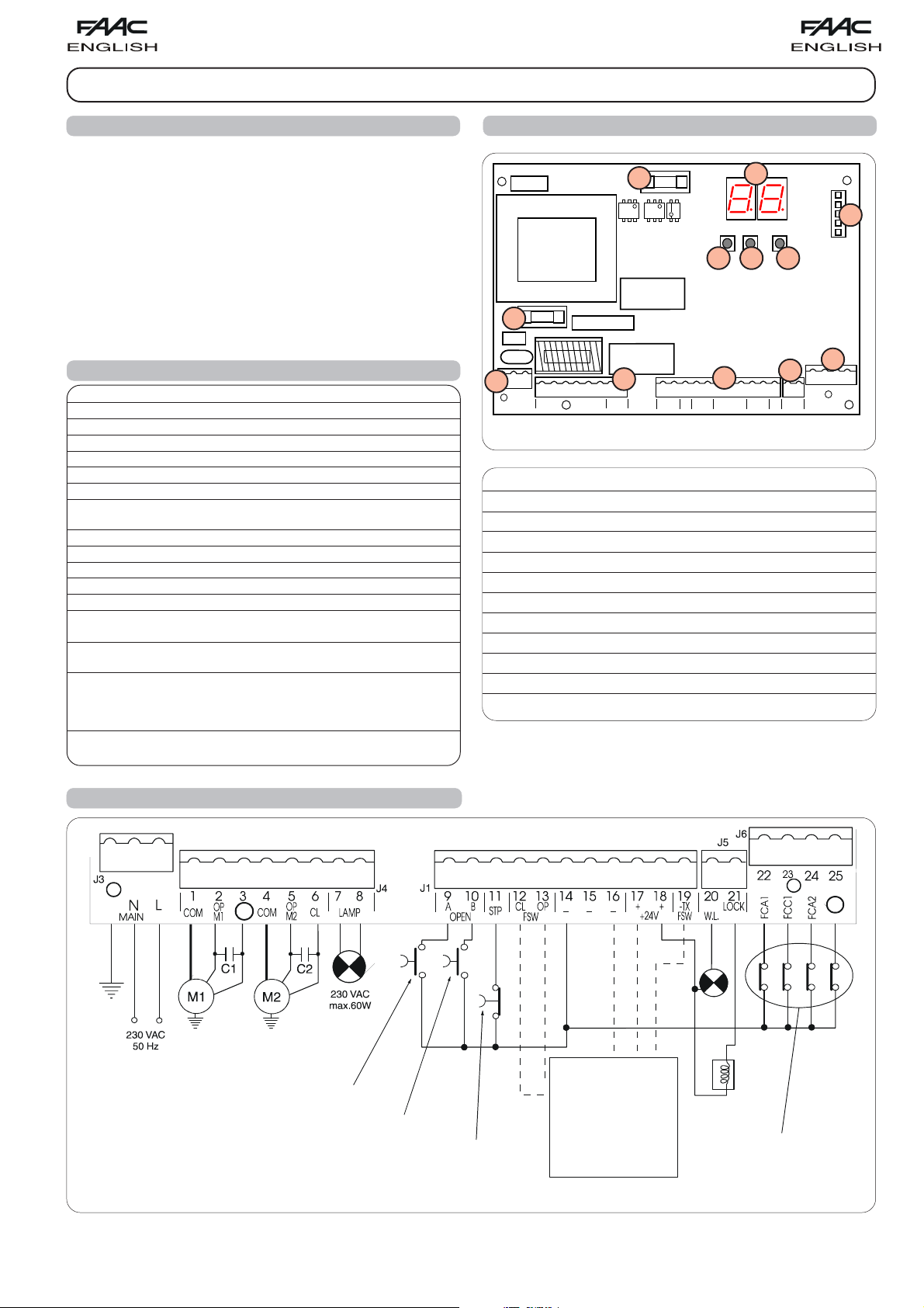
3. LAYOUT AND COMPONENTS OF 455 D
Important: Before attempting any work on the control board
(connections, maintenance), always turn off power.
- Install, upstream of the system, a differential thermal breaker
with adequate tripping threshold.
- Connect the earth cable to the appropriate terminal on the J3
connector of the equipment (see fig.2).
- Always separate power cables from control and safety cables
(push-button, receiver, photocells, etc.). To avoid any electric
noise, use separate sheaths or a shielded cable (with earthed
shield).
F1
2. TECHNICAL SPECIFICATIONS
Power supply 230 V~ ( +6% -10%) - 50 Hz
Absorbed power 10 W
J3
J3
PE N
MAIN
Motor max. load 800 W
Accessories max. load 0,5 A
Electric lock max. load 15 VA
Operating ambient temperature -20 °C +55 °C
Protection fuses 2 (see fig. 1)
Function logics Semi-automatic / Automatic / Safety devices / "Stepped" semi-automatic
/ "Stepped" automatic / "Stepped" Safety devices / Semi-automatic B / Dead-man C
Opening/closing time Programmable (from 0 to 120 s)
Pause time Programmable (from 0 to 4 min.)
Closing leaf delay Programmable (from 0 to 4 min.)
Opening leaf delay 2 s (can be excluded)
Thrust force Adjustable on 50 levels for each motor
Terminal board inputs Open / Open free leaf / Stop / Limit-switch
Opening safety devices / Closing safety devices / Power supply + Earth
Terminal board outputs Flashing lamp - Motors - 24 Vdc accessories power
supply- 24 Vdc indicator-light - Fail safe - 12 Vac electric lock power supply
Programmable functions Logic - Pause time - Thrust Force - Torque at initial thrust
Opening and closing leaf delay - Reversing stroke - Over-pushing stroke - indicatorlight - Pre-flashing - Electric lock - Fail safe - Safety devices logic - Assistance request
DL SIGNALLING AND PROGRAMMING DISPLAY
J1 LOW VOLTAGE TERMINAL BOARD
J2 CONNECTOR FOR DECODER/MINIDEC/RP RECEIVER
J3 230 VAC POWER SUPPLY TERMINAL BOARD
J4 MOTORS AND FLASHING LAMP CONNECTION TERMINAL BOARD
J5 INDICATOR-LIGHT AND ELECTRIC LOCK TERMINAL BOARD
J6 LIMIT-SWITCH AND GATECODER TERMINAL BOARD
F1 MOTORS AND TRANSFORMER PRIMARY WINDING FUSE (F 5A)
F2 LOW VOLTAGE AND ACCESSORIES FUSE (T 800mA)
F "F" PROGRAMMING PUSH-BUTTON
– "–" PROGRAMMING PUSH-BUTTON
+ "+" PROGRAMMING PUSH-BUTTON
- Detection time of obstacle or contact point
Learning function
Simple
or
complete
work time learning, with or without
Limit-switch and/or Gatecoder.
F1
12 45678
L
COM
OP
OP
COM
M2
M1
F2
F2
J4
J1
J4
9 10111213141516171819
AB
CL
CL
LAMP
OPEN
STP
FSW
OP
OP_A
STOP
OP_B
J1
---
FSWCL
+
DL
FCA2
–
–+
++
+24V
FCC1
FCC2
F
J2
J2
F
J6
J6
J5
J5
222324 25
20 21
-TX
LOCK
FCA1
FCC2
FCC1
FSW
W.L.
FCA2
FCA1
FSWOP
Fig. 1
4. ELECTRIC CONNECTIONS
PE
BLUE
NB.: Capacitors are supplied with the operators.
BLUE
TOTALLY OPEN
OPEN LEAF 1
STOP
For connection of
the photocells
and safety
devices, see
paragraph 4.1
(page 14).
24 Vdc
3 W
12 V ac
FCC2
LIMIT-SWITCH
Fig. 2
13
Page 4
1
2
5
4
3
1
2
RX CL TX CL
1
2
5
4
3
1
2
RX OP/CL
TX OP/CL
9 10111213141516171819
OPEN
A
B
STP
CL
OP
FSW
--+24V
++
-TX
FSW
20 21
W.L.
LOCK
-
+
-
+
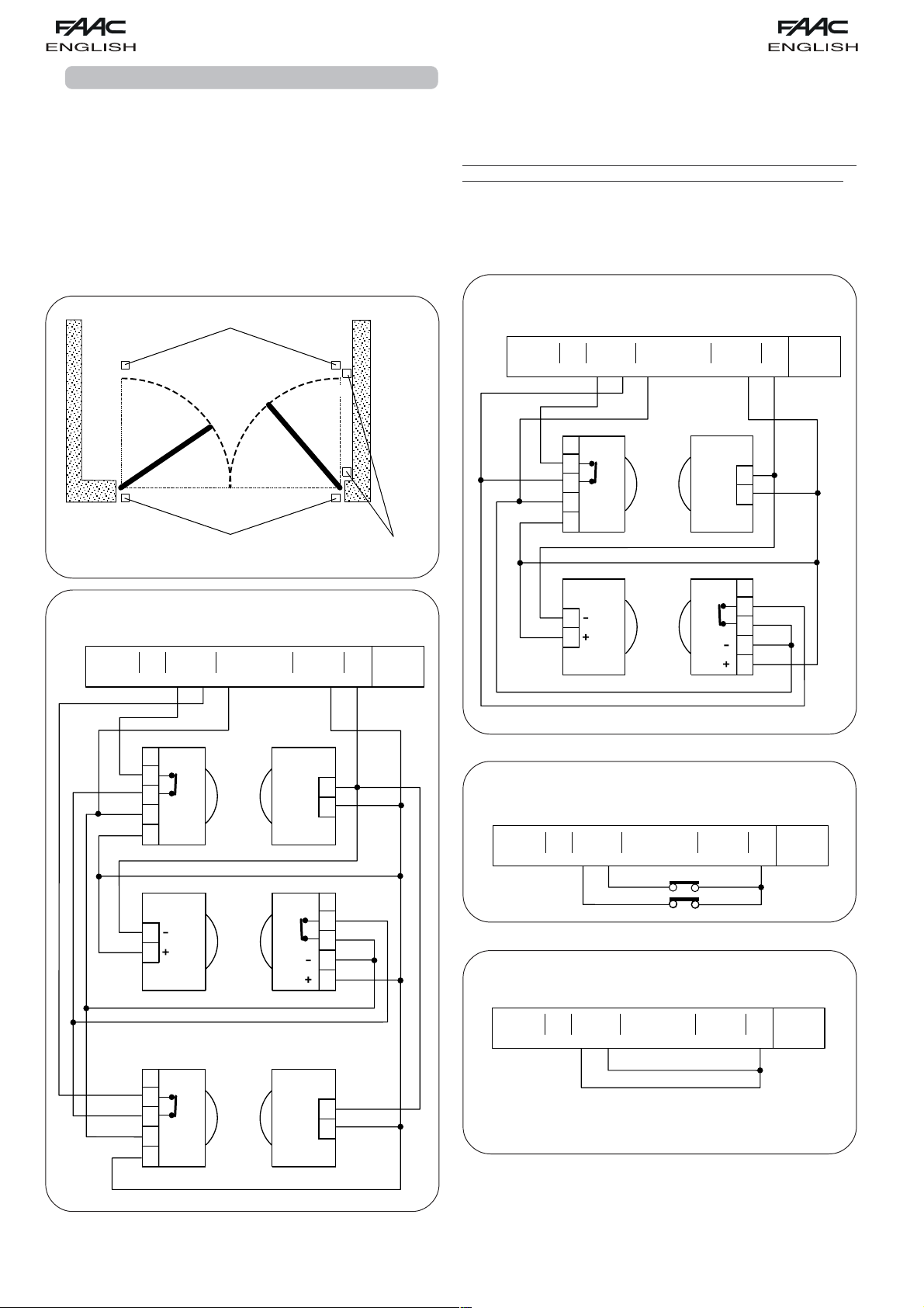
4.1. CONNECTION OF PHOTOCELLS AND SAFETY DEVICES
Before connecting the photocells (or other devices) we advise
you to select the type of operation according to the movement
area they have to protect (see fig.3):
Opening safety devices:
they operate only during the gate
opening movement and, therefore, they are suitable
for protecting the area between the opening leaves
and fixed obstacles (walls, etc) against the risk of
impact and crushing.
Closing safety devices:
they operate only during the gate
closing movement and, therefore, they are suitable
for protecting the closing area against the risk of
impact.
Opening/closing safety devices
Opening/closing safety devices:
they operate during the gate
opening and closing movements and, therefore, they
are suitable for the opening and closing areas against
the risk of impact.
FAAC recommends use of the lay-out in fig. 4 (in the event of
fixed obstacles at opening) or in fig. 5 (no fixed obstacles).
N.B. If two or more devices have the same function (opening
or closing), they should be connected to each other in series
(see fig. 12). N.C. contacts must be used.
Connection of a pair of closing photocells and a pair of
opening/closing photocells (recommended lay-out)
Closing safety devices
Fig. 3
Connection of a pair of closing photocells, a pair of
opening photocells and a pair of opening/closing
photocells (recommended lay-out)
9 10111213141516171819
A
OPEN
B
STP
CL
FSW
OP
---
RX CL TX CL
1
2
3
4
-
+
5
1
2
TX OP/CL
Fig. 4
RX OP TX OP
1
2
3
4
-
+
5
++
+24V
-
+
RX OP/CL
-
+
Opening
safety devices
20 21
-TX
FSW
W.L.
1
2
1
2
3
4
5
1
2
LOCK
14
Fig. 5
Connection of a closing safety device and an opening
9 10111213141516171819
B
A
OPEN
STP
CL
FSW
OP
safety device
---
++
+24V
-TX
FSW
20 21
LOCK
W.L.
Fig. 6
Connection of no safety device
9 10111213141516171819
B
A
OPEN
STP
CL
FSW
OP
---
++
+24V
-TX
FSW
20 21
LOCK
W.L.
Fig. 7
Page 5

1
2
5
4
3
1
2
RX CL1
TX CL1
1
2
5
4
3
1
2
RX CL2
TX CL2
9 10111213141516171819
OPEN
A
B
STP
CL
OP
FSW
--+24V
++
-TX
FSW
20 21
W.L.
LOCK
-
+
-
+
Connection of 1 pair of opening photocells
9 10111213141516171819
B
A
OPEN
STP
CL
FSW
OP
---
++
+24V
-TX
FSW
20 21
LOCK
W.L.
Connection of two pairs of closing photocells
RX
1
2
3
4
-
+
5
TX
Fig. 8
Connection of 1 pair of closing photocells
9 10111213141516171819
B
A
OPEN
STP
CL
FSW
OP
---
RX
1
2
3
4
-
+
5
++
+24V
TX
Fig. 9
1
-
2
+
20 21
LOCK
-TX
FSW
W.L.
Fig. 11
1
-
+
2
Connection of 2 N.C. contacts in series
(e.g. Photocells, Stop)
Connection of a pair of opening photocells and a pair of
closing photocells
9 10111213141516 171819
B
A
OPEN
STP
CL
FSW
OP
---
RX OP
1
2
3
4
-
+
5
TX CL
Fig. 10
1
-
+
2
++
+24V
TX OP
-
+
RX CL
-
+
1
2
4
1
2
3
5
-TX
FSW
20 21
LOCK
W.L.
Fig. 12
Connection of 2 N.O. contacts in parallel
(e.g. Open A, Open B)
Fig. 13
4.2. TERMINAL BOARD J3 - POWER SUPPLY (FIG. 2)
PE: Earth connection
N:230 V~ power supply ( Neutral )
L:230 V~ power supply ( Line )
NB.: For correct operation, the board must be connected to
the earth conductor in the system. Install an adequate
differential thermal breaker upstream of the system.
4.3. TERMINAL BOARD J4 - MOTORS AND FLASHING LAMP
(FIG. 2)
M1 : COM / OP / CL: Connection to Motor 1
Can be used in the single-leaf application
M2 : COM / OP / CL: Connection to Motor 2
Cannot be used in the single-leaf application
LAMP : Flashing lamp output ( 230 V ~)
15
Page 6

MINIDEC
SL / DS / SLH
PLUS
433 / 868
455 D
4.4. TERMINAL BOARD J1 - ACCESSORIES (FIG. 2)
OPEN A - "Total Opening" command (N.O.): any pulse
generator (push-button, detector, etc.) which, by closing
a contact, commands opening and/or closing of both
gate leaves.
To install several full opening pulse generators, connect
the N.O. contacts in parallel.
OPEN B - "Partial Opening" command (N.O.) / Closing: any
pulse generator (push-button, detector, etc.) which,
by closing a contact, commands opening and/or
closing of the leaf driven by motor M1.
In the B and C
logics, it always commands closing of both leaves.
To install several partial opening pulse generators,
connect the N.O. contacts in parallel.
STP - STOP contact (N.C.): any device (e.g. a push-button)
which, by opening a contact, is able to stop gate
movement.
To install several STOP devices, connect the N.C.
contacts in series.
NB.: If STOP devices are not connected, jumper connect
the STP terminals and -.
CL FSW - Closing safety devices contact (N.C.): The purpose
of the closing safety devices is to protect the leaf
movement area during closing. During closing, in the E-
A-S-EP-AP-SP logics, the safety devices reverse the
movement of the gate leaves, or stop and reverse the
movement when they are released (see advanced
programming in Chapter 5.2.). During the closing cycle
in logics B and C, they interrupt movement.
They never
operate during the opening cycle. If the closing safety
devices operate when the gate is open, they prevent
the leaf closing movement.
NB.: If no closing safety devices are connected, jumper
connect terminals CL and -TX FSW (fig. 7).
OP FSW - Opening safety devices contact (N.C.): The purpose
of the opening safety devices is to protect the leaf
movement area during opening. During opening,in the
E-A-S-EP-AP-SP
movement of the gate leaves
in logics B and C, they interrupt movement.
logics,
the safety devices reverse the
. During the opening cycle
They never
operate during the closing cycle.
If the opening safety devices operate when the gate is
closed, they prevent the leaf opening movement.
NB.: If no opening safety devices are connected, jumper
connect inputs OP and -TX FSW (fig. 7).
– - Negative for power supply to accessories
4.6. CONNECTOR J2 - RAPID CONNECTION TO MINIDEC,
DECODER AND RP
This is used for rapid connection of Minidec, Decoder and RP
receivers (see fig. 14, 15, 16 and 17). Connect the accessory,
with the components side facing the inside of the card. Insert
and remove after cutting power.
Fig. 14
PLUS
433 / 868
455 D
DECODER
SL / SLH
Fig. 15
PLUS
DIGIKEY
DIGICARD
433 / 868
N.B.:
accessories (Plus 433 or 868,
Digicard, Digikey) in parallel
Never put two
on the same decoder, but
use a decoder for every
accessory.
+ - 24 Vdc - Positive for power supply to accessories
Important: Accessories max. load is 500 mA. To
calculate absorption values, refer to the instructions
for individual accessories.
-TX FSW - Negative for power supply to photocell
transmitters.
If you use this terminal for connecting the negative for
supplying power to the photocell transmitters, you
may, if necessary, also use the FAIL SAFE function (see
advanced programming in Chapter 5.2.).
If this function is enabled, the equipment checks
operation of the photocells before every opening or
closing cycle.
4.5. TERMINAL BOARD J5 - INDICATOR-LIGHT AND ELECTRIC
LOCK (FIG.2)
W.L. - Power supply to indicator-light
Connect a 24 Vdc - 3 W max. indicator-light, if
necessary, between this terminal and the +24V supply.
To avoid compromising correct operation of the system,
do not exceed the indicated power.
LOCK - Power supply to electric lock
If necessary, connect a 12 V ac electric lock between
this terminal and the +24V supply.
455 D
Fig. 16
RP 433 DS / SL
RP 868 DS / SLH
455 D
Fig. 17
16
Page 7

4.7. TERMINAL BOARD J6 - LIMIT-SWITCHES AND/OR
GATECODER (FIG.2)
These inputs are designed for connection of opening and
closing limit-switches which, according to type of programming
- can command either leaf stop or start of deceleration.
Unconnected limit-switches must be jumper connected (if no
limit-switch is connected, there is no need to make jumpers).
Gatecoders can also be used to detect the leaf's angular
position and to thus obtain deceleration and stop positions
independent of work time.
Limit-switches and Gatecoders can also be used in combination
to stop movement before the mechanical stop limit is reached.
To wire, see fig. 18, 19 and 20.
FCA1 - Leaf 1 opening limit-switch
FCC1 - Leaf 1 closing limit-switch
FCA2 - Leaf 2 opening limit-switch
FCC2 - Leaf 2 closing limit-switch
Fig. 18
14 15 16 17 18 19
---
++
+24V
-TX
FSW
J5
20 21
LOCK
W.L.
J6
23
22
FCA1
24 25
FCC1
FCA2
FCC2
Fig. 19
FCC2
RED
BLACK
RED
BLACK
WHITE
WHITE
Fig. 20
5. PROGRAMMING
To program operation of the automated system, you have to
access the "
Programming is split into two parts:
5.1. BASIC PROGRAMMING
To access BASIC PROGRAMMING, press key F:
•if you press it (and hold it down), the display shows the name
of the first function.
•if you release the key, the display shows the value of the
function that can be modified with keys + and -.
•if you press F again (and hold it down), the display shows the
name of the next function, etc.
•when you reach the last function, press F to exit the program,
and the display resumes showing the status of the inputs.
The following table shows the sequence of functions accessible
in BASIC PROGRAMMING:
BASIC PROGRAMMING
PROGRAMMING
" mode.
BASIC
and
ADVANCED
F
.
!
Display Function Default
FUNCTION LOGICS (see tab. 3/a - h):
= Semi-automatic
= Automatic
= "Safety" Automatic
= "Stepped" Semi-automatic
= "Stepped" Automatic
= "Safety Stepped" Automatic
= "B" Semi-automatic
= Dead-man
PAUSE TIME:
This has effect only if the automatic logic
was selected. Adjustable from
sec. in one-second steps.
Subsequently, display changes to
minutes and tens of seconds (separated
by a point) and time is adjusted in 10second steps, up to the maximum value
of
minutes.
E.g. if the display shows
is 2 min. and 50 sec.
LEAF 1 FORCE :
Adjusts thrust of Motor 1.
= maximum force (hydraulic)
LEAF 2 FORCE :
Adjusts thrust of Motor 2.
= minimum force
= maximum force (hydraulic)
= minimum force
*
*
to
, pause time
FCC2
RED
BLACK
RED
BLACK
N.B.:Maximum configurations are shown on the drawings.
All intermediate configurations are allowed, using only
some elements (only 1 Gatecoder, only 1 limit-switch, 2
Gatecoders and 2 limit-switches etc.).In this case, the
unused inputs must be jumpered to earth
WHITE
WHITE
LEAF 1 CLOSING DELAY:
Delays closing start of leaf 1 with respect to
leaf 2. Adjustable from
(see Pause Time).
TIME LEARNING (see Chapter 6.3.):
Enables the selection between "simple"
(automatic) learning and "complete"
(manual choice of deceleration and stop
points) learning.
Simple learning:
to minutes
+
앓앓
앓
1 s.
앓앓
!
+
>
Complete learning:
3 s.
!
Exit from programming and return to
display of inputs status.
NB.:
*
if you are using hydraulic operators, set force to maximum
level.
17
Page 8

5.2. ADVANCED PROGRAMMING
To access ADVANCED PROGRAMMING, press key F and, as
you hold it down, press key
•if you release key + , the display indicates the name of the first
function.
•if you release key F too, the display shows the value of the
function that can be modified with keys + and -.
•if you press key F (and hold it down), the display shows the
name of the next function, and if you release it, the value
that can be modified with keys + and - is shown.
•when you reach the last function, press F to exit the program,
and the display resumes showing the status of the inputs.
The following table shows the sequence of functions accessible
in ADVANCED PROGRAMMING:
ADVANCED PROGRAMMING
Display Function Default
MAXIMUM TORQUE AT INITIAL THRUST :
The motors operate at maximum torque
(ignoring the torque setting) at start of
movement. Useful for heavy leaves.
= Active = Disabled
LAST STROKE AT CLOSING:
The motors are activated at full speed
for 1 s to facilitate locking of the electric
lock.
= Active = Disabled
REVERSING STROKE:
Before opening, while the gate is closed,
the motors thrust to close for 2 s thus
facilitating release of the electric lock.
= Active = Disabled
+:
F
!
+
+
!
Display Function Default
INDICATOR-LIGHT:
If
is selected, the output functions as a
standard indicator-light (lighted at
opening and pause, flashing at closing,
and off when gate closed). Different
figures correspond to the extra time
compared to normal work time (opening
or closing) when the output can be used
- via a relay - to power a courtesy light.
Time can be adjusted from to s in
1 s steps, and from
10 s steps.
= Standard indicator-light
to = Timed output
from
CLOSING PHOTOCELLS REVERSE AT
RELEASE:
Enable this function if you want the
closing photocells to stop movement
and reverse it at release. Default setting
is immediate reverse.
= Active = Disabled
A.D.M.A.P. function:
If this function is enabled, the safety
devices operate in compliance with
French standard NFP 25/362.
= Active = Disabled
ASSISTANCE REQUEST (combined with
next function):
If activated, at the end of countdown
(settable with the next function i.e. "Cycle
programming") it effects 8 s of preflashing at every Open pulse (job
request). Can be useful for setting
scheduled maintenance jobs.
= Active = Disabled
to min. in
LEAF 2 OPENING DELAY (2 s):
Enables delayed start (at opening) of leaf 2,
avoiding interference between leaves.
= Active = Disabled
FAIL SAFE:
If this function is activated, it enables a
function test of the photocells before
any gate movement. If the test fails
(photocells not serviceable), the gate
does not start the movement.
= Active = Disabled
PRE-FLASHING (5 s):
Activates the flashing lamp for 5 s before
start of movement.
= Active = Disabled
ELECTRIC LOCK ON LEAF 2:
For using the electric lock on leaf 2 instead
of on leaf 1.
= Active = Disabled
NB.:
modification of programming parameters comes into effect immediately, whereas definitive memory storage occurs only when
you exit programming and return to gate status viewing. If the equipment is powered down before return to status viewing, all
modifications will be lost.
To restore the default settings of the programming press the three buttons +, -, F simultaneously and keep them pressed for 5
seconds.
18
CYCLE PROGRAMMING:
For setting countdown of system
operation cycles. Settable (in thousands)
from
displayed value is updated as cycles
proceed.
This function can be used to check use
of the board or to exploit the "Assistance
request".
ANTI-CRUSHING SENSITIVITY:
When operating with the gatecoder, it
controls anti-crushing sensitivity.
EXTRA WORK TIME:
When operating without a gatecoder
and limit-switch, if reversing occurs, and
if the leaf does not reach its end contact
point, you can activate this function to
increase work time.
Exit from programming and return to
display of inputs status.
to thousand cycles.The
= Low = High.
= Active = Disabled
Page 9

6. START-UP
6.1. LED CHECK
The board has a two-digit display. If out of the
"PROGRAMMING" mode, this display is used to indicate status
of inputs. Fig. 16 shows how the segments (we'll call these
LEDs from now on) of the display exactly correspond to the
inputs.
Fig. 21
The table below shows the status of the LEDs in relation to to
the status of the inputs.
Note the following:
LED
LIGHTED
= closed contact
LED
OFF
= open contact
Check the state of the LEDs as per Table.
Operation of the status signalling LEDs
LEDs LIGHTED OFF
OP_A Command activated Comando inattivo
OP_B Command activated Comando inattivo
STOP Command inactive Command activated
FSWCL Safety devices disengaged Safety devices engaged
FSWOP Safety devices disengaged Safety devices engaged
FCA1 (if used) Limit-switch free Limit-switch engaged
FCC1 (if used) Limit-switch free Limit-switch engaged
FCC2 (if used) Limit-switch free Limit-switch engaged
FCA2 (if used) Limit-switch free Limit-switch engaged
NB.:
The status of the LEDs while the gate is closed at rest are shown in bold.
6.2. ROTATION DIRECTION AND FORCE CHECK
1) Program the functions of the 455 D control board according
to need, as shown in Chapter 5.
2) Cut power to the electronic control equipment.
3) Release the operators and manually move the gate to the
mid-point of the opening angle.
4) Re-lock the operators.
5) Restore power.
6) Send and opening command on the OPEN A input (fig.2)
and check if the gate leaves are being commanded to
open.
N.B.: If the first OPEN A pulse commands a closing, cut power
and change over the phases of the electric motor (brown
and black wires) on the 455 D terminal board.
7) Check power setting of the motors and, if necessary,
modify it (see Chapter 5.1).
N.B.:If using hydraulic operators, force should be programmed to
maximum level (50)
8) Stop leaf movement with a STOP command.
9) Release the operators, close the leaves and re-lock the
operators.
6.3. LEARNING OF OPERATING TIMES
WARNING:
during the learning procedure, the safety devices are disabled!
Therefore any transit must be avoided in the leaf movement
area when this operation is carried out.
Make sure the travel limit mechanical stops are present.
Opening/closing time is established by a learning procedure
which varies slightly according to whether you are using limitswitches and/or Gatecoders.
6.3.1. LEARNING OF NORMAL TIMES
Normal learning (i.e. without limit-switches and Gatecoders)
can be done in two different ways:
- SIMPLE LEARNING (without deceleration):
Check if the leaves are closed, enter "
BASIC PROGRAMMING
",
select the TIME LEARNING function and press the + push-button
for 1 second: the display begins flashing and the leaves begin
the opening movement.
As soon as the leaves reach the opening contact point, give
an OPEN A pulse (with the key operated push-button or with
the radio control) to stop the movement: the leaves stop and
the display stops flashing.
Press push-button F to exit and save the programming.
The procedure has ended and the gate is ready to operate.
- COMPLETE LEARNING (with deceleration):
Check if the leaves are closed, enter "
BASIC PROGRAMMING
",
select the TIME LEARNING function and press the + push-button
for more than 3 seconds: the display begins flashing and leaf
1 begins the opening movement. The following functions can
be commanded by the OPEN A pulses (by key push-button or
radio control):
1° OPEN - Deceleration at opening of leaf 1
2° OPEN - Leaf 1 stops at opening and leaf 2 begins its
opening movement
3° OPEN - Deceleration at opening of leaf 2
4° OPEN - Leaf 2 stops at opening and immediately begins
its closing movement
5° OPEN - Deceleration at closing of leaf 2
6° OPEN - Leaf 2 stops at closing and leaf 1 begins its
closing movement
7° OPEN - Deceleration at closing of leaf 1
8° OPEN - Leaf 1 stops at closing
The display stops flashing: press push-button F to exit and save
the programming.
The procedure has finished and the gate is ready to operate.
Notes: •If you wish to eliminate deceleration in certain
stages, wait for the leaf to reach its stop-limit and
supply 2 consecutive Open pulses (by 1 second).
•If only one leaf is present, the entire sequence must
nevertheless be effected. When the leaf has finished
opening, supply 5 Open pulses until the leaf begins
to close, and then resume normal operation.
6.3.2. LEARNING WITH LIMIT-SWITCHES
Learning with limit-switches can be done in two different ways:
- SIMPLE LEARNING (without deceleration):
Check if the leaves are closed, enter "
BASIC PROGRAMMING
",
select the TIME LEARNING function and press the + push-button
for 1 second: the display begins flashing and the leaves begin
the opening movement.
The motors stop automatically when the opening limit-switches
are reached, but an OPEN A pulse must be given (by radio
control or key push-button) to end the cycle.
The display stops flashing: press push-button F to exit and save
the programming.
The procedure has finished and the gate is ready to operate.
- COMPLETE LEARNING (with deceleration):
Check if the leaves are closed, enter "BASIC PROGRAMMING",
select the TIME LEARNING function and press the + push-button
for more than 3 seconds: the display begins flashing and leaf
1 begins the opening movement.
19
Page 10

Le descrizioni e le illustrazioni del presente manuale non sono impegnative. La FAAC si riserva il diritto, lasciando
inalterate le caratteristiche essenziali dell’apparecchiatura, di apportare in qualunque momento e senza
impegnarsi ad aggiornare la presente pubblicazione, le modifiche che essa ritiene convenienti per miglioramenti
tecnici o per qualsiasi altra esigenza di carattere costruttivo o commerciale.
The descriptions and illustrations contained in the present manual are not binding. FAAC reserves the right, whilst
leaving the main features of the equipments unaltered, to undertake any modifications it holds necessary for either
technical or commercial reasons, at any time and without revising the present publication.
Les descriptions et les illustrations du présent manuel sont fournies à titre indicatif. FAAC se réserve le droit
d’apporter à tout moment les modifications qu’elle jugera utiles sur ce produit tout en conservant les caractéristiques
essentielles, sans devoir pour autant mettre à jour cette publication.
Die Beschreibungen und Abbildungen in vorliegendem Handbuch sind unverbindlich. FAAC behält sich das Recht
vor, ohne die wesentlichen Eigenschaften dieses Gerätes zu verändern und ohne Verbindlichkeiten in Bezug auf
die Neufassung der vorliegenden Anleitungen, technisch bzw. konstruktiv/kommerziell bedingte Verbesserungen
vorzunehmen.
voor de natuur
100% kringlooppapier
Las descripciones y las ilustraciones de este manual no comportan compromiso alguno. FAAC se reserva el
derecho, dejando inmutadas las características esenciales de los aparatos, de aportar, en cualquier momento
y sin comprometerse a poner al día la presente publicación, todas las modificaciones que considere oportunas
para el perfeccionamiento técnico o para cualquier otro tipo de exigencia de carácter constructivo o comercial.
De beschrijvingen in deze handleiding zijn niet bindend. FAAC behoudt zich het recht voor op elk willekeurig
moment de veranderingen aan te brengen die het bedrijf nuttig acht met het oog op technische verbeteringen
of alle mogelijke andere productie- of commerciële eisen, waarbij de fundamentele eigenschappen van de
apparaat gehandhaafd blijven, zonder zich daardoor te verplichten deze publicatie bij te werken.
FAAC per la natura
• La presente istruzione è realizzata al 100% in carta riciclata.
• Non disperdete nell'ambiente gli imballaggi dei componenti dell'automazione bensì selezionate
i vari materiali (es. cartone, polistirolo) secondo prescrizioni locali per lo smaltimento rifiuti e le
norme vigenti.
FAAC for the environment
• The present manual is produced in 100% recycled paper
• Respect the environment. Dispose of each type of product packaging material (card, polystyrene)
in accordance with the provisions for waste disposal as specified in the country of installation.
FAAC écologique
• La présente notice a été réalisée 100% avec du papier recyclé.
• Ne pas jeter dans la nature les emballages des composants de l’automatisme, mais sélectionner
les différents matériaux (ex.: carton, polystyrène) selon la législation locale pour l’élimination des
déchets et les normes en vigueur.
FAAC der Umwelt zuliebe
• Vorliegende Anleitungen sind auf 100% Altpapier gedruckt.
• Verpackungsstoffe der Antriebskomponenten (z.B. Pappe, Styropor) nach den einschlägigen
Normen der Abfallwirtschaft sortenrein sammeln.
FAAC por la naturaleza.
• El presente manual de instrucciones se ha realizado, al 100%, en papel reciclado.
• Los materiales utilizados para el embalaje de las distintas partes del sistema automático (cartón,
poliestireno) no deben tirarse al medio ambiente, sino seleccionarse conforme a las prescripciones
locales y las normas vigentes para el desecho de residuos sólidos.
FAAC voor de natuur
• Deze gebruiksaanwijzing is gedrukt op 100% kringlooppapier.
• Laat de verpakkingen van de componenten van het automatische systeem niet in het milieu
achter, maar scheidt de verschillende materialen (b.v. karton, polystyreen) volgens de plaatselijke
voorschriften op de afvalverwerkingen en de geldende normen.
para la naturaleza
100% papel reciclado
ist umweltfreundlich
100% Altpapier
pour la nature
papier recyclé 100%
FAAC S.p.A.
Via Benini, 1
40069 Zola Predosa (BO) - ITALIA
Tel.: 051/61724 - Fax: 051/758518
www.faacgroup.com
Timbro del Rivenditore:/Distributor’s Stamp:/Timbre de l’Agent:/ Fachhändlerstempel:/Sello del Revendedor:/Stempel van de dealer:
for nature
recycled paper 100%
per la natura
carta riciclata 100%
732452 - Rev. B
Page 11

The leaves automatically decelerate when they reach the limitswitches, and therefore, it is sufficient to inform the equipment
that the stop limits have been reached by means of OPEN A
pulses (by radio control or key push-button):
FCA1 - Deceleration at opening of leaf 1
1° OPEN - Leaf 1 stops at opening and leaf 2 begins its
opening movement
FCA2 - Deceleration at opening of leaf 2
2° OPEN - Leaf 2 stops at opening and immediately begins
its closing movement
FCC2 - Deceleration at closing of leaf 2
3° OPEN - Leaf 2 stops at closing and leaf 1 begins its
closing movement
FCC1 - Deceleration at closing of leaf 1
4° OPEN - Leaf 1 stops at closing
The display stops flashing: press push-button F to exit and save
the programming.
The procedure has finished and the gate is ready to operate
Notes: •If you wish to eliminate deceleration in some stages,
you must supply an Open pulse within 1 second of
reaching the limit-switch.
•If some limit-switches are not installed, start the
corresponding deceleration by supplying an Open
pulse (which replaces the limit-switch).
•If only one leaf is present, the entire sequence must
nevertheless be effected. When the leaf has finished
opening, supply 5 Open pulses until the leaf begins
to close, and then resume normal operation.
6.3.3. LEARNING TIMES WITH GATECODER
Learning with the Gatecoder can be done in two different
ways:
- SIMPLE LEARNING (with deceleration):
Check if the leaves are closed, enter "
select the TIME LEARNING function and press the + push-button
for 1 second: the display begins flashing and the leaves begin
the opening movement.
The movement stops automatically when the opening stop
limit is reached and the display stops flashing.
Press push-button F to exit and save the programming.
The procedure has ended and the gate is ready to operate,
using fixed deceleration.
BASIC PROGRAMMING
",
- COMPLETE LEARNING (with deceleration):
Check if the leaves are closed, enter "
select the TIME LEARNING function and press the + push-button
for more than 3 seconds: the display begins flashing and leaf
1 begins the opening movement. The following functions can
be commanded by the OPEN A pulses (by radio control or
key push-button):
1° OPEN - Leaf 1 Decelerates at opening (it stops
automatically on reaching the stop limit)
2° OPEN - Leaf 2 opening movement begins
3° OPEN - Leaf 2 Decelerates at opening (it stops
automatically on reaching the stop limit)
4° OPEN - Leaf 2 closing movement begins
5° OPEN - Leaf 2 decelerates at closing (it stops
automatically on reaching the stop limit)
6° OPEN - Leaf 1 closing movement begins
7° OPEN - Leaf 1 Decelerates at closing (it stops
automatically on reaching the stop limit)
8° OPEN- End of learning
The display stops flashing: press push-button F to exit and save
the programming.
The procedure has finished and the gate is ready to operate.
BASIC PROGRAMMING
",
Notes: •The deceleration pulse should be supplied a little
earlier with respect to the stop limit to prevent the
leaf reaching it at full speed (it would be taken for
an obstacle).
•If only one leaf is present, the entire sequence must
nevertheless be effected. When the leaf has finished
opening, supply 5 Open pulses until the leaf begins
to close, and then resume normal operation.
6.3.4. LEARNING TIMES WITH GATECODER + LIMIT-SWITCH
Learning with Gatecoder + Limit-switch can be done in two
different ways:
- SIMPLE LEARNING (without deceleration):
Check if the leaves are closed, and then access
PROGRAMMING”
push-button + for 1 second: the display starts to flash and the
leaves begin the opening movement.
The motors stop automatically when the opening limit-switches
are reached, and the display stops flashing. Press push-button
F to exit and save the programming.
The procedure has finished and the gate is ready to operate.
The Gatecoder is used solely as an obstacle sensor.
, select the TIME LEARNING function and press
“BASIC
- COMPLETE LEARNING (with deceleration):
Check if the leaves are closed, and then access
PROGRAMMING”
push-button + for more than 3 seconds: the display starts to
flash and the leaf 1 begins the opening movement. The leaves
automatically slow down on reaching the limit-switches, and
you can command the following functions with the OPEN A
pulses (from a radio control or from a key operated pushbutton):
FCA1 - Deceleration at opening of leaf 1 (stops
1st OPEN- Opening movement of leaf 2 begins
FCA2 - Deceleration at opening of leaf 2 (stops
2nd OPEN- Closing movement of leaf 2 begins
FCC2 - Deceleration at closing of leaf 2 (stops
3rd OPEN-Closing movement of leaf 1 begins
FCC1 - Deceleration at closing of leaf 1 (stops
4th OPEN- End of learning
The display stops flashing: press push-button F to exit and save
the programming.
The procedure has finished and the gate is ready for normal
operation.
, select the TIME LEARNING function and press
automatically when it reaches the end contact
point)
automatically when it reaches the end contact
point)
automatically when it reaches the end contact
point)
automatically when it reaches the end contact
point)
“BASIC
Note: •If some limit-switches are not installed, start the
corresponding deceleration by supplying an Open
pulse (which replaces the limit-switch).
•If only one leaf is present, the entire sequence must
nevertheless be effected. When the leaf has finished
opening, supply 5 Open pulses until the leaf begins
to close, and then resume normal operation.
7. AUTOMATED SYSTEM TEST
When you have finished programming, check if the system is
operating correctly.
Most important of all, check if the force is adequately adjusted
and if the safety devices are operating correctly.
20
Page 12

)2("2rofnepootsesreveR
)2("2rofesolcotsesreveR
)delbasidNEPO(
)delbasidNEPO(
tceffeoN
tceffeoN
otsesrever,esaelerno,dnaskcoL
nepo
)delbasidNEPO(
tceffeoN
seunitnoc,esaelerno,dnaskcoL
gninepo
)delbasidNEPO(
tceffeoN
)2("2rofnepootsesreveR
)1(emitesuapsdaoleR
)1(emitesuapsdaoleR
)2("2rofesolcotsesreveR
)delbasidNEPO(
)delbasidNEPO(
tceffeoN
seunitnoc,esaelerno,dnaskcoL
otsesrever,esaelerno,dnaskcoL
)delbasidNEPO(
gninepo
nepo
)delbasidNEPO(
tceffeoN
)2("2rofnepootsesreveR
)1(emitesuapsdaoleR
"5retfasesolc,esaelernO
)2("2rofesolcotsesreveR
)delbasidNEPO(
)delbasidNEPO
tceffeoN
seunitnoc,esaelerno,dnaskcoL
otsesrever,esaelerno,dnaskcoL
)delbasidNEPO(
gninepo
nepo
)2("2rofnepootsesreveR
)2("2rofesolcotsesreveR
)delbasidNEPO(tceffeoN
seunitnoc,esaelerno,dnaskcoL
otsesrever,esaelerno,dnaskcoL
gninepo
nepo
)3()1(emitesuapsdaoleR
.2.5hpargarapees
)delbasidNEPO(
)3(tceffeoN
tceffeoN
tceffeoN
)delbasidANEPO.gnpo.trapnofi(
)NEPOsevas(
tceffeoN
tceffeoN
)delbasidNEPO(
tceffeoN
)delbasidNEPO(
tceffeoN
noitarepo
spotS
,degagnesecivedytefaSgnisolChtiw(faelehtsesolC
)3(yletaidemmifaelehtsesolc-eR
yletaidemmifaelehtsnepo-eR
)3()eslupdn2ehttasnepo
)3(noitarepospotS esolcotsesreveRtceffeoN
tceffeoN
)delbasidNEPO(
tceffeoN
sesolcdnafaelelgnissnepO
)1(emitesuapretfa
.2.5hpargarapees
tceffeoN
)delbasidANEPO.gnpo.trapnofi(
)NEPOsevas(
tceffeoN
tceffeoN
)delbasidNEPO(
tceffeoN
noitarepo
spotS
)1(yletaidemmifaelehtsnepo-eR
)3()1(emitesuapsdaoleR
)3(faelehtsesolC
)3()1(tceffeoN esolcotsesreveRtceffeoN
NEPO("5retfasesolc,esaelernO
.2.5hpargarapees
)3()delbasid
tceffeoN
)delbasidANEPO.gnpo.trapnofi(
tceffeoN
)delbasidNEPO(
tceffeoN
sesolcdnafaelelgnissnepO
emitesuapretfa
)3(yletaidemmifaelehtsesolc-eR
)NEPOsevas(
tceffeoN
tceffeoN
)NEPOsevas(
tceffeoN
)delbasidNEPO(
tceffeoN
noitarepo
spotS
)3(yletaidemmifaelehtsesolc-eR esolcotsesreveR
yletaidemmifaelehtsnepo-eR
)3(faelehtsesolC
)3()delbasidNEPO(tceffeoN )delbasidNEPO(tceffeoN
tceffeoN )delbasidNEPO(tceffeoN
ANEPO.gnpo.trapnofi(tceffeoN
)delbasid
)delbasidNEPO(
tceffeoN
noitarepo
spotS
)3(yletaidemmifaelehtsesolc-eR
noitarepospotS )NEPOsevas(tceffeoN.2.5hpargarapees
)NEPOselbasidti,esolctsumtifi(
tceffeoN
)NEPOselbasidti,nepotsumtifi(
tceffeoN
)delbasidNEPO(
tceffeoN
)3(noitceridesrevernitnemevomstratseR
)potSaretfasesolcsyawla(
)3(noitarepospotS esolcotsesreveRtceffeoN
SUTATSETAGA-NEPOB-NEPOPOTSSECIVEDYTEFASGNINEPOSECIVEDYTEFASGNISOLCECIVEDYTEFASLC/POECIVEDYTEFASEGDE
"E"cigoL SESLUP
Tab. 3/a
sesolcdnafaelehtsnepO
)1(emitesuapretfati
faelehtsnepOfaelelgnissnepO
SUTATSETAGA-NEPOB-NEPOPOTSSECIVEDYTEFASGNINEPOSECIVEDYTEFASGNISOLCECIVEDYTEFASLC/POECIVEDYTEFASEGDE
GNINEPO
DESOLC
GNISOLC
NEPO
DEKCOL
"A"cigoL SESLUP
Tab. 3/b
ESUAPnoNEPO
GNINEPO
DESOLC
GNISOLC
DEKCOL
Tab. 3/c
sesolcdnafaelehtsnepO
emitesuapretfati
SUTATSETAGA-NEPOB-NEPOPOTSSECIVEDYTEFASGNINEPOSECIVEDYTEFASGNISOLCECIVEDYTEFASLC/POECIVEDYTEFASEGDE
"S"cigoL SESLUP
ESUAPnoNEPO
GNINEPO
DESOLC
GNISOLC
DEKCOL
faelehtsnepOfaelelgnissnepO
SUTATSETAGA-NEPOB-NEPOPOTSSECIVEDYTEFASGNINEPOSECIVEDYTEFASGNISOLCECIVEDYTEFASLC/POECIVEDYTEFASEGDE
"PE"cigoL SESLUP
DESOLC
NEPO
GNINEPO
GNISOLC
DEKCOL
Tab. 3/d
21
Page 13

)2("2rofnepootsesreveR
)2("2rofesolcotsesreveR
emitesuapsdaoleR
)delbasidNEPO(
)2("2rofnepootsesreveR
)1(emitesuapsdaoleR
)2("2rofesolcotsesreveR
)delbasidNEPO(
)2("2rofnepootsesreveR
)delbasidB/A-NEPO(
tceffeoN
)2("2rofnepootsesreveR
)delbasidB/A-NEPO(
tceffeoN
)delbasidNEPO(
tceffeoN
otsesrever,esaelerno,dnaskcoL
emitesuapsdaoleR
)delbasidNEPO(
nepo
)3(emitesuapsdaoleR
.2.5hpargarapees
)delbasidNEPO(
tceffeoN
)delbasidANEPO.gnpo.trapnofi(
)NEPOsevas(
tceffeoN
tceffeoN
)delbasidNEPO(
tceffeoN
)delbasidNEPO(
tceffeoN
seunitnoc,esaelerno,dnaskcoL
gninepo
tceffeoN
)delbasidNEPO(
tceffeoN
otsesrever,esaelerno,dnaskcoL
"5retfasesolc,esaelernO
)delbasidNEPO(
nepo
NEPO("5retfasesolc,esaelernO
.2.5hpargarapees
)3()delbasid
tceffeoN
)delbasidANEPO.gnpo.trapnofi(
)NEPOsevas(
tceffeoN
tceffeoN
)delbasidNEPO(
tceffeoN
)delbasidNEPO
tceffeoN
seunitnoc,esaelerno,dnaskcoL
gninepo
)NEPOsevas(
tceffeoN
tceffeoN
)delbasidANEPO(
tceffeoN
)delbasidBNEPO(
tceffeoN
)delbasidB-NEPO(
)delbasidBNEPO(
noitarepospotS
tceffeoN
tceffeoN
)ANEPOsevas(
tceffeoN
tceffeoN
)delbasidANEPO(
tceffeoN
)delbasidB/ANEPO(
tceffeoN
)delbasidB/A-NEPO(
noitarepospotS
)delbasidBNEPO(
tceffeoN
tceffeoN )2("2rofesolcotsesreveR
)delbasidA-NEPO(
)delbasidA-NEPO(
noitarepospotS
tceffeoN
)delbasidANEPO(
tceffeoN
)delbasidB/A-NEPO(
)delbasidBNEPO(
noitarepospotS
tceffeoN
)delbasidBNEPO(
)delbasidB-NEPO(
noitarepospotS
tceffeoN
tceffeoN
tceffeoN
)delbasidANEPO(
tceffeoN
tceffeoN )2("2rofesolcotsesreveR
)delbasidANEPO(
)delbasidA-NEPO(
noitarepospotS
tceffeoN
)delbasidNEPO(
tceffeoN
noitarepo
spotS
sesolcdnafaelelgnissnepO
emitesuapretfa
yletaidemmifaelehtsnepo-eR
)3(noitarepospotS
sesolcdnafaelehtsnepO
emitesuapretfati
SUTATSETAGA-NEPOB-NEPOPOTSSECIVEDYTEFASGNINEPOSECIVEDYTEFASGNISOLCECIVEDYTEFASLC/POECIVEDYTEFASEGDE
"PA"cigoL SESLUP
ESUAPnoNEPO
DESOLC
,degagnesecivedytefaSgnisolChtiw(faelehtsesolC
)3()eslupdn2ehttasnepo
)3(noitarepospotS esolcotsesreveRtceffeoN
GNINEPO
GNISOLC
DEKCOL
sesolcdnafaelelgnissnepO
emitesuapretfa
sesolcdnafaelehtsnepO
emitesuapretfati
SUTATSETAGA-NEPOB-NEPOPOTSSECIVEDYTEFASGNINEPOSECIVEDYTEFASGNISOLCECIVEDYTEFASLC/POECIVEDYTEFASEGDE
"PS"cigoL SESLUP
DESOLC
noitarepo
spotS
yletaidemmifaelehtsnepo-eR
)3(noitarepospotS
ESUAPnoNEPO
GNISOLC
)delbasidNEPO(
tceffeoN
)3(noitarepospotS esolcotsesreveR
)3(faelehtsesolC
GNINEPO
DEKCOL
"B"cigoL SESLUP
NEPO(tceffeoN
)delbasidB
faelehtsnepOtceffeoN
SUTATSETAG)gninepo(A-NEPO)gnisolc(B-NEPOPOTSSECIVEDYTEFASGNINEPOSECIVEDYTEFASGNISOLCECIVEDYTEFASLC/POECIVEDYTEFASEGDE
DESOLC
nepootsesreveRtceffeoN
tceffeoNfaelehtsesolC
GNISOLC
NEPO
)delbasidB/ANEPO(
tceffeoN
noitarepo
spotS
faelehtsnepOfaelehtsesolC
tceffeoNtceffeoN
SUTATSETAG)gninepo(A-NEPO)gnisolc(B-NEPOPOTSSECIVEDYTEFASGNINEPOSECIVEDYTEFASGNISOLCECIVEDYTEFASLC/POECIVEDYTEFASEGDE
GNINEPO
DEKCOL
"C"cigoLNWODDLEHSYAWLASLORTNOC SESLUP
)delbasidB/A-NEPO(
noitarepospotS
tceffeoN
)delbasidA-NEPO(
faelehtsesolC
tceffeoN
)delbasidB-NEPO(
faelehtsnepO
DESOLC
noitarepospotS/
tceffeoN
/noitarepospotS
GNINEPO
GNISOLC
NEPO
Tab. 3/e
Tab. 3/f
22
Tab. 3/g
Tab. 3/h
(1) If maintained, it prolongs the pause until disabled by the command (timer function) (3) During the partial opening cycle, an OPEN A pulse causes total opening.
(2) If a new pulse occurs within 2 seconds after reversing, it immediately stops operation. NB.: Effects on other active pulse inputs in brackets.
 Loading...