

Page 1
ENGLISH
CE DECLARATION OF CONFORMITY
Manufacturer: FAAC S.p.A.
Address: Via Benini, 1 - 40069 Zola Predosa BOLOGNA - ITALY
Declares that: 452 MPS control board,
• conforms to the essential safety requirements of the following directives:
73/23/CEE and subsequent amendment 93/68/CEE.
89/336/CEE and subsequent amendment 92/31/CEE and 93/68/CEE
Additional note:
This product underwent tests in a typical uniform configuration
(all products manufactured by FAAC S.p.A.).
Bologna, 01 January 2001
The Managing Director
A. Bassi
INSTALLATION WARNINGS
GENERAL SAFETY OBLIGATIONS
1) CAUTION! It is important for personal safety to follow all the instructions
carefully. Incorrect installation or misuse of the product may cause
people serious harm.
2) Read the instructions carefully before starting to install the product.
3) Packaging material (plastic, polystyrene, etc.) must not be left within reach
of children as it is a potential source of danger.
4) Keep the instructions in a safe place for future reference.
5) This product was designed and manufactured strictly for the use indicated
in this documentation. Any other not expressly indicated use may damage
the product and/or be a source of danger.
6) FAAC accepts no responsibility due to improper use of the automated
system or use other than that intended.
7) Do not install the equipment in an area subject to explosion hazard:
inflammable gases or fumes are a serious safety hazard.
8) Mechanical construction elements must meet the provisions of UNI8612,
EN 12604 and EN 12605 Standards.
To obtain an adequate level of safety in non EU countries, the above
mentioned Standards must be observed in addition to national Standards.
9) FAAC will not accept responsibility if the principles of Good Workmanship
are disregarded in constructing the closing elements to be motorised, and
if any deformation occurs during use of the said elements.
10) Installation must meet the following Standards: UNI8612, EN 12453 and EN
12445.
11) Before carrying out any work on the system, switch off the power supply.
12) The mains power supply of the automated system must be fitted with a allpole switch with contact opening distance of 3mm or greater. Use of a 6A
thermal breaker with all-pole circuit break is recommended.
13) Make sure there is a differential switch with 0.03A threshold upstream of the
system.
14) Check that the earthing system is correctly made and connect the closure
metal parts to it. Also connect the Yellow/Green wire of the automated
system to the earthing system.
15) The automated system includes an intrinsic anti-crushing device consisting
of a torque control which, however, must be installed together with other
safety devices.
16) The safety devices (EN 12978 Standard) protect any dangerous areas
against Mechanical movement risks, such as crushing, dragging, and
shearing.
17) Use of at least one indicator-light (e.g. FAAC LAMP MINILAMP, etc.) is
recommended for every system, as well as a warning sign adequately
fixed to the frame structure, in addition to the devices mentioned at point
"16".
18) FAAC accepts no responsibility regarding safety and correct operation
of the automated system, should components made by manufacturers
other than FAAC be used in the system.
19) Use only FAAC original spare parts for maintenance.
20) Do not make any alterations to the components of the automated system.
21) The installer must supply full information regarding manual operation of
the system in case of an emergency and hand to the user of the system the
“User’s Guide” included with the product.
22) Do not allow children or other persons to stand near the product while in
operation.
23) Keep remote controls or any other pulse generator well away from
children, to prevent the automated system from being activated
accidentally.
24) The user must refrain from attempting to repair or adjust the system
personally and should contact qualified personnel only.
25) Anything not expressly provided for in these instructions is not permitted.
10
Page 2
CONTROL BOARD 452 MPS
ENGLISH
1. WARNINGS
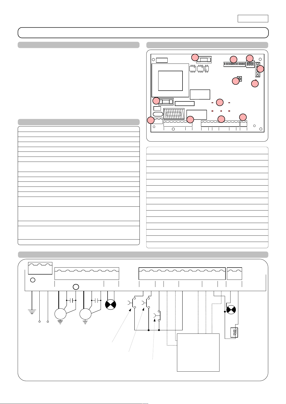
3. LAYOUT AND COMPONENTS OF 452 MPS
Important: Before attempting any work on the control board
(connections, maintenance), always turn off power.
- Install, upstream of the system, a differential thermal breaker
with adequate tripping threshold.
- Connect the earth cable to the appropriate terminal on the J3
connector of the equipment (see fig.2).
- Always separate power cables from control and safety cables
(push-button, receiver, photocells, etc.). To avoid any electric
noise, use separate sheaths or a shielded cable (with earthed
shield).
2. TECHNICAL SPECIFICATIONS
J3
J3
Power supply 230 V~ ( +6% -10%) - 50 Hz
Absorbed power 10 W
Motor max. load 800 W
Accessories max. load 0,5 A
Electric lock max. load 15 VA
Operating ambient temperature -20 °C +55 °C
Protection fuses 2 (see fig. 1)
Function logics Automatic / Semi-automatic / Safety devices /
Semi-automatic B / Dead-man C / "Stepped" semi-automatic
Opening/closing time Programmable (from 0 to 120 s)
Pause time 0, 10, 20, 30, 60, 120 s
Closing leaf delay
0, 5, 10, 20 s
Opening leaf delay 2 s (Can be disabled with the dip-switch)
Thrust force Dip-switch adjustable on 8 levels for each motor
Terminal board inputs Open / Open free leaf / Stop /
Opening safety devices / Closing safety devices / Power supply + Earth
Terminal board outputs Flashing lamp - Motors - 24 Vdc accessories
power supply - 24 Vdc indicator-light - Fail safe 12 Vac electric lock power supply
Rapid connector To connect Minidec, Decoder or RP cards
Selectable functions Logics and pause times - Thrust force -
Opening and closing leaf delay - Reversing stroke -
Fail safe - Closing safety devices logic - Pre-flashing
Programming key work time learning
Led OP_A TOTALLY OPEN LED
Led OP_B LED: OPEN LEAF 1 / CLOSE
Led STOP LED STOP
Led FSWCL LED: CLOSING SAFETY DEVICES
Led FSWOP LED: OPENING SAFETY DEVICES
DL10 LED: TIME LEARNING SIGNALLING
J1 LOW VOLTAGE TERMINAL BOARD
J2 CONNECTOR FOR DECODER/MINIDEC/RP RECEIVER
J3 230 VAC POWER SUPPLY TERMINAL BOARD
J4 MOTORS AND FLASHING LAMP CONNECTION TERMINAL BOARD
J5 INDICATOR-LIGHT AND ELECTRIC LOCK TERMINAL BOARD
F1 MOTORS AND TRANSFORMER PRIMARY WINDING FUSE (F 5A)
F2 LOW VOLTAGE AND ACCESSORIES FUSE (T 800mA)
F TIME LEARNING PUSH-BUTTON
DS1 1ST GROUP OF MICROSWITCH PROGRAMMING
DS2 2ND GROUP OF MICROSWITCH PROGRAMMING
PE N
F1
L
MAIN
F1
J4
12 45678
OP
OP
CL
LAMP
COM
COM
M2
M1
F2
J4
F2
OP_A OP_B
STOP FSWOPFSWCL
J1
9 10111213141516171819
B
CL OP
A
STP
FSW
OPEN
Led
J1
---
DS1
F
++
-TX
+24V
FSW
DS2
910111256781234
1234
J2
J2
F
DL10
DL10
J5
J5
20 21
LOCK
W.L.
Fig. 1
4. ELECTRIC CONNECTIONS
J3
12 45678
MAIN
L
COM
BLUE
PE N
M1
230 VAC
50 Hz
NB.: Capacitors are supplied with the operators.
OP
M1
C1
3
COM
BLUE
M2
OP
M2
C2
CL
230 VAC
max.60W
TOTALLY OPEN
LAMP
OPEN LEAF 1
J5
J4
J1
9 10111213141516171819
B
A
OPEN
STP
CL
FSW
OP
---
++
For connection of
the photocells
+24V
-TX
FSW
20 21
W.L.
24 Vdc
3 W
12 V ac
LOCK
and safety
devices, see
paragraph 4.1
STOP
(page 12).
Fig. 2
11
Page 3
ENGLISH
1
2
5
4
3
1
2
RX CL TX CL
1
2
5
4
3
1
2
RX OP/CL
TX OP/CL
9 10111213141516171819
OPEN
A
B
STP
CL
OP
FSW
--+24V
++
-TX
FSW
20 21
W.L.
LOCK
+
+
9 10111213141516171819
OPEN
A
B
STP
CL
OP
FSW
--+24V
++
-TX
FSW
20 21
W.L.
LOCK
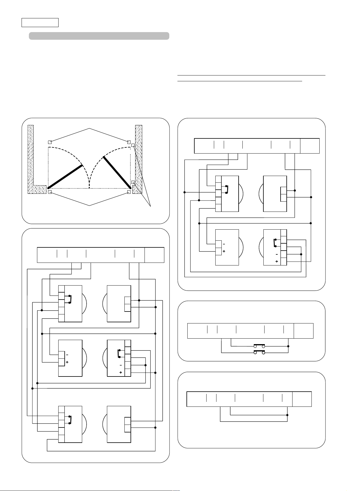
4.1. Connection of photocells and safety devices
Before connecting the photocells (or other devices) we advise
you to select the type of operation according to the movement
area they have to protect (see fig.3):
Opening safety devices:
opening movement and, therefore, they are suitable for
protecting the area between the opening leaves and
fixed obstacles (walls, etc) against the risk of impact
and crushing.
Closing safety devices:
movement and, therefore, they are suitable for
protecting the closing area against the risk of impact.
they operate only during the gate
they operate only during the gate closing
Opening/closing safety devices:
they operate during the gate
opening and closing movements and, therefore, they
are suitable for the opening and closing areas against
the risk of impact.
FAAC recommends use of the lay-out in fig. 4 (in the event of fixed
obstacles at opening) or in fig. 5 (no fixed obstacles).
N.B. If two or more devices have the same function (opening or
closing), they should be connected to each other in series (see
fig. 12). N.C. contacts must be used.
Opening/closing safety devices
Closing safety devices
Fig. 3
safety devices
Connection of a pair of closing photocells, a pair of
opening photocells and a pair of opening/closing
photocells (recommended lay-out)
9 10111213141516171819
A
OPEN
B
STP
CL
FSW
OP
---
++
+24V
-TX
FSW
RX CL TX CL
1
2
3
4
+
5
1
+
2
Opening
20 21
LOCK
W.L.
Connection of a pair of closing photocells and a pair of
opening/closing photocells (recommended lay-out)
Fig. 5
Connection of a closing safety device and an opening
safety device
Fig. 4
1
2
TX OP/CL
RX OP TX OP
1
2
3
4
+
5
RX OP/CL
+
1
2
3
4
5
1
2
12
Connection of no safety device
9 10111213141516171819
B
A
OPEN
STP
CL
FSW
OP
---
++
+24V
-TX
FSW
20 21
LOCK
W.L.
Fig. 6
Fig. 7
Page 4

ENGLISH
Connection of 1 pair of opening photocells
9 10111213141516171819
B
A
STP
OPEN
CL
FSW
OP
---
++
RX
1
2
3
4
+
5
Fig. 8
Connection of 1 pair of closing photocells
9 10111213141516171819
B
A
STP
OPEN
CL
FSW
OP
---
RX
1
2
3
4
+
5
++
+24V
TX
+24V
TX
Connection of two pairs of closing photocells
20 21
LOCK
-TX
FSW
W.L.
1
-
2
+
20 21
W.L.
LOCK
-TX
FSW
9 10111213141516171819
B
A
OPEN
STP
CL
FSW
OP
---
RX CL1
1
2
3
4
+
5
TX CL2
1
2
++
+24V
TX CL1
1
-
+
2
RX CL2
4
1
2
3
5
-TX
FSW
20 21
LOCK
W.L.
Fig. 11
1
-
+
2
Connection of 2 N.C. contacts in series
(e.g. Photocells, Stop)
Fig. 9
Connection of a pair of opening photocells and a pair of
9 10111213141516171819
B
A
OPEN
closing photocells
OP
CL
STP
FSW
RX OP
1
2
3
4
+
5
TX CL
1
+
2
---
++
+24V
TX OP
+
RX CL
+
20 21
LOCK
-TX
FSW
W.L.
1
2
1
2
3
4
5
Fig. 10
Fig. 12
Connection of 2 N.O. contacts in parallel
(e.g. Open A, Open B)
Fig. 13
4.2. Terminal board J3 - Power supply (fig. 2)
PE: Earth connection
N:230 V~ power supply ( Neutral )
L:230 V~ power supply ( Line )
NB.: For correct operation, the board must be connected to the
earth conductor in the system. Install an adequate differential
thermal breaker upstream of the system.
4.3. Terminal board J4 - Motors and flashing lamp (fig. 2)
M1 : COM / OP / CL: Connection to Motor 1
Can be used in the single-leaf application
M2 : COM / OP / CL: Connection to Motor 2
Cannot be used in the single-leaf application
LAMP : Flashing lamp output ( 230 V ~)
13
Page 5

ENGLISH
PLUS
433 / 868
DECODER
SL / SLH
452 MPS
4.4. Terminal board J1 - Accessories (fig. 2)
OPEN A - "Total Opening" command (N.O.): any pulse generator
(push-button, detector, etc.) which, by closing a contact,
commands opening and/or closing of both gate leaves.
To install several full opening pulse generators, connect
the N.O. contacts in parallel (see fig. 13).
OPEN B - "Partial Opening" command (N.O.) / Closing: any
pulse generator (push-button, detector, etc.) which, by
closing a contact, commands opening and/or closing
of the leaf driven by motor M1.
In the B and C logics, it
always commands closing of both leaves.
To install several partial opening pulse generators,
connect the N.O. contacts in parallel (see fig. 13).
STP - STOP contact (N.C.): any device (e.g. a push-button)
which, by opening a contact, is able to stop gate
movement.
To install several STOP devices, connect the N.C. contacts
in series (see fig. 12).
NB.: If STOP devices are not connected, jumper connect
the STP terminals and -.
CL FSW - Closing safety devices contact (N.C.): The purpose
of the closing safety devices is to protect the leaf movement
area during closing. During closing, in the A-S-E-EP logics,
the safety devices reverse the movement of the gate
leaves, or stop and reverse the movement when they are
released (see programming of microswitch DS2 - SW2).
During the closing cycle in logics B and C, they interrupt
movement.
They never operate during the opening
cycle. If the closing safety devices operate when the
gate is open, they prevent the leaf closing movement.
NB.: If no closing safety devices are connected, jumper
connect terminals CL and -TX FSW (fig. 7).
OP FSW - Opening safety devices contact (N.C.): The purpose
of the opening safety devices is to protect the leaf
movement area during opening. During opening,in the A-
S-E-EP logics, the safety devices stop the movement of the
gate leaves and reverse the movement when they are
released. During the opening cycle in logics B and C, they
interrupt movement.
They never operate during the closing
cycle.
If the opening safety devices operate when the gate is
closed, they prevent the leaf opening movement.
NB.: If no opening safety devices are connected, jumper
connect inputs OP and -TX FSW (fig. 7).
– - Negative for power supply to accessories
+ - 24 Vdc - Positive for power supply to accessories
Important: Accessories max. load is 500 mA. To calculate
absorption values, refer to the instructions for individual
accessories.
-TX FSW - Negative for power supply to photocell transmitters.
If you use this terminal for connecting the negative for
supplying power to the photocell transmitters, you may,
if necessary, also use the FAIL SAFE function (see
programming of microswitch DS2 - SW3).
If this function is enabled, the equipment checks
operation of the photocells before every opening or
closing cycle.
4.5.
Terminal board J5 - Indicator-light and Electric lock (fig.2)
W.L. - Power supply to indicator-light
Connect a 24 Vdc - 3 W max. indicator-light, if necessary,
between this terminal and the +24V supply. To avoid
compromising correct operation of the system,
exceed the indicated power.
do not
LOCK - Power supply to electric lock
If necessary, connect a 12 V ac electric lock between
this terminal and the +24V supply.
4.6. Connector J2 - Rapid connection (fig.2)
This is used for rapid connection of Minidec, Decoder and RP
receivers (see fig. 14, 15, 16 and 17). Connect the accessory, with
the components side facing the inside of the card. Insert and
remove after cutting power.
PLUS
433 / 868
452 MPS
MINIDEC
SL / DS / SLH
Fig. 14
Fig. 15
PLUS
DIGIKEY
DIGICARD
433 / 868
N.B.:
accessories (Plus 433 or 868,
Digicard, Digikey) in parallel
on the same decoder, but
Never put two
use a decoder for every
accessory.
452 MPS
Fig. 16
RP 433 DS / SL
RP 868 DS / SLH
452 MPS
Fig. 17
14
Page 6

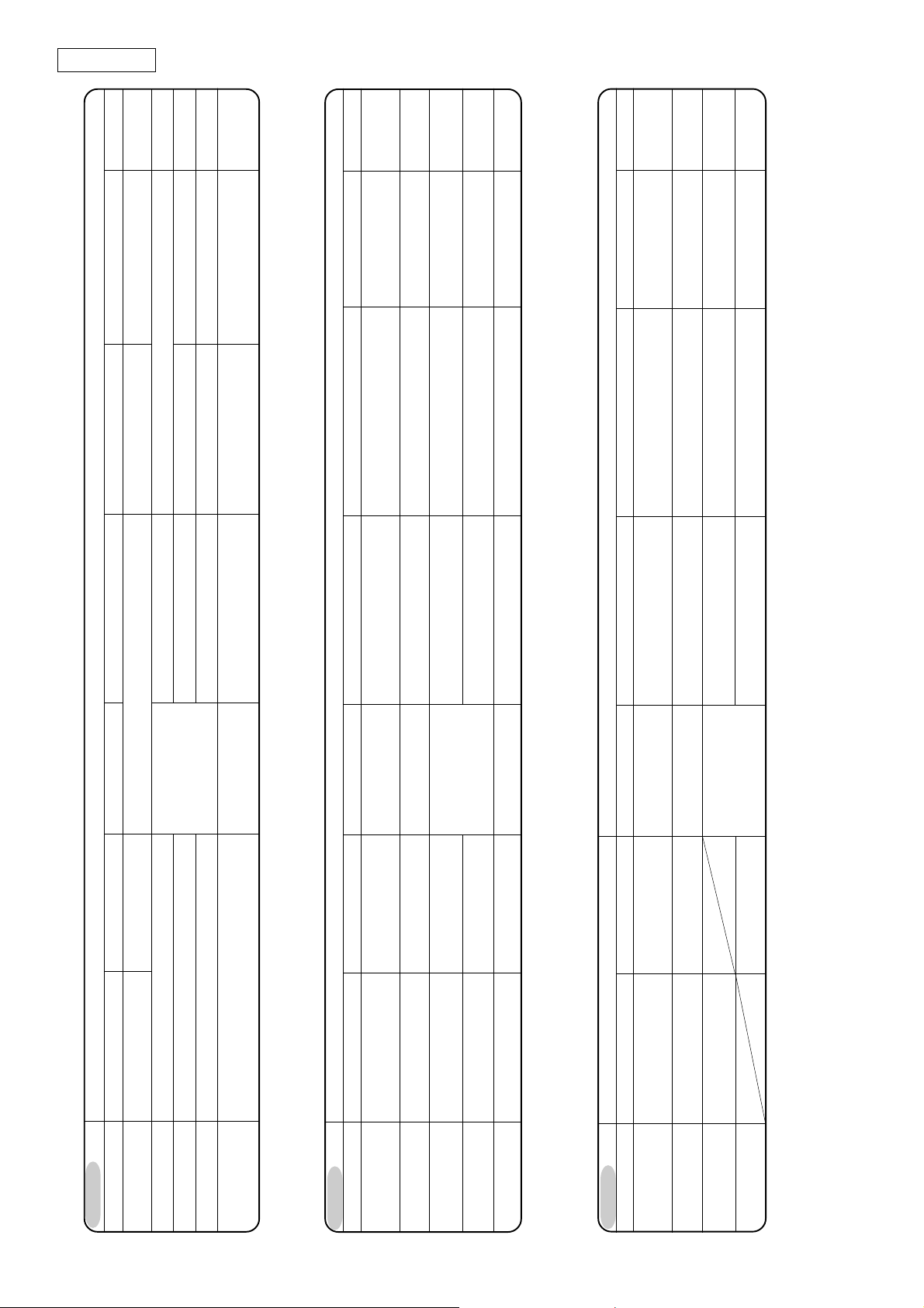
5. MICROSWITCH PROGRAMMING
ENGLISH
LEAF 1 FORCE
1 (MIN)
2
3
4
5
6
7
8 (MAX) OFF
LOGIC PAUSE (s)
E
EP
B
C
A
A
A
A
A
A
S
S
S
S
S
S
/
/
/
/
0
10
20
30
60
120
0
10
20
30
60
120
SW1
ON
OFF
ON
OFF
ON
OFF
OFF
SW7ONSW8
OFF
ON
OFF
ON
OFF
OFF
ON
OFF
ON
OFF
ON
OFF
OFF
SW3
SW2
ON
ON
ON
ON
ON
OFF
ON
OFF
OFF
ON
ON
OFF
OFFONOFF
OFF
12345 678 910 11 12
SW9
ON
ON
ON
ON
ON
OFF
OFF
ON
ON
OFF
ON
OFF
OFFONOFF
OFF
OFF
ON
ON
ON
ON
OFF
ON
OFF
ON
OFF
ON
ON
OFF
OFFONOFF
OFF
OFF
LEAF 2 FORCE
SW10
ON
ON
ON
ON
ON
ON
ON
ON
OFF
OFF
OFF
OFF
OFF
OFF
OFF
OFF
1 (MIN)
2
3
4
5
6
7
8 (MAX)
CLOSING LEAF
DELAY (s)
20
10
5
0
SW4
ON
OFF
ON
OFF
ON
OFF
SW5
ON
ON
OFF
OFF
ON
ONOFF
OFFON OFF
OFF
SW11
ON
OFF
ON
OFF
SW6
ON
ON
ON
ON
OFF
OFF
OFF
SW12
ON
ON
OFF
OFF
OPENING LEAF DELAY (s)
2
0
CLOSING PHOTOCELL LOGIC
REVERSES ON RELEASE
REVERSES IMMEDIATELY
1234
FAIL SAFE
YES
NO
REVERSING STROKE
+ OVER-PUSHING STROKE
YES
NO
SW1
ON
OFF
SW2
ON
OFF
SW3
ON
OFF
SW4
ON
OFF
DS1
Fig. 18a
The equipment is endowed with two groups of microswitches DS1 (fig. 18a) and DS2 (fig.18b) - which make it possible to program
the gate operation parameters.
5.1. MICROSWITCHES DS1 fig. 18a)
Leaf l and 2 force
By using microswitches SW1, SW2 and SW3, the force (and thus
anti-crushing safety) of the operator connected to leaf 1 can be
programmed. The same operation has to be repeated on the
motor connected to leaf 2, by using microswitches SW4, SW5 and
SW6.
N.B. As concerns the hydraulic operators, select maximum
force (level 8) on the equipment and adjust thrust with
the operator by-pass valves.
Function logic
The automated system's function logic can be selected with
microswitches SW7, SW8, SW9 and SW10. By selecting an automatic
logic (A, S), the combination of microswitches enables selection
of pause time too (waiting time, in opening position, before
automatic re-closing).
The available logics - their operation is described in tables 3/ab-c-d-e-f, are as follows: A - S (Automatic), E - EP - B (Semiautomatic), C (Dead-man).
Closing leaf delay
Programming of microswitches SW11 and SW12 enables delay of
the closing start of leaf 1 with respect to leaf 2, in order to avoid
the leaves overlapping during movement, and thus increase the
safety of the system.
DS2
Fig. 18b
5.2. MICROSWITCHES DS2 (fig. 18b)
Opening leaf delay
Programming of microswitch SW1 enables delay of the opening
start of leaf 2 with respect to leaf 1, in order to avoid the leaves
obstructing each other during the initial stage of movement.
Closing photocells logic
By using microswitch SW2, you can select the type of behaviour
of the automated system if the photocells protecting the gate
closing movement are engaged. You can obtain either immediate
reversing of the leaves or a stop followed by reversing when the
photocells are disengaged.
Fail safe
Programming the microswitch SW3 makes it possible to activate
or de-activate the photocells control test. When Fail safe is active,
the equipment checks the photocells before every opening or
closing movement.
Reversing stroke + over-pushing stroke
By using the microswitch SW4, you can activate the "reversing
stroke" and the "over-pushing stroke". The "reversing stroke" pushes
the leaves to close for a few moments before opening the gate,
thus facilitating release of the electric lock. The "over-pushing
stroke" commands a closing thrust at full force when the gate has
already reached its stop limit, thus facilitating the locking of the
electric lock.
15
Page 7

ENGLISH
6. START-UP
6.1. LED CHECK
The table below shows the status of the LEDs in relation to to the
status of the inputs.
Note the following:
Check the state of the LEDs as per Table.
Operation of the status signalling LEDs
LEDs LIGHTED OFF
OP_A Command activated Command inactive
OP_B Command activated Command inactive
STOP Command inactive Command activated
FSWCL Safety devices disengaged Safety devices engaged
FSWOP Safety devices disengaged Safety devices engaged
NB.: The status of the LEDs while the gate is at rest are shown in
bold.
Furthermore, the DL10 LED is on the board and functions as
detailed in the following table:
Gate closed at rest:
OFF
6.2. ROTATION DIRECTION AND FORCE CHECK
1) Program the microswitches of the 452 MPS control board
according to need, as shown in Chapter 5.
2) Cut power to the electronic control equipment.
3) Release the operators and manually move the gate to the
mid-point of the opening angle.
4) Re-lock the operators.
5) Restore power.
6) Send and opening command on the OPEN A input (fig.2)
and check if the gate leaves are being commanded to
open.
N.B.:If the first OPEN A pulse commands a closing, cut power and
change over the phases of the electric motor (brown and
black wires) on the 452 MPS terminal board.
7) Check power setting of the motors and, if necessary, modify
it (see Chapter 5.1).
8) Stop leaf movement with a STOP command.
9) Release the operators, close the leaves and re-lock the
operators.
6.3. LEARNING OF OPERATING TIME
WARNING: during the learning procedure, the safety devices are
disabled! Therefore any transit must be avoided in the leaf
movement area when this operation is carried out.
Opening/closing time is established by a learning procedure.
- LEARNING PROCEDURE:
Check if the leaves are closed, and then press F push-button for
one second: DL10 LED begins flashing and the leaves begin the
opening movement.
Wait for the leaf to reach the opening stop limit and then supply
an OPEN A pulse (with the radio control or with the key controlled
push-button) to stop the movement: the leaves stop and the
DL10 LED stops flashing.
The procedure has ended and the gate is ready to operate.
LED
LIGHTED
= closed contact
LED
OFF
= open contact
DL10
Gate moving or on
pause:
like indicator-light
Time learning:
flashes rapidly
6.4. PRE-FLASHING
If you wish to increase the equipment's safety level, you can
activate the pre-flashing function which enables the flashing
lamp to go on 5 seconds before the leaf starts to move.
Pre-flashing activation procedure:
1 - check if the gate is closed
2 - open and keep open the Stop contact
3 - check if the DL10 LED is OFF (if lighted, pre-flashing is
already active)
4 - briefly press the F push-button and check if the DL10 LED
lights up.
5 - close the Stop contact (DL10 goes OFF).
Procedure for disabling the function:
1 - check if the gate is closed
2 - open and keep open the Stop contact
3 - check if the DL10 LED is lighted (if OFF, pre-flashing is
already disabled)
4 - briefly press the F push-button and check if the DL10 LED
is OFF.
5 - close the Stop contact
7. AUTOMATED SYSTEM TEST
When you have finished programming, check if the system is
operating correctly.
Most important of all, check if the force is adequately adjusted
and if the safety devices are operating correctly.
16
Page 8

ENGLISH
W.L.
OP/CLOS. SAFETY DEVICECLOSING SAFETY DEVICESOPENING SAFETY DEVICES
lighted
lighted
No effect (OPEN disabled) OFF
Locks and, on release, continues opening
Locks and, on release, reverses at opening
No effect (OPEN disabled) lighted
Freezes pause until release (2) (OPEN disabled)
No effect
No effect
see paragraph 5.2. flashing
OFF
W.L.OP/CLOS. SAFETY DEVICE
No effect (OPEN disabled)
No effect
lighted
Locks and, on release, reverses at opening flashing
Closes after 5" (OPEN disabled) lighted
No effect (OPEN disabled) lighted
No effect Locks and, on release, continues opening
CLOSING SAFETY DEVICES
OFF
No effect (OPEN disabled)
OP/CLOS. SAFETY DEVICE W.L.
No effect (OPEN disabled)
No effect
lighted
lighted
Locks and, on release, continues opening
Locks and, on release, reverses at opening flashing
No effect
see paragraph 5.2.
CLOSING SAFETY DEVICES
PULSES
No effect
Reverses at closing
No effect (saves OPEN)
No effect (OPEN disabled)
STOP
Stops operation
OPEN-B
after pause time (1)
Reloads pause time (1)
Opens the free leaf and closes
Re-opens the leaf immediately (1)
No effect (1)
OPEN-A
after pause time (1)
Reloads pause time (1)
Opens leaves and closes them
Re-opens the leaves immediately (1)
PULSES
No effect (OPEN disabled) No effect
Closes the leaf/leaves
No effect
Reverses at closing
No effect (saves OPEN) see paragraph 5.2.
OPENING SAFETY DEVICES
No effect (OPEN disabled)
STOP
Stops operation
No effect (OPEN disabled) No effect
OPEN-B
closes after pause time
Opens the free leaf and
Re-opens the leaf immediately
Re-closes the leaf immediately
Closes the leaf/leaves
OPEN-A
after pause time
Opens leaves and closes them
Re-opens the leaves immediately
Re-closes the leaves immediately Re-closes the leaf immediately
Re-closes the leaves immediately
PULSES
No effect
OPENING SAFETY DEVICES
No effect (OPEN disabled)
STOP
Stops operation
OPEN-B
Opens the free leaf
Re-closes the leaf immediately
Stops operation Reverses at closing
OPEN-A
Opens the leaves
Re-opens the leaves immediately Re-opens the leaf immediately (1) No effect (saves OPEN)
Re-closes the leaves immediately
No effect (OPEN disabled) No effect No effect (OPEN disabled) lighted
Closes the leaf/leaves
(with CLOSING SAFETY DEVICES active, opens at 2nd pulse)
GATE STATUS
LOGIC "A"
Table 3/a
CLOSED
AT CLOSING
OPEN on PAUSE
LOCKED
AT OPENING
GATE STATUS
LOGIC "S"
Table 3/b
CLOSED
AT CLOSING
OPEN on PAUSE
17
LOCKED
AT OPENING
GATE STATUS
LOGIC "E"
Table 3/c
OPEN
CLOSED
AT CLOSING
LOCKED
AT OPENING
Page 9
ENGLISH
OFF
W.L.
lighted
flashing
No effect (OPEN disabled)
Locks and, on release, reverses at opening
No effect
CLOSING SAFETY DEVICES OP/CLOS. SAFETY DEVICE
lighted
lighted
Locks and, on release, continues opening
No effect
(if it must close, it disables OPEN)
OFF
W.L.
lighted
No effect
No effect
(OPEN-A disabled)
Stops operation
(OPEN-B disabled)
lighted
flashing
Stops operation
(OPEN-A/B disabled)
(OPEN-A/B disabled)
OP/CLOS. SAFETY DEVICECLOSING SAFETY DEVICESOPENING SAFETY DEVICES
No effect
No effect
(OPEN-B disabled)
(OPEN-B disabled)
No effect
Stops operation
(OPEN-B disabled)
lighted
No effect
(OPEN-A/B disabled)
W.L.
OP/CLOS. SAFETY DEVICECLOSING SAFETY DEVICESOPENING SAFETY DEVICES
No effect (OPEN-B disabled)
PULSES
OFF
lighted
No effect
No effect
(OPEN-A disabled)
No effect
(OPEN-B disabled)
Stops operation
(OPEN-B disabled)
No effect
Stops operation
(OPEN-B disabled)
lighted
flashing
Stops operation
(OPEN-A/B disabled)
(OPEN-A/B disabled)
No effect
(OPEN-B disabled)
PULSES
OPENING SAFETY DEVICES
No effect (OPEN disabled)
Reverses at closing No effect
No effect (saves OPEN)
No effect (OPEN disabled)
STOP
Stops operation
OPEN-B
Opens the free leaf
Stops operation
Stops operation see paragraph 5.2.
OPEN-A
Re-closes the leaf/leaves immediately No effect (OPEN disabled)
Opens the leaves
No effect
PULSES
No effect (OPEN disabled) No effect (if it must open, it disables OPEN) No effect (OPEN disabled)
(always closes after a Stop )
Restarts moving in reverse direction
(OPEN-A disabled)
STOP
No effect
(OPEN-A disabled)
OPEN-B
No effect
OPEN-A
Opens the leaf or leaves
No effect
No effect
(OPEN-A disabled)
No effect
Stops operation
(OPEN-B disabled)
No effect
Closes the leaves or leaf
No effect
Reverses at opening
No effect
No effect
(OPEN-A disabled)
(OPEN-A disabled)
No effect
(OPEN-A/B disabled)
No effect
Closes the leaves or leaf
No effect
Opens the leaf or leaves
No effect
(OPEN-A disabled)
STOP
No effect
(OPEN-A disabled)
OPEN-B
No effect
No effect
No effect
(OPEN-A disabled)
No effect
(OPEN-B disabled)
Closes the leaves or leaf
Stops operation
(OPEN-A disabled)
Stops operation
Stops operation
COMMANDS ALWAYS PRESSED
OPEN-A
No effect
Stops operation
Opens the leaf or leaves
GATE STATUS
LOGIC "EP"
Table 3/d
OPEN
CLOSED
LOCKED
AT OPENING
AT CLOSING
GATE STATUS
LOGIC "B"
Table 3/e
OPEN
CLOSED
LOCKED
AT OPENING
AT CLOSING
18
GATE STATUS
LOGIC "C"
Table 3/f
OPEN
CLOSED
AT OPENING
AT CLOSING
(1) If maintained, it prolongs the pause until disabled by the command (timer function)
(2) If remaining pause time is shorter than 5 sec., when safety devices are released, it closes after 5 sec.
NB.: Effects on other active pulse inputs in brackets.
 Loading...