

Page 1
Wiring / Owner’s
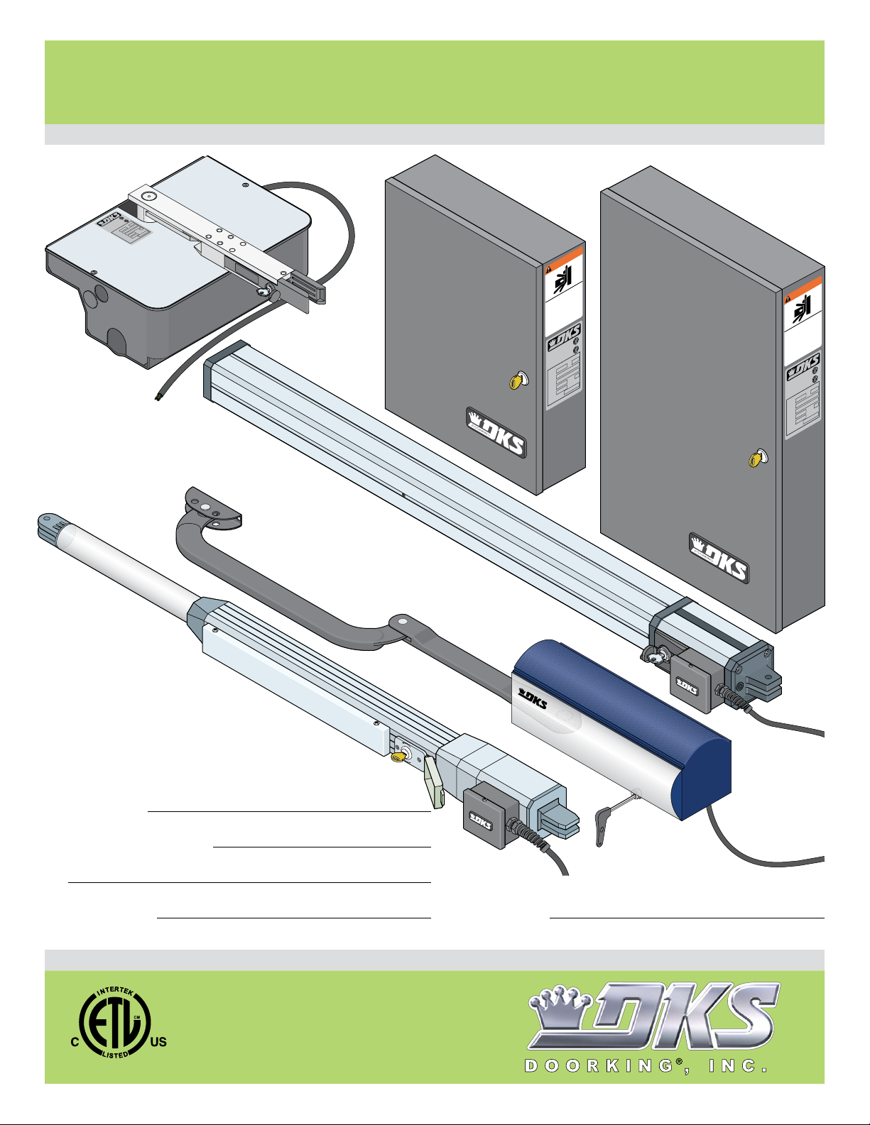
115 VAC Control Boxes for
115 VAC Control Boxes for
115 VAC Control Boxes for
Manual
6002, 6003, 6004 and 6400 gate operators
Use this manual for circuit board 4302-010 Revision A or higher.
2
8
3
3
5
O
R
T
S
5
TO
2
M
3
R
47
-
RA
2
L
O
E
O
T
/U
I
O.
NF
OP
D
S
N
O
E
P
N
C
E
H
FI
.2
A
T
2
TI
A
2
R
G
C
CE
AR
CSA
/
L
N
ASE
CA
HICU
z
VE
H
SS
A
0
L
6
L
C
E
CA
,
MOD
AL
I
R
SE
SPH
T
L
VO
S
MP
A
MA
wood
D
gle
In
OA
,
L
.
c
E
n
T
I
,
GA
g
in
X
K
r
o
o
D
Standard
Control Box
6400
WARNING
TE
A
G
URY
J
NG
I
IN
V
O
M
hen
w
ly
d
n
SERIOUS
le an
p
gate o
eo
p
t
f
o
erate
ee
Op
r
ildren
f
ch
and
te.
allow
t
path
o
e ga
n
e
t
o
at
vi
D
g
era
p
o
in
d
or
e is mo
t
stan
a
and saf
t
g
o
al
n
ile
nu
Do
wh
ma
h
’s
pat
er
Read own
T
S
5
ORM
-32
L
U
ONF
I/
C
NS
O
A
D T
NO.
IFIE
.2
RT
2
E
2
C
C
A
S
C
N/
A
AR GA
C
EHICUL
V
S
S
A
L
C
ODEL
M
L
A
RI
E
S
S
T
OL
V
D
S6
OA
P
L
M
E
A
T
GA
.,
X
Inc
A
,
M
ng
i
oorK
D
4302-065-F-1-13
USE
A
H
C
N
A
C
ht
g
OR DEAT
si
in
is
ea
r
s.
a
n
io
ate
g
ct
ea
ru
bst
e ar
o
at
g
play in
h
g
o
u
o
r
h
t
alk
w
s.
r
n
o
io
ct
ru
t
s
g.
n
in
y
et
2
8
3
53
O
47
OR
2
T
RA
E
E OP
T
HP
E
HAS
P
Hz
0
A
C
ood,
ew
Ingl
Deluxe
Control Box
Includes three 115
WARNING
TE
URY
J
ING GA
IN
OV
en
M
wh
ly
d
n
an
o
e
SERIOUS
le
p
at
g
eo
e
p
t
at
of
en
r
ee
Oper
r
ild
f
h
c
d
w
an
.
e
at
ath
t allo
o
ate g
o n
ate p
vi
D
g
o
in
oper
m
d
or
ate is
t stan
g
o
al an
n
u
ile
h
Do
w
h
’s man
r
pat
e
n
w
o
Read
TO
S
5
ORM
-32
L
ONF
C
NSI/U
O
A
D T
IE
NO.
IF
RT
2.2
E
2
C
C
A
S
A
C
G
N/
A
AR
C
L
U
HIC
VE
S
S
A
L
C
L
E
OD
M
L
A
I
R
E
S
S
T
OL
V
D
S6
OA
P
L
M
E
A
T
GA
.,
X
Inc
A
,
M
ng
i
oorK
D
E
US
A
H
C
AT
N
E
A
D
C
ght
OR
in si
ea is
s.
ar
n
e
io
at
g
ct
ea
bstru
e ar
t
o
a
g
lay in
p
gh
o
u
o
r
h
t
.
walk
r
ns
o
io
ct
ru
.
t
s
g
n
in
y
et
d saf
2
8
3
3
5
47
OR
2
T
RA
E
OP
E
T
HP
E
S
HA
P
Hz
0
A
C
ood,
ew
gl
n
I
convenience outlets.
VAC
Date Installed:
Installer/Company Name:
Phone Number:
Leave Manual with Owner
6003
6002
DO
OSE
CL
N
OPE
Circuit Board
Serial Number
and Revision Letter:
Copyright 2013 DoorKing, Inc. All rights reserved.
ORKING
6004
UL 325 Compliant
TM
Copyright 2009 DoorKing, Inc. All rights reserved.
Page 2

Page 3
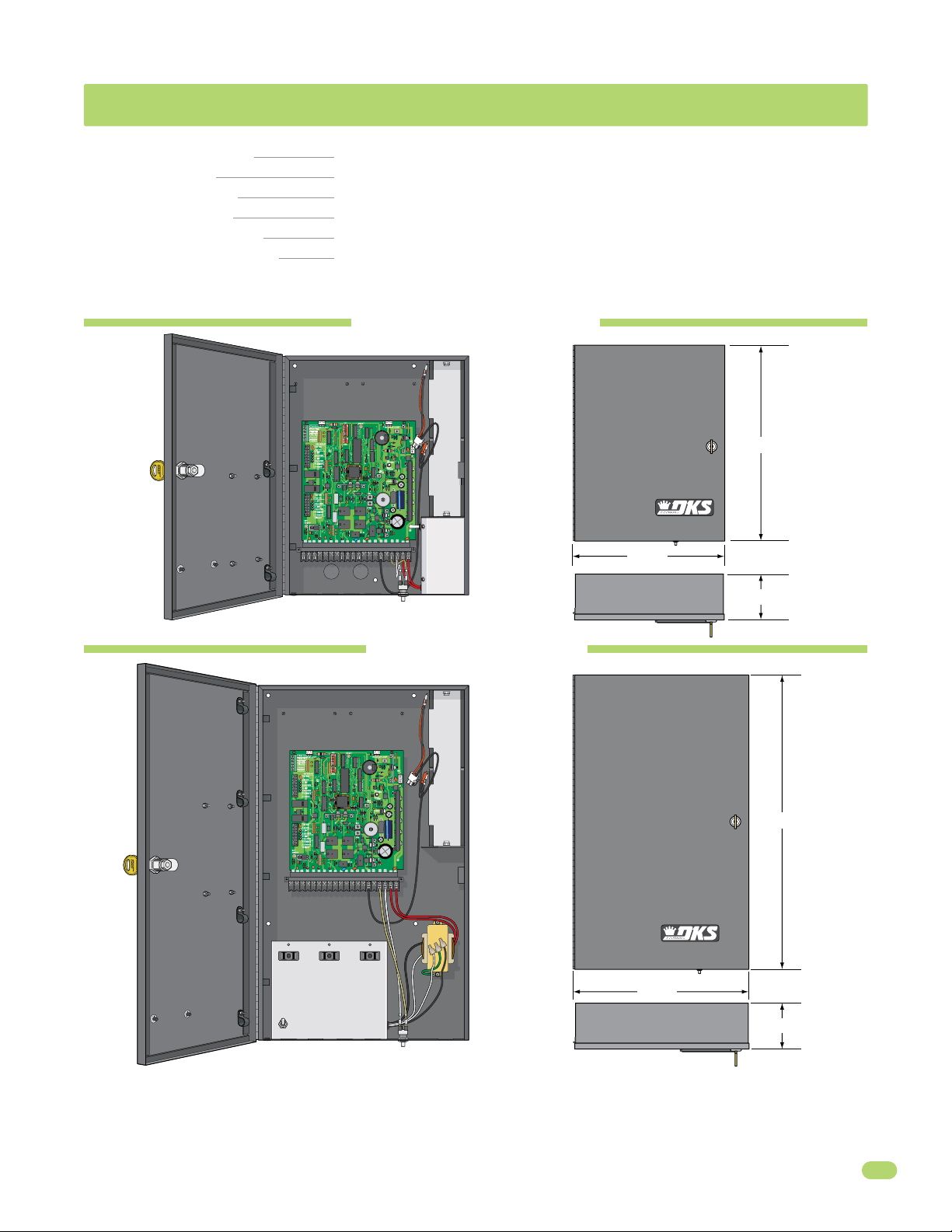
115 VAC CONTROL BOXES SPECIFICATIONS
Class of Operation Models 6002, 6003, 6004 and 6400 - UL325 Class I
Type of Gate Residential Vehicular Automated Gates Only
Voltage / Phase 115 VAC 60 Hz Single Phase Input Power – 24 VDC Output Power to Gate Operators
Back-Up Power 24 VDC battery power during power outages.
Circuit Board Model 4302-010 revision A or higher.
Entrapment Protection Primary - Inherent entrapment sensing system (Type A) (Reversing sensor)
Secondary - Provision for connection of a non-contact sensor (Type B1)
Standard Control Box
P/N 4302-111
16.5”
1
2
3
4
5
6
7
1 23 4 5 6 78 9 10111213 14151617181920
4302
12.5”
1 23 4 5 6 78 9 1011121314151617 181920
ON
OFF
4.25”
Deluxe Control Box
P/N 4302-112
24.5”
4302
14.5”
4.25”
115 VAC convenience outlets to
power auxiliary power transformers.
DoorKing, Inc. reserves the right to make changes in the products described in this manual without notice and without obligation of DoorKing, Inc. to notify any persons
of any such revisions or changes. Additionally, DoorKing, Inc. makes no representations or warranties with respect to this manual. This manual is copyrighted, all rights
reserved. No portion of this manual may be copied, reproduced, translated, or reduced to any electronic medium without prior written consent from DoorKing, Inc.
4302-065-F-1-13
1
Page 4

TABLE OF CONTENTS
SPECIFICATIONS 1
115 VAC Control Boxes Specifications
ASTM F2200 Standard for Gate Construction
Important Safety Instructions
Instructions regarding intended installation:
Important Notices
UL 325 Entrapment Protection
Glossary
Swing Gate Requirements
Swing Gate Protection
3-4
SECTION 1 - WIRING 9
1.1 Control Box Wiring Overview
1.1 Wiring Operators to 4302 Circuit Board
1.2 Secondary Entrapment Protection Wiring
1.3 Main Terminal Description
1.4 Main Terminal Wiring
1.5 Loop Detector Wiring
1.6 High Voltage Wiring and Battery Connection
10
11
12
13
14
15
SECTION 2 - ADJUSTMENTS 16
1
3
3
4
5
6
7
8
9
2.1 3402 Circuit Board Description and Adjustments
2.2 DIP-Switches
2.3 Limit Sensors Adjustment - Select your specific operator
6002 Limit Sensors ONLY
6003 Limit Sensors ONLY
6004 Limit Sensors ONLY
6400 Limit Sensors ONLY
2.4 Inherent Reverse Sensor Adjustment
2.5 Shutdown Conditions
Soft Shutdown
Hard Shutdown (Alarm Activated)
16
17-18
19-21
21
22-23
SECTION 3 - MAINTENANCE AND TROUBLESHOOTING 24
3.1 Maintenance
3.2 Diagnostics Check
3.3 Troubleshooting
3.4 Accessory Items
115 VAC Standard or Deluxe Control Box Schematics
IMPORTANT INFORMATION FOR OWNER
24
24-25
26-27
27
28
29
Shut-Off ALL Power to Operator OR Shut-OFF Alarm
Manually Operating the Gate (NO Power)
2
29
30
4302-065-F-1-13
Page 5

ASTM F2200 Standard for Gate Construction
Vehicular gates should be constructed and installed in accordance with ASTM F2200; Standard Specification for Automated
Vehicular Gate Construction. For a copy of this standard, contact ASTM directly at 610-832-9585; service@astm.org; or
www.astm.org.
Important Safety Instructions
WARNING - To reduce the risk of injury or death:
1. READ AND FOLLOW ALL INSTRUCTIONS.
2. Never let children operate or play with gate controls. Keep the remote control away from children.
3. Always keep people and objects away from gate. NO ONE SHOULD CROSS THE PATH OF THE MOVING GATE.
4. Test the operator monthly. The gate MUST reverse on contact with a rigid object or stop or reverse when an object
activates the non-contact sensors. After adjusting the force or the limit of travel, retest the gate operator. Failure to adjust
and retest the gate operator properly can increase the risk of injury or death.
5. Use the emergency release only when the gate is not moving.
6. KEEP GATES PROPERLY MAINTAINED. Read the owner's manual. Have a qualified service person make repairs to gate
hardware.
7. The entrance is for vehicles only. Pedestrians must use separate entrance.
8. SAVE THESE INSTRUCTIONS!
Instructions regarding intended installation:
• Install the gate operator only if:
1. The operator is appropriate for the construction of the gate and the usage class of the gate.
2. All openings of a horizontal slide gate are guarded or screened from the bottom of the gate to a minimum of 6 feet
(1.83 m) above the ground to prevent a 2 ¼ inch (57.2 mm) diameter sphere from passing through the openings
anywhere in the gate, and in that portion of the adjacent fence that the gate covers in the open position.
3. All exposed pinch points are eliminated or guarded.
4. Guarding is supplied for exposed rollers.
• The operator is intended for installation only on gates used for vehicles. Pedestrians must be supplied with a separate
access opening. The pedestrian access opening shall be designed to promote pedestrian usage. Locate the gate such that
persons will not come in contact with the vehicular gate during the entire path of travel of the vehicular gate.
• The gate must be installed in a location so that enough clearance is supplied between the gate and adjacent structures
when opening and closing to reduce the risk of entrapment. Swinging gates should not open into public access areas.
• The gate must be properly installed and work freely in both directions prior to the installation of the gate operator. Do not
over-tighten the operator clutch, pressure relief valve or reduce reversing sensitivity to compensate for a damaged gate.
• For gate operators utilizing Type D protection:
1. The gate operator controls must be placed so that the user has full view of the gate area when the gate is moving.
2. A warning placard shall be placed adjacent to the controls.
3. An automatic closing device (such as a timer, loop sensor, or similar device) shall not be employed.
4. No other activation device shall be connected.
• Controls intended for user activation must be located at least ten feet (10’) away from any moving part of the gate and
where the user is prevented from reaching over, under, around or through the gate to operate the controls. Outdoor or
easily accessible controls should have a security feature to prevent unauthorized use.
• The Stop and/or Reset button must be located in the line-of-sight of the gate. Activation of the reset control shall not
cause the operator to start.
• A minimum of two (2) WARNING SIGNS shall be installed, one on each side of the gate where easily visible.
• For gate operators utilizing a non-contact sensor:
1. See the instructions on the placement of non-contact sensors for each type of application.
2. Care shall be exercised to reduce the risk of nuisance tripping, such as when a vehicle trips the sensor while the gate
is still moving in the opening direction.
3. One or more non-contact sensors shall be located where the risk of entrapment or obstruction exist, such as the
perimeter reachable by a moving gate or barrier.
4302-065-F-1-13
3
Page 6

• For gate operators utilizing contact sensors:
1. One or more contact sensors shall be located where the risk of entrapment or obstruction exist, such as at the
leading edge, trailing edge, and post mounted both inside and outside of a vehicular horizontal slide gate.
2. One or more contact sensors shall be located at the bottom edge of a vehicular vertical lift gate.
3. One or more contact sensors shall be located at the pinch point of a vehicular vertical pivot gate.
4. A hardwired contact sensor shall be located and its wiring arranged so that the communication between the sensor
and the gate operator is not subjected to mechanical damage.
5. A wireless contact sensor such as one that transmits radio frequency (RF) signals to the gate operator for
entrapment protection functions shall be located where the transmission of the signals are not obstructed or
impeded by building structures, natural landscaping or similar obstructions. A wireless contact sensor shall function
under the intended end-use conditions.
6. One or more contact sensors shall be located at the bottom edge of a vertical barrier (arm).
Important Notices
Vehicular gate operator products provide convenience and security. However, gate operators must use high levels of force
to move gates and most people underestimate the power of these systems and do not realize the potential hazards associated with an incorrectly designed or installed system. These hazards may include:
• Pinch points
• Entrapment areas
• Reach through hazards
• Absence of entrapment protection devices
• Improperly located access controls
• Absence of vehicle protection devices
• Absence of controlled pedestrian access
In addition to these potential hazards, automated vehicular gate systems must be installed in accordance with the UL 325
Safety Standard and the ASTM F2200 Construction Standard. Most lay persons are unaware of, or are not familiar with,
these standards. If an automated vehicular gate system is not properly designed, installed, used and maintained, serious
injuries or death can result. Be sure that the installer has instructed you on the proper operation of the gate and gate
operator system.
Be sure that the installer has trained you about the basic functions of the required reversing systems associated with your
gate operating system and how to test them. These include reversing loops, inherent reversing system, electric edges,
photoelectric cells, or other external devices.
• This Owner’s Manual is your property. Keep it in a safe place for future reference.
• Be sure that all access control devices are installed a minimum distance of 10 feet away from the gate and gate
operator, or in such a way that a person cannot touch the gate or gate operator while using the device. If access
control devices are installed in violation of these restrictions, immediately remove the gate operator from service
and contact your installing dealer.
• Loops and loop detectors, photo-cells or other equivalent devices must be installed to prevent the gate from
closing on vehicular traffic.
• The speed limit for vehicular traffic through the gate area is 5 MPH. Install speed bumps and signs to keep
vehicular traffic from speeding through the gate area. Failure to adhere to posted speed limits can result in
damage to the gate, gate operator, and to the vehicle.
• Be sure that all persons who will use the gate system are familiar with the proper use of the gate and gate
operator and are familiar with the possible hazards associated with the gate system.
• Be sure that warning signs are permanently installed on both sides of the gate in an area where they are fully
visible to traffic.
• It is your responsibility to periodically check all entrapment protection devices. If any of these devices are
observed to function improperly, remove the operator from service immediately and contact your installing or
servicing dealer.
• Follow the recommended maintenance schedule.
• Do not allow children to play in the area of the operator or to play with any gate-operating device.
• To remove the gate operator from service, operate the gate to the full open position and then shut off power to
the operator at the service panel.
4
4302-065-F-1-13
Page 7
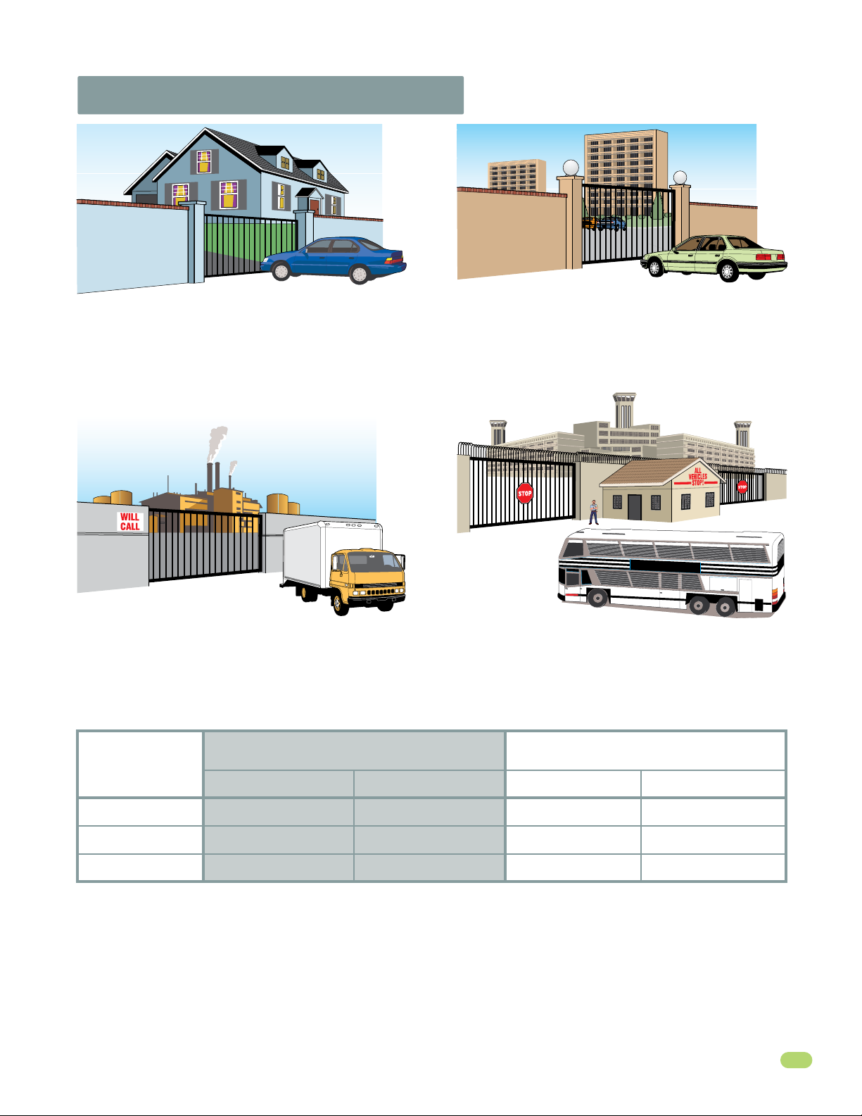
UL 325 Entrapment Protection
Class I
A vehicular gate operator (or system) intended for use in a
home of one-to four single family dwelling, or a garage or
parking area associated therewith.
Class II
A vehicular gate operator (or system) intended for use in a
commercial location or building such as a multi-family
housing unit (five or more single family units) hotel,
garages, retail store or other building servicing the general
public.
Class III Class IV
A vehicular gate operator (or system) intended for use in a
industrial location or building such as a factory or loading
dock area or other locations not intended to service the
general public.
A vehicular gate operator (or system) intended for use in a
guarded industrial location or building such as an airport
security area or other restricted access locations not
servicing the general public, in which unauthorized access
is prevented via supervision by security personnel.
STATE PRISON
This table illustrates the entrapment protection requirements for each of the four UL 325 classes.
Classifications
Class I and II
Class III
Class IV
4302-065-F-1-13
UL 325
A - Inherent entrapment protection system.
B1 - Provision for connection of, or supplied with, a non-contact sensor (photoelectric sensor or the equivalent).
When used as the PRIMARY device, must be monitored.
B2 - Provision for connection of, or supplied with, a contact sensor (edge device or the equivalent).
When used as the PRIMARY device, must be monitored.
C - Inherent adjustable clutch or pressure relief device.
D - Provision for connection of, or supplied with, an actuating device requiring continuous pressure to maintain
opening or closing motion of the gate.
E - An inherent audio alarm.
Horizontal Slide, Vertical Lift, Vertical Pivot Swing and Vertical Barrier (arm)
Primary Protection
A B1, B2 or D A, B1, B2, C or D A or C
A, B1 or B2 A, B1, B2, D or E A, B1, B2, C or D A, B1, B2 or C
A, B1, B2 or D A, B1, B2, D or E A, B1, B2, C, D or E A, B1, B2, C or D
Secondary Protection Primary Protection Secondary Protection
5
Page 8

Glossary
GATE - A moving barrier such as a swinging, sliding, raising, lowering, or the like, barrier, that is a stand-alone passage
barrier or is that portion of a wall or fence system that controls entrance and/or egress by persons or vehicles and
completes the perimeter of a defined area.
RESIDENTIAL VEHICULAR GATE OPERATOR – CLASS I - A vehicular gate operator (or system) intended for use in a home
of one-to four single family dwelling, or garage or parking area associated therewith.
COMMERCIAL / GENERAL ACCESS VEHICULAR GATE OPERATOR - CLASS II - A vehicular gate operator (or system)
intended for use in a commercial location or building such as a multi-family housing unit (five or more single family units),
hotels, garages, retail store, or other building servicing the general public.
INDUSTRIAL / LIMITED ACCESS VEHICULAR GATE OPERATOR - CLASS III - A vehicular gate operator (or system)
intended for use in an industrial location or building such as a factory or loading dock area or other locations not intended
to service the general public.
RESTRICTED ACCESS VEHICULAR GATE OPERATOR - CLASS IV - A vehicular gate operator (or system) intended for use in
a guarded industrial location or building such as an airport security area or other restricted access locations not servicing
the general public, in which unauthorized access is prevented via supervision by security personnel.
VEHICULAR BARRIER (ARM) OPERATOR (OR SYSTEM) - An operator (or system) that controls a cantilever type device (or
system), consisting of a mechanical arm or barrier that moves in a vertical arc, intended for vehicular traffic flow at
entrances or exits to areas such as parking garages, lots or toll areas.
VEHICULAR HORIZONTAL SLIDE-GATE OPERATOR (OR SYSTEM) - A vehicular gate operator (or system) that controls a
gate which slides in a horizontal direction that is intended for use for vehicular entrance and exit to a drive, parking lot, or
the like.
VEHICULAR SWING-GATE OPERATOR (OR SYSTEM) - A vehicular gate operator (or system) that controls a gate which
moves in an arc in a horizontal plane that is intended for use for vehicular entrance and exit to a drive, parking lot, or the
like.
SYSTEM - In the context of these requirements, a system refers to a group of interacting devices intended to perform a
common function.
WIRED CONTROL - A control implemented in a form of fixed physical interconnections between the control, the associated
devices, and an operator to perform predetermined functions in response to input signals.
WIRELESS CONTROL - A control implemented in means other than fixed physical interconnections (such as radio waves or
infrared beams) between the control, the associated devices, and an operator to perform predetermined functions in
response to input signals.
INHERENT ENTRAPMENT PROTECTION SYSTEM - A system, examples being a motor current or speed sensing system,
which provides protection against entrapment upon sensing an object and is incorporated as a permanent and integral part
of the operator.
EXTERNAL ENTRAPMENT PROTECTION DEVICE - A device, examples being an edge sensor, a photoelectric sensor, or
similar entrapment protection device, which provides protection against entrapment when activated and is not incorporated
as a permanent part of an operator.
ENTRAPMENT - The condition when an object is caught or held in a position that increases the risk of injury.
6
4302-065-F-1-13
Page 9
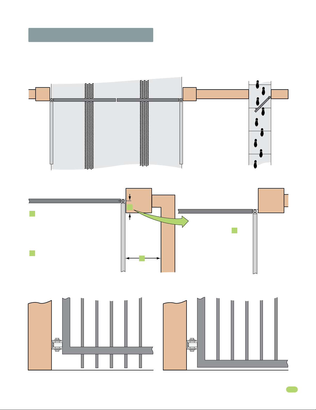
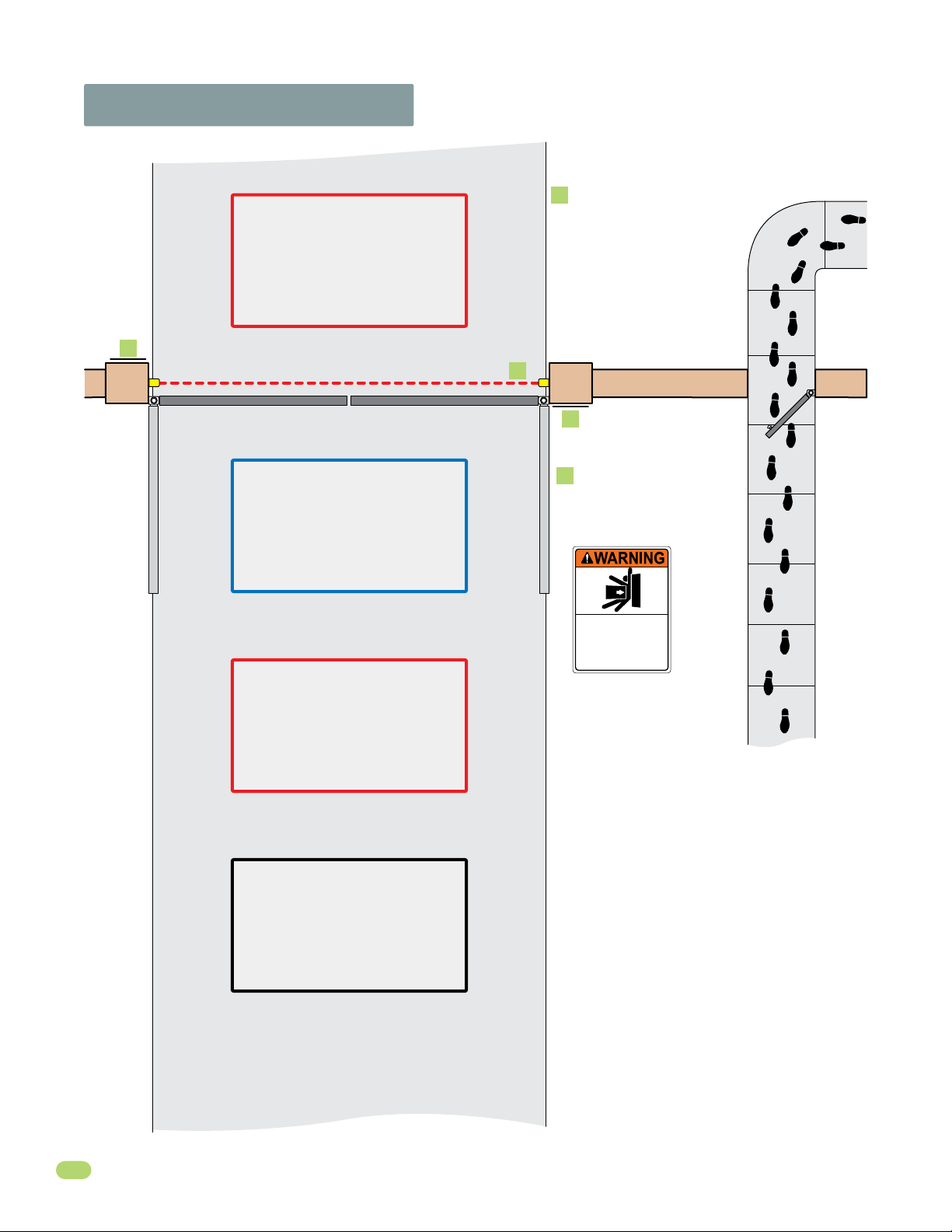
Swing Gate Requirements
The operator is intended for installation only on gates used for vehicles. Pedestrians must be supplied with a separate
access opening. The pedestrian access opening shall be designed to promote pedestrian usage. Locate the gate such that
persons will not come in contact with the vehicular gate during the entire path of travel of the vehicular gate.
(ref. UL325 56.8.4.b)
Closed Gates
Closed Gate
If distance is greater than 4 inches,
A
entrapment protection for this area is
required. ASTM F2200 7.1.1.1
If distance is less than 16 inches,
B
entrapment protection in this area
is required. ASTM F2200 7.1.1.2
Not Allowed OK
A
B
Opened Gate
Closed Gate
With the hinge mounted on
the corner of the pilaster,
the entrapment area is
eliminated and protection
is NOT required for this
area.
A
Opened Gate
Gates shall have smooth bottom edges, with vertical bottom edged protrusions not exceeding 0.50 inches. ASTM F2200 4.3
4302-065-F-1-13
7
Page 10
Swing Gate Protection
Reverse Loop
Minimizes the potential of the gate
closing when a vehicle is present.
Number and placement of loops is
dependent on the application.
D
Shadow Loop
Provides a hold open command to
the operator(s) only if the gate(s)
are at the full open position.
C
Non-contact Sensor
Minimizes the potential
of the gate closing on
vehicular or other traffic
that loops cannot sense.
C
D
D
Warning Signs
Permanently mounted
and easily visible from
either side of the gate.
Reverse Loop
Minimizes the potential of the gate
closing when a vehicle is present.
Number and placement of loops is
dependent on the application.
Automatic Exit Loop
(Optional) will provide an open
command to the gate operator(s)
when a vehicle is exiting the
property.
Moving Gate Can Cause
Serious Injury or Death
KEEP CLEAR! Gate may move at any time
without prior warning.
Do not let children operate the gate or play
in the gate area.
This entrance is for vehicles only.
Pedestrians must use separate entrance.
Separate Pedestrian
Walkway
Located so pedestrians
cannot come in contact
with the vehicular gate.
8
4302-065-F-1-13
Page 11
SECTION 1 - WIRING
Before attempting to connect any wiring to the control box, be sure that the circuit breaker in the electrical panel is in the OFF
position. Permanent wiring must be installed to the control box as required by local electrical codes. It is recommended that a
licensed electrical contractor perform this work.
Since building codes vary from city to city, we highly recommend that you check with your local building department prior
to installing any permanent wiring to be sure that all wiring to the control box (both high and low voltage) complies with
local code requirements.
THIS CONTROL BOX MUST BE PROPERLY GROUNDED!!
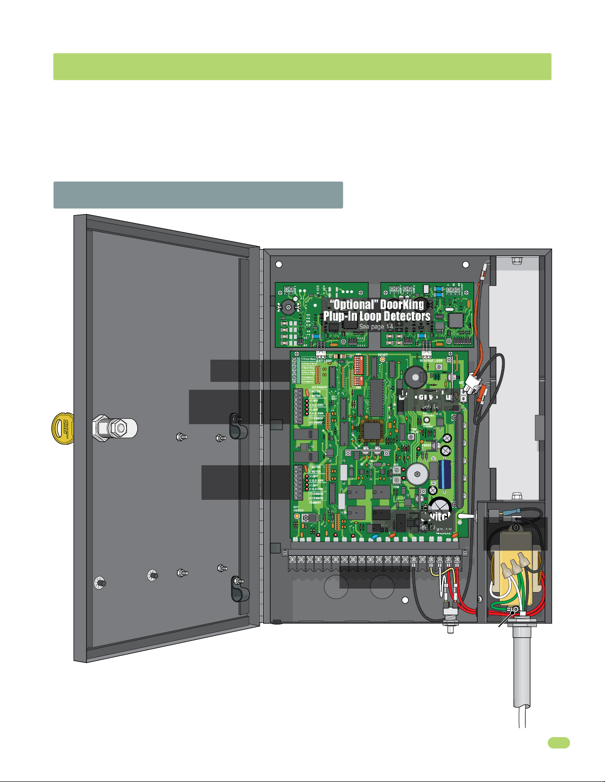
1.1 Control Box Wiring Overview
“Optional” DoorKing
Plup-In Loop Detectors
UL 325 Terminal
See page 11.
See page 14.
12 Volt 3 Amp/Hr Battery12 Volt 3 Amp/Hr Battery
SECONDARY Operator
Connection ONLY
See page 10.
PRIMARY Operator
Connection ONLY
See page 10.
1
2
3
4
5
6
7
1234567
Battery Plug
AC Power Switch
10 11 121314 15
89
Main Terminal
See pages 12-13.
See page 15.
See page 15.
16 17 18 19
20
Chassis
Ground
See page 15.
AC Power
Connection
See page 15.
BLK 115V WHT
RED 24V RED
Conduit
4302-065-F-1-13
Input Power Wire
See page 15.
9
Page 12

1.2 Wiring Operators to 4302 Circuit Board
Primary or Secondary
Operator Cable Terminal
Brown Wire
Blue Wire
Orange Wire
Red Wire
Yellow Wire
Green Wire
Green/Yellow Wire
Not Used
1
2
3
4
5
6
7
8
Operator Terminal Note: The 8-pin
terminals can be unplugged from
circuit board for easy wire connections.
1
2
3
4
Secondary Operator ONLY
5
6
7
1
2
3
4
Primary Operator ONLY
5
6
7
Secondary Operator Cable
(Interconnection cable)
6400 Dual Operator Wiring ONLY!
Secondary operator motor wires MUST
be reversed from the primary operator.
Green/Yellow wire
10
1234567
Primary Operator Cable
Brown wire
Blue wire
Orange wire
Red wire
Yellow wire
Green wire
Not Used
6400 Primary
operator wiring
1
2
3
4
5
6
7
8
PRIMARY
89
10 11 12
13
Blue wire
Brown wire
Orange wire
Red wire
Yellow wire
Green wire
Green/Yellow wire
Not Used
14 15
16 17 18 19
6400 Secondary
operator wiring
1
2
3
4
5
6
7
8
20
SECONDARY
4302-065-F-1-13
Page 13

1.3 Secondary Entrapment Protection Wiring
1
5
In addition to the inherent entrapment sensing system, this operator has provisions for the connection of a non-contact (type
B1) secondary entrapment protection device. This is required by UL 325 standards.
Entrapment protection devices are required to reduce the risk of injury. Install sensors where the risk of entrapment or
obstruction exists while gate is moving.
UL 325 Terminal
PHOTO OPEN (Photo Sensors)
Stops gate movement in the open cycle. Gate resumes
normal operation when the input (obstruction) is cleared.
Not used
Not used
Not used
COMMON
Terminal for the secondary entrapment device input.
COMMON
Not used.
1
2
3
4
5
6
UL 325 Terminal Note: The 6-pin
terminal can be unplugged from circuit
board for easy wire connections.
UL 325 Terminal
Opening -Direction
Entrapment Protection
4302-065-F-1-13
Open Gate
Photo Sensors
Closed Gates
Closing-Direction Protection
When closing-direction gate’s
photo beam get obstructed,
gates will reverse back to the
full open position.
Open Gate
Closing-Direction
Protection
ON
1
2 3 4 5 6 7 8
SW 1
Switch 5 Must be OFF
Entrapment Protection
Opening -Direction
Standard Reverse input on Terminal
#8 functions ONLY while the gate is
at the FULL OPEN position or during
the CLOSING cycle. It MUST NOT be
used as an input for a secondary
entrapment protection device during
the OPENING gate cycle.
1 2 3 4 5 6 7
Standard Reverse
Low Voltage Common
Main Terminal
10 11 12
89
13
14 15
4302
16 17 18 19
20
11
Page 14

1.4 Main Terminal Description
For specific wiring information, see next page.
12345
Low Voltage Common
24 VDC - 250 ma max.
Full Open
Low Voltage Common
Full Open
7
6
Low Voltage Common
Full Open
2
• When gate is closed, input will open gate.
• When gate is open and auto close
timer SW 1, switch 4 is turned ON,
input will re-set and hold timer.
• When gate is open and auto close
timer SW 1, switch 4 is turned OFF,
input will close gate.
• When gate is closing, input will
reverse gate.
1
2 3 4 5 6 7 8
SW 1
89
Low Voltage Common
Standard Reverse
ON
8
10 11 12
Dry Relay Contact
Dry Relay Contact
24 VDC Maglock Power
10
11
Operation of the relay is dependent on the setting
of SW 2, switches 1 and 2. Relay contact can be
set for Normally Open (NO) or Normally Closed
(NC) operation. Contact rating is 1 amp
maximum at 24 Volts.
• SW 2, Switch 1 OFF, Switch 2 OFF:
Relay activates when gate is OPEN.
14 15
13
Not Used
DC Lock Power Common
12
16 17 18 19
Not Used
12 Volt Battery
DC power is not present on the
15
board until first initial cycle of gate.
Maglock: SW 2,
Switch 3 ON, 1 sec.
delay at start.
Alarm Reset
Low Voltage Common
NO
20
24 VAC Input
24 VAC Input
1
2 3 4
1
2 3 4
SW 2
NC
ON
SW 2
ON
• When gate is closed, this input has no
affect on the gate operator.
• When gate is open and auto close
timer SW 1, switch 4 is turned ON,
input will re-set and hold timer.
• When gate is open and auto close
timer SW 1, switch 4 is turned OFF,
input will prevent gate from closing.
• When gate is closing, input will
reverse gate when SW 1, switch 5
is OFF.
• SW 1, switch 5 ON is NOT used.
12
1
2 3 4 5 6 7 8
1
2 3 4 5 6 7 8
SW 1
SW 1
ON
ON
• SW 2, Switch 1 OFF, Switch 2 ON:
Relay activates when gate is OPEN, OPENING or CLOSING.
• SW 2, Switch 1 ON, Switch 2 OFF:
Relay activates when gate is OPEN or OPENING.
• SW 2, Switch 1 ON, Switch 2 ON:
Relay activates when gate is OPENING or CLOSING.
• SW 1, switch 3 is ON, terminal #4
4
functions as a normal FULL open input
(Normal Setting).
• SW 1, switch 3 is OFF, terminal #4
becomes the output from a plug-in loop
detector installed in the EXIT loop port
of the circuit board.
1
2 3 4 5 6 7 8
ON
SW 1
4302-065-F-1-13
Page 15

1.5 Main Terminal Wiring
Controls must be far enough from the gate so that the user is prevented from coming in contact with the gate while operating
the controls. Outdoor or easily accessible controls should have a security feature to prevent unauthorized use. When installing
electrical equipment make certain all wiring complies with local code requirements. Do not power any control devices from the
circuit board other than low voltage devices.
For individual terminal descriptions, see previous page.
12345
Relay Com
Relay N.O.
24 Volt Power Com
2. Relay
1. Com
P/N 8055-08
3-Wire RF Receiver
24 Volt Power
RF Receiver
3. 24 Volt
1
4-Wire
control box.
15 ft Coax
Coax Antenna Kit
6
Antenna
mounted
outside
P/N 1514-073
7
89
10 11 12
13
Reversing input on Terminal #8
functions ONLY while the gate is at
the FULL OPEN position or during
the CLOSING cycle. It MUST NOT be
used as an input for a secondary
entrapment protection device during
the OPENING gate cycle. Refer to
Section 1.3, page 11 Secondary
Entrapment Protection Wiring.
14 15
#13 Com
#12 N.C.
16 17 18 19
20
Magnetic Lock
ON
1
2 3 4
SW 2
Switch 3 ON
Note: Circuit board provides
24 VDC to power maglock.
Contact rating is 1 amp
maximum at 24 Volts.
Safety Opening Device
(Dry contact)
#7 - Com
#6 - N.O.
4302-065-F-1-13
Mount inside of
control box door.
Connect optional control devices
to the main terminal. Use 18 AWG
wire for all low voltage wiring,
maximum distance 3000 feet. Use
a low voltage surge suppressor,
(DoorKing P/N 1878-010) if low
voltage wire runs exceed 1000
feet. All control device inputs to
the terminal must be NORMALLY
OPEN.
Deluxe Control Box ONLY
Three 115 VAC Convenience Outlets.
Power safety and opening devices
that require 115 VAC power.
#5 - Com
#4 - N.O.
#5 - Com
#4 - N.O.
#4 - N.O.
#5 - Com
Keypad
(Dry contact)
SW 1,
Switch 3 ON
ON
1
2 3 4 5 6 7 8
Key Switch
(Dry contact)
SW 1
Telephone
Entry
Note: Telephone entry device must
use a separate power source.
13
Page 16

1.6 Loop Detector Wiring
To help protect the operator from accidentally closing on vehicles in the gate’s path, DoorKing highly recommends that loops
and loop detectors are used. A loop detection system will sense a vehicle like a metal detector and send a signal to the gate
operator preventing the gate from automatically opening or closing on a vehicle when it is in the gate’s path. DoorKing recommends that a licensed installer perform this work.
DoorKing offers a free “Loop and Loop-
Shadow Loop The shadow loop is only active
when the gate is in the full open position. Vehicles in
the shadow area will activate it. It will not allow the
gate to close unless this area is clear. After a closing
cycle begins, the shadow loop will not reverse the
gate. Reverse loops work in conjunction with the
shadow loop and both type loops should be used.
Detectors Information Manual” PDF located
at Doorking’s web site for more information.
www.dkaccess.com
Reverse
Shadow loop
A
lead-in wires are
PVC conduit to
Control box.
twisted approx.
6 twists per foot.
LOOP 2
Automatic Exit
Reverse Loops
Reverse loops prevent the gate
from closing on a vehicle in or
near the gate’s swing pathway.
Reverse loop
lead-in wires are
PVC conduit to
Control box.
twisted approx.
B
6 twists per foot
and are wired in
series.
LOOP 1
Automatic Exit Loop
Automatically opens the gate for exiting
vehicles without having to use a transmitter
or keypad (Free exit).
Shadow
Reverse
B AC
9410
Single Channel Dual Channel
The circuit board relay is
used for the shadow loop
and must be set to N.O.
NC
NO
Secure Side
Inside Propert
Com
N.O.
9409
Non-Secure
Side
Outside
Propert
y
y
Loop detector wiring is
shown for DoorKing
plug-in loop detectors
P/N 9409-010 and P/N
9410-010 only. If other
loop detectors are used,
refer to the installation
instructions supplied
with those detectors for
wiring and separate
power instructions.
Shadow Loop Output
Shadow Loop
DIP-Switch Settings
ON
1
2 3 4 5 6 7 8
SW 1, switch 5
is OFF.
Exit loop lead-in
C
wires are twisted
PVC conduit to
Control box.
1234567
Standard Reverse
Low Voltage Common
Dry Relay Contact
Dry Relay Contact
10 11 121314 15
8 9
approx. 6 twists
per foot.
LOOP 1
14
4302
16 17 18 19
SW 1
ON
1
20
2 3 4
SW 2, switch 1
is ON and
switch 2 is OFF.
SW 2
4302-065-F-1-13
Page 17

1.7 High Voltage Wiring and Battery Connection
CONTROL BOX MUST BE PROPERLY GROUNDED!!
CAUTION
Do not connect the battery to
the circuit board until power
Reset Button
1
2
3
4
5
6
7
is needed to test the operator.
Battery Plug
12 Volt 3 Amp/Hr Battery12 Volt 3 Amp/Hr Battery
To Cycle Operator:
After power has been connected, activate the
operator by pressing the key switch button.
DO NOT cycle operator before DIP-switches
and limit sensors have been adjusted,
damage could occur to gate and operator
(See pages 17-21 to adjust DIP-switches and
limit sensors).
Important Power Note: To turn-off
ALL power to the operator, the AC
power switch must be turned off AND
the battery plug must be disconnected
from the circuit board.
AC Power Switch
1234567
Input Power Wire Table
Wire Size
14 AWG
12 AWG
DoorKing recommends that a surge
suppressor be installed on the high
voltage power lines.
P/N 1879-080
10 11 121314 15
89
Connect 115 VAC input power wires:
Black to transformer’s black (Hot).
White to transformer’s white (Neutral).
Green to chassis ground.
Distance
Up to 200 ft
Beyond 200 ft
4302
16 17 18 19
Alarm
Reset
Button
20
BLK 115V WHT
Chassis
Ground
DANGER
HIGH VOLTAGE!
External
Power
Disconnect
Note: A separate power
disconnect switch may be
needed in your area. Check
local building codes before
Switch
installation.
Conduit
AC POWER
ON
OFF
Input
Power
Wire
RED 24V RED
4302-065-F-1-13
15
Page 18

SECTION 2 - ADJUSTMENTS
The switch settings and adjustments in this section should be made after your installation and wiring to the operator(s) is
complete. Whenever any programming or switch setting on the control board are changed, press the reset switch for new
settings to take effect.
2.1 4302 Circuit Board Description and Adjustments
Plug-In Loop Detector Plug-In Loop Detector
9410 Single Channel 9409 Dual Channel
DIP-Switches
ON
1
2 3 4 5 6 7 8
Set DIP-switches
on the circuit
board to the
desired setting.
See switch-setting
charts on next 2
pages.
Self Test
1
2 3 4
SW 2
SW 1
ON
UL 325 Terminal
See page 11.
Limit LEDs
Self test mode is
Self Test
Mode
for bench checks
ONLY. The
operator will
continually cycle
See page 10.
Operator
SECONDARY
the gate.
Limit LEDs
The jumper must
be set at normal
Normal
mode to function.
Mode
PRIMARY
See pages 19-20.
See page 10.
Operator
Input LEDs
1 2 3 4 567
Cycles the operator when
pressed. Will use Auto-Close
timer when turned ON.
Dry Relay Contact
Dry relay contacts (terminals 10-11) can
be set for Normally Open (NO) or
Normally Closed (NC) operation by
placing the relay shorting bar on the N.O.
or N.C. pins respectively.
(Shadow loop function if used, N.O., see page 14).
NO
NC
See page 14.
Main Terminal See pages 12-13.
10 11 121314 15
8 9
Turns
alarm
OFF.
Alarm Reset
Button
Reverse Loop PortExit Loop Port
4302
16 17 18 19
See
page
24.
How LEDs Function
Illuminated LEDs
Indicates that low voltage
power is being applied to
the circuit board.
Input LEDs should be OFF and
will only illuminate when the
input wired to the corresponding
main terminal is activated.
Limit LEDs will only illuminate
when the respective limit sensor
has been activated.
Battery Plug
See page 15.
Press reset button to
activate changed control
board settings.
Turns OFF activated
alarm.
Auto-Close Timer
• Auto-close
timer (when
turned ON) SW 1,
switch 4.
Adjust from 1
second (full
counter clockwise)
to approximately
20
23 seconds (full
clockwise).
Inherent
Reverse Sensors
Adjust reversing
sensitivity for:
PRIMARY (single) and
SECONDARY (dual)
operators. See page 22.
1
2 3 4 5 6 7 8
SW 1
TIME
DELAY
123
SEC
PRM
Min Max
Sensitivity
ON
16
4302-065-F-1-13
Page 19

2.2 DIP-Switches
Whenever any programming or switch setting on the control board is changed, press the reset button for new settings to take effect.
SW 1 (Top 8 Switches) Definitions on next page
Switch Function Setting Description
Opening Direction of PRIMARY Operator
6002 ONLY
6003 ONLY
1
6004 ONLY
Left-Side Right-Side
OFF setting.
Opens counter-clockwise.
ON setting.
Opens clockwise.
OFF setting.
Opens counter-clockwise.
ON setting.
Opens clockwise.
ON setting.
Opens counter-clockwise.
OFF setting.
Opens clockwise.
ON setting.
Opens counter-clockwise.
OFF setting.
Opens clockwise.
ON setting.
Opens counter-clockwise.
OFF setting.
Opens clockwise.
2
3
4302-065-F-1-13
6400
ONLY
Opening
Direction of
SECONDARY
Operator
Exit Loop Port
Output
Open Input
Opens clockwise.
OFF setting.
Open
OFF
ON (normal)
OFF setting.
Same Drive Motor
Orientation
Closed
ON setting.
Same opening directions as illustrated above for the primary operator type.
• Switch 2 will be the SAME setting as switch 1 for the 6002 or 6003 ONLY.
• Switch 2 will be the OPPOSITE setting as switch 1 for the 6004 and 6400 ONLY.
Note: SW1, switch 7 MUST also be ON when using a secondary operator.
Terminal #4 is output from plug-in exit loop detector installed in EXIT loop port.
Terminal #4 is normal open command.
SW 1 Switches continued on next page
Open
ON setting.
Opens counter-clockwise.
Open Open
ON setting.
Same Drive Motor
OFF setting.
Closed
Orientation
17
Page 20

2.2 DIP-Switches Continued
SW 1 (Top 8 Switches) continued
Switch Function Setting Description
Auto-close timer is OFF. Manual input required to close gate.
Auto-Close
4
5
6
7
8
Timer
Reverse
Not Used
Overlapping
Gates
Single
Dual
Input Power
OFF (normal)
SW 1 Switch Definitions:
SW 1-Switch 1: PRIMARY motor direction switch - Must OPEN the primary gate upon initial AC power up and open command. If
the open command begins to close the primary gate, turn AC power off and reverse this switch.
SW 1-Switch 2: SECONDARY motor direction switch - Must OPEN the secondary gate upon initial AC power up and open
command. If the open command begins to close the secondary gate, turn AC power off and reverse this switch.
SW 1-Switch 3: Determines if the output of the loop detector (DoorKing plug-in loop detectors only) installed into the EXIT loop
port will be sent directly to the microprocessor to open the gate (Normal), or if the output is directed to Terminal #4 where it can
then be connected to other input terminals.
SW 1-Switch 4:
SW 1-Switch 5: OFF setting is Standard Reverse for a CLOSING gate. An input to terminal #8 (e.g.: photo beam gets obstructed)
AND/OR reverse loops get activated will stop and reverse the gate back to the full open position. If the auto-close timer is ON,
when gate reaches the open position, timer will not close the gate. Another input command is needed to reset and close the
gate. DO Not use the ON setting.
SW 1-Switch 6: When the gate overlap is OFF, the DUAL gate operators will start the open and close cycles at the same time.
This is the normal setting for a SINGLE gate operator.
Turning the gate overlap ON when using dual gate operators will cause the secondary operator to start the OPEN cycle 1-2
seconds before the primary operator. The primary operator will start the CLOSE cycle 1-2 seconds before the secondary
operator. This feature is useful when a magnetic lock is used to secure the gates.
SW 1-Switch 7: Sets up the circuit board for single or dual (Primary / Secondary) gate operation.
SW 1-Switch 8: Input power switch. Switch MUST be in the OFF position for the 115 VAC control box. DO NOT turn switch ON.
Turns the auto-close timer on or off. Maximum time that the close timer can be set for is approximately 23 secs.
OFF
Auto-close timer is ON. Adjustable from 1-23 seconds.
ON
Terminal #8 is a standard Reverse input.
On setting is NOT used.
ON
Both operators start at the same time.
OFF
Secondary operator opens 1-2 seconds before primary operator. Vice-versa when closing.
ON
Switch must be OFF for single operator.
OFF
Switch must be ON when (dual) operators are used.
ON
Switch MUST be in the OFF position.
OFF
SW 2 (Bottom 4 Switches)
Switch Function Setting Description
Relay activates when gate is fully open.
Relay activates when gate is not closed.
2-ON
Relay activates when gate is opening and open. Shadow loop setting if used.
Relay activates when gate is opening and closing.
2-ON
1 second delay to disengage maglock.
ON
OFF
Leave in the OFF position if a maglock is NOT used.
Leave in the OFF position.
OFF
1 and 2
3
4
Relay
Operation
Maglock Used
No Maglock
Spare
1-OFF
1-OFF
1-ON
1-ON
2-OFF
2-OFF
SW 2 Switch Definitions:
SW 2-Switch 1 and 2:
relay can be used as a switch for various functions such as illuminating a warning light when the gate is moving, or turning on a
green light when the gate is full open. This relay is not available for these uses if it is being used for the shadow loop function.
SW 2-Switch 3:
SW 2-Switch 4: Spare switch. Leave in OFF position.
18
These work in conjunction with each other and determine when the relay on the board will be activated. This
Used for a maglock (N.C.) when turned ON.
Leave in the OFF position if a maglock is NOT used.
4302-065-F-1-13
Page 21

2.3 Limit Sensors Adjustment - Select your specific operator
The limit sensors on the operator MUST be adjusted to control the travel of the gate and to precisely set the full open and full
closed position of the gate. Use ONLY the limit sensor instructions for your specific operator type (6002, 6003, 6004 or
6400). This feature is especially useful in applications where the gate opens partially, such as on a curved driveway.
6002 Limit Sensors ONLY
Power to the circuit board must be ON when adjusting the limit sensors.
With actuator cover removed, manually un-lock actuator arm with allen wrench.
A
Manually move the gate to the desired
B
open or closed position. Loosen the limit
nut and slowly slide the limit assembly
until the corresponding LIMIT LED
on the circuit board lights up and
tighten nut. Manually move the gate to
other position. Repeat process with the
other limit assembly.
Re-lock actuator arm with
C
allen wrench and test the
gate stopping positions.
Re-adjust if necessary.
Re-install the actuator cover.
D
Adjust the Secondary actuator limit
E
sensors if dual actuators have been
installed. SW 1, switch 2 controls secondary
actuator opening direction. SW 1, switch 7 MUST
be ON when using dual actuators (See page 18).
A
5 Limit
6 Slow Down
Limit Assembly
B
limit nut
OPEN
OPEN
3 Limit
4 Slo Dwn
Limit LEDs
Note: 3 and 5 limit LEDs can be
Open or Close limits depending
on SW 1, switch 1 and 2
settings (See page 17).
6003 Limit Sensors ONLY
Power to the circuit board must be ON when adjusting the limit sensors.
Manually un-lock actuator arm with key
A
and remove limit cover with 4 screws.
Manually move the gate to the desired
B
open or closed position. Loosen
limit nut and slowly slide the limit
assembly until the corresponding
LIMIT LED on the circuit board lights
up and tighten nut. Manually move the
gate to other position.
Repeat process with the
other limit assembly.
Re-lock actuator arm with
C
key and test the gate stopping
positions. Re-adjust if necessary.
Re-install the limit cover.
D
Adjust the secondary actuator limit sensors if dual
E
actuators have been installed. SW 1, switch 2 controls
secondary actuator opening direction. SW 1, switch 7
MUST be ON when using dual actuators (See page 18).
Limit Cover
Limit Assembly
5 Limit
6 Slo Dwn
A
4 Slow Down
3 Limit
B
limit nut
4 Slo Dwn
3 Limit
Note: 3 and 5 limit LEDs can be Open
or Close limits depending on SW 1,
switch 1 and 2 settings (See page 17).
6 Slo Dwn
5 Limit
A
Limit LEDs
E
OS
CL
OPEN
4302-065-F-1-13
19
Page 22

2.3 Limit Sensors Adjustment Continued
6004 Limit Switches ONLY
D
O
Unlock
Release
Tool
O
RK
ING
Cover
Thru-Bolt 13 mm
Adjustment
Screw
Limit Rings
Power to the circuit board must be ON when
adjusting the limit sensors.
With operator cover removed, un-lock operator with
A
release tool to release arm.
Manually move the gate to the desired open
B
or closed position. Loosen adjustment screw
and slowly spin the appropriate limit ring
until the corresponding LIMIT LED on the
circuit board lights up, then tighten screw.
Manually move the gate to other
position. Repeat process with
the other limit ring.
Re-lock operator with
C
Electronic Pallet
release tool and test the
gate stopping positions.
Re-adjust if necessary.
Re-install the operator cover.
D
Limit Switch LEDs
Limit Switch Adjustment Note:
Two thru-bolts 13 mm can be
loosened to allow the electronic
pallet to be moved around a little.
Make sure ALL 4 limit switches
make good contact with the
2 limit rings.
Top Limit
B
Ring
Adjustment
Screw
Thru-Bolt
13 mm
B
Bottom
Limit Ring
Slow
Down
Limit Switch
Limit
Wire Colors
3 Limit - Orange (Bottom)
4 Slo Dwn - Red (Bottom)
5 Limit - Yellow (Top)
6 Slo Dwn - Green (Top)
(White wires are Common)
Adjust the Secondary operator limit rings if dual operators
E
have been installed. SW 1, switch 2 controls secondary
operator opening direction. SW 1, switch 7 MUST be ON
when using dual operators (See page 18).
20
Limit
Slow Down
Single or Dual Operators
4 Slow Down
6 Slow Down
Primary Operator
Secondary Operator
3 Limit
5 Limit
1
2 3 4 5 6 7 8
SW 1
Limit LEDs
ON
Note: 3 and 5 limit LEDs can be
Open or Close limits depending
on SW 1, switch 1 and 2 settings
(See page 17).
4302-065-F-1-13
Page 23

2.3 Limit Sensors Adjustment Continued
6400 Limit Sensors ONLY
Power to the circuit board must be ON when adjusting the limit sensors.
With operator cover plate removed, un-lock release handle and pull handle to release gate.
A
2
38
53
O
R
T
S
5
ATO
M
7
32
R
4
-
R
2
L
O
E
.
U
TO
P
/
NF
D
O
NO
O
E
P
I
NSI
C
H
F
.2
A
TE
I
2
T
A
2
R
G
C
E
A
C
R
S
A
C
/
E
N
UL
S
A
C
A
C
I
H
H
E
z
S
V
H
S
A
0
L
6
L
C
DE
CA
O
,
L
d
M
A
o
I
o
R
w
E
le
S
SP
D
g
A
LT
In
O
,
LO
.
V
E
S
T
P
A
, Inc
M
G
g
A
in
X
K
A
r
o
M
Do
Cover Plate
Manually move the gate to the desired open
B
or closed position. Loosen limit nut and
slowly slide the limit assembly until the
corresponding LIMIT LED on the circuit board
lights up and tighten nut.
Manually move the gate to other
position. Repeat process with
the other limit assembly.
C
Re-lock release handle
with key and test the gate
stopping positions.
Re-adjust if necessary.
D
Re-install the operator cover plate.
Adjust the Secondary operator limit sensors if dual operators
E
have been installed. SW 1, switch 2 controls secondary
operator opening direction. SW 1, switch 7 MUST be ON
when using dual operators (See page 18).
4302-065-F-1-13
Unlock...
...then pull handle
3 Limit
4 Slow Down
Limit Sensor Wire Color LEDs
3 Limit LED - Gray/White
4 Slo Dwn LED - Purple/White
5 Limit LED - Yellow/White
6 Slo Dwn LED - Brown/White
Limit
Nut
Limit
Assembl
5 Limit
6 Slow Down
Primary Operator
Secondary Operator
Single or Dual Operators
1
2 3 4 5 6 7 8
Embedded magnet on underside
activates limit sensors when it
passes over them.
Limit assembly positions
may vary depending on the
operator’s drive motor
orientation. Limit sensor wire
color LEDs remain the same.
y
Limit LEDs
ON
Note: 3 and 5 limit LEDs can be
Open or Close limits depending
on SW 1, switch 1 and 2 settings
(See page 17).
SW 1
21
Page 24

2.4 Inherent Reverse Sensor Adjustment
This vehicular gate operator is equipped with an inherent (Built-In) adjustable reversing sensor (Type A) that is
used as the primary entrapment sensing system according to the UL 325 standards. The gate will reverse
direction upon encountering an obstruction in either the opening or closing gate cycle. For the reverse system
to function correctly, the gate must be properly installed and work freely in both directions. A good set of roller
bearing hinges is essential for proper swing gate operation.
The ideal adjustment will allow the operator to move the gate through its entire travel cycle without reversing,
but will reverse upon contact with an obstruction with no more than 40 Lbs of force. This force can be measured
with a gate scale, DoorKing P/N 2600-225.
The amount of force required for the gate to reverse direction depends on the reverse sensitivity potentiometer.
Adjust the operators reversing sensitivity:
CAUTION: Keep pedestrians and vehicles clear of the gate while adjusting and testing sensors!
While operator has AC power:
Note: The LED will turn on briefly
Press the Key Switch button to cycle the gate OPEN.
1
Note: “KEY SWITCH” button will use the
Auto-Close timer if turned ON (SW 1, switch 4 ON).
when AC power is turned on.
Sensitivity
SEC
PRM
While gate is opening, slowly rotate PRM - Primary reverse sensor clockwise until
2
the reverse LED lights up and the gate reverses direction. Rotate the primary
reverse sensor back counter-clockwise approximately 1/8 turn to decrease the
sensitivity (LED will turn off).
Note: The LED will light up during the first seconds of gate travel.
Wait until it turns off before adjusting the reverse sensor.
Press the Key Switch button (or wait for Auto-Close timer to time-out if turned ON)
3
and CLOSE the gate. Make sure the gate closes completely. If it reverses and opens
(LED will light up), rotate the primary reverse sensor counter-clockwise a little more
to decrease the reverse sensitivity (LED will turn off).
Cycle the gate a few times to be sure that it cycles completely in BOTH directions,
re-adjusting the primary sensor as necessary.
Dual Operators:
Secondary operator must be individually adjusted if dual operators have been
installed. Use the SEC - Secondary reverse sensor.
Min
LED
Max
PRM - Primary
Safety Note: The LED will
remain ON after a cycling gate
gets obstructed during normal
operation to indicate that the
reverse sensor has been tripped.
Always check the gate area for
possible obstructions before
putting operator back in service.
SEC - Secondary
Min
Sensitivity
Max
LED
Test the operators reversing sensitivity:
Place an immobile object along the gate path, allowing the gate to strike it while in the open or close cycle. The gate must
reverse direction after striking the object. If it does not, increase the reverse sensitivity (steps and ) and repeat this
test until the correct sensitivity has been set for the OPEN and CLOSE directions.
22
2 3
4302-065-F-1-13
Page 25

2.5 Shutdown Conditions
Under various entrapment conditions the operator will assume either a SOFT or HARD (alarm) shutdown. To determine what
type of reset action is required, you will need to understand how the different entrapment conditions affect the gate operator.
Soft Shutdown
This occurs in various situations where the inherent or secondary entrapment protection devices have been activated.
In a soft shutdown condition, the operator will not respond to any input that was present when the entrapment
protection device sensed or encountered an obstruction. If the gate stops at the open position, the operator will not
respond to the automatic close timer and a “manual input” is required to close the gate.
• Example 1 - A time clock keys the gate open in the morning and an entrapment protection device senses
an obstruction prior to the gate reaching the full open position. If the entrapment is sensed by the inherent
system, the gate will reverse and run back to the closed position. The time clock input is still present, but
the gate will not re-open.
Note: In some systems, the time clock input comes from the telephone entry system relay. This same relay may also
provide open commands for a card reader, MicroPLUS transmitters and the visitor telephone entry. If so, these devices
will also be disabled in a soft shutdown condition.
• Example 2 - If the gate is closing and an entrapment protection device is activated, the gate will either stop or
reverse and run back to the open position, depending upon if the secondary or inherent device was activated.
The automatic close timer will not close the gate.
• Example 3 - If a moving vehicle runs over a loop while the gate is cycling open and hits the opening gate, the
operator’s inherent entrapment protection is activated. The gate will reverse direction and run back to the
closed position. A soft shutdown condition does not occur and the loop provides an immediate reset of the
operator. Once the loop area is clear and another open command is given, the gate will cycle open.
Resetting a Soft Shutdown
In some conditions, a soft shutdown will reset as soon as the entrapment condition clears. For example, if a
non-contact sensor (photo sensor) is sensing an obstruction, the operator will stop the gate and assume a soft
shutdown condition. When the photo sensor clears (Obstruction is no longer there), the operator will return to normal
operation.
When the operator is in a soft shutdown, activation of any “intended input” will reset the operator. An “intended input”
includes any command input device, any standard safety input device and any loop input. Activating any of these
inputs will reset the gate. At that point the gate will return to normal operation. If the gate is open, the automatic close
timer will then time out and close the gate.
4302-065-F-1-13
Continued on next page.
23
Page 26

2.5 Shutdown Conditions Continued
Hard Shutdown (Alarm Activated)
A hard shutdown condition occurs when: (1.) The inherent entrapment protection system (Type A) gets activated
TWO consecutive times before the gate completes the open or close cycle. (2.) The reversing edge (Type B2) gets
activated and reverses but before the gate completes the reverse cycle the inherent entrapment protection system
(Type A) gets activated.
• Example of a Hard Shutdown - The gate is closing and the inherent entrapment protection system senses
an obstruction and causes the gate to reverse direction. As the gate begins to run in the open direction, a
second obstruction is sensed prior to the gate reaching the full open position. Once the second obstruction
has been sensed, the operator will stop, the audio alarm will sound and all standard inputs are shut
down (including open commands, safety commands, loop inputs, etc.).
– To silence the alarm, press the reset button or after 5 minutes, the audio alarm will shut off but will
“chirp” every 5 seconds. This indicates that the operator is in a hard shutdown condition (The reset
button must be pressed to reset the operator and stop the alarm “chirping”).
Resetting a Hard Shutdown
The operator is in a hard shutdown condition when the audio alarm is sounding OR “chirping” every 5 seconds.
• Before resetting a hard shutdown, determine why the shutdown occurred. Inspect the gate for any
obstructions along its path that could have activated the inherent entrapment sensing system. Inspect
the gate and gate hardware.
The audio alarm will sound for five minutes, or until the operator’s reset button is pushed. After (5) five minutes the
alarm will “chirp every 5 sec.” and the hard shutdown condition will remain in affect until the reset button is pushed.
Note: DoorKing operators have a built-in alarm reset push buttons on the circuit board and on the bottom of the
control box for quick access. Activating either one of these buttons will return the gate operator to normal operation,
but will not activate the gate operator.
Reset Button
1
2
3
4
5
6
7
4302
1 2 3 4 5 6 7 8 91011 12 131415 1617181920
Alarm Reset
Button
Once the gate has been reset, an open or close command is needed to start the gate operator. Most activating commands
will cause the gate operator to cycle to the open position. This includes activation of a key switch or open command and
activation of the automatic exit loop (If used). Activation of a close command will run the gate to the closed position.
24
4302-065-F-1-13
Page 27

SECTION 3 - MAINTENANCE AND TROUBLESHOOTING
p
Inspection and service of this gate operator by a qualified technician should be performed anytime a malfunction is observed or
suspected. High cycle usage may require more frequent service checks.
3.1 Maintenance
When servicing the gate operator, always check any secondary (external) reversing devices (loops, photo sensors, etc.) for
proper operation. If external reversing devices cannot be made operable, do not place this operator in service until the
malfunction can be identified and corrected.
Always check the inherent reversing system when performing any maintenance. If the inherent reversing system cannot be
made operable, remove this operator from service until the cause of the malfunction is identified and corrected. Keeping
this operator in service when the inherent reversing system is malfunctioning creates a hazard for persons which can result
in serious injury or death should they become entrapped in the gate.
When servicing the gate operator, be sure that the AC power switch is turned OFF AND battery plug is disconnected (Page 15).
Operator
Component
Alarm
Batteries
Fire Dept.
Gate
Primary Reverse System
Loop(s)
Release
Secondary Reverse Device
Complete System
Activate the primary (inherent) reverse system by blocking the gate with
a solid object. When the gate reverses, block the gate in the opposite
direction prior to the limit being reached. The entrapment alarm should
activate. Press the reset button to silence the alarm.
Check the batteries for any leakage or loose connections. Batteries
should be replaced every two years. P/N 1801-009. Two (2) required.
Check emergency vehicle access device for proper operation.
Inspect for damage. Check gate hinges for wear and grease if necessary.
Check that the gate reverses on contact with an object in both the
opening and closing cycles.
Adjust the reversing sensor if necessary.
Check vehicular reverse and shadow loops for proper operation.
Check manual release for proper operation.
Check secondary (external) reverse device(s) stop or reverse the gate
when activated.
Complete check of gate and gate operating system.
3.2 Diagnostics Check
Maintenance
Monthly Interval
6312
✓
✓
✓
✓
✓
✓
✓
✓
✓
Have the following diagnostic tools available: VOM meter with minimum voltage memory or min-max range to check voltage
and continuity. Meg-ohm meter capable of checking up to 500 megohms of resistance to properly check ground loop integrity.
A malfunction can be isolated to one of the following:
• Gate Operator • Loop System • Keying Devices.
Disconnect all external inputs to the circuit board.
1. Check the input indicator LED’s. They should only come ON when a keying device (card reader, push button, etc.) is
activated. If any of the input LED’s are ON continuously, this will cause the gate operator to hold open. Disconnect the keying
devices one at a time until the LED goes OFF (see troubleshooting guide).
2. If the operator stops or holds open, check external secondary entrapment protection devices for any shorts or malfunction.
3. A malfunction in a loop or loop detector can cause the gate operator to hold open, or not detect a vehicle when it is present
over the loop. Pull the loop detector circuit boards from the loop ports on the operator circuit board. If the malfunction persists,
the problem is not with the loop system. For more information refer to the loop detector instruction sheet and the DoorKing
Loo
and Loop Detector Information Manual. Continued on next page.
4302-065-F-1-13
25
Page 28

3.2 Diagnostics Check Continued
4. Check that there are no shorted or open control wires from the keying devices to the gate operator. If a keying device fails
to open the gate, momentarily jumper across terminals 1 and 2 on the control board. If the gate operator starts, this indicates
that a problem exist with the keying device and not with the gate operator.
5. Check the supply voltage and batteries. A voltage drop on the supply line (usually caused by using too small supply voltage
wires) will cause the operator to malfunction. Batteries should be fully charged for proper operation, replace batteries every two
years on average.
3.3 Troubleshooting
Symptom Possible Solution(s)
Operator(s) will not
run. Power LED is
OFF.
Operator(s) will not
run. Power LED is
ON.
Gate opens a short
distance, then stops
and reverses.
Gate opens but
will not close.
• Check that AC power to the operator is turned ON.
• Check battery power.
• Check for 24 VAC at terminals 19 and 20. If voltage measures OK, check the terminal strip or
replace the circuit board.
• Momentarily jumper terminal 1 to terminal 2. If the input LED does not come ON, check the terminal
strip or replace the circuit board. If LED does come ON, proceed to next steps.
• Check the fuses.
• Check Motor(s):
Remove the circuit board. With two 14 AWG insulated jumper wires, momentarily jumper the battery
terminals to the motor terminals (1, 2) of the Primary operator connector. The operator should run.
Swap the two wires at the terminal strip. The operator should run in the opposite direction. Repeat
these steps using the Secondary operator connector.
• If the operator(s) run in both directions in the step above, replace the control board. If the
operator(s) do not run, or run in only one direction, problem can be a bad operator, wire
connections from the control board to the operator(s) or a bad control board.
• Check the reversing sensitivity.
• Check the secondary safety devices.
• Disconnect the gate from the gate operator and check that the gate swings freely without any
binding.
• Continue troubleshooting or replace the circuit board.
• Check the input LEDs. Any ON will hold the gate open and indicates a problem with a keying device.
• Check the secondary safety devices. Any activated will hold the gate open and indicates a problem
with the safety device.
• Check the loop detectors. Any activated can hold the gate open and indicates a problem with the
loop detector or ground loop.
• Operator may be in a “soft shutdown.” Activate any keying device to determine if operator returns
to normal operation.
• If automatic close is desired, be sure SW 1, switch 4 is ON.
Gate closes but
will not open.
26
• Operator may be in a “soft shutdown.” Check input LEDs. If any are ON, momentarily disconnect,
then re-connect the wire going to the respective terminal. Operator should open.
• Check to be sure that the operator is running in the proper direction. Turn power OFF, and then back
ON. Activate a keying device. Operator should run in the open direction. If operator runs in the
close direction, turn power OFF and change direction switch SW 1, switches 1 and/or 2. Go to
above section if operator now opens but will not close.
• Be sure that the respective LED on the control board lights when the keying device connected to the
respective terminal is activated. If LED does not light, momentarily place a jumper wire from
terminal 1 to the input terminal being checked. If LED lights and gate opens, problem is with the
keying device. If LED does not light, replace control board.
• Check motor as described above “Operator(s) will not run. Power LED is ON”.
4302-065-F-1-13
Page 29

3.3 Troubleshooting Continued
Symptom Possible Solution(s)
• Disconnect the gate from the operator and check that the gate operates freely without any binding.
Gate starts to close,
then reverses to
open.
• Check the loop detector LED’s and input LED’s. Any that flash ON will cause the gate to reverse.
• If a shadow loop is used, check for proper wiring. A mis-wired shadow loop detector will cause the
gate to reverse.
• Continue troubleshooting or replace the circuit board.
Gate closes and
opens continuously.
Alarm sounds for 5
minutes and then
beeps once every 5
seconds. Operator
will not run.
• Check for any input or loop detector LED’s that are ON.
• Check that the operator is running in the proper direction (see “gate closes but will not open”).
• Check the SELF TEST jumper, see page 16.
• Operator is in a “hard shutdown” condition. Reset switch must be activated to return operator to
normal operation, see Hard Shutdown Section 2.5, page 24.
3.4 Accessory Items
The following accessory items are available for the 115 VAC Control Boxes.
Photo Cell - Non-contact (photo-cells) sensors for use as a secondary entrapment protection device.
MMTC, Inc. Model IR55 P/N 8080-010
MMTC, Inc. Model 60-278 P/N 8080-011
Carlo Gavazzi Type PMP12 P/N 8080-030
Carlo Gavazzi Type PMT P/N 8080-031
Loop Detector - Detectors plug directly into ports on circuit board simplifying wiring.
P/N 9410-010 - Single channel detector P/N 9409-010 – Two-channel detector
Magnetic Lock - Magnetic Gate Lock Kit provides an excellent means to secure swing gates and is a fail-safe device allowing
emergency vehicle access upon power outage. P/N 1216-080 and P/N 1216-081
Remote Reset - Provides a remote station to reset an operator in a hard shutdown condition. Must be mounted in line-of-site of
the gate and operator. Includes visual and audible signals. P/N 1404-080.
Interconnect Cable - Interconnect wire cable contains all the necessary wires to interconnect primary / secondary operators.
Cable length 30 feet. P/N 2600-755 Cable length 40 feet. P/N 2600-756 Cable length 50 feet. P/N 2600-757
Time Clock - 7 day and 365 day time clocks can be used to automatically open gate at pre-set time and days. Compact clock fits
inside the operator. P/N 2600-791 - 7 day clock P/N 2600-795 - 365 day clock
Torsion Rods - Torsion rod assembly is used on uphill swing gates for counter balance. P/N 1203-084
Hinges - Heavy-duty ball bearing hinges provide easy swing gate operation. P/N 1200-009, P/N 1200-019, P/N 1200-039.
Surge Devices - High and low voltage surge suppressors help prevent circuit board failure caused by lightning strikes and
power surges. P/N 1876-010 - High Voltage P/N 1878-010 - Low Voltage
Gate Scale - Use to test torque required to move gate. P/N 2600-225
Speed Bumps - Prefabricated six-foot speed bump reduces traffic speed through gate system. P/N 1610-150
Battery - 12 Volt 3 Amp Hour. P/N 1801-009. Two (2) required.
4302-065-F-1-13
27
Page 30

115 VAC Standard or Deluxe Control Box
Secondary Operator
Connector ONLY
Primary Operator
Connector ONLY
1
2
3
4
5
6
7
1
2
3
4
5
6
7
1 2 3 4 5 6 7
8 9
10 11 12
13
14 15
Low Voltage Common
Alarm Reset
12 Volt Battery Input
16 17 18 19
24 VAC Input
24 VAC Input
20
Black
Battery
Plug
12 V
3 Amp/Hr
Battery
12 V
3 Amp/Hr
Battery
Red
+
+
–
Black
–
Deluxe Control Box Wiring
Convenience Outlets 115 VAC
Black Hot
AC Power
28
White
Neutral
Chassis
Ground
Black
Red
Red
To #19
Red
Red
To #20
P/N 4302-111P/N 4302-112
Transformer
BLK 115V WHT
RED 24V RED
White
115 VAC
Standard Control Box
Wiring
AC Power
Yellow
Black Hot
White Neutral
Transformer
BLK 115V WHT
Chassis
Ground
RED 24V RED
115 VAC
Alarm
Reset
Button
4302-065-F-1-13
Page 31

IMPORTANT INFORMATION FOR OWNER
Shut-Off ALL Power to Operator OR Shut-Off Alarm
Shut-Off ALL Power
Turn OFF AC power switch
AND carefully disconnect battery
1
2
3
4
5
6
7
4302
1 2 3 4 5 6 78 91011121314151617181920
Standard Control Box
plug from circuit board to
shut-off ALL power to operator.
Shut-Off Alarm
Push button to SHUT-OFF alarm.
ALWAYS inspect the gate, gate hardware
and any obstructions along the gate’s
path that could have activated the alarm
BEFORE pressing the reset button and
putting the gate back into service. If the
gate is malfunctioning, DO NOT put it
back into service until the problem can
be corrected.
4302-065-F-1-13
4302
1 2 3 4 5 6 78 91011121314151617181920
ON
OFF
Deluxe Control Box
Shut-Off ALL Power
Turn OFF AC power switch
AND carefully disconnect battery
plug from circuit board to
shut-off ALL power to operator.
Shut-Off Alarm
Push button to SHUT-OFF alarm.
ALWAYS inspect the gate, gate hardware
and any obstructions along the gate’s
path that could have activated the alarm
BEFORE pressing the reset button and
putting the gate back into service. If the
gate is malfunctioning, DO NOT put it
back into service until the problem can
be corrected.
29
Page 32

IMPORTANT INFORMATION FOR OWNER
Manually Operating the Gate (NO Power)
6002 Manual Release ONLY
ALL power to the operator must be OFF BEFORE manually operating gate (See previous page).
Actuator Arm
OPEN
OPEN
180°
OPEN
OPEN
Cover
Insert allen wrench
Use key to unlock and remove the cover. Remove allen wrench from inside of cover.
and turn 180° to release the arm.
Push or pull the gate, NOT the
6003 Manual Release ONLY
actuator arm.
ALL power to the operator must be OFF BEFORE manually operating gate (See previous page).
CLOSE
Actuator Arm
6004 Manual Release ONLY
ALL power to the operator must be OFF BEFORE
manually operating gate (See previous page).
Unlock
Insert key and turn to release the arm.
Push or pull the gate, NOT the actuator arm.
6400 Manual Release ONLY
ALL power to the operator must be OFF BEFORE
manually operating gate (See previous page).
OPEN
OPEN
OPEN
30
Unlock
DOORKING
Insert release tool and turn to
release the arm. Push or pull
the gate, NOT the operator arm.
Operator Arm
Insert key and turn
to release handle.
2
5338
O
R
T
O
S
5
T
2
A
7
3
RM
4
-
R
2
L
O
E
.
U
TO
P
I/
NF
O
D
NO
O
E
P
NS
C
2
H
FI
.
A
TE
I
2
T
A
2
R
G
C
E
A
C
R
A
CS
/
L
N
U
SE
A
C
A
C
I
H
H
E
z
S
V
H
S
A
0
L
6
L
C
A
DE
C
O
,
L
d
M
A
o
I
o
R
w
E
le
S
SP
D
g
n
LT
I
OA
O
L
.,
V
c
E
S
T
In
P
,
M
GA
g
A
X
Kin
A
r
o
M
Do
Handle
Unlock...
...then pull handle
from the gate to
...then push or pull
move it.
4302-065-F-1-13
Page 33

4302-065-F-1-13
31
Page 34

Wiring / Owner’s
115 VAC Control Boxes for
115 VAC Control Boxes for
115 VAC Control Boxes for
Manual
Use this manual for circuit board 4302-010 Revision A or higher.
6002, 6003, 6004 and 6400 gate operators
4302-065-F-1-13
www.doorking.com
DoorKing, Inc.
120 Glasgow Avenue
Inglewood, California 90301
Phone: 310-645-0023
Copyright 2009 DoorKing, Inc. All rights reserved.
Fax: 310-641-1586
U.S.A.
 Loading...