

Page 1
FVA-3150
Variable Attenuator
User Guide
Page 2

Copyright © 2010–2011 EXFO Inc. All rights reserved. No part of this
publication may be reproduced, stored in a retrieval system or transmitted
in any form, be it electronically, mechanically, or by any other means such
as photocopying, recording or otherwise, without the prior written
permission of EXFO Inc. (EXFO).
Information provided by EXFO is believed to be accurate and reliable.
However, no responsibility is assumed by EXFO for its use nor for any
infringements of patents or other rights of third parties that may result from
its use. No license is granted by implication or otherwise under any patent
rights of EXFO.
EXFO’s Commerce And Government Entities (CAGE) code under the North
Atlantic Treaty Organization (NATO) is 0L8C3.
The information contained in this publication is subject to change without
notice.
Trademarks
EXFO’s trademarks have been identified as such. However, the presence
or absence of such identification does not affect the legal status of any
trademark.
Units of Measurement
Units of measurement in this publication conform to SI standards and
practices.
Version number: 1.0.0
ii FVA-3150
Page 3

Contents
Contents
Certification Information ........................................................................................................v
1 Introducing the FVA-3150 Variable Attenuator .......................................... 1
Main Features .........................................................................................................................1
Front Panel .............................................................................................................................2
Back Panel ..............................................................................................................................3
Available Models ....................................................................................................................4
Typical Applications ................................................................................................................4
Main Concept .........................................................................................................................5
Conventions ............................................................................................................................6
2 Safety Information ....................................................................................... 7
Laser Safety Information .........................................................................................................7
Electrical Safety Information ...................................................................................................8
3 Getting Started With Your Variable Attenuator ....................................... 11
Installing your FVA-3150 Variable Attenuator in a Rackmount .............................................11
Turning the Variable Attenuator On and Off .........................................................................13
Accessing Menus ..................................................................................................................14
4 Setting Up Your Variable Attenuator ........................................................ 15
Selecting the Display Intensity ..............................................................................................15
Locking Control Key Access ...................................................................................................16
Managing the Wavelength Shortlist .....................................................................................17
Selecting the Attenuation .....................................................................................................20
Selecting and Using an Attenuation Display Mode ...............................................................24
Saving and Recalling a Configuration ...................................................................................31
5 Operating Your Variable Attenuator ......................................................... 35
Cleaning and Connecting Optical Fibers ...............................................................................35
Installing the EXFO Universal Interface (EUI) .........................................................................37
Performing an Attenuation Routine ......................................................................................38
Operating the Shutter ...........................................................................................................44
Variable Attenuator iii
Page 4

Contents
6 Controlling Your Variable Attenuator Remotely .......................................45
Setting Up the Variable Attenuator for Remote Control .......................................................45
Communication Parameters ..................................................................................................48
Standard Status Data Structure ............................................................................................49
Command Structure .............................................................................................................51
Error Messages .....................................................................................................................52
SCPI Management Errors (System Errors) ..............................................................................53
RS-232 Connector Pinout ......................................................................................................54
7 Maintenance ................................................................................................55
Cleaning EUI Connectors ......................................................................................................56
Cleaning Detector Ports ........................................................................................................58
Recalibrating the Unit ...........................................................................................................59
Recycling and Disposal (Applies to European Union Only) ....................................................60
8 Troubleshooting ..........................................................................................61
Contacting the Technical Support Group ..............................................................................61
Transportation ......................................................................................................................62
9 Warranty ......................................................................................................63
General Information .............................................................................................................63
Liability .................................................................................................................................64
Exclusions .............................................................................................................................65
Certification ..........................................................................................................................65
Service and Repairs ...............................................................................................................66
EXFO Service Centers Worldwide ..........................................................................................67
A Technical Specifications ..............................................................................69
B Remote Control Commands .......................................................................71
IEEE 488.2 Required Commands ...........................................................................................71
Specific commands-Quick Reference Command Tree ............................................................79
Index ...............................................................................................................103
iv FVA-3150
Page 5

Certification Information
Certification Information
FCC Information
Electronic test equipment is exempt from Part 15 compliance (FCC) in
the United States. However, compliance verification tests are
systematically performed on most EXFO equipment.
Information
Electronic test equipment is subject to the EMC Directive in the European
Union. The EN61326 standard prescribes both emission and immunity
requirements for laboratory, measurement, and control equipment.
This unit has undergone extensive testing according to the European Union
Directive and Standards.
CSA Information
This unit is certified by the CSA (certificate number 162451) and was
evaluated according to applicable CSA and UL standards (as confirmed by
“C-US” mark) as well as applicable IEC standards for use in Canada, the
United States, and other countries.
Variable Attenuator v
Page 6
Certification Information
Application of Council Directives: 2006/95/EC - The Low Voltage Directive
2004/108/EC - The EMC Directive
2006/66/EC - The Battery Directive
93/68/EEC - CE Marking
And their amendments
Manufacturer’s Name: EXFO Inc.
Manufacturer’s Address: 400 Godin Avenue
Quebec, Quebec
Canada, G1M 2K2
Equipment Type/Environment: Test & Measurement / Industrial
Trade Name/Model No.: Variable Attenuator / FVA-3150
Standard(s) to which Conformity is Declared:
EN 61010-1:2001 Edition 2.0 Safety Requirements for Electrical Equipment for Measurement,
Control, and Laboratory Use – Part 1: General Requirements.
EN 61326-1:2006 Electrical Equipment for Measurement, Control and Laboratory
Use - EMC Requirements
EN 55022: 2006 + A1: 2007 Information technology equipment — Radio disturbance
characteristics — Limits and methods of measurement
I, the undersigned, hereby declare that the equipment specified above conforms to the above Directives and Standards.
Manufacturer
Signature:
Full Name: Stephen Bull, E. Eng
Position: Vice-President Research and
Development
Address: 400 Godin Avenue, Quebec (Quebec),
Canada, G1M 2K2
Date: June 2, 2010
DECLARATION OF CONFORMITY
vi FVA-3150
Page 7

1 Introducing the FVA-3150
Variable Attenuator
Main Features
The FVA-3150 Variable Attenuator is the instrument that allows you to
perform several attenuation related tasks.
The FVA-3150 Variable Attenuator is configured for singlemode and
multimode fibers. It is built to offer a high spectral uniformity, an important
feature which allows you to maintain the attenuation value throughout the
entire WDM spectrum. Its low insertion loss allows you to minimize your
loss budget.
The FVA-3150 Variable Attenuator has a program function, which allows
you to create custom programs such as automatic attenuation scan.
The Variable Attenuator has the versatility of three display modes:
Absolute, which includes the insertion loss.
Reference, in reference to the 0.001 dB level.
Offset, relative display to any selected reference value.
The FVA-3150 Variable Attenuator is controlled by easy-to-use software,
enabling multiple-user configuration storage.
The FVA-3150 Variable Attenuator can be remotely controlled through a
GPIB or RS-232 interface.
Variable Attenuator 1
Page 8
Introducing the FVA-3150 Variable Attenuator
VARIABLE ATTENUATOR
FVA-3150
Offset
ENTER
Abs Up Shutter
Ref
Down Attenuation
Program
Setup
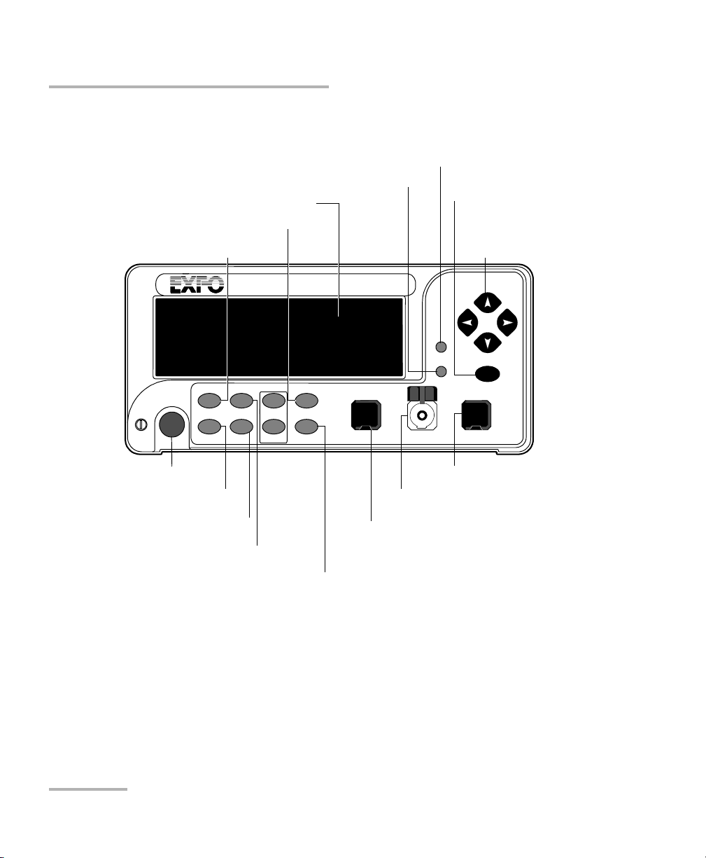
Output port
Offset mode access
Reference mode access
Confirmation
button (Enter)
Absolute mode access
Wavelength control
Arrow buttons for
menu navigation and
parameter setting
Program menu access
Monitor port
(BM and DM models only)
On/off button
Display
Shutter control
Attenuation controls
Step
In Monitor Out
Input port
Setup menu access
Shutter
Front Panel
Front Panel
Note: Your FVA-3150 Variable Attenuator may differ slightly from the illustration
depending on the specific model of your unit.
2 FVA-3150
Page 9
Back Panel
Electro-Optical Engineering
465 Godin Avenue
Vanier QC G1M 3G7 Canada
R
GPIB IEEE 488.2
SH1, AH1, T6, L4, SR1, RL1, PP0, DC1, DT1, C0, E2
This device complies with part 15 of th e FCC rules. Operation is
subject to the following two conditions: (1) this device may not cause
harmful interference and (2) this devic e must accept any interference
received, including interference that may cause undesired operation.
Made in Canada
P/N
S/N
Ver.
Mfg.
date
QST-151F
Serial Port
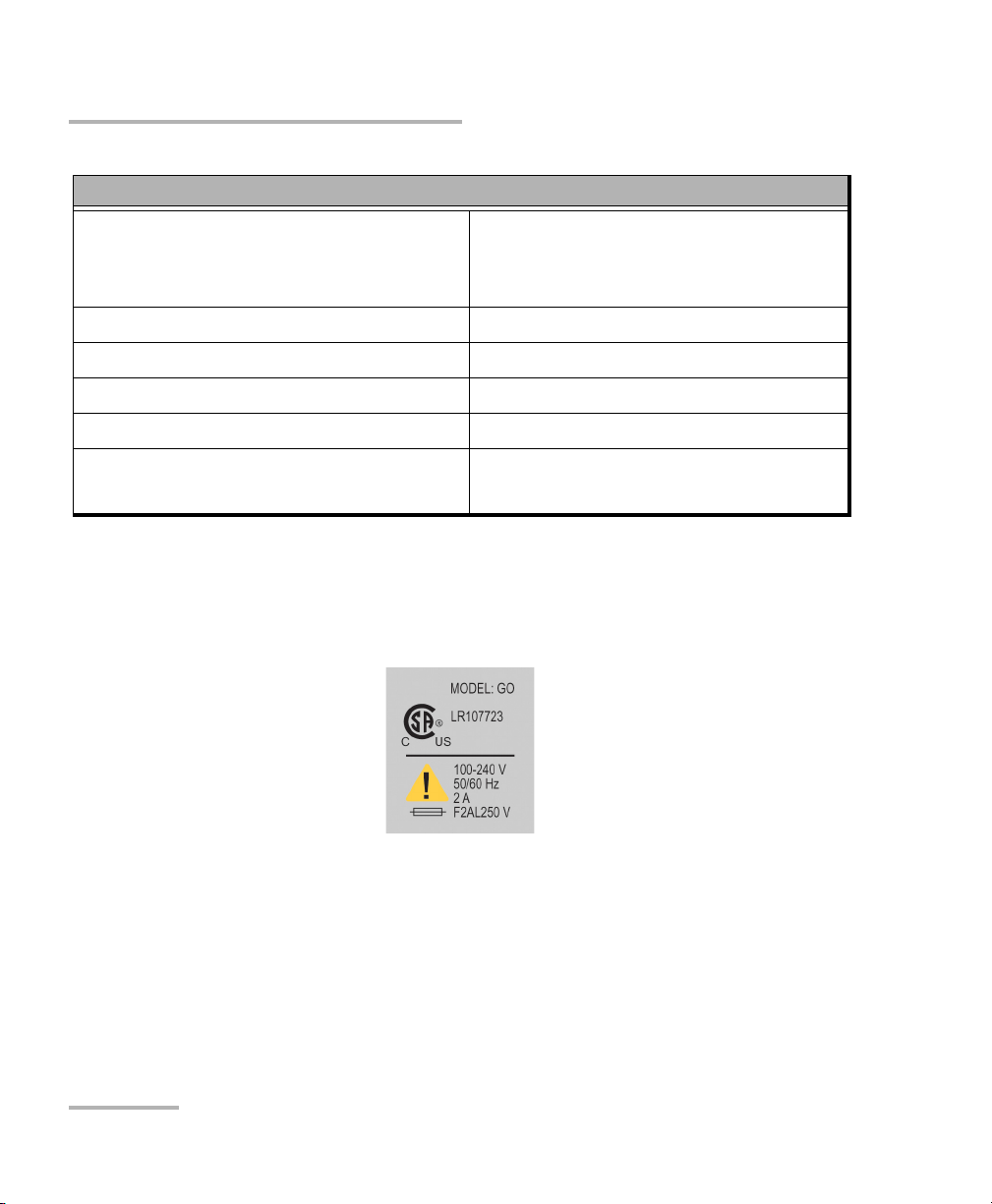
MODEL: GO
LR107723
100-240 V
50/60 Hz
2 A
F2AL250 V
C
US
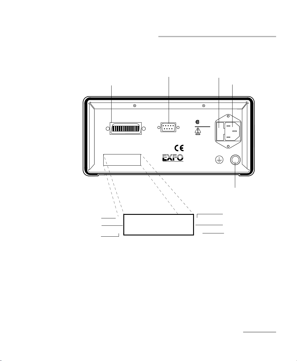
Serial port (RS-232 DTE)
Fuse holder
Power inlet
GPIB port
Ver.
Mfg.
date
S/N
FVA-3150-B-EI
12345-AB
A-1.0
J
ANUARY
2010
9/125 µ
M
1200 TO 1650
NM
P/N
Ground
Version number
Spectral range
Manufacturing date
Part number
Fiber type
Serial number
Introducing the FVA-3150 Variable Attenuator
Back Panel
Note: Your FVA-3150 Variable Attenuator may differ slightly from the illustration
depending on the specific model of your unit.
Variable Attenuator 3
Page 10

Introducing the FVA-3150 Variable Attenuator
Available Models
Available Models
According to the models you own, additional options are available. The
FVA-3150-CM, FVA-3150-BM, and FVA-3150-DM all come with a monitor
output, which ensures accurate power-level monitoring.
Typical Applications
The FVA-3150 Variable Attenuator is ideal for:
manufacturing and laboratory applications such as system
characterization
EDFA
component and system loss simulation
instrument calibration
power meter linearity measurement
spectral tuning
The FVA-3150 Variable Attenuator is particularly suitable to demanding
laboratory and manufacturing qualification applications.
4 FVA-3150
Page 11

Introducing the FVA-3150 Variable Attenuator
Main Concept
Main Concept
The significance of the attenuation value displayed by an optical attenuator
may differ from one manufacturer to another. At EXFO, for example, the
attenuation displayed by the FVA-3150 Variable Attenuator is the actual loss
or attenuation between the input and the output ports of the Variable
Attenuator, including the loss of its own internal connectors, after
performing a reference reading with a power meter.
IMPORTANT
The Variable Attenuator has been calibrated with a light source
connected to the input port and a power meter connected to the
output port. For optimum performance, do not interchange the
input and output connections.
Variable Attenuator 5
Page 12

Introducing the FVA-3150 Variable Attenuator
Conventions
Conventions
Before using the product described in this manual, you should understand
the following conventions:
WARNING
Indicates a potentially hazardous situation which, if not avoided,
could result in death or serious injury. Do not proceed unless you
understand and meet the required conditions.
CAUTION
Indicates a potentially hazardous situation which, if not avoided,
may result in minor or moderate injury. Do not proceed unless you
understand and meet the required conditions.
CAUTION
Indicates a potentially hazardous situation which, if not avoided,
may result in component damage. Do not proceed unless you
understand and meet the required conditions.
IMPORTANT
Refers to information about this product you should not overlook.
6 FVA-3150
Page 13

2 Safety Information
Laser Safety Information
WARNING
Do not install or terminate fibers while a light source is active.
Never look directly into a live fiber and ensure that your eyes are
protected at all times.
WARNING
Use of controls, adjustments and procedures for operation and
maintenance other than those specified herein may result in
hazardous radiation exposure or impair the protection provided by
this unit.
Variable Attenuator 7
Page 14

Safety Information
Electrical Safety Information
Electrical Safety Information
This unit uses an international safety standard three-wire power cable. This
cable serves as a ground when connected to an appropriate AC power
outlet.
Note: If you need to ensure that the unit is completely powered off, disconnect the
power cable.
WARNING
Insert the power cable plug into a power outlet with a
protective ground contact. Do not use an extension cord
without a protective conductor.
Before powering on the unit, connect all grounding terminals,
extension cords and devices to a protective ground via a ground
socket. Any interruption of the protective grounding is a
potential shock hazard and may cause personal injury.
Whenever the ground protection is impaired, do not use the
unit and secure it against any accidental operation.
Do not tamper with the protective ground terminal.
The color coding used in the electric cable depends on the cable. New
plugs should meet the local safety requirements and include:
adequate load-carrying capacity
ground connection
cable clamp
IMPORTANT
EXFO assumes no liability if you attempt to perform internal service
on this unit.
8 FVA-3150
Page 15

Safety Information
Electrical Safety Information
WARNING
Use this unit indoors only.
Position the unit so that the air can circulate freely around it.
Operation of any electrical instrument around flammable gases
or fumes constitutes a major safety hazard.
Do not remove unit covers during operation.
To avoid electrical shock, do not operate the unit if any part of
the outer surface (covers, panels, etc.) is damaged.
Only authorized personnel should carry out adjustments,
maintenance or repair of opened units under voltage. A person
qualified in first aid must also be present. Do not replace any
components while power cable are connected.
Use only fuses with the required rated current and specified
type (IEC, 5 mm x 20 mm (0.197 in x 0.787 in), fast-blow, 250 V,
2 A). Do not use repaired fuses or short-circuited fuse holders.
Capacitors inside the unit may be charged even if the unit has
been disconnected from its electrical supply.
Variable Attenuator 9
Page 16
Safety Information
Electrical Safety Information
Equipment Ratings
Tem pe rat ur e
Operation
Storage
Relative humidity
a
0 °C to 40 °C (32 °F to 104 °F)
-40 °C to 70 °C (-40 °F to 158 °F)
0 % to 80 % non-condensing
Maximum operation altitude 2000 m (6562 ft)
Pollution degree 2
Overvoltage category II
Power supply rating
b
100 V to 240 V (50 Hz/60 Hz)
maximum input power 2 A
a. Measured in 0 °C to 31 °C (32 °F to 87.8 °F) range, decreasing linearly to 50 % at 40 °C (104 °F).
b. Not exceeding
± 10 % of the nominal voltage.
The following label is located on the back panel of the unit:
10 FVA-3150
Page 17
3 Getting Started With Your
2
3
4
1
Variable Attenuator
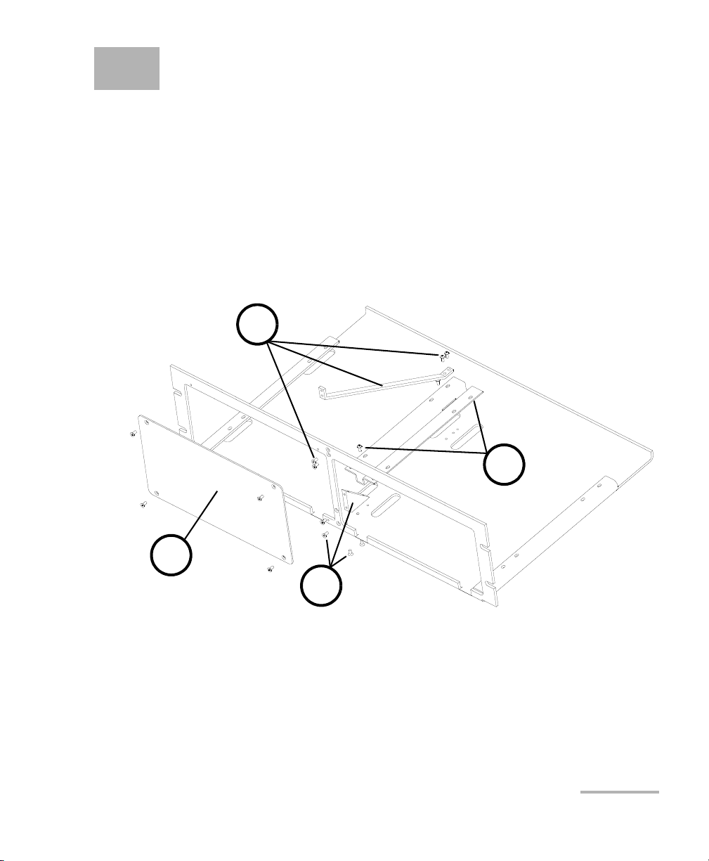
Installing your FVA-3150 Variable Attenuator in a Rackmount
You can place your FVA-3150 Variable Attenuator in a rackmount to
facilitate its usage.
To install the rackmount:
1. Fix the angle iron using four flat Phillips screws.
2. Fix the rackmount bracket to the frame using two round Phillips
screws.
3. Fix the rackmount stiffener using two flat Phillips screws (for the front
panel) and two round Phillips screws.
4. If your rackmount will contain only one unit, fix the rackmount cover
plate to the empty part of the frame using four flat Phillips screws.
Variable Attenuator 11
Page 18
Getting Started With Your Variable Attenuator
X
A
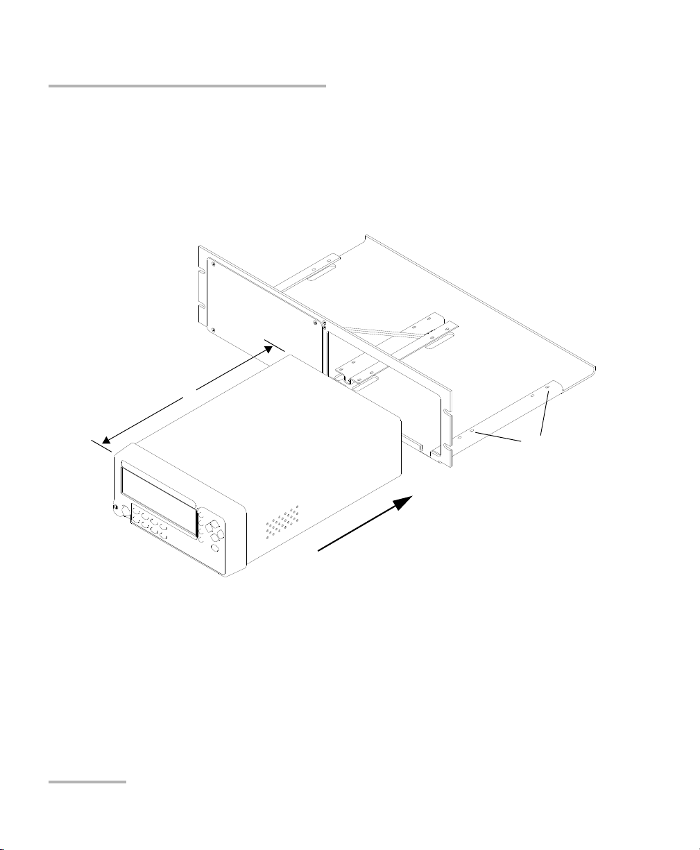
Installing your FVA-3150 Variable Attenuator in a Rackmount
To install your FVA-3150 Variable Attenuator in a rackmount:
1. Slide the benchtop unit into the rackmount and tighten it from
underneath using the four cover fixing screws.
If measurement X on the illustration exceeds 11.125 in., fix the unit into
the four holes identified as A. Otherwise, use the other four holes.
2. If a second benchtop is to be installed, remove the cover plate and
repeat step 1.
12 FVA-3150
Page 19

Getting Started With Your Variable Attenuator
Turning the Variable Attenuator On and Off
Turning the Variable Attenuator On and Off
When you turn on your unit:
it beeps twice
it performs a self-test
it enters the mode that was active at the last power-off (Absolute,
Offset, or Reference)
When you turn the unit off, the following items remain in read-only
memory:
current shutter state
current display mode
current attenuation setting
current wavelength
shortlisted wavelengths
each wavelength offsets
step size
remote-control settings
programmed attenuation routine settings
saved configurations
Note: The power cord is the most effective disconnecting device. To ensure that
the power is completely turned off, disconnect the power cord.
Variable Attenuator 13
Page 20
Getting Started With Your Variable Attenuator
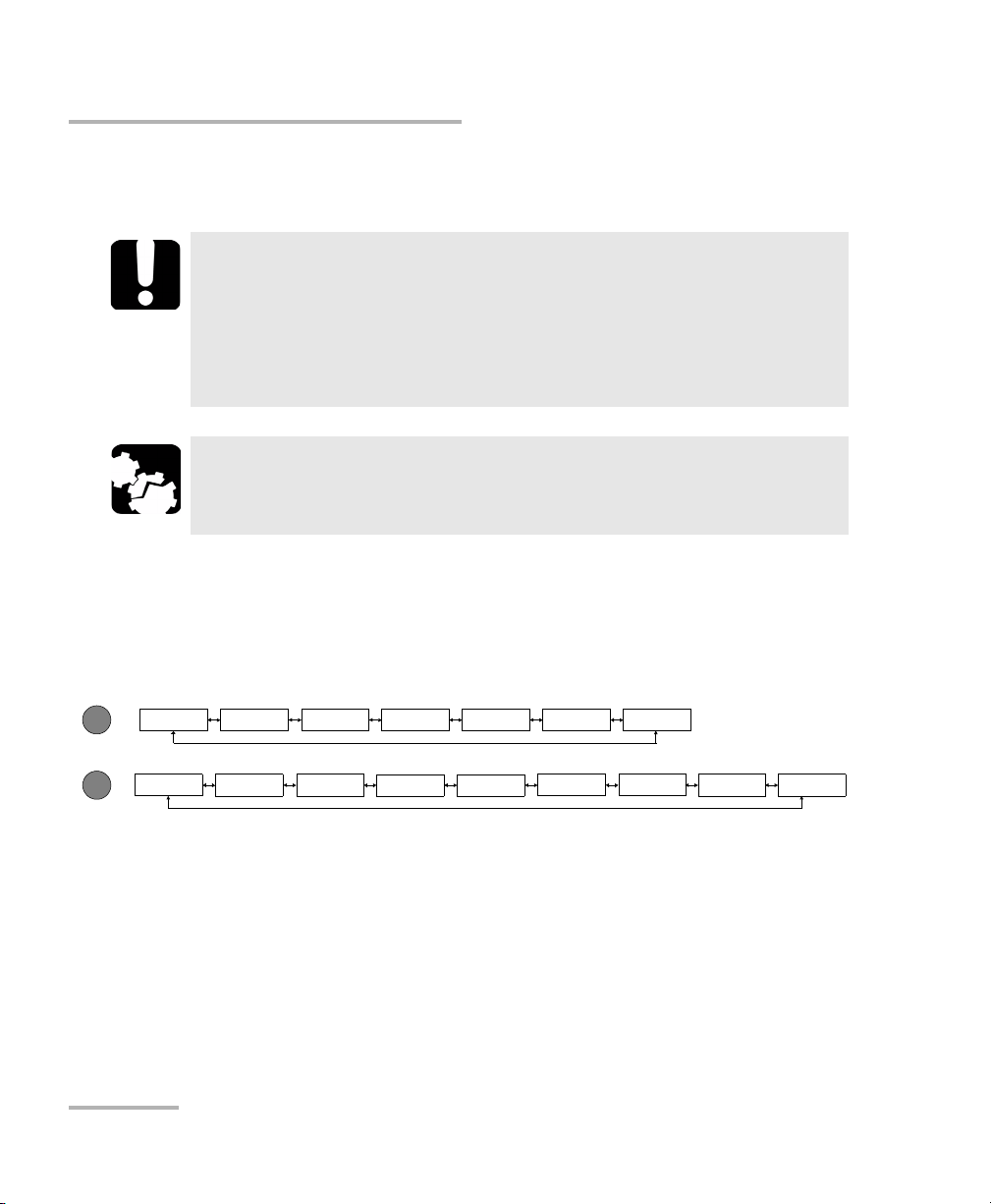
Program
Setup
Delay Duration
Step
ATT.
Start
Stop
Exit
Step Lambda
Offset
Dimmer GPIB-RS
Save
Recall Exit
Lockout
Accessing Menus
To turn the unit on and off:
Use the red button in the lower left corner of the front panel.
IMPORTANT
Some internal mechanisms can sometimes take a few seconds to
adjust, depending on the operation performed. While the Variable
Attenuator is performing internal adjustments (for example after
having changed the wavelength or the attenuation setting), no
buttons should be pressed while Program flashes on the display.
CAUTION
The Variable Attenuator should not be turned off while Program is
flashing in the lower left corner of the display.
Accessing Menus
The blue buttons to the right of the display give access to single-level
menus: Program and Setup. The following diagram shows the menus and
their items.
To move (in a loop) between the menu items:
Use the left/right arrows.
To exit a menu:
Press the button that gave access to the menu;
OR
Use the left/right arrows to move until EXIT is displayed, then press ENTER.
14 FVA-3150
Page 21

4 Setting Up Your Variable
Attenuator
Selecting the Display Intensity
Display intensity may be set to high or low. You can also turn off the display
without turning off the unit.
To select the display intensity:
1. Press the Setup button.
2. Use the left/right arrows to move until it displays DIMMER.
3. Press ENTER. The current dimmer state will start flashing.
4. Use the up/down arrows to modify the dimmer status: LO, HI, or OFF.
5. Press ENTER.
Note: Setting the dimmer to OFF turns off the display. Press any button to turn the
display back on.
6. To exit the Setup menu, press the Setup button.
Variable Attenuator 15
Page 22

Setting Up Your Variable Attenuator
Locking Control Key Access
Locking Control Key Access
To prevent unintended use of the FVA-3150 Variable Attenuator during
operation, you can lock the control keys (the blue buttons on the front
panel of the unit).
To lock the control key access:
1. Press the Setup button.
2. Use the left/right arrows until LOCKOUT is displayed.
3. Press ENTER.
The LOCKED message is briefly displayed, then the unit reverts to the
settings that were active before you entered the Setup menu. All control
keys are deactivated.
To unlock the keypad:
1. Press the Setup button.
2. Press ENTER.
The UNLOCKED message is briefly displayed. All control keys are
reactivated.
16 FVA-3150
Page 23

Setting Up Your Variable Attenuator
Managing the Wavelength Shortlist
Managing the Wavelength Shortlist
The FVA-3150 Variable Attenuator can test at many wavelengths. The
accepted wavelengths depend on the configuration of your unit. You can
store the wavelengths you use most often in a shortlist so you can quickly
access them. The shortlist includes up to 20 wavelengths.
Note: When switching to a new wavelength, the attenuator motor will reposition
itself to keep the current attenuation value for the new wavelength.
Refer to Technical Specifications on page 69 for more information on the
wavelength ranges that you can enter.
Variable Attenuator 17
Page 24
Setting Up Your Variable Attenuator
nm
Managing the Wavelength Shortlist
To add a wavelength to the shortlist:
1. Press the Setup button.
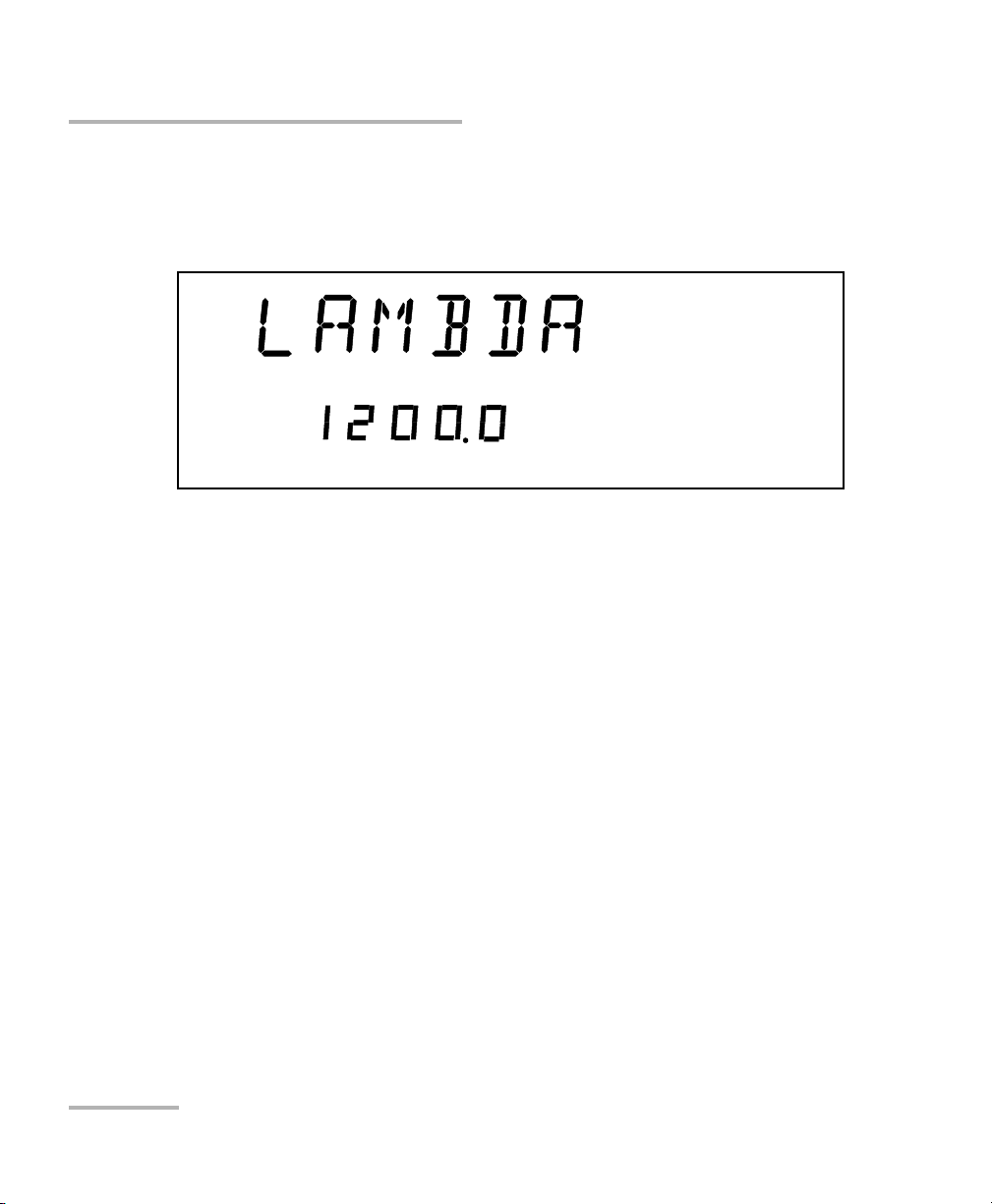
2. Use the left/right arrows to move until LAMBDA is displayed.
3. Use the up/down arrows to move until Add is displayed .
4. Press ENTER. A wavelength will be suggested and the first digit will
flash.
5. Use the up/down arrows to change the flashing digit and the left/right
arrows to activate the next digit.
6. Once all digits are set, press ENTER.
7. To exit the Setup menu, press the Setup button.
Note: If you are trying to enter a wavelength that is outside the wavelength range,
the Variable Attenuator will beep and reject the wavelength.
18 FVA-3150
Page 25

Setting Up Your Variable Attenuator
Managing the Wavelength Shortlist
To delete a wavelength from the shortlist:
1. Press the Setup button.
2. Press the left/right arrows until LAMBDA is displayed.
3. Use up/down arrows to move until the wavelength you want to delete
appears in the lower portion of the display.
4. Press ENTER. The wavelength will start flashing.
5. Set all the wavelength digits to zero. To do so, use the up/down arrows
to change the flashing digit and the left/right arrows to activate the next
digit.
6. Press ENTER.
7. To exit the Setup menu, press the Setup button.
To delete all wavelengths from the shortlist:
1. Press the Setup button.
2. Press the left/right arrows until LAMBDA is displayed.
3. Press the up/down arrows until DEL ALL appears in the lower portion
of the display.
4. Press ENTER.
Variable Attenuator 19
Page 26

Setting Up Your Variable Attenuator
Selecting the Attenuation
Selecting the Attenuation
The attenuation can be set using two methods:
By using the up and down arrows buttons, the attenuation is modified
one step (up or down) at a time.
By using the Attenuation button, you can quickly and precisely set the
attenuation to a specific value
The available step sizes are: 0.01, 0.02, 0.05, 0.1, 0.2, 0.5, 1, 2, 5, 10, 20, and
50 dB.
Note: Selecting a larger step size allows for faster attenuation scanning.
To change the step size:
1. Press the Setup button.
2. Press the left/right arrows until STEP is displayed.
3. Press ENTER. The current step size will start flashing.
4. Using the up/down arrows, select one of the available step sizes.
5. Press ENTER.
6. To exit the Setup menu, press the Setup button.
20 FVA-3150
Page 27
Setting Up Your Variable Attenuator
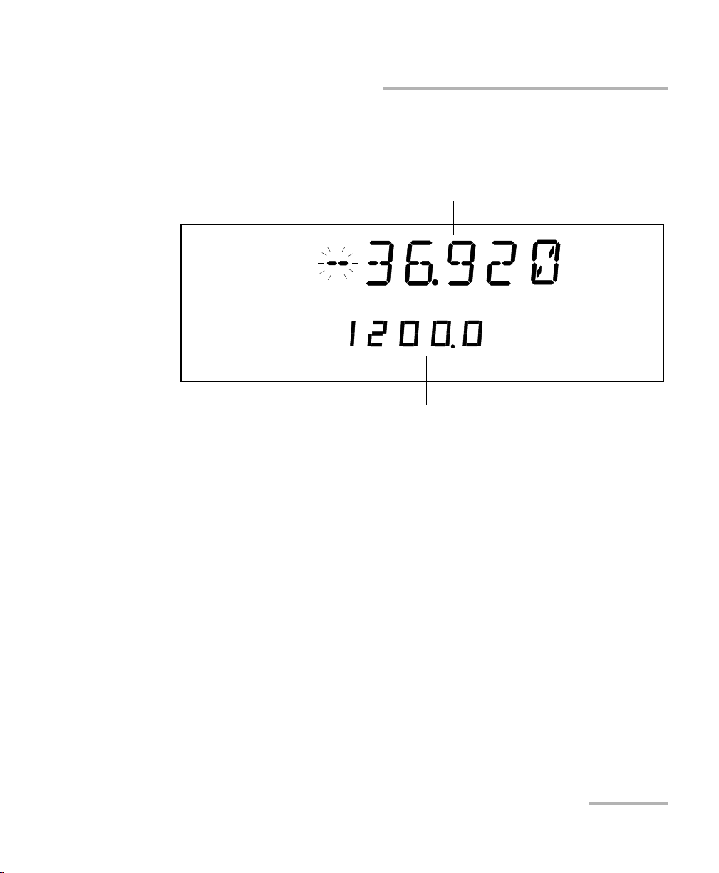
dB
Abs
nm
Attenuation setting
Current wavelength
Selecting the Attenuation
To enter a specific attenuation value:
1. Press the Attenuation button. The first segment of the attenuation
setting starts flashing.
2. Enter a new attenuation value. Use the up/down arrows to change the
flashing digit and the left/right arrows to activate the next digit.
Note: The difference with the current attenuation must be of at least 0.002 dB for
the new attenuation setting to be valid. For more information on the
variable attenuator optical resolution see Technical Specifications on
page 69.
3. Once you have entered all the segments, press ENTER.
Note: If you try to set an attenuation value that is outside the attenuation range,
the Variable Attenuator will default to the minimum or maximum setting.
The attenuation range (minimum and maximum possible attenuation) of
your FVA-3150 Variable Attenuator depends on the model you have at
hand. Although EXFO guarantees that the minimum insertion loss is below
a specified value, it may vary slightly from one wavelength to another and
from one variable attenuator to another.
Variable Attenuator 21
Page 28
Setting Up Your Variable Attenuator
VARIABLE ATTENUATOR
FVA-3150
Offset
ENTER
Abs Up Shutter
Ref
Down Attenuation
Program
Setup
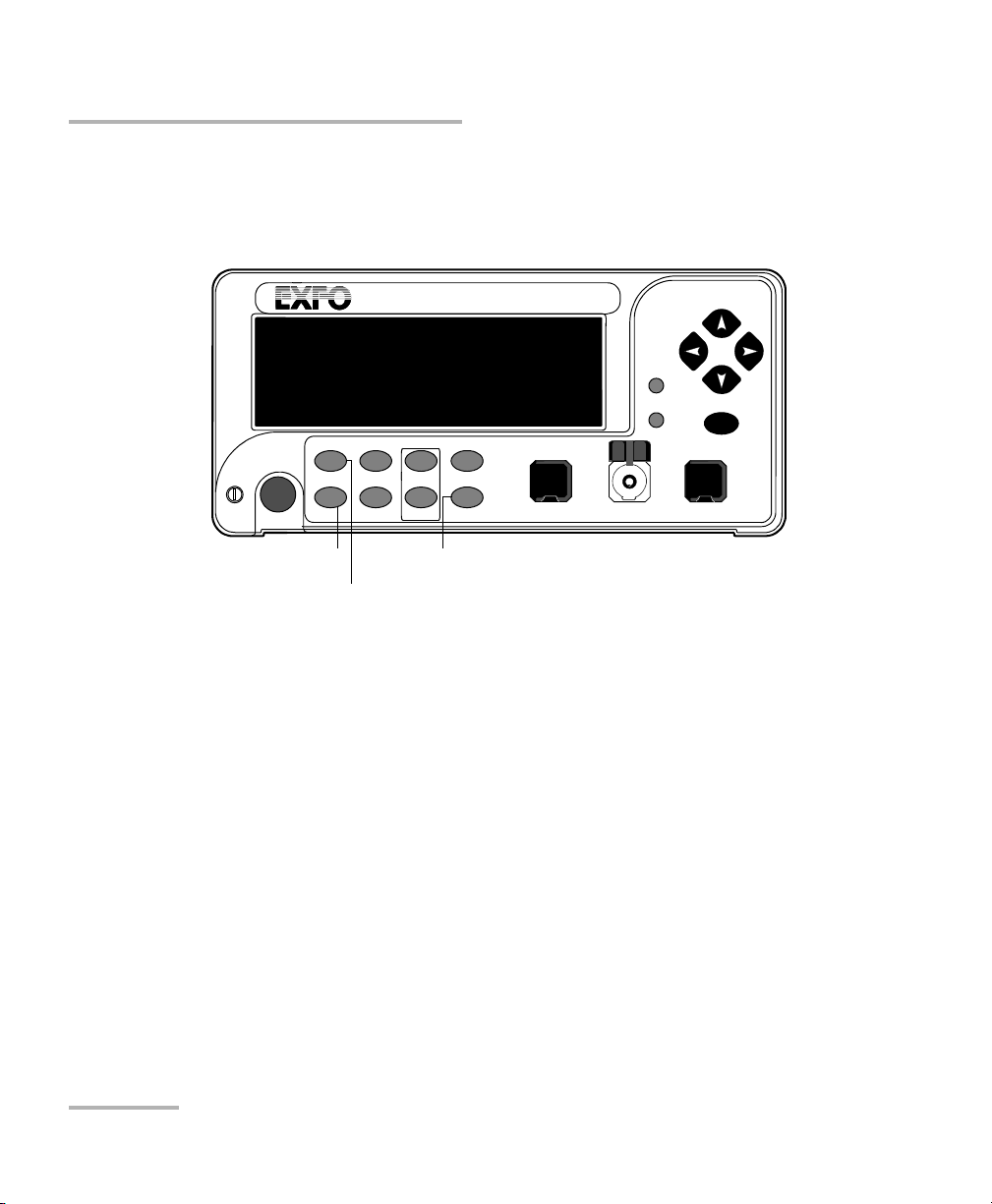
Absolute mode access
Step
In Monitor Out
Shutter
Wavelength control Attenuation
Selecting the Attenuation
To set the minimum attenuation:
1. Select a wavelength, by pressing until you reach the desired
wavelength.
2. Press the Abs button.
3. Press the Attenuation button and set an attenuation of 00.000 dB.
4. Press ENTER. The Variable Attenuator will default to the minimum
insertion loss.
22 FVA-3150
Page 29

Setting Up Your Variable Attenuator
Selecting the Attenuation
To set the maximum attenuation:
1. Select a wavelength by pressing until you reach the desired
wavelength.
2. Press the Abs button.
3. Press the Attenuation button and set an attenuation of -99.999 dB.
4. Press ENTER. The Variable Attenuator will default to the maximum
attenuation.
Variable Attenuator 23
Page 30

Setting Up Your Variable Attenuator
Selecting and Using an Attenuation Display Mode
Selecting and Using an Attenuation Display
Mode
Note: The total or absolute attenuation referred to in this manual is the actual
optical insertion loss between the input and output ports, including the
connectors.
The Variable Attenuator offers the following three attenuation display
modes:
Absolute attenuation mode
Offset attenuation mode
Reference attenuation mode
Display Mode Description
Absolute The displayed attenuation value takes into account both
the absolute value and the offset value.
Default mode upon initial activation.
Reference
(relative)
24 FVA-3150
The displayed attenuation value is the attenuation relative
to a defined reference value, which can be any value
within the unit’s attenuation range and may be selected as
the reference.
Page 31

Setting Up Your Variable Attenuator
Selecting and Using an Attenuation Display Mode
Display Mode Description
Offset (X + B) The displayed attenuation is the sum of two components:
X = physical attenuation introduced by the unit.
B = correction factor or offset; it may be used to
compensate for losses along the connecting fibers or
for losses displaying the attenuation as a power value.
Offset mode can be best explained by the following
example:
An optical light source with a power output of -14 dBm
at 1310 nm is connected to a variable attenuator.
Because of internal losses, the minimum insertion
loss at 1310 nm is approximately 2 dB. This means that
the maximum optical power available at the output
port of the attenuator is -16 dBm (-14 + -2). If we now
set an offset value of -14 dBm, the (large digits) will
display the optical power level at the output port of the
attenuator. Using the above setup (that is, light source,
variable attenuator, and an accurately determined
offset value), EXFO has created a precise variable light
source with a dynamic range of nearly 100 dB.
Note: You must define the appropriate B value for
the operating wavelength before enabling
X+B mode. A different B value may be
assigned to each wavelength in the
wavelength box.
Note: The active display mode is always indicated on the display.
Variable Attenuator 25
Page 32

Setting Up Your Variable Attenuator
dB
Abs
nm
Absolute attenuation
Wavelength
Selecting and Using an Attenuation Display Mode
To set Absolute attenuation mode:
Press the Abs button at any time to enable Absolute mode.
In Offset mode, the offset value is always displayed in the lower portion of
the display while the upper portion (large digits) displays the sum of two
values.
Before enabling the Offset mode, it is necessary to define the appropriate
offset value for the operating wavelength. A different offset value can be
associated with each wavelength in the shortlist.
26 FVA-3150
Page 33

Setting Up Your Variable Attenuator
dBm
Current offset value for
the selected wavelength
Selecting and Using an Attenuation Display Mode
To define an offset value for a specific wavelength:
1. Set the Variable Attenuator to the appropriate wavelength.
2. Select Setup.
3. Press the left/right arrows until OFFSET is displayed.
4. Press ENTER. The first segment of the current offset value will start
flashing.
5. Enter a new offset. Use the up/down arrows to change the flashing digit
and the left/right arrows to activate the next digit.
Note: Offset values between -99.999 and 99.999 may be entered. Use dB when
the offset represents loss and dBm when the offset represents power.
6. Once all the segments have been entered, press ENTER.
7. To exit the Setup menu, press the Setup button.
Variable Attenuator 27
Page 34

Setting Up Your Variable Attenuator
Offset
dB
dB
Offset attenuation
(actual attenuation is -6.00 dB)
Offset value for the
current wavelength
Selecting and Using an Attenuation Display Mode
To use the offset mode:
1. Ensure that the display is in Absolute mode (select Abs).
2. Select the appropriate wavelength by pressing until you reach the
desired wavelength.
3. If necessary, set an offset value.
4. Select Offset. The display will switch to Offset mode.
Note: The offset value can be modified while Offset mode is active.
28 FVA-3150
Page 35

Setting Up Your Variable Attenuator
dB
Ref
dB
Relative attenuation
Absolute attenuation
Selecting and Using an Attenuation Display Mode
Any value within the attenuation range may be selected as the reference.
When Reference mode is enabled (by selecting Ref):
the current absolute attenuation setting becomes the reference value
and appears in the lower portion of the display; and
0.000 dB (relative attenuation) is displayed in the upper portion of the
display.
If the attenuation is increased by 1.0 dB, the upper digits (relative
attenuation) will display -1.000 dB and the lower digits (absolute
attenuation) will indicate -17.450 dB.
Variable Attenuator 29
Page 36

Setting Up Your Variable Attenuator
VARIABLE ATTENUATOR
FVA-3150
Offset
ENTER
Abs Up Shutter
Ref
Down Attenuation
Program
Setup
Reference mode access
Absolute mode access
Step
In Monitor Out
Shutter
Selecting and Using an Attenuation Display Mode
To use the Reference mode:
1. Ensure that the display is in Absolute mode (select Abs).
2. Select the appropriate wavelength.
3. Set the attenuation to the desired reference value.
4. Press the Ref. button.The display will switch to Reference mode.
Note: Pressing Ref with the Reference mode already active will reset the
reference value to the current absolute attenuation setting.
30 FVA-3150
Page 37

Setting Up Your Variable Attenuator
Saving and Recalling a Configuration
Saving and Recalling a Configuration
Once the Variable Attenuator has been customized for a specific
application or user, it is possible to save the configuration. Saved
parameters are:
current wavelength and attenuation
display mode
step size
shortlisted wavelengths
each wavelength offset
programmed attenuation routine settings
Up to ten configurations can be saved and recalled.
Variable Attenuator 31
Page 38

Setting Up Your Variable Attenuator
Configuration number
Saving and Recalling a Configuration
To save a configuration:
1. Customize the Variable Attenuator as required.
2. Press the Setup button.
3. Press the left/right arrows until SAVE is displayed.
4. Press ENTER. The configuration number will start flashing.
5. Press the up/down arrows to modify the configuration number.
6. Press ENTER.
7. Press the Setup button to exit the menu.
Once you have saved a configuration (see Saving and Recalling a
Configuration on page 31), you can recall it at any time.
32 FVA-3150
Page 39

Setting Up Your Variable Attenuator
Configuration number
Saving and Recalling a Configuration
To recall a configuration:
1. Press the Setup button.
2. Press the left/right arrows until RECALL is displayed.
3. Press ENTER. The configuration number (bottom of the screen) will
start flashing.
4. Use the up/down arrows to select the number of the configuration you
want to recall.
5. Press ENTER.
6. To ex it th e Set up menu, press the Setup button.
Variable Attenuator 33
Page 40

Page 41

5 Operating Your Variable
Attenuator
Cleaning and Connecting Optical Fibers
IMPORTANT
To ensure maximum power and to avoid erroneous readings:
Always inspect fiber ends and make sure that they are clean as
explained below before inserting them into the port. EXFO is
not responsible for damage or errors caused by bad fiber
cleaning or handling.
Ensure that your patchcord has appropriate connectors. Joining
mismatched connectors will damage the ferrules.
To connect the fiber-optic cable to the port:
1. Inspect the fiber using a fiber inspection microscope. If the fiber is
clean, proceed to connecting it to the port. If the fiber is dirty, clean it as
explained below.
2. Clean the fiber ends as follows:
2a. Gently wipe the fiber end with a lint-free swab dipped in isopropyl
alcohol.
2b. Use compressed air to dry completely.
2c. Visually inspect the fiber end to ensure its cleanliness.
Variable Attenuator 35
Page 42

Operating Your Variable Attenuator
Cleaning and Connecting Optical Fibers
3. Carefully align the connector and port to prevent the fiber end from
touching the outside of the port or rubbing against other surfaces.
If your connector features a key, ensure that it is fully fitted into the
port’s corresponding notch.
4. Push the connector in so that the fiber-optic cable is firmly in place,
thus ensuring adequate contact.
If your connector features a screwsleeve, tighten the connector
enough to firmly maintain the fiber in place. Do not overtighten, as this
will damage the fiber and the port.
Note: If your fiber-optic cable is not properly aligned and/or connected, you will
notice heavy loss and reflection.
36 FVA-3150
Page 43

Operating Your Variable Attenuator
Bare metal
(or blue border)
indicates UPC
option
Green border
indicates APC
option
2 3 4
Installing the EXFO Universal Interface (EUI)
Installing the EXFO Universal Interface (EUI)
The EUI fixed baseplate is available for connectors with angled (APC) or
non-angled (UPC) polishing. A green border around the baseplate
indicates that it is for APC-type connectors.
To install an EUI connector adapter onto the EUI baseplate:
1. Hold the EUI connector adapter so the dust cap opens downwards.
2. Close the dust cap in order to hold the connector adapter more firmly.
3. Insert the connector adapter into the baseplate.
4. While pushing firmly, turn the connector adapter clockwise on the
baseplate to lock it in place.
Variable Attenuator 37
Page 44

Operating Your Variable Attenuator
Performing an Attenuation Routine
Performing an Attenuation Routine
You can program the FVA-3150 Variable Attenuator to perform an
attenuation routine. Once the routine is started, the variable attenuator will
automatically increase or decrease the inserted attenuation (by steps),
return to the initial attenuation state, and perform the routine again until
you stop it. The following parameters may be set:
delay: the beginning of the attenuation routine may be delayed by up to
999 hours, 59 minutes and 59 seconds
duration: the variable attenuator can remain up to 999 hours,
59 minutes and 59 seconds at each attenuation step
number of steps: the attenuation routine may comprise up to 99 steps
attenuation difference between two steps: the difference in
attenuation between two steps may be up to 99.999 dB
Note: Once set, the routine parameters remain in memory until new ones are
entered.
The following example shows how parameters are set up, as well as how
an attenuation routine works.
If you start an attenuation routine with the following settings:
Delay: 5 minutes
Duration: 10 seconds
Number of steps: 3
Attenuation difference between each step: –1 dB, and
Initial attenuation state: –10 dB
the Variable Attenuator will:
Wait five minutes before starting the routine
Remain at –10 dB attenuation for 10 seconds (step 0)
38 FVA-3150
Page 45

Operating Your Variable Attenuator
Hours
Seconds
Minutes
Performing an Attenuation Routine
Switch to –11 dB attenuation for 10 seconds (step 1)
Switch to –12 dB attenuation for 10 seconds (step 2)
Switch to –13 dB attenuation for 10 seconds (step 3), and
Return to the initial attenuation state (-10 dB) for 10 seconds (step 0)
and repeat the routine until you stop it
To program the attenuation routine:
1. Press the Program button.
2. Press ENTER. The first digit will start flashing. Use the up/down arrows
to change the flashing digit and the left/right arrows to activate the next
digit.
Variable Attenuator 39
Page 46

Operating Your Variable Attenuator
Hours
Minutes
Seconds
Performing an Attenuation Routine
3. If you do not want the routine to be delayed, leave the delay
at 000.00.00.
4. Once the delay is set, press ENTER.
5. Select the duration (time for which the Variable Attenuator will remain
at each step). Press the right arrow.
6. Press ENTER. The first digit will start flashing. Use the up/down arrows
to change the flashing digit and the left/right arrows to activate the next
digit.
7. Once the duration is set, press ENTER.
8. Press the right arrow. You will see the following display.
40 FVA-3150
Page 47

Operating Your Variable Attenuator
dB
Performing an Attenuation Routine
9. Press ENTER. The first digit will start flashing. Use the up/down arrows
to change the flashing digit and the left/right arrows to activate the next
digit.
10. Once the number of steps is set, press ENTER.
11. Press the right arrow. To set the attenuation difference between the
steps.
12. Press ENTER. The first segment will start flashing. Use the up/down
arrows to change the flashing digit and the left/right arrows to activate
the next digit.
Note: Entering a negative value will increase the attenuation (in absolute value)
during the routine. Entering a positive value will decrease it.
13. Once the step size is set, press ENTER.
Note: The difference with the current attenuation must be of at least 0.002 dB for
the new attenuation step size to be valid.
14. Press the Program button to exit the menu.
Note: The initial attenuation state counts as a step.
Variable Attenuator 41
Page 48

Operating Your Variable Attenuator
VARIABLE ATTENUATOR
FVA-3150
Offset
ENTER
Abs Up Shutter
Ref
Down Attenuation
Program
Setup
Program menu access
Step
In Monitor Out
Shutter
Wavelength control
Performing an Attenuation Routine
To start a routine:
1. Set the wavelength by pressing until you reach the desired
wavelength.
2. Set the Variable Attenuator to the initial attenuation.
3. Press Program.
4. Press left/right ar rows until START is displayed.
5. Press ENTER. Program, in the lower left portion of the display,
indicates that an attenuation routine is in progress.
Note: During a program, if the attenuation reaches the limit of the attenuation
range, it will remain set at this value until the routine is completed.
Once you have started the routine, the display goes back to the current
attenuation mode display.
42 FVA-3150
Page 49

Operating Your Variable Attenuator
Performing an Attenuation Routine
To know... perform the following steps
how much time is
left in the delay
how much time is
left in the current
step
how many steps are
left in the current
routine
To stop the attenuation routine:
1. Press Program.
2. Press the left/right arrows until STOP is displayed.
3. Press ENTER.
The routine completes the current attenuation step, then stops (Program
disappears from the display).
Press Program
Press the left/right arrows until DELAY is displayed.
Press Program
Press the left/rigth arrows until DURATION is displayed.
Press Program
Press the left/rigth arrows until STEP is displayed.
Variable Attenuator 43
Page 50

Operating Your Variable Attenuator
VARIABLE ATTENUATOR
FVA-3150
Offset
ENTER
Abs Up Shutter
Ref
Down Attenuation
Program
Setup
Shutter control
Step
In Monitor Out
Shutter
Operating the Shutter
Operating the Shutter
The optical shutter is an electro-mechanical device which, when activated,
totally blocks light transmission.
To block light transmission:
Use the Shutter button to turn the shutter on or off. When the shutter is
activated, Shutter On appears in the lower right portion of the display.
CAUTION
Using the shutter continuously at a rate of one cycle per three
seconds may damage the instrument permanently or seriously
reduce its life cycle.
44 FVA-3150
Page 51

6 Controlling Your Variable
GPIB
setting
Attenuator Remotely
The FVA-3150 Variable Attenuator can be remotely controlled either by:
a GPIB interface (through a GPIB cable connected to the GPIB port), or
an RS-232 interface (through a serial cable connected to the serial
port)
The commands used in both protocols are the same and are described in
the following pages. When the Variable Attenuator is being remotely
controlled, Remote appears in the lower left corner of the display.
Note: If you have already designed a GPIB program to control an attenuator from
EXFO’s IQS Series (IQS-3100 or IQS-3150), you can reuse sections for the
FVA-3150.
Setting Up the Variable Attenuator for Remote Control
To remotely control the Variable Attenuator, you need to set a GPIB address
or activate the RS-232 port from the FVA-3150 front panel.
To set up the Variable Attenuator for remote:
1. Press Setup.
2. Use the left/right arrows to select GPIB-RS.
Variable Attenuator 45
Page 52

Controlling Your Variable Attenuator Remotely
GPIB
setting
GPIB address
RS-232 setting
Setting Up the Variable Attenuator for Remote Control
To select remote command mode:
1. If you have select GPIB-RS as a command mode, you only need to set
the address.
2. If you want to select the RS-232 mode, press ENTER.
3. Use the up and down arrows to reach RS-232 (before setting GPIB
address 1 or GPIB address 30).
4. Press ENTER.
5. To exit the Setup menu, press the Setup button.
46 FVA-3150
Page 53

Controlling Your Variable Attenuator Remotely
GPIB Setting
GPIB address
Setting Up the Variable Attenuator for Remote Control
To select a GPIB address:
1. Once you selected GPIB as a command mode, you can set the GPIB
address you want.
2. Press ENTER. The bottom part of the displays will start flashing.
3. Using the up and down arrows, select the GPIB address you want.
Variable Attenuator 47
Page 54

Controlling Your Variable Attenuator Remotely
Communication Parameters
Communication Parameters
Note: EOS means End of String. EOI means End or Identify.
For GPIB Communication
Terminate Read on EOS Yes
Set EOI with EOS on Writes Yes
Type of comparison on EOS 8-bits
EOS byte 0Ah
Sends EOI at end of Writes Yes
GPIB primary address 10
GPIB secondary address None
For RS-232 Communication
EOS bytes 0Ah
Baud rate 9600 bps
Parity None
Data bits 8 bits
Stop bits 1 bits
Flow control None
Activation see Setting Up the Variable Attenuator for
Remote Control on page 45
48 FVA-3150
Page 55

Controlling Your Variable Attenuator Remotely
Standard Status Data Structure
Standard Status Data Structure
The following page illustrates the four common status and enable registers
as defined by IEEE 488.2. This diagram is a useful aid in understanding the
general commands and how a service request (SRQ) is generated. The
four registers are:
Standard Event Status Register (ESR)
Standard Event Status Enable Register (ESE)
Status Byte Register (STB)
Service Request Enable Register (SRE)
Bit ESR ESE STB SRE
0 Operation
Complete
Operation
Complete
Source Status Source Status
1 Request Control Request Control
2 Query Error Query Error Error Bit
3 Device-
Dependent Error
DeviceDependent Error
Questionable
Status
Questionable
Status
4 Execution Error Execution Error Event Status Bit Event Status Bit
5 Command Error Command Error Message
Available
6 User Request User Request Master Summary
Status
Message
Available
Request
Service/Master
Summary Status
7 Power On Power On Operation Status Operation Status
Variable Attenuator 49
Page 56

Controlling Your Variable Attenuator Remotely
&
&
&
&
&
&
&
&
OR
Standard Event Status
Register (ESR)
Standard Event
Status Enable
Register (ESE)
&
&
&
&
&
&
&
OR
Status Byte
Register
(STB)
Service Request Enable
Register (SRE)
7
6
5 4 3 2 1 0
7 6 5 4 3 2 1 0
7 6 5 4 3 2 1 0
7 5 4 3 2 1 0
ESB MAV EB
ESB MAV
RQS
6
MSS
Service Request
Generation
{
{
Output Queue not Empty
read by serial poll
read by *STB?
PON
OPC
URQ
RQCQYE
DDE
EXECME
PON
OPC
URQ
RQCQYE
DDE
EXECME
Standard Status Data Structure
50 FVA-3150
Page 57

Controlling Your Variable Attenuator Remotely
Command Structure
An SRQ is forced when a bit is set in the STB and at the same time the
corresponding SRE bit is set. When the SRQ is generated, the RQS bit is set
to 1 and remains set until read by a serial poll. Once the RQS is read, it
returns to 0.
Command Structure
The GPIB and RS-232 commands follow the guidelines determined by the
Standard Commands for Programmable Interface (SCPI) consortium.
For example, the command syntax
OUTP[:STAT]<wsp><boolean>
is used to control the FVA-3150 shutter.
In this particular example:
OUTP identifies that the command is a part of the OUTPut subset
of commands;
STAT is a keyword that defines the function of the command;
[ ] indicates that a keyword or a parameter is optional;
<wsp> indicates that a space is required and
<boolean> is the command parameter.
All keywords must be UPPERCASE characters separated by a colon.
A typical command would be
OUTP:STAT 1
This command instructs the Variable Attenuator to optically open the
shutter.
Note: It is recommended to retrieve the response immediately after each query.
Variable Attenuator 51
Page 58

Controlling Your Variable Attenuator Remotely
<Error number>
,
“
<Error description>
;
<Device dependent
“
information>
Error Messages
Error Messages
System and device-specific errors are managed by the FVA-3150 Variable
Attenuator. The generic format for error messages is illustrated in the
following figure.
As shown in the above figure, the message contains three parts: the error
number, error description, and device-dependent information. All error
messages are stacked in a FIFO buffer. When there is at least one message
in the buffer, bit 2 of the Status Byte Register is set to 1. Use the SYST:ERR?,
ERR?, or LERR? command to read the most recent message. The error
message buffer is initialized when starting the Variable Attenuator, when
executing the *CLS command, or by reading the last message stored in the
buffer.
52 FVA-3150
Page 59

Controlling Your Variable Attenuator Remotely
SCPI Management Errors (System Errors)
SCPI Management Errors (System Errors)
Error
Number
Description Probable Cause
–100 “Command Error.” An error occurred while validating a
command.
–101 “Undefined Header.” Unknown command.
–102 “Missing Parameter.” A command parameter is missing.
–103 “Parameter Not Allowed.” An extra parameter is present.
–104 “Data Type Error.” Invalid parameter format.
–200 “Execution Error.” An error occurred while executing a
command.
–300 “Device Dependent Error.” A command has taken longer than
expected to complete execution.
–300 “Invalid Attenuation.” A command has attempted to set the
internal attenuation to an invalid value.
–300 “Invalid Offset.” The reference value parameter entered
is out of range.
–300 “Program Running.” A command that will halt the currently
running program has been received, or
an attempt has been made to override
a program setting.
–300 “Invalid Wavelength.” The entered wavelength parameter is
out of range.
–300 “Invalid Delay Time.” The entered delay parameter is out of
range.
–300 “Invalid Duration Time.” The entered duration time parameter is
out of range.
Variable Attenuator 53
Page 60

Controlling Your Variable Attenuator Remotely
1234 5
6789
RS-232 Connector Pinout
Error
Number
Description Probable Cause
–300 “Invalid Program Step.” The entered program step parameter is
out of range.
–300 “Invalid Program
Attenuation.”
The entered program attenuation
parameter is out of range.
–300 “Invalid CAL Factor.” The entered calibration factor
parameter is out of range.
–400 “Query Error.” An error occurred while accessing the
output queue.
–500 “System Error.” System is out of memory.
RS-232 Connector Pinout
The RS-232 connector (serial port) at the back of the Variable Attenuator
uses a DTE pinout configuration.
Pin Description Direction
2 Receive (Rx) Input
3 Transmit (Tx) Output
5 Signal ground (Gnd) —
54 FVA-3150
Page 61

7 Maintenance
To help ensure long, trouble-free operation:
Always inspect fiber-optic connectors before using them and clean
them if necessary.
Keep the unit free of dust.
Clean the unit casing and front panel with a cloth slightly dampened
with water.
Store unit at room temperature in a clean and dry area. Keep the unit
out of direct sunlight.
Avoid high humidity or significant temperature fluctuations.
Avoid unnecessary shocks and vibrations.
If any liquids are spilled on or into the unit, turn off the power
immediately, disconnect from any external power source, remove the
batteries and let the unit dry completely.
Use of controls, adjustments, and procedures for operation and
maintenance other than those specified herein may result in
hazardous radiation exposure.
WARNING
Variable Attenuator 55
Page 62

Maintenance
Push
Tur n
Pull
3
4
5
Cleaning EUI Connectors
Cleaning EUI Connectors
Regular cleaning of EUI connectors will help maintain optimum
performance. There is no need to disassemble the unit.
If any damage occurs to internal connectors, the module casing will
have to be opened and a new calibration will be required.
To clean EUI connectors:
1. Remove the EUI from the instrument to expose the connector
baseplate and ferrule.
IMPORTANT
2. Moisten a 2.5 mm cleaning tip with one drop of isopropyl alcohol
(alcohol may leave traces if used abundantly).
3. Slowly insert the cleaning tip into the EUI adapter until it comes out on
the other side (a slow clockwise rotating movement may help).
4. Gently turn the cleaning tip one full turn, then continue to turn as you
withdraw it.
56 FVA-3150
Page 63

Cleaning EUI Connectors
5. Repeat steps 3 to 4 with a dry cleaning tip.
Note: Make sure you don’t touch the soft end of the cleaning tip.
6. Clean the ferrule in the connector port as follows:
6a. Deposit one drop of isopropyl alcohol on a lint-free wiping cloth.
IMPORTANT
Isopropyl alcohol may leave residues if used abundantly or left to
evaporate (about 10 seconds).
Avoid contact between the tip of the bottle and the wiping cloth,
and dry the surface quickly.
6b. Gently wipe the connector and ferrule.
6c. With a dry lint-free wiping cloth, gently wipe the same surfaces to
ensure that the connector and ferrule are perfectly dry.
6d. Verify connector surface with a portable fiber-optic microscope
(for example, EXFO’s FOMS) or fiber inspection probe (for
example, EXFO’s FIP).
Maintenance
WARNING
Verifying the surface of the connector WHILE THE UNIT IS ACTIVE
WILL result in permanent eye damage.
7. Put the EUI back onto the instrument (push and turn clockwise).
8. Throw out cleaning tips and wiping cloths after one use.
Variable Attenuator 57
Page 64

Maintenance
Cleaning Detector Ports
Cleaning Detector Ports
Regular cleaning of detectors will help maintain measurement accuracy.
Always cover detectors with protective caps when unit is not in use.
To clean detector ports:
1. Remove the protective cap and adapter (FOA) from the detector.
2. If the detector is dusty, blow dry with compressed air.
3. Being careful not to touch the soft end of the swab, moisten a cleaning
tip with only one drop of isopropyl alcohol.
Alcohol may leave traces if used abundantly. Do not use bottles that
distribute too much alcohol at a time.
IMPORTANT
IMPORTANT
4. While applying light pressure (to avoid breaking the detector window),
gently rotate the cleaning tip on the detector window.
5. Repeat step 4 with a dry cleaning tip or blow dry with compressed air.
6. Discard the cleaning tips after one use.
58 FVA-3150
Page 65

Maintenance
Recalibrating the Unit
Recalibrating the Unit
Manufacturing and service center calibrations are based on the
ISO/IEC 17025 Standard, which states that calibration documents must not
contain a recommended calibration interval, unless this has been
previously agreed upon with the customer.
Validity of specifications depends on operating conditions. For example,
the calibration validity period can be longer or shorter depending on the
intensity of use, environmental conditions and unit maintenance. You
should determine the adequate calibration interval for your unit according
to your accuracy requirements.
Under normal use, EXFO recommends calibrating your unit every year.
Variable Attenuator 59
Page 66

Maintenance
Recycling and Disposal (Applies to European Union Only)
Recycling and Disposal
(Applies to European Union Only)
Recycle or dispose of your product (including electric and
electronic accessories) properly, in accordance with local
regulations. Do not dispose of it in ordinary garbage receptacles.
This equipment was sold after August 13, 2005 (as identified by
the black rectangle).
Unless otherwise noted in a separate agreement between EXFO and a
customer, distributor, or commercial partner, EXFO will cover costs
related to the collection, treatment, recovery, and disposal of
end-of-lifecycle waste generated by electronic equipment introduced
after August 13, 2005 to an European Union member state with
legislation regarding Directive 2002/96/EC.
Except for reasons of safety or environmental benefit, equipment
manufactured by EXFO, under its brand name, is generally designed to
facilitate dismantling and reclamation.
For complete recycling/disposal procedures and contact information, visit
the EXFO Web site at www.exfo.com/recycle.
60 FVA-3150
Page 67

8 Troubleshooting
Ver.
Mfg.
date
P/N
S/N
Made in Canada QST442B
465 Godin Avenue
Vanier (Quebec) G1M 3G7 CANADA
**************** A
January 2020
542392-3D
Fiber
Connector code
FVA-3150-XX-XX
Contacting the Technical Support Group
To obtain after-sales service or technical support for this product, contact
EXFO at one of the following numbers. The Technical Support Group is
available to take your calls from Monday to Friday, 8:00 a.m. to 7:00 p.m.
(Eastern Time in North America).
For detailed information about technical support, visit the EXFO Web site at
www.exfo.com.
Technical Support Group
400 Godin Avenue
Quebec (Quebec) G1M 2K2
CANADA
To accelerate the process, please have information such as the name and
the serial number (see the product identification label—an example is
shown below), as well as a description of your problem, close at hand.
1 866 683-0155 (USA and Canada)
Tel.: 1 418 683-5498
Fax: 1 418 683-9224
support@exfo.com
Variable Attenuator 61
Page 68

Troubleshooting
Transportation
Transportation
Maintain a temperature range within specifications when transporting the
unit. Transportation damage can occur from improper handling. The
following steps are recommended to minimize the possibility of damage:
Pack the unit in its original packing material when shipping.
Avoid high humidity or large temperature fluctuations.
Keep the unit out of direct sunlight.
Avoid unnecessary shocks and vibrations.
62 FVA-3150
Page 69

9 Warranty
General Information
EXFO Inc. (EXFO) warrants this equipment against defects in material and
workmanship for a period oftwo years from the date of original shipment.
EXFO also warrants that this equipment will meet applicable specifications
under normal use.
During the warranty period, EXFO will, at its discretion, repair, replace,
or issue credit for any defective product, as well as verify and adjust the
product free of charge should the equipment need to be repaired or if the
original calibration is erroneous. If the equipment is sent back for
verification of calibration during the warranty period and found to meet all
published specifications, EXFO will charge standard calibration fees.
The warranty can become null and void if:
unit has been tampered with, repaired, or worked upon by
unauthorized individuals or non-EXFO personnel.
warranty sticker has been removed.
IMPORTANT
case screws, other than those specified in this guide, have been
removed.
case has been opened, other than as explained in this guide.
unit serial number has been altered, erased, or removed.
unit has been misused, neglected, or damaged by accident.
THIS WARRANTY IS IN LIEU OF ALL OTHER WARRANTIES EXPRESSED,
IMPLIED, OR STATUTORY, INCLUDING, BUT NOT LIMITED TO, THE
IMPLIED WARRANTIES OF MERCHANTABILITY AND FITNESS FOR A
PARTICULAR PURPOSE. IN NO EVENT SHALL EXFO BE LIABLE FOR
SPECIAL, INCIDENTAL, OR CONSEQUENTIAL DAMAGES.
Variable Attenuator 63
Page 70

Warranty
Liability
Liability
EXFO shall not be liable for damages resulting from the use of the product,
nor shall be responsible for any failure in the performance of other items to
which the product is connected or the operation of any system of which
the product may be a part.
EXFO shall not be liable for damages resulting from improper usage or
unauthorized modification of the product, its accompanying accessories
and software.
64 FVA-3150
Page 71

Warranty
Exclusions
EXFO reserves the right to make changes in the design or construction of
any of its products at any time without incurring obligation to make any
changes whatsoever on units purchased. Accessories, including but not
limited to fuses, pilot lamps, batteries and universal interfaces (EUI) used
with EXFO products are not covered by this warranty.
This warranty excludes failure resulting from: improper use or installation,
normal wear and tear, accident, abuse, neglect, fire, water, lightning or
other acts of nature, causes external to the product or other factors beyond
the control of EXFO.
IMPORTANT
EXFO will charge a fee for replacing optical connectors that were
damaged due to misuse or bad cleaning.
Certification
Exclusions
EXFO certifies that this equipment met its published specifications at the
time of shipment from the factory.
Variable Attenuator 65
Page 72

Warranty
Service and Repairs
Service and Repairs
EXFO commits to providing product service and repair for five years
following the date of purchase.
To send any equipment for service or repair:
1. Call one of EXFO’s authorized service centers (see EXFO Service
2. If equipment must be returned to EXFO or an authorized service
3. If possible, back up your data before sending the unit for repair.
4. Pack the equipment in its original shipping material. Be sure to include
5. Return the equipment, prepaid, to the address given to you by support
Centers Worldwide on page 67). Support personnel will determine if
the equipment requires service, repair, or calibration.
center, support personnel will issue a Return Merchandise
Authorization (RMA) number and provide an address for return.
a statement or report fully detailing the defect and the conditions under
which it was observed.
personnel. Be sure to write the RMA number on the shipping slip. EXFO
will refuse and return any package that does not bear an RMA number.
Note: A test setup fee will apply to any returned unit that, after test, is found to
meet the applicable specifications.
After repair, the equipment will be returned with a repair report. If the
equipment is not under warranty, you will be invoiced for the cost
appearing on this report. EXFO will pay return-to-customer shipping costs
for equipment under warranty. Shipping insurance is at your expense.
Routine recalibration is not included in any of the warranty plans. Since
calibrations/verifications are not covered by the basic or extended
warranties, you may elect to purchase FlexCare Calibration/Verification
Packages for a definite period of time. Contact an authorized service center
(see EXFO Service Centers Worldwide on page 67).
66 FVA-3150
Page 73

Warranty
EXFO Service Centers Worldwide
EXFO Service Centers Worldwide
If your product requires servicing, contact your nearest authorized service
center.
EXFO Headquarters Service Center
400 Godin Avenue
Quebec (Quebec) G1M 2K2
CANADA
EXFO Europe Service Center
Omega Enterprise Park, Electron Way
Chandlers Ford, Hampshire S053 4SE
ENGLAND
EXFO Telecom Equipment
(Shenzhen) Ltd.
3rd Floor, Building 10,
Yu Sheng Industrial Park (Gu Shu
Crossing), No. 467,
National Highway 107,
Xixiang, Bao An District,
Shenzhen, China, 518126
1 866 683-0155 (USA and Canada)
Tel.: 1 418 683-5498
Fax: 1 418 683-9224
quebec.service@exfo.com
Tel.: +44 2380 246810
Fax: +44 2380 246801
europe.service@exfo.com
Tel: +86 (755) 2955 3100
Fax: +86 (755) 2955 3101
beijing.service@exfo.com
Variable Attenuator 67
Page 74

Page 75

A Technical Specifications
SPECIFICATIONS
a
SINGLEMODE CONFIGURATIONS
Description without monitor port with monitor port
Models FVA-3150-B FVA-3150-BM
Fiber type (μm) 9/125 9/125
Wavelength range (nm) 1250 to 1650 1250 to 1650
Maximum attenuation (dB)
b
*65 *65
Insertion loss
c, d
Typical (dB) 1.0 1.5
Maximum (dB) 1.5 2.2
Attenuation setting resolution, typical (dB) ±0.002 ±0.002
Attenuation linearity (dB)
e
±0.1 ±0.1
Attenuation repetability (dB), 2 m
f
±0.01 ±0.01
Spectral uniformity, 1510 nm to 1605 nm (dB)g±0.05 ±0.05
Spectral uniformity, 1450 nm to 1630 nm, typical (dB)g±0.09 ±0.09
PDL, peak to peak (dB)
h
0.15 0.2
Return loss, typical (dB)
c, i
60 60
Maximum input power (dBm) 23 23
Settling time, including command 90 (for 0.1 dB step) 90 (for 0.1 dB step)
processing time, typical (ms)
j
Transition speed, typical (dB/s) up to 23 up to 23
Shutter isolation (dB) >100 >100
Monitor ouput, typical (dB)
k
N/A 12.8
MULTIMODE CONFIGURATIONS
Description without monitor port with monitor port
Models FVA-3150-C, D FVA-3150-CM, DM
Fiber type (μm) 50/125, 62.5/125 50/125, 62.5/125
Wavelength range (nm) 700 to 1350 700 to 1350
Maximum attenuation (dB)
b
*65 *65
Insertion loss
c, d
Typical (dB) 1.3 1.5
Maximum (dB) 2.0 3.0
Attenuation setting resolution, typical (dB) ±0.002 ± 0.002
Attenuation linearity (dB)
e
±0.1 ± 0.1
Attenuation repetability (dB)
f
±0.01 ± 0.01
Return loss, typical (dB)
c, d
40 40
Maximum input power (dBm) 20 20
Settling time, including command 90 (for 0.1 dB step) 90 (for 0.1 dB step)
processing time, typical (ms)
j
Transition speed, typical (dB/s) up to 23 up to 23
Shutter isolation (dB) >100 >100
Monitor ouput, typical (dB)
k
NA 12.8
Notes
a. Valid at 23 °C ± 1 °C.
b. Valid at 1550 nm and below.
c. Measured at 1310 nm and 1550 nm for singlemode units and at 850 nm for multimode units.
d. Excluding connectors.
e. Measured at 1310 nm and 1550 nm (up to 60 dB) for singlemode units and at 850 nm and 1300 nm (up to 50 dB) for multimode units, with non-polarized light.
f. Up to 45 dB attenuation.
g. For 20 dB attenuation relative to 0 dB attenuation
h. Up to 20 dB attenuation at 1550 nm.
i. For FC/APC connectors.
j. Includes time for command via GPIB, interpretation and attenuation settling: 185 ms for 1 dB step; 3 s for full range.
k. Ratio between output port and monitor port, expressed in dB.
IMPORTANT
The following technical specifications can change without notice.
The information presented in this section is provided as a reference
only. To obtain this product’s most recent technical specifications,
visit the EXFO Web site at www.exfo.com.
Variable Attenuator 69
Page 76

Technical Specifications
GENERAL SPECIFICATIONS
Size (H X W X D) 117 mm X 222 mm X 333 mm (45/8 in X 8 3/4 in X 13 1/8 in)
Weight 2.6 kg (5.8 lb)
Temperature Operating 0 °C to 40 °C (32 °F to 122 °F)
Storage –40 °C to 70 °C (–40 °F to 158 °F)
Relative humidity 0 % to 80 % non-condensing
Instrument Drivers
LabVIEW™ drivers and SCPI commands.
Remote Control
GPIB (IEEE-488.1, IEEE-488.2), RS-232.
Standard Accessories
User guide, Certificate of Compliance, Certificate of Calibration and AC power cord.
70 FVA-3150
Page 77

B Remote Control Commands
IEEE 488.2 Required Commands
The Variable Attenuator recognizes the main commands identified in
IEEE-488.2. These commands are fully explained on the following pages.
.
Command Function
*CLS Clear status command
*ESE Standard event status enable command
*ESE? Standard event status enable query
*ESR? Standard event status register query
*IDN? Identification query
*OPC Operation complete command
*OPC? Operation complete query
*RST Reset command
*SRE Service request enable command
*SRE? Service request enable query
*STB? Read status byte query
*TRG Trigger command
*TST? Self-test query
*WAI Wait to continue command
The commands are fully explained in the following pages.
Variable Attenuator 71
Page 78

Remote Control Commands
IEEE 488.2 Required Commands
Description This command sets the contents of the Standard Event Register
(ESR), the Status Byte Register (STB), and the Error Queue
(ERR) to zero. This command is commonly used to clear the
status registers before enabling SRQ. Note that the output
queue, Standard Event Status Enable Register (ESE), and
Service Request Enable Register (SRE) are not affected.
Syntax *CLS
Note The CLR command is equivalent to the *CLS command. Both
give the same result.
Description This command is used to set bits in the Standard Event Status
Enable Register (ESE) to a new value (default value is 255). The
contents of the ESE register are logically ANDed with the ESR
register. A non zero result will set the Event Summary Bit (ESB)
of the Status Byte Register. This command is useful for selecting
which events may generate an SRQ.
*CLS
*ESE
Syntax *ESE<wsp><value>
Parameter The <value> parameter must be between 0 and 255.
*ESE?
Description This query reads the contents of the Event Status Register.
Syntax *ESE?
Response Binary integer with a value between 0 and 255.
72 FVA-3150
Page 79

Remote Control Commands
IEEE 488.2 Required Commands
*ESR?
Description This query reads the contents of the Standard Event Register.
Syntax *ESR?
Response Binary integer with a value between 0 and 255.
*IDN?
Description This query reads the FVA-3150 identification string.
Syntax *IDN?
Response “EXFO FVA-3150-XX-XX x.x.x.x”, where XX-XX is the current
product model and x.x.x.x is the current product version.
Note The SYST:VERS? and IDN? commands are equivalent to the
*IDN? command. They give the same result.
*OPC
Description This command causes the FVA-3150 to generate the operation
complete message in the Standard Event Status Register (ESR)
when all pending selected FVA-3150 operations have been
finished.
Syntax *OPC
Example *OPC,*IDN?
Variable Attenuator 73
Page 80

Remote Control Commands
IEEE 488.2 Required Commands
Description This query puts an ASCII 1 in the output queue when the
contents of the input queue has been processed.
Syntax *OPC?
Response “1”
Note The OPC? command is equivalent to the *OPC? command.
Both give the same result.
Description This command empties the step response list. It is only seen
when it is part of another multiple command. In the example
below, by adding this command after *IDN?, you will not be
able to access the answer. The *RST, in this instance, erases the
identification string. In addition, this command performs the
following operations:
Returns to initial state before command is sent, and not
necessarily to previous settings.
Forces the device to enter into an Operation Complete
Command Idle State (OCIS).
Forces the device to enter into an Operation Complete
Query Active State (OQIS).
Initializes previous responses unless there has been a
program message terminator preceded by an *RST.
*OPC?
*RST
Syntax *RST
Example *IDN?,*RST<NL>
74 FVA-3150
Page 81

Remote Control Commands
IEEE 488.2 Required Commands
*SRE
Description This command sets bits in the Service Request Enable Register
(default value is 255) and enables the corresponding bit in the
Status Register. The command can be used to select which
events can initiate a service request.
Syntax *SRE<wsp><value>
Parameter The <value> parameter must be between 0 and 255.
*SRE?
Description This query returns the contents of the Service Request Enable
Register.
Syntax *SRE?
Response Binary integer between 0 and 255.
*STB?
Description This query returns the contents of the Status Byte Register.
Syntax *STB?
Response A binary integer between 0 and 255.
Note The STB? command is equivalent to the *STB? command. Both
give the same result.
Variable Attenuator 75
Page 82

Remote Control Commands
IEEE 488.2 Required Commands
Description This command will trigger any event that was suspended and is
waiting for a trigger.
Syntax *TRG
Parameters None
Note This command has no effect on the FVA-3150.
Description This query initiates an internal self-test and returns a binary
value indicating the results of the test.
Syntax *TST?
Response A binary value
“0” if the test is completed without error
“1” if the test is completed with errors
*TRG
*TST?
*WAI
Description This command prevents the FVA-3150 from processing any
further commands until the No-Operation-Pending Flag is set.
All pending operations must be complete before processing
another command.
Syntax *WAI
Parameters None
Note This command has no effect on the FVA-3150.
76 FVA-3150
Page 83

Remote Control Commands
IEEE 488.2 Required Commands
The FVA-3150 Variable Attenuator also recognizes commands that can only
be used with RS-232 communication. These commands are summarized
below.
Command Function
*LOK Set Remote Lockout programming state
*LOK? Remote Lockout programming state query
*LOK
Description This command is used to lock and unlock the FVA-3150 keypad.
Once the FVA-3150 keypad is locked, no external input can
interfere with the GPIB communication. The only way to unlock
the keypad is to use the *LOK command again or turn off the
unit.
Syntax *LOK <wsp><data>
Parameters The <data> parameter can be “1” to lock the keypad or “0” to
unlock the keypad.
Example *LOK 1
Note When the keypad is locked, the unit will beep twice if any key is
pressed on the keypad. The Remote indicator appears in the
lower left corner of the display while the unit is being controlled
remotely.
This command can only be used when working with RS-232
communication.
Variable Attenuator 77
Page 84

Remote Control Commands
IEEE 488.2 Required Commands
Description This query reads the FVA-3150 keypad lock state.
Syntax *LOK?
Response “1” if the FVA-3150 keypad is locked
“0” if the FVA-3150 keypad is unlocked
Example *LOK?
Note This command can only be used when working with RS-232
communication.
*LOK?
78 FVA-3150
Page 85

Remote Control Commands
Specific commands-Quick Reference Command Tree
Specific commands-Quick Reference
Command Tree
Parameter/
Response
Description
ATT
b
Command
a,
<±99.999 [DB] | MIN|MAX> set attenuation
ATT? (± 99.999) obtain attenuation
a,
CAL
b
<±99.999> set offset
CAL? (± 99.999) obtain offset
b
D
<0|1> activate shutter
D? (0|1) obtain shutter state
DISP DIMM <LO | HI | OFF> adjust display
intensity
DIMM? <LO | HI | OFF> obtain display
intensity
a,
Fiber
b
<1|2> set fiber type
Fiber? (1|2) obtain fiber type
INP ATT
a
<±99.999 [DB] | MIN|MAX> set attenuation
ATT? (± 99.999) obtain attenuation
a
OFFS
<±99.999 [DB]> set a reference value
DISP set ref. to display
OFFS? (±99.999) read reference value
STEP 0.01<step<50 set step
CATA? list of available steps obtain step list
Variable Attenuator 79
Page 86

Remote Control Commands
Specific commands-Quick Reference Command Tree
Command
Parameter/
Response
Description
STEP? 0.01<step<50 obtain current step
WAVE
a
WAVE
<9999.9 [NM]> set wavelength
(9999.9) obtain wavelength
?
OUTP APM <OFF|ON|0|1> set Absolute or
Reference
APM? (0|1) is it in Absolute
mode?
[STAT] <OFF|ON|0|1> activate shutter
[STAT]
(0|1) obtain shutter state
?
PROG SEL ATT ±99.999 set atten. parameter
DELA <999,59,59 set delay parameter
DURA <999,59,59 set duration
parameter
STAT <0 | 1 | START | STOP> control the program
STAT? (0|1) obtain program state
STEP <100 set step parameter
a,
WVL
b
<9999.9 [NM]> set wavelength
WVL? (9999.9) obtain wavelength
a. Valid parameters are determined by the type of module.
b. This command is HPIB-compatible.
80 FVA-3150
Page 87

Remote Control Commands
Specific commands-Quick Reference Command Tree
ATTenuation
Description This command sets the attenuation to a specific value. The valid
range of values depends on the configuration of the FVA-3150
and on the current wavelength. The difference with the current
attenuation must be of at least 0.002 dB for the new attenuation
step size to be valid.
Syntax ATT<wsp><value>[<wsp>DB]
Variable Attenuator 81
Page 88

Remote Control Commands
value actual attenuation=
value actual attenuation reference value (INP:OFFS?)–=
value actual attenuation wavelength-specific offset+=
Specific commands-Quick Reference Command Tree
Parameters The <value> parameter can be
“MIN” (to set the FVA-3150 to the minimum setting for the
current wavelength)
“MAX” (to set the FVA-3150 to the maximum setting for the
current wavelength)
a valid attenuation value followed by the units [DB]. Note
that, depending on the current measurement mode, the
<value> parameter takes different values.
In Absolute mode:
In Reference mode:
In Offset mode:
Therefore, when in Reference or Offset mode, the range of
the accepted values for the <value> parameter will change
according to the current reference or offset value.
Example ATT –15.350 DB
Note This command cannot be issued while a program is running.
The ATT command is equivalent to the INP:ATT command.
Both give the same result.
82 FVA-3150
Page 89

Remote Control Commands
response actual attenuator general offset (CAL?)+=
response
actual
attenuation
reference value
INP:OFFS?
general offset
(CAL?)
+–=
response
actual
attenuation
wavelength-specific
offset
general offset++=
Specific commands-Quick Reference Command Tree
ATTenuation?
Description This query returns a value corresponding to the CAL parameter
value added to either the current attenuation setting, the
minimum attenuation, or the maximum attenuation setting.
Syntax ATT? [<wsp><value>]
Parameters The <value> parameter is optional and can be
“MIN” to obtain the minimum setting for the current wavelength
“MAX” to obtain the maximum setting for the current
wavelength
Response The attenuation value in the format “99.999”. The units are dB.
Note that, depending on the current measurement mode, the
response will include different parameters:
In Absolute mode:
In Reference mode:
In Offset mode:
Example ATT? MIN
Note The ATT? command is not equivalent to the INP:ATT?
command.
Variable Attenuator 83
Page 90

Remote Control Commands
Specific commands-Quick Reference Command Tree
Description This command stores an offset value that will be applied to all
wavelengths in Absolute, Reference, and Offset modes. This
offset value will be included in the measurement returned by
ATT? but will not be taken into account on the FVA-3150 display.
This offset value is deleted when the FVA-3150 is turned off.
Syntax CAL<wsp><value>[<wsp><DB>]
Parameters The <value> parameter must be a valid attenuation value in
the format “±99.999”. The units (DB) are optional.
Example CAL 99.999 DB
Description This query returns the offset value that is applied to all
wavelengths in Absolute, Reference, and Offset modes.
CAL
CAL?
Syntax CAL?
Response The offset value that is applied to all wavelengths in Absolute,
Reference, and Offset modes in the format “±99.999”. The units
are dB.
Note This offset value is included in the measurement returned by
ATT? but is not taken into account on the FVA-3150 display.
Example CAL?
84 FVA-3150
Page 91

Remote Control Commands
Specific commands-Quick Reference Command Tree
Description This command controls the shutter, which can block optical
continuity.
Syntax D<wsp><numeric>
Parameters The <numeric> parameter can be
“0” to disable the shutter
“1” to enable the shutter
Example D 1
Note This command cannot be issued while a program is running.
Description This query returns the current shutter state.
D
D?
Syntax D?
Response The shutter state in the format
“0” if the shutter is optically disabled
“1” if the shutter is optically enabled
Example D?
Variable Attenuator 85
Page 92

Remote Control Commands
Specific commands-Quick Reference Command Tree
Description This command is used to adjust the intensity of the FVA-3150
display (high or low) or to turn off the display without turning off
the unit.
Syntax DISP:DIMM<wsp><data>
Parameters The <data> parameter can be “HI”, “LO”, or “OFF”.
Example DISP:DIMM OFF
Note When the display is turned off by this command, any key
pressed on the FVA-3150 keypad will return the display to high
intensity. To prevent this, lock the FVA-3150 keypad with the
*LOK command.
See also DISP:DIMM?, *LOK, and *LOK?
DISPlay:DIMMer
DISPlay:DIMMer?
Description This query returns the intensity of the FVA-3150 display (high,
low, or off).
Syntax DISP:DIMM?
Response “HI” if the intensity is high
“LO” if the intensity is low
“OFF” if the display is off
Example DISP:DIMM?
86 FVA-3150
Page 93

Remote Control Commands
Specific commands-Quick Reference Command Tree
Fiber
Description This command specifies the type of fiber tested (singlemode or
multimode).
Syntax F<wsp><numeric>
Parameters The <numeric> parameter can be
“1” to specify singlemode fiber
“2” to specify multimode fiber
Example F 1
Note This command has no effect on the FVA-3150. The FVA-3150 is
designed to test either singlemode or multimode fiber but not
both.
Fiber?
Description This query returns the type of fiber (singlemode or multimode)
that the FVA-3150 was designed to test (no matter what fiber
type was entered with the F function).
Syntax F?
Response The appropriate fiber type in the format
“1” for singlemode fiber (FVA-3150-B)
“2” for multimode fiber (FVA-3150-C and FVA-3150-D)
Example F?
Variable Attenuator 87
Page 94

Remote Control Commands
Specific commands-Quick Reference Command Tree
Description This command sets the attenuation to a specific value. The valid
range of values depends on the configuration of the FVA-3150
and on the current wavelength. The difference with the current
attenuation must be of at least 0.002 dB for the new attenuation
step size to be valid.
Syntax INP:ATT<wsp><value>[<wsp>DB]
INPut:ATTenuation
88 FVA-3150
Page 95

Specific commands-Quick Reference Command Tree
value actual attenuation=
value
actual
attenuation
reference value(INP:OFFS?)–=
value actual attenuation wavelength-specific offset+=
Parameters The <value> parameter can be
“MIN” (to set the FVA-3150 to the minimum setting for the
current wavelength)
“MAX” (to set the FVA-3150 to the maximum setting for the
current wavelength)
a valid attenuation value followed by the units [DB]. Note
that, depending on the current measurement mode, the
<value> parameter takes different values.
In Absolute mode:
In Reference mode:
Remote Control Commands
In Offset mode:
Therefore, when in Reference or Offset mode, the range of
the accepted values for the <value> parameter will change
according to the current reference or offset value.
Example INP:ATT -15.350 DB
Note This command cannot be issued while a program is running.
The ATT command is equivalent to the INP:ATT command.
Both give the same result.
Variable Attenuator 89
Page 96

Remote Control Commands
response actual attenuation=
response actual attenuation reference value(INP:OFFS?)–=
response actual attenuation wavelength-specific offset+=
Specific commands-Quick Reference Command Tree
Description This query returns a value indicating the current attenuation
setting OR the minimum/maximum attenuation setting.
Syntax INP:ATT? [<wsp><value>]
Parameters The <value> parameter is optional and can be
“MIN” to obtain the minimum setting for the current wavelength
“MAX” to obtain the maximum setting for the current
wavelength
Response The attenuation value in the format “999.99”. The units are dB.
Note that, depending on the current measurement mode, the
response will include different parameters:
In Absolute mode:
In Reference mode:
INPut:ATTenuation?
In Offset mode:
Example INP:ATT? MIN or
INP:ATT?
90 FVA-3150
Page 97

Remote Control Commands
Specific commands-Quick Reference Command Tree
INPut:OFFSet
Description This command stores a reference value for the current
wavelength and sets the FVA-3150 to Reference mode. In
Reference mode, the displayed attenuation is relative to this
reference value. A different reference value must be stored for
every wavelength. The reference values remain in memory
until they are overwritten.
Syntax INP:OFFS<wsp><value>[<wsp>DB]
Parameters The <value> parameter must be a valid attenuation value
followed by the (optional) units (dB).
Example INP:OFFS 99.99 DB
Note This command cannot be issued while a program is running.
INPut:OFFSet:DISPlay
Description This command sets the reference value (for the current
wavelength) to the current absolute attenuation setting and sets
the FVA-3150 to Reference mode. In Reference mode, the
displayed attenuation is relative to the reference. A different
reference value must be stored for every wavelength. The
reference values remain in memory until they are overwritten.
Syntax INP:OFFS:DISP
Parameters N/A
Example INP:OFFS:DISP
Note This command cannot be issued while a program is running.
Variable Attenuator 91
Page 98

Remote Control Commands
Specific commands-Quick Reference Command Tree
Description This query returns the current reference value for the current
wavelength.
Syntax INP:OFFS?
Response The current reference in the format “99.999”. The units are dB.
Example INP:OFFS?
Description This command is used to set the size of the step between two
attenuation settings. Use the INP:STEP:CATA? query to obtain
the list of available step sizes. If the requested step is not
available, the FVA-3150 is set to the next available step. If the
requested step is greater than the maximum available step, the
FVA-3150 is set to the maximum available step.
INPut:OFFSet?
INPut:STEP
Syntax INP:STEP<wsp><step>[<wsp>dB]
Parameters The <step> parameter is the requested step size. The unit of
measurement (dB) is optional.
Example INP:STEP 0.1
Note This command cannot be issued while a program is running.
92 FVA-3150
Page 99

Remote Control Commands
Specific commands-Quick Reference Command Tree
INPut:STEP?
Description This command is used to obtain the current step size between
two attenuation settings.
Syntax INP:STEP?
Response The current step size in the format “0.02”.
Example INP:STEP?
INPut:STEP:CATAlog?
Description This query returns the list of available step sizes between two
attenuation settings. Use this command to determine the
maximum resolution of the attenuation or reflection setting.
Syntax INP:STEP:CATA?
Response The list of available steps. The steps are divided by “;” and the
units are dB. For example: 0.01;0.02;0.05;0.1;0.2;
0.5;1;2;5;10;20;50
Example INP:STEP:CATA?
Variable Attenuator 93
Page 100

Remote Control Commands
Specific commands-Quick Reference Command Tree
Description This command selects a specific calibrated wavelength. The
wavelength range depends on the type and configuration of the
FVA-3150.
Syntax INP:WAVE<wsp><numeric_value>[<wsp><NM>]
Parameters The <numeric_value> parameter is the actual wavelength in
the format “9999.9 NM”. The units are optional.
Example INP:WAVE 1310 NM
Note This command cannot be issued while a program is running.
The INP:WAVE command is equivalent to the WVL command.
Both give the same result.
INPut:WAVElength
INPut:WAVElength?
Description This query returns a value indicating the currently selected
wavelength, the minimum available wavelength, or the
maximum available wavelength.
Syntax INP:WAVE?[<wsp><min_or_max>]
Parameters The <min_or_max> parameter is optional and can be
“MIN” to request the minimum wavelength
“MAX” to request the maximum wavelength
Response The wavelength in the format “9999.9”. The units are nm.
Example INP:WAVE? MAX or
INP:WAVE?
Note The INP:WAVE? command is equivalent to the WVL? command.
Both give the same result.
94 FVA-3150
 Loading...